Article

The Shear Effect of Large-Diameter Piles under Different Lateral Loading Levels: The Transfer Matrix Method

School of Civil Engineering and Architecture, Jiangsu University of Science and Technology, Zhenjiang 212003, China
*
Author to whom correspondence should be addressed.
Buildings 2024, 14(5), 1448; https://doi.org/10.3390/buildings14051448
Submission received: 29 March 2024 / Revised: 10 May 2024 / Accepted: 14 May 2024 / Published: 16 May 2024

Abstract

:
In various analytical models, modeling the behavior of large-diameter monopiles and piles can be challenging due to these foundations with huge body sizes carrying mechanisms of lateral loads to the surrounding soils. In this paper, the transfer matrix method with the Timoshenko beam theory was used to modify the shear rotation of pile sections under different loading stages, including serviceability limit stages and the ultimate loading stage. In this transfer matrix method, a large-diameter pile is considered according to the Timoshenko beam theory, and the recurring variables in the matrix equation are replaced with constants to simplify the calculation steps. Two model test cases were used to verify the accuracy of the method. Then, a series of comparisons between the Timoshenko beam and the Euler–Bernoulli beam theories, with the relative pile–soil stiffness being equal to 0.15, 0.45, and 0.75, was conducted to investigate the differences in pile response after considering the shear deformation. The results show that the effect of shear deformation of large-diameter piles changes with different loading levels. The values of the pile deformation based on the Timoshenko beam theory divided by those of that based on the Euler–Bernoulli beam theory were in the range of 1.0 to 1.10, and they increased slightly with increasing loads, reaching their maximum value, and then rapidly decreased to 1.0 when close to the ultimate lateral load; the maximum value was influenced by the relative pile–soil stiffness. Furthermore, the ratio of the shear rotation of the pile section to the slope of the deflection curve was in the range of 1.0 to 1.10; these also showed similar but more moderate trends compared with the values of pile deformation based on the Timoshenko beam theory divided by those of that based on the Euler–Bernoulli beam theory.

1. Introduction

With the rapid development of bay bridges and offshore projects, large-diameter monopiles and piles are becoming popular choices for supporting these structures [1,2]. Timoshenko beam theory is commonly used to describe the force and deformation of large-diameter laterally loaded piles [3,4]. This theory considers the influence of shear deformation of the pile body on the response of the pile body, and its calculation result is more accurate than that of Euler–Bernoulli beam theory [5,6]. When analyzing pile–soil interactions, closed-form solution, semi-analysis solution, finite-element method (FEM), and finite-difference method (FDM) approaches have been used to solve this problem [7]. Han et al. [8] derived an analytical solution for the response of isotropic piles under horizontal loading, grounded in the Timoshenko beam theory. Li et al. [9] introduced a novel pile–soil integrated element based on the Timoshenko beam theory, which was validated through the utilization of the finite-element method. Subsequently, Li et al. [10,11,12] analyzed the horizontal load response of large-diameter piles under lateral loading, employing a combination of the finite-difference method and the energy method, and arrived at the corresponding solution. The above scholars have used pile–soil interaction analysis methods combined with Timoshenko beam theory to analyze the influence of shear deformation of the pile body on lateral deformation under a certain load for piles of different diameters. They have all concluded that with the increase in pile diameter, the effect of shear deformation on pile deformation becomes more pronounced [13,14]. However, these studies rarely investigate changes in the shear rotation of the Timoshenko beam under lateral loads throughout the whole loading stage, including serviceability limit stages and the ultimate loading stage.
The transfer matrix method is commonly used to calculate the response of pile foundations due to its convenience and calculation efficiency. Zhu [15] first applied the transfer matrix method to solve the problem of passive piles in geotechnical engineering. Then, Gong et al. [16] used the transfer matrix method to carry out dynamic response analyses of pile foundations. Subsequently, Liu et al. [17] conducted a series of structural and bridge engineering research and summarized the “Transfer Matrix Method in Structural Analysis”. In recent years, some scholars have further used the transfer matrix method to solve problems related to large-diameter lateral load-bearing piles based on Timoshenko beam theory. Ai et al. [18] utilized the Timoshenko beam theory to simulate pile elements, formulated the total stiffness matrix equation for the pile group, and subsequently derived the matrix solution for the pile-top shear force and pile group displacement under horizontal loading. Jiang et al. [19], on the other hand, employed the transfer matrix method to determine the dynamic response of horizontally loaded piles, grounded in the Timoshenko–Pasternak model. Zhang et al. [20], leveraging the enhanced two-parameter foundation model along with the Timoshenko beam theory, developed a semi-analytical solution that encapsulates the internal forces and displacements of pile-type piers situated in layered foundations. However, these studies did not separately analyze the influence of shear deformation but instead fused factors affecting shear deformation into pile lateral displacement and bending angle analyses. This led to cumbersome derivation processes, complex solutions, and an inability to separately analyze the specific influences of pile shear deformation on pile responses.
In this paper, we present a simplified calculation method for pile responses under lateral loads, considering shear deformation. This method is based on the transfer matrix method developed by Zhu et al. [21]. In this method, the variables that recur in the matrix equation are optimized to constants to simplify the calculation steps. The shear effect of large-diameter piles under different lateral loading conditions is studied. A comparison of the response of the laterally loaded pile bodies based on the Euler–Bernoulli beam theory and Timoshenko beam theory under large-deformation conditions is also analyzed. Finally, a series of comparisons between the Timoshenko beam and Euler–Bernoulli beam, with the relative pile–soil stiffness being equal to 0.15, 0.45, and 0.75, is conducted to investigate differences in the pile response after considering the shear deformation throughout the entire loading stage, including serviceability limit stages and the ultimate loading stage.

2. Analytical Models and Solution Methods

Figure 1 shows a mechanical model of passive piles in layered foundations. The foundation pile, with a total length of L, is vertically embedded in the foundation soil of layer l, where the length above the mud surface is La, and the length of the pile below the mud surface is Lb. The pile top acts under the lateral load Fh and the bending moment Mt. We let the center of the top axis of the pile be the coordinate origin O, with the z-axis being aligned with the depth direction and the y-axis representing the lateral direction. The free section of the pile above ground is divided into k layers based on the variable section, and the pile body and soil layer under the ground are divided into l layers according to the distribution of the formation and isostraight section. Thus, the whole pile is divided into n segments in the depth direction. The pile length, diameter, bending stiffness, and aliquot quantity of any ith-section pile are Hi, di, EIi, and mi, respectively. It can further be obtained that after dividing any ith pile into mi elements, the length, diameter, and flexural stiffness of any jth element are hj(=Hi/mi), dj(=di), and EIj(=EIi).

2.1. Differential Element Equilibrium Equations

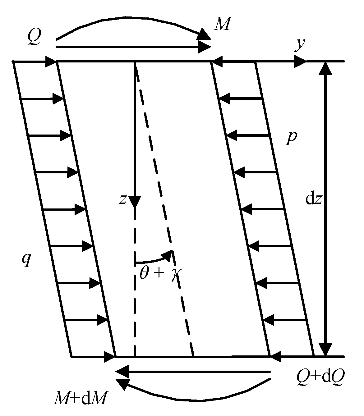
To analyze any microunit dz shown in Figure 2, the subscripts i and j were omitted for easy display. According to the balance of the lateral force bending moment, the second-order differential term can also be omitted [22]:
d Q d z = q p
d M d z = Q
where p is the lateral soil resistance in the front of the pile section, determined via p = ky, and k is the foundation reaction coefficient. q is the lateral soil resistance behind the pile section; Q and M are the shear force and bending moment at the top of the pile, respectively. All physical quantities in this text are positive in the direction shown in Figure 2.

2.2. The Relationship between Internal Force and Deformation of the Pile Body

To consider the influence of pile-body shear deformation on the force deformation analysis of large-diameter piles, Timoshenko beam theory was introduced. The pile-body displacement and internal forces meet the following relationships [6]:
θ = d y d z γ
M = E I d θ d z = E I d 2 y d z 2 d γ d z
Q = K p G p A p γ = K p G p A p d y d z θ
where θ is the bending moment angle generated by the bending moment action of the cross section of the pile body, γ is the shear angle generated by the shear force of the pile body; Kp is the Timoshenko shear coefficient, depending on the cross-sectional shape of the pile, for the hollow round-pipe section: Kp = 2 (1 + νp)/(4 + 3νp) [23], with νp being the Poisson’s ratio of the pile; Gp is the shear modulus of the pile body; and Ap is the cross-sectional area of the pile body.

2.3. Solving the Coefficient of the Free-Segment Transfer Matrix on the Mud Surface

In this paper, the subscripts (i, j) are omitted except for the state quantity S(i, j). The free section above the mud surface has no soil layer and does not provide soil resistance, that is, in Equation (1) p = 0, we obtain
d Q d z = q
By deriving Equation (5) and combining it with Equation (6), we obtain
d γ d z = q K p G p A p
Substituting Equation (7) into Equation (4), we calculate the following:
d 2 M d z 2 = E I d 4 y d z 4
From the above formulas combined with Equations (2)–(4), the f transfer matrix equation for the free-section pile-body response on the mud surface is obtained:
d y d z = θ + Q K p G p A p d θ d z = M E I d M d z = Q d Q d z = q
Since the value Q changes in the first and third terms simultaneously, this paper proposes a variable constantization treatment method. The first variable is constantized as Q/KpGpAp in the first row of Equation (9). When solving using the transfer matrix method, Q/KpGpAp is regarded as the constant Qpreave/KpGpAp, which represents the average shear angle per unit length of the pile body. The improved formula for the free-segment pile-body response is as follows:
d y d z = θ + Q preave K p G p A p d θ d z = M E I d M d z = Q d Q d z = q
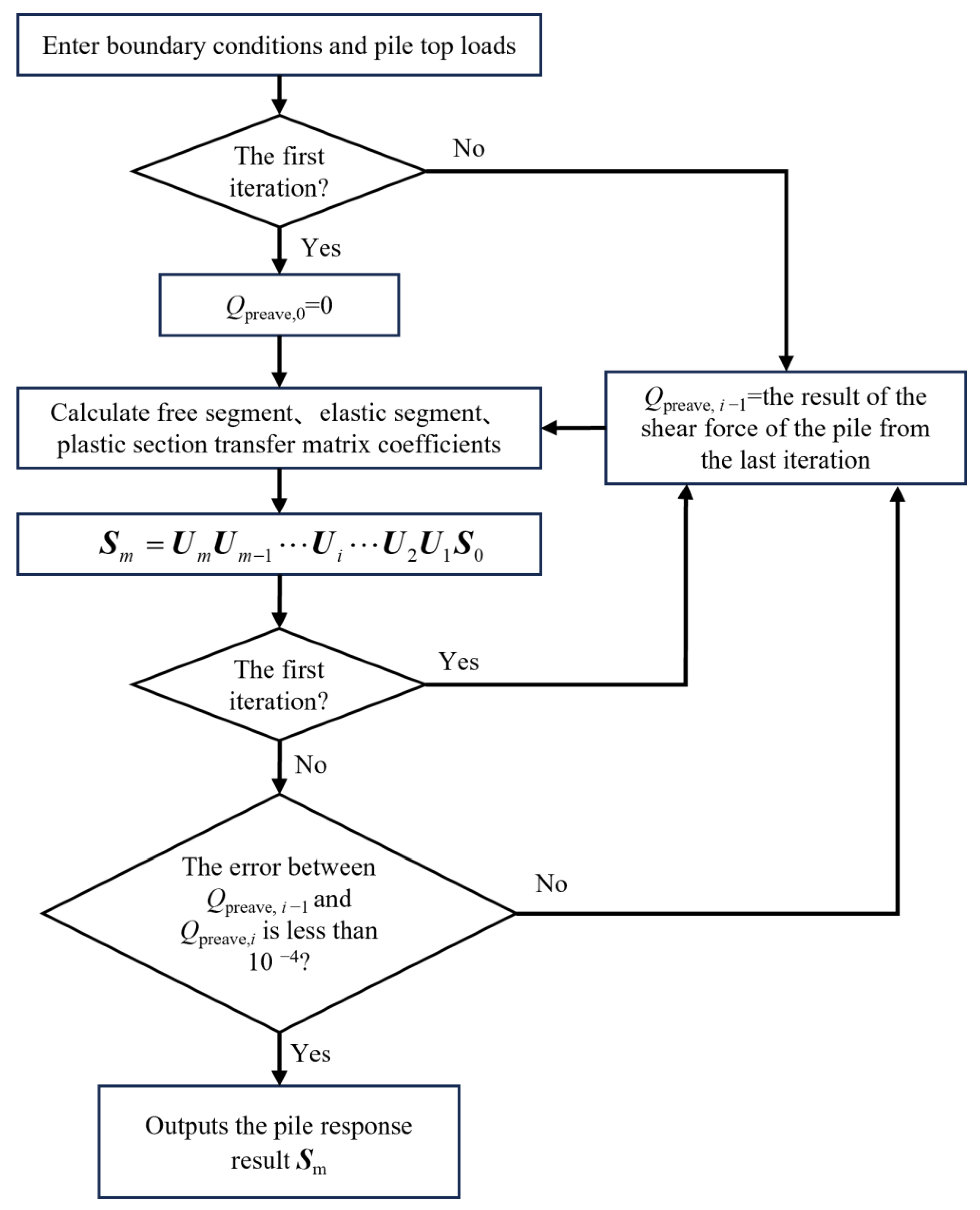
When calculating specifically, setting Qpreave = 0 yields the Q value for the pile-body response after the first step of calculation. The calculated Q value is solved as the constant term Qpreave and substituted into Equation (10). This process is repeated iteratively until the error between two consecutive iterations is less than a set value, thus obtaining a solution for the large-diameter, lateral-load-bearing pile’s response considering shear deformation of the pile body.
We can write Equation (10) as a matrix:
d S i , j d z = A S i , j + f
where S(i,j), A, and f are matrix variables, with S(i,j) being the quantity of the jth-element pile end in the ith-segment pile in the free segment. These matrix variables are as follows:
S i , j = y i , j θ i , j M i , j Q i , j T
f = Q preave K p G p A p 0 0 q T
A = 0 1 0 0 0 0 1 / E I 0 0 0 0 1 0 0 0 0
Using Laplace forward and reverse transformations to process Equations (11) and (13), we can obtain the following, in order:
L S z = F s
L f z = g s
Performing the Laplace transform on Equation (11) yields
F s = I × s A 1 S i , j 1 + I × s A 1 g s
Performing the inverse Laplace transformation on Equation (17) yields the following:
S i , j = L 1 I × s A 1 S i , j 1 + L 1 I × s A 1 g s
where I is a 4th-order identity matrix; the symbol “L−1” represents the inverse Laplace transformation; s represents the variable of the Laplace equation; S(i,j−1) is the jth-unit pile-top state in the ith-section pile in the free section; and g(s) and S(i,j−1) are expressed as follows:
g s = Q preave K p G p A p s 0 0 q s T
S i , j 1 = y i , j 1 θ i , j 1 M i , j 1 Q i , j 1 T
Then, the free-segment pass matrix is found as shown below (this derivation process is shown in Appendix B):
S i , j = U f S i , j 1
where the free-section pile-body transfer matrix coefficient Uf is as follows:
U f = 1 h j h j 2 2 E I j h j 3 6 E I j γ 1 0 1 h j E I j h j 2 2 E I j γ 2 0 0 1 h j γ 3 0 0 0 1 γ 4 0 0 0 0 1
In Equation (22),
γ 1 = Q preave h j K p G p A p + q h j 4 24 E I j γ 2 = q h j 3 6 E I j γ 3 = q h j 2 2 γ 4 = q h j

2.4. Solution of the Transfer Matrix Coefficient of the Elastic Segment under the Mud Surface

In the elastic section, the soil on the pile side is in an elastic state, and the soil resistance is determined via p = ky. Deriving Equation (5) and combining Equation (1) yields
d γ d z = q k y K p G p A p
Substituting Equation (24) into Equation (4) and finding the secondary derivation yields
d 2 M d z 2 = E I d 4 y d z 4 + k K p G p A p d 2 y d z 2
By finding a primary derivative of Equation (2) by combining it with Equation (1), we obtain
d 2 M d z 2 = q k y
Similarly, introducing the variable constantization operation yields an improved elastic-segment pile-response matrix equation:
d y d z = θ + Q preave K p G p A p d θ d z = M E I d M d z = Q d Q d z = k y + q
Writing Equation (27) as a matrix, we calculate
d S i , j d z = A S i , j + f
The matrix variables S(i,j) are the same as those defined in Equation (12), and the variables f and A are defined as follows:
f = Q preave K p G p A p 0 0 q T
A = 0 1 0 0 0 0 1 / E I 0 0 0 0 1 k 0 0 0
If we let β4 = k/4EI, according to the derivation method of Zhu et al. [21], for the free segment, the elastic-segment transfer matrix expression can be obtained as follows (this derivation process is shown in Appendix B):
S i , j = U e S i , j 1
Within this, the free-section pile-body transfer matrix coefficient Ue is defined as follows:
U e = φ 1 φ 2 2 β 2 β 2 φ 3 k β φ 4 k χ 1 β φ 4 φ 1 2 β 3 φ 2 k 2 β 2 φ 3 k χ 2 k φ 3 2 β 2 k φ 4 4 β 3 φ 1 φ 2 2 β χ 3 k φ 2 2 β k φ 3 2 β 2 β φ 4 φ 1 χ 4 0 0 0 0 1
In Equation (32),
χ 1 = Q preave φ 2 2 K p G p A p β + q 1 φ 1 k χ 2 = Q preave 1 φ 1 K p G p A p + q β φ 4 k χ 3 = k Q preave φ 4 4 K p G p A p β 3 + q φ 3 2 β 2 χ 4 = k Q preave φ 3 2 K p G p A p β 2 + q φ 2 2 β
In Equations (32) and (33), φ1, φ2, φ3, and φ4 are defined as follows:
φ 1 = cos β h j cosh β h j φ 2 = cos β h j sinh β h j + sin β h j cosh β h j φ 3 = sin β h j sinh β h j φ 4 = cos β h j sinh β h j sin β h j cosh β h j

2.5. Solution of the Transfer Matrix Coefficient of the Plastic Segment under the Mud Surface

When the soil in the plastic zone reaches the yield displacement, and the soil resistance p reaches its limit value pu, which is similar to that of the free section, we can obtain the response of the pile body in the plastic zone under the mud surface by using the transfer matrix equation:
d y d z = θ + Q preave K p G p A p d θ d z = M E I d M d z = Q d Q d z = p u + q
Comparing Equations (35) and (10), we find that the difference between the plastic segment and the free segment is only in the fourth row, and since pu is a constant value, it is enough to replace q in Equation (10) with (−pu + q) and thus obtain the desired result.
The plastic-segment transfer matrix coefficient Uu is as follows (this derivation process is shown in Appendix C):
U u = 1 h j h j 2 2 E I j h j 3 6 E I j η 1 0 1 h j E I j h j 2 2 E I j η 2 0 0 1 h j η 3 0 0 0 1 η 4 0 0 0 0 1
In the above formula,
η 1 = Q preave h j K p G p A p + q p u h j 4 24 E I j η 2 = q p u h j 3 6 E I j η 3 = q p u h j 2 2 η 4 = q p u h j
Then, we obtain the plastic-segment transfer matrix expression as
S i , j = U u S i , j 1
Combining Equations (21), (31), and (38), we obtain the matrix transfer equation for any point m of the pile body:
S m = U m U m 1 U i U 2 U 1 S 0
In this formula, S0 represents the pile-top state quantity; when point i(i = 1, 2, …, m) is located in the free segment, Ui takes Uf for calculation; when i is located in the plastic section, Ui takes Uu for calculation; and when point i is located in the elastic segment, Ui takes Ue for calculation. When m = n, the above equation represents the response of the complete pile structure.

2.6. Boundary Conditions and Calculation Process

2.6.1. Boundary Conditions

Equation (39) is a matrix equation with eight variables: pile-top displacement, rotation angle, bending moment, and shear force (the S0 variable); and pile-end displacement, rotation angle, bending moment, and shear force (the Sn variable). To solve Equation (39), the following four boundary conditions must be introduced:
(1)
Pile-top free constraint: M0 = Mt, Q0 = Fh;
(2)
Pile-top fixed constraint: θ0 = 0, Q0 = Fh;
(3)
Free constraint at the pile end: Mn = 0, Qn = 0;
(4)
Pile-end fixed constraint: yn = 0, θn = 0.

2.6.2. Calculation Process

Substituting the known boundary conditions into Equation (39), the remaining four unknown parameters can be solved. The specific solution process is as follows:
(1)
For the initial calculation, Qpreave = 0 is set, and assuming that the mud surface below is in the elastic stage, the initial calculation result is obtained according to the pile-bearing response transfer matrix.
(2)
After the first step of calculation, the pile-body shear force value can be obtained. The pile-body shear force is taken as a constant term Qpreave, and then substituted into the previous process for iterative calculation. At the same time, according to the calculation results of the first step, the method to judge whether the points under the mud surface are in the elastic stage or the plastic stage is as follows: if they are in the elastic stage, the elastic-segment transfer matrix formula continues to be used in the second step of iterative calculation; if they are in the plastic stage, the corresponding unit is calculated by using the plastic-segment transfer matrix formula when the second step is iteratively calculated, and the calculation result of the second step is obtained.
(3)
After repeating the above steps until the Qpreave calculated in the last two steps meets the convergence error (10−4 in this paper), the iterative calculation is over, at which time the result is the final result.
Figure 3 shows the specific calculation flow chart of this program.

3. Case Comparison

3.1. Case 1

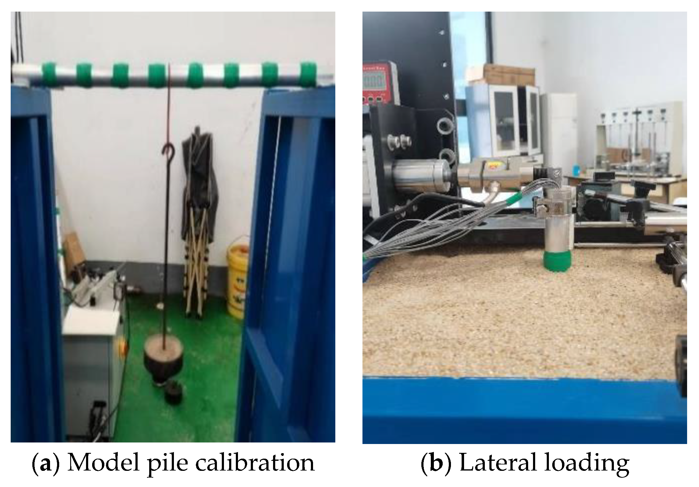
A series of model tests were conducted on the bearing characteristics of pile foundation under lateral loads, as shown in Figure 4. Two model piles were used. The length of one pile was 0.6 m and the length of the other was 0.7 m. The remaining pile–soil parameters were as follows: the length of the pile on the mud surface was La = 0.08 m, the pile diameter D was 0.03 m, the wall thickness t was 0.001 m, the bending stiffness EI was 0.684 kN·m2, and the Poisson’s ratio vp was 0.3; the foundation soil was uniformly paved Fujian standard sand, and the pile top and pile end were in a free state. The lateral load at the pile top was Fh60 = 0.0628 kN or Fh70 = 0.0849 kN, respectively. All of these listed parameters are displayed in Table 1. Based on the displacement data measured at the soil surface [24] during the model testing of the pile with a diameter of 0.6 m, the parameters m = 3.2 × 10⁴ kN/m4, z0 = 0.15 m, and n = 0.75, which form the three-parameter model of the experimental soil, were obtained.
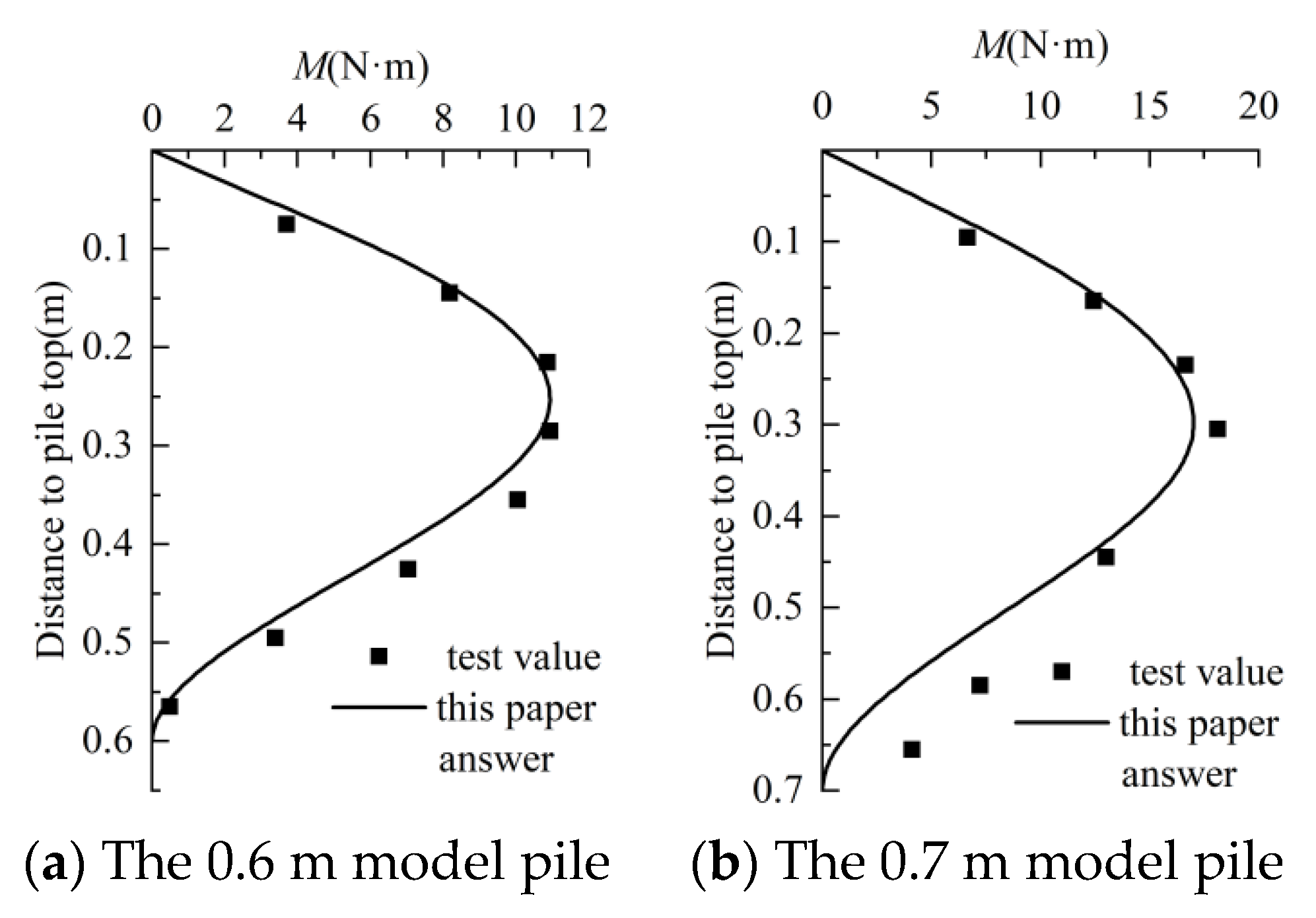
The method in Section 2 was used to calculate the test parameters of the pile with the length of 0.7 m. From the calculation results in Figure 5, it can be seen that the calculated bending moment (M) is in good agreement with the test results. Therefore, it can be concluded that the method in this paper is correct and reasonable.
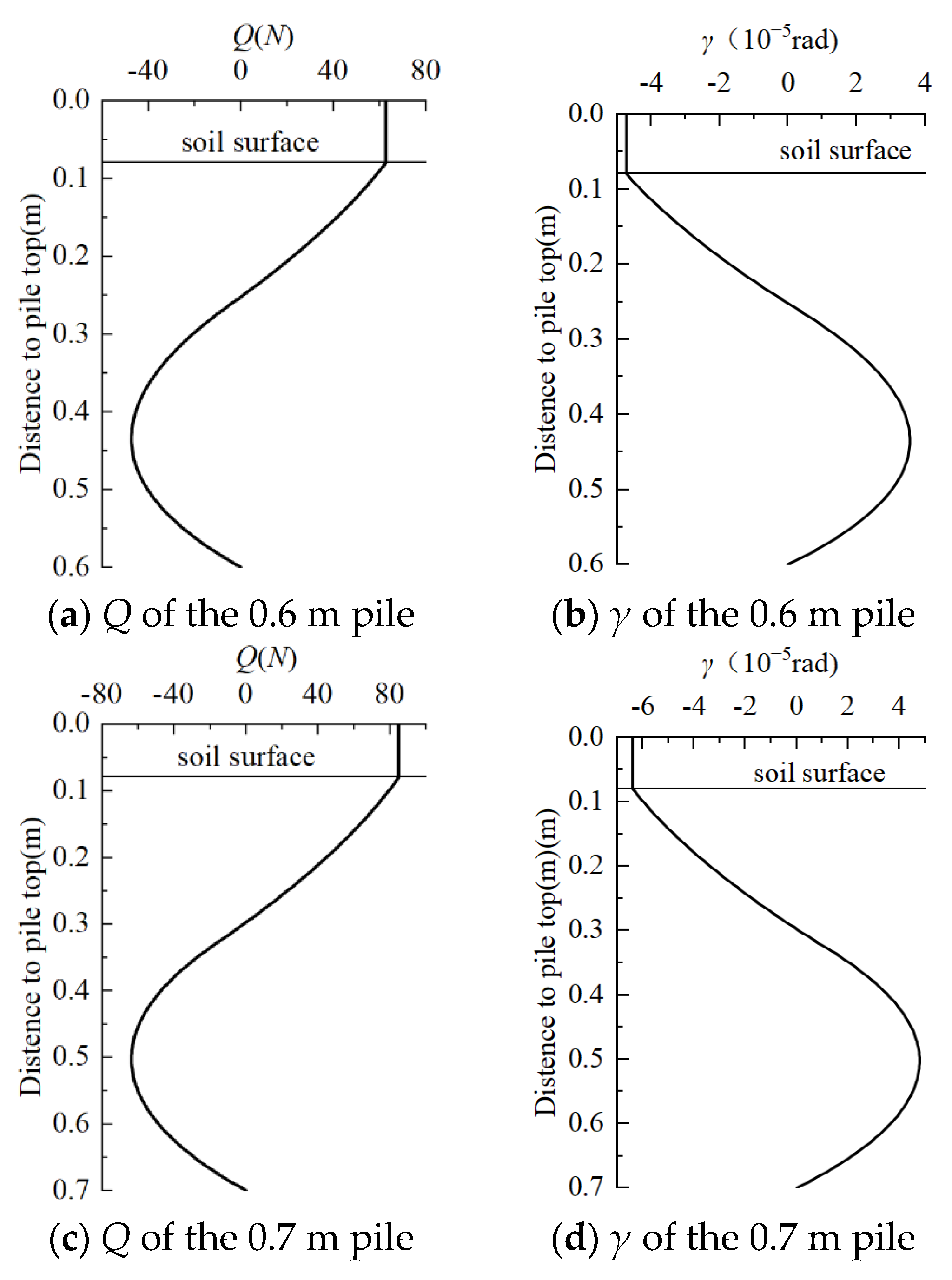
In this method, the influence of the shear angle (γ) of the pile body on the response of the pile is considered. The shear force and shear angle of each model pile body were thus calculated, as shown in Figure 6. It can be seen that the changing trend of the shear angle of each pile body is consistent with that of its shear force. The shear force above the mud surface remains unchanged, as does the shear angle above it. In the part below the mud surface, affected by soil resistance, the shear angle decreases and then increases with the shear force before finally returning to near zero.
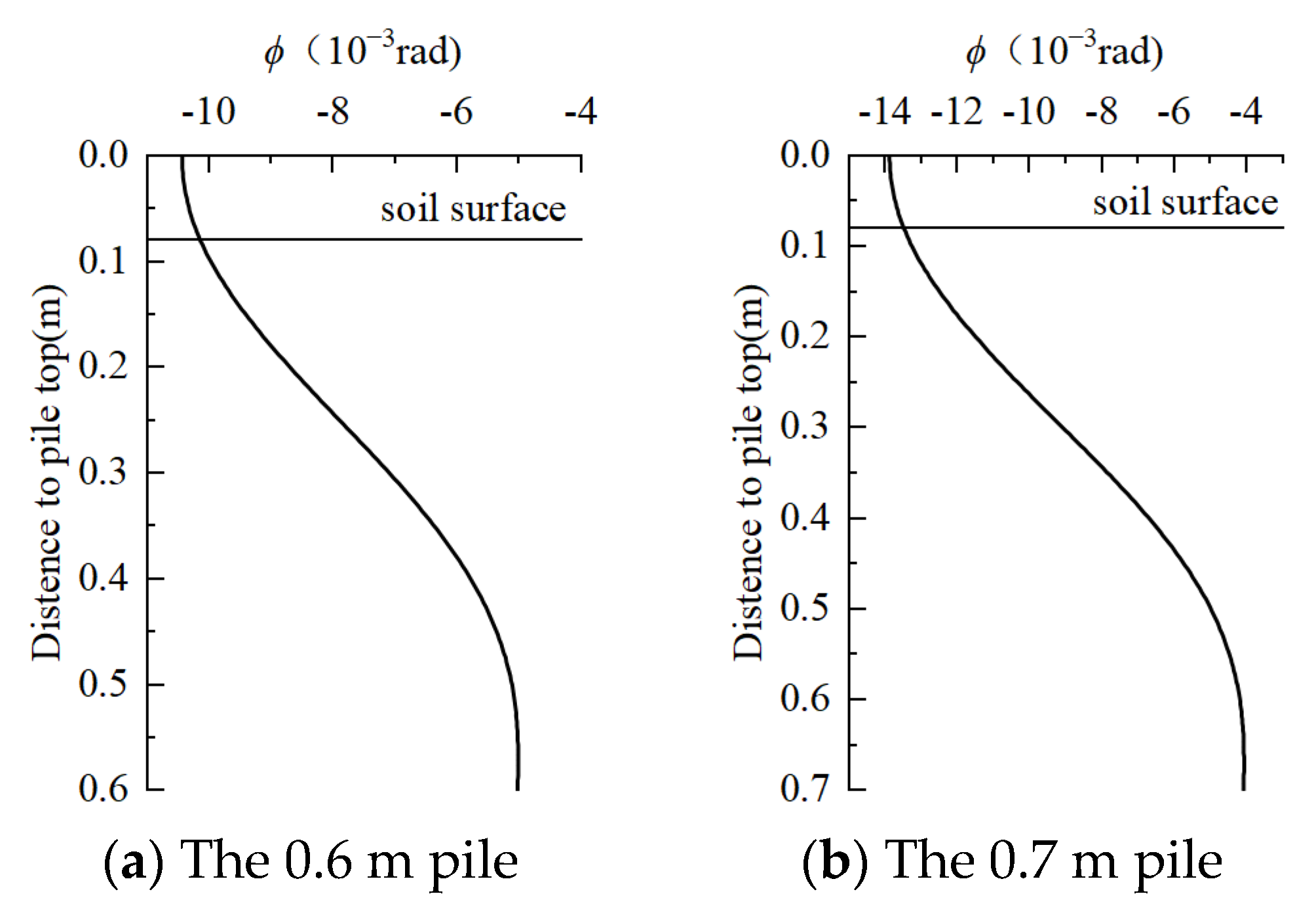
Figure 7 shows the total rotation (ϕ) of the pile-body sections. It can be seen that the neutral shaft angle gradually decreases along the depth, with a slower reduction speed on the mud surface. After entering the mud surface, the neutral shaft angle first decreases rapidly and then changes flatly when approaching the pile end. Comparing Figure 6 and Figure 7, it can be seen that in the corner deformation of each test model pile, the cross-sectional shear angle accounts for a relatively small proportion. For both the first and second model piles with lengths of 0.6 m and 0.7 m, respectively, the shear angle of the section at the top of the pile only accounts for 0.46% of the total rotation. Because of their small diameters, shear deformation has little effect on their overall deformation [13].

3.2. Case 2

The results of the centrifugal model test carried out by Zhu et al. [25] were comparatively analyzed to further verify the applicability of the proposed method. The parameters of the prototype pile and soil were as follows: the pile length L was 56.75 m, within which La = 6.75 m on the mud surface and Lb = 50 m below the mud surface; the pile diameter D was 2.5 m; the wall thickness t was 0.045 m; the bending stiffness EI was 56.66 GN·m2; the Poisson’s ratio vp was 0.33. The foundation soil was Fujian standard sand, the pile top and pile end were in a free state, and a lateral load Fh was applied on the pile top. Zhu et al. [25] reversed the displacement data at the mud surface under a lateral load Fh = 4827 kN in their set of tests, and obtained the parameters m = 4000 kN/m4, z0 = 0.1 m, and n = 0.3 for the three-parameter model of the soil mass. The results of the other three sets of experiments conducted by Zhu et al. [25] were compared and analyzed using these obtained parameters.
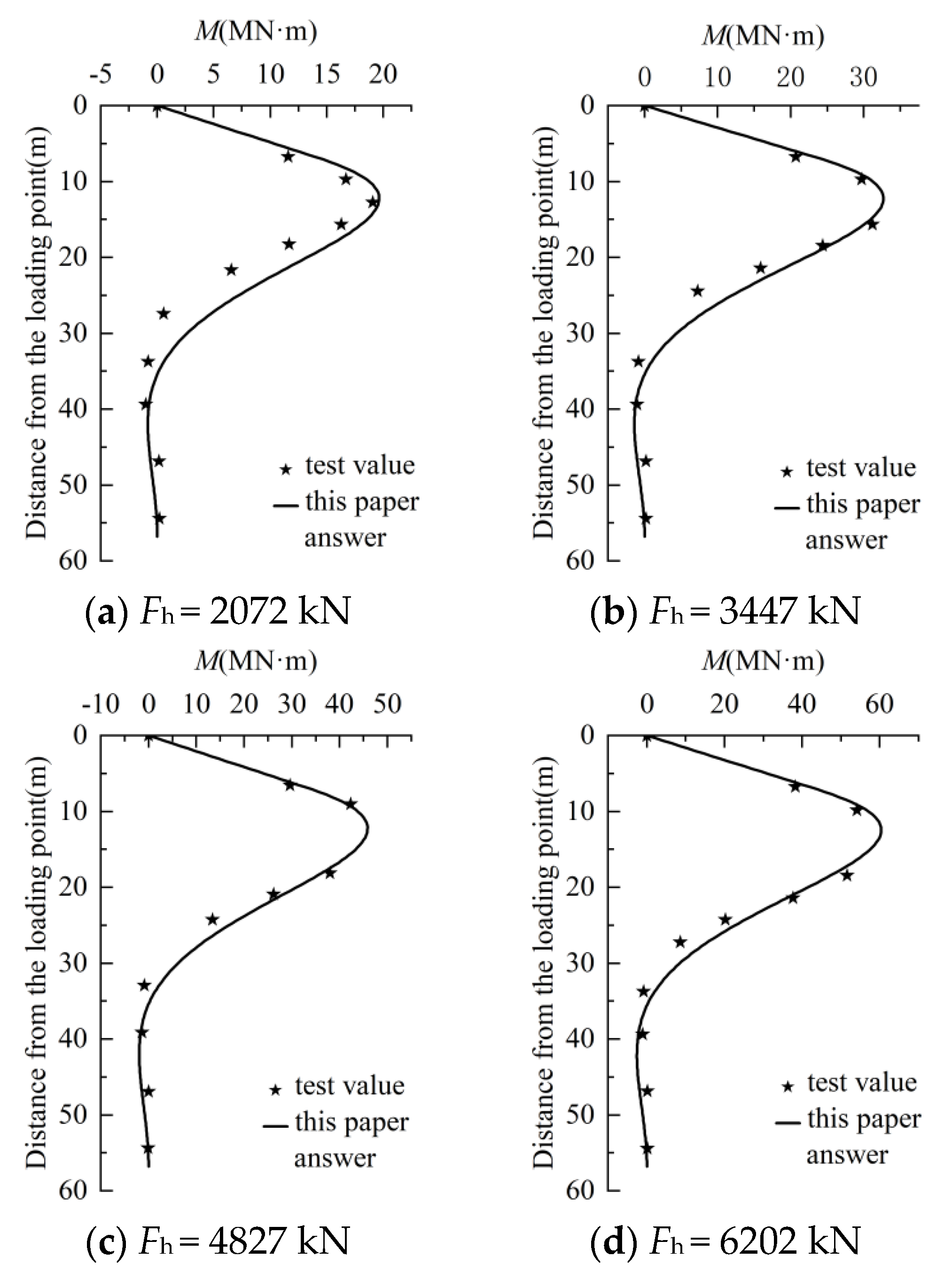
The comparison results of the theoretical solution in this paper and measured data are shown in Figure 8. It can be seen that the bending moments calculated using the method in this paper are in good agreement with the test results of Zhu et al. [25], so the calculation method and the program proposed in this paper are correct and reasonable.
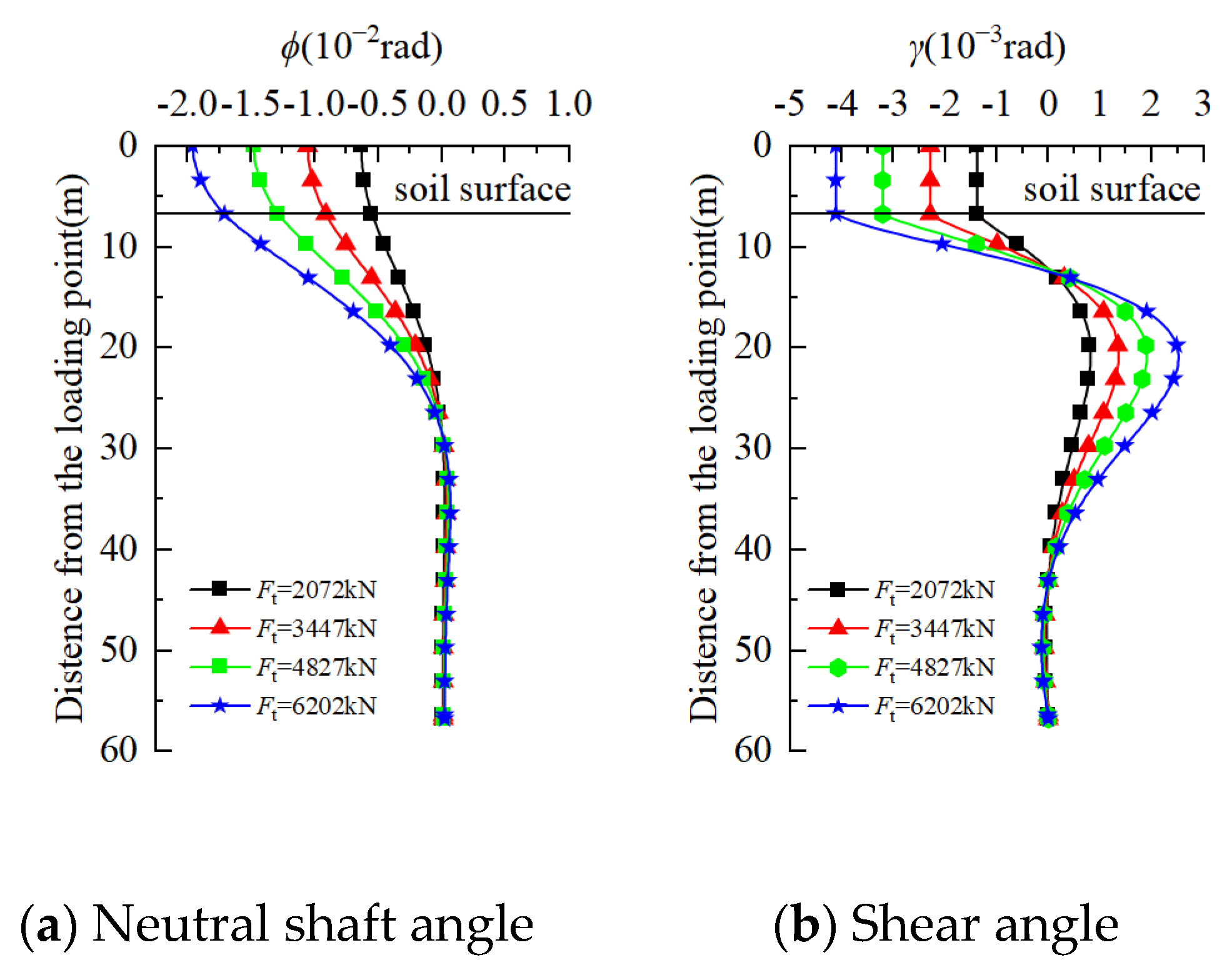
The shear deformation of the pile body in the large-diameter lateral-load pile tests by Zhu et al. [25] was analyzed. The calculation results for the total rotation (ϕ) and shear angle (γ) of the pile body under each group of tests are shown in Figure 9.
It can be seen from Figure 9 that the total rotation and shear angle of the pile body under different lateral loads of the same pile are consistent. Specifically, above the mud surface and in shallow soil, the neutral shaft angle gradually decreases with increasing depth. After reaching a depth of 20 m below the mud surface, the neutral shaft angle tends to shift towards 0, and remains almost unchanged with increasing depth. The shear angle change law of the pile body is consistent with that of the test model pile in this paper: above the mud surface, the shear angle does not change, and below it, the shear angle decreases and then increases with increasing depth, finally returning to near zero.
Comparing the total rotation and shear angle data, it is found that in the Zhu et al. [25] tests, when the lateral loads are Fh = 207 2kN, 3447 kN, and 4827 kN at the pile top, the shear angle at the top of the pile accounts for 2.17% of the central axis-rotation angle, which is much larger than the 0.46% observed in our test model pile. This verifies to a certain extent that with the gradual increase in the diameter of the pile foundation, the influence of cross-sectional shear deformation on the response of the pile body cannot be ignored [13]. When the lateral load increases to Fh = 6202 kN, the shear angle at the top of the pile accounts for 2.1% of the central axis-rotation angle, which is slightly reduced compared with the other three groups. This means that when the lateral load of the model pile increases to a certain extent, the influence of shear deformation of the pile body on its overall deformation will be reduced. This phenomenon is analyzed in detail later in this paper.

4. Comparative Analysis of the Timoshenko Beam and Euler–Bernoulli Beam

In the analysis of force deformation of large-diameter laterally loaded piles, the shear deformation of the pile body is an important influencing factor. The deformation of the large-diameter laterally loaded pile body based on the beam theories of Timoshenko beam and Euler–Bernoulli is analyzed by using the calculation method presented in this paper; the deformation of the large-diameter laterally loaded pile body under different levels of pile–soil relative stiffness and different lateral loads is also analyzed. The pile–soil relative stiffness coefficient is calculated using the following formula [26]:
T = E p I p E s L p 4 4
where Es is the modulus of elasticity of the soil; Lp is the depth of the pile penetration; and EpIp is the bending stiffness of the pile body. When T > 0.7, it indicates that the pile is a rigid pile; when T < 0.2, it is a flexible pile; and when T is in between these values, it is a semi-rigid pile. Assuming that the pile body is below the mud surface, with an elastic modulus Ep of 200 GPa, a Poisson’s ratio vp of 0.3, and a wall thickness t of 0.2 m, the pile diameter D value ranges from 1 m to 12 m; the specific pile length, pile diameter, and pile soil relative stiffness coefficients are shown in Table 2. The foundation was calculated using the three-parameter model with parameters m = 6 × 10³ kN/m4, z0 = 0.1 m, and n = 0.3, and the elastic modulus of the foundation soil is Es = 40 MPa. The boundary conditions of the pile top and pile end are free, and only the lateral load Fh acts on the pile top.

4.1. Comparison of Load–Displacement Curves of Timoshenko Beams and Euler–Bernoulli Beams

Based on the pile-top load–displacement data of the Timoshenko beam and Euler–Bernoulli beam, the load–displacement data are normalized: the ratio of the lateral displacement of the pile top of each pile to the lateral displacement of the pile top under the lateral ultimate load of each pile is taken as the abscissa, and the ratio of the lateral load Fh of each pile to the lateral ultimate bearing capacity of the pile Fuh is used as the ordinate. The normalized load–displacement curves of each pile are shown in Figure 10. It is basically observed from Figure 10 that the differences between the normalized load–displacement curves of the Timoshenko beam and Euler–Bernoulli beam are negligible under different pile–soil relative stiffness levels and different diameters. The two curves almost overlap, indicating that considering the shear deformation effects of large-diameter piles has limited influence on the lateral capacity, which is consistent with the results from Byrne et al. [5,27] and Gupta et al. [13,28,29].
Based on the pile-top load–displacement data of the Timoshenko beam and Euler–Bernoulli beam, the normalized load–displacement curves of each pile are plotted in Figure 10. For flexible piles (T = 0.15), the curves intersect around Fh/Fuh = 0.6 during the development process. When Fh/Fuh < 0.6, at the same value of y/yu, the value of Fh/Fuh is smaller t for smaller pile diameters, and when 0.6 < Fh/Fuh < 1, at the same value of y/yu, the value of Fh/Fuh is greater for smaller pile diameters. Finally, when Fh/Fuh = 1, all normalized load–displacement curves intersect at one point. For semi-rigid piles (T = 0.45), the normalized load–displacement curves of piles with different diameters coincide when Fh/Fuh < 0.6, and when 0.6 < Fh/Fuh < 1, at the same value of y/yu, the value of Fh/Fuh is greater for smaller pile diameters. When Fh/Fuh = 1, all normalized load–displacement curves intersect at one point. For rigid piles (T = 0.75), piles of different diameters only intersect at a point when Fh/Fuh equals 0 and 1, and when 0 < Fh/Fuh < 1, the normalized load–displacement curve is more to the left for smaller pile diameters. This shows that in the initial loading stage (Fh/Fuh < 0.6), the lateral displacement development of flexible piles becomes faster with the increasing pile diameter, that is, the displacement ratio y/yu increases less with the increasing pile diameter for a given ratio of lateral load to lateral ultimate bearing capacity (Fh/Fuh) With an increase in the pile–soil relative stiffness, this phenomenon gradually changes, and the lateral displacement development of rigid piles slows down with the increasing pile diameter, that is, y/yu increases more with the increasing pile diameter for a given ratio of lateral load to lateral ultimate bearing capacity (Fh/Fuh).
At the same time, in Figure 10, when T = 0.15 and Fh/Fuh < 0.25, the load–displacement curve shows a linear relationship (elastic section). When Fh/Fuh > 0.25, it gradually enters the nonlinear section (elastoplastic section). As the pile–soil relative stiffness increases, the load–displacement relationship changes from elasticity to elastoplasticity corresponding to the Fh/Fuh value. When T = 0.45, the Fh/Fuh value is 0.5, and when T = 0.75, it increases to 0.6. The difference between the internal force and deformation of the pile body for rigid and flexible piles causes this phenomenon: for flexible piles, because the depth of the pile body into the soil is large enough, it can be regarded as a semi-infinite long beam and its deformation is mainly deflection and deformation of the pile body; for rigid piles, under the action of lateral force, the pile body will gather around a certain center, similar to the phenomenon of rigid body rotation. When the load increases to a certain extent, the pile-body rotation intensifies and lateral displacement also increases rapidly until it enters the limit state [26].

4.2. Deformation Analysis of Timoshenko Beams and Euler–Bernoulli Beams

Under a non-limiting load, with the increase in pile diameter, the influence of shear deformation of the pile body is greater, and the overall deformation of the pile body is more influenced by the shear deformation of the pile body in flexible piles and semi-rigid piles than it is in rigid piles. However, when the load is close to the loading stage, the pile deformation data calculated based on the Timoshenko beam and Euler–Bernoulli beam theories tend to be consistent, and the influence of pile shear deformation can be ignored.
Figure 11 compares the lateral displacement at the pile top according to the Timoshenko beam with that according to the Euler–Bernoulli beam across different diameters and relative stiffness levels. The abscissa standard is the ratio of the lateral load Fh borne by each pile to the lateral ultimate bearing capacity Fuh. The ordinate is the ratio of pile-top lateral displacement yT calculated based on the Timoshenko beam to that yE calculated based on the Euler–Bernoulli beam for each pile. Figure 11a shows that for flexible piles, the maximum ratio of yT to yE is only 1.006 when D = 1 m. As the pile diameter increases, this ratio gradually increases. When D = 12 m, this ratio reaches a maximum value of 1.094. It can be seen from Figure 11b that for semi-rigid piles, the maximum ratio of yT to yE is only 1.002 when D = 1 m. As the pile diameter increases, this ratio gradually increases. When D = 12 m, this ratio reaches a maximum value of 1.092. It can be seen from Figure 11c that for rigid piles, the maximum ratio of yT to yE is only 1.001 when D = 1 m. As the pile diameter increases, the ratio of yT to yE gradually increases, and when the pile diameter increases to D = 12 m, this ratio is 1.042. This indicates that under a non-limiting load, with an increase in the pile–soil relative stiffness, the lateral displacement ratio of piles with the same diameter based on the Timoshenko beam and Euler–Bernoulli beam gradually decreases. At the same time, when the pile–soil relative stiffness is constant under a non-limiting load, the lateral displacement ratio based on the Timoshenko beam and Euler–Bernoulli beam increases with the increasing lateral pile diameter of the loaded pile. This indicates that shear deformation of the pile body has an increasing influence on the response of the pile body as the lateral pile diameter increases, which becomes more and more significant.
As can be seen from Figure 11, the ratio of the lateral displacement of the pile top calculated for the same pile based on the Timoshenko beam and the Euler–Bernoulli beam is related to the loading level: as the lateral load increases, the ratio does not change at the initial stage; with the continuous increase in lateral load, the ratio also increases to a certain extent, and after reaching the peak, with the further increase in lateral load, the ratio of lateral displacement of the pile top decreases to a certain extent. After the lateral load reaches 0.9 times the lateral ultimate load of the pile, the ratio of the lateral displacement of the pile top calculated based on the Timoshenko beam and the Euler–Bernoulli beam decreases rapidly, and the ratio tends to shift towards 1 when the lateral load becomes closer to the lateral ultimate bearing capacity. At the same time, with an increase in the pile–soil relative stiffness, there is no change in the lateral displacement ratio of the pile top based on the Timoshenko beam and Euler–Bernoulli beam from the initial stage. The corresponding Fh/Fuh value also increases when it starts to increase, and the amplitude of this increase first increases and then decreases. For piles with D = 12 m and T = 0.15, the lateral displacement ratio of the pile top begins to increase after the abscissa Fh/Fuh value reaches 0.1; when Fh/Fuh = 0.2, the ratio of yT to yE increases from 1.06 in the initial stage to 1.094, with an increase of 0.034; as the pile–soil relative stiffness coefficient increases to T = 0.45, the lateral displacement ratio of the pile top only begins to change after the abscissa Fh/Fuh value reaches 0.4; the ratio reaches a peak when Fh/Fuh = 0.75, and the ratio of yT to yE also increases from 1.056 to 1.092, with an increase of 0.036. When T = 0.75, the lateral displacement ratio of the pile top begins to change after the abscissa Fh/Fuh value reaches 0.5. The ratio reaches a peak when Fh/Fuh = 0.8, and the ratio of yT to yE increases from 1.027 to 1.043, with an increase of only 0.016. This shows that the top displacement gap of rigid piles based on Timoshenko beam and Euler–Bernoulli beam calculations is small, and the change in displacement ratio is more stable. However, the top displacement gap in flexible piles and semi-rigid piles based on Timoshenko beams and Euler–Bernoulli beams is larger than that in rigid piles, and the displacement ratio changes more sharply. This phenomenon occurs because with the increase in the pile–soil relative stiffness, the displacement mode of the pile foundation changes from bending deformation of the pile to overall rotation, and the shear deformation of the pile body has less influence on the overall displacement of the pile foundation.
Figure 12 shows the results of comparing the total rotations of pile tops under the two theories of Timoshenko beam and Euler–Bernoulli beam under three different pile–soil relative stiffness levels: the abscissa is the same as that in Figure 11, and the ordinate is the ratio of the pile-top total rotation calculated based on Timoshenko beam theory (ϕT) to that calculated based on Euler–Bernoulli beam theory (ϕE). Under the same pile–soil relative stiffness, as the pile diameter increases and Fh/Fuh < 1, the ratio of ϕT to ϕE gradually increases. For piles with D = 1 m, if T is 0.15, 0.45, and 0.75, the ratio of ϕT to ϕE is 1.013, 1.005, and 1.002, respectively. When the pile diameter increases to 12 m, this ratio increases to 1.197, 1.198, and 1.112, respectively, further verifying that shear deformation of the pile body has an increasing influence on the response of laterally loaded piles as the lateral pile diameter increases.
It can also be seen from Figure 12 that the ratio of total rotations of the pile top based on the Timoshenko beam to that based on the Euler–Bernoulli beam does not change at the initial stage of loading; the ratio increases to a certain extent as the lateral load continues to increase; and after reaching the peak, the ratio gradually decreases with the further increase in the lateral load. When the lateral load shifts towards the lateral ultimate bearing capacity, the ratio quickly shifts to 1. Similarly, with the increase in pile diameter, the ratio of total rotations of the pile top based on the Timoshenko beam to that based on the Euler–Bernoulli beam remains unchanged at the initial stage. The corresponding Fh/Fuh value also increases when it begins to increase, and the amplitude of its increase first rises and then falls. For piles with D = 12 m and T = 0.15, after the abscissa Fh/Fuh value reaches 0.1, the ratio of the total rotations of the pile top begins to increase with the increasing lateral load. This ratio reaches a peak when Fh/Fuh = 0.15: at this point, the ratio of ϕT to ϕE increases from 1.187 to 1.196, which is an increase of 0.009. As the pile–soil relative stiffness coefficient increases to T = 0.45, the ratio of total rotations of the pile top begins to change after the abscissa Fh/Fuh value reaches 0.4, and this ratio reaches a peak when Fh/Fuh = 0.55, increasing from 1.187 to 1.198, which is an increase of 0.011. When T = 0.75, the pile only begins to change the ratio of the neutral axis angle at its top after the abscissa Fh/Fuh value reaches 0.5, and this ratio reaches a peak when Fh/Fuh = 0.65, increasing from 1.107 to 1.112, which is an increase of only 0.005. The difference between the neutral shaft angle of the pile top calculated based on the Timoshenko beam and that calculated based on the Euler–Bernoulli beam is small for rigid piles, and the change in the total rotations ratio is more stable. However, the difference between the total rotations of the pile top is larger than that of rigid piles for flexible piles and semi-rigid piles based on the Timoshenko beam and Euler–Bernoulli beam calculations, and the change in the total rotations ratio is more severe.

4.3. Analysis of the Relationship between the Shear Angle and Total Rotation of the Timoshenko Beam

Under a non-limiting load, the proportion of the shear angle in the neutral shaft angle obtained based on the Timoshenko beam is increased with the increase in pile-body diameter. However, when the load is close to the loading stage, the proportion of the shear angle in the neutral shaft angle tends to be 0, that is, the influence of the shear deformation of the pile body on the overall deformation of the pile body can be ignored.
The shear angle generated by piles using Timoshenko beam theory was calculated using the method described in this paper. The ratio of the shear rotation of the pile section to the total rotation was taken as the ordinate, while the abscissa was the same as that used in Figure 11 and Figure 12. Shear angles for each pile diameter were plotted against load change curves, as shown in Figure 13.
It can be observed from Figure 13 that when the pile–soil relative stiffness is constant, the cross-sectional shear deformation at the corners of the pile top increases with increasing pile diameter under non-limiting loading conditions. For piles with D = 1 m, when T = 0.15, 0.45, and 0.75, the highest ratio of pile-top shear angle to total rotations is only 0.012, 0.004, and 0.001, respectively. However, this ratio gradually increases with increasing pile diameter until it reaches a maximum value at D = 12 m. This ratio reaches as high as 0.152, 0.145, and 0.084, respectively. This verifies that under non-limiting load conditions, increasing the pile diameter results in a greater influence of shear deformation on the lateral response of piles affected by lateral loads.
At the initial loading stages under non-limiting loads, there is no change in proportion between the top shear angles at each pile’s neutral shaft angles. However, as each lateral load continues to increase towards the lateral ultimate load (LUL), this proportion rapidly shifts towards 0. This phenomenon can be attributed to γ = Q/KpGpAp, where γ represents shear angles on a pile’s body proportional to its Q value. KpGpAp only depends on parameters specific to each individual pile and remains constant. During initial loading stages when piles are within the elastic range, their load–displacements show linear trends, resulting in linear changes for both their neutral axis-rotation angles and shear angles. This keeps their ratio unchanged. As the lateral loads increase further into plastic stages, where the piles’ displacements increase rapidly while their Q values change slowly, the proportion between the top shear angle of each pile and the pile’s total rotation decreases. When the lateral loads approach LULs, where theoretical displacement for the pile bodies tends towards infinity while their Q values remain limited, the proportion between each pile’s top shear angle and total rotation moves towards 0. This indicates that angular displacement for laterally loaded pile bodies during the limit state is almost entirely provided by bending angles, with the extra shear angles from the Timoshenko beam theory having a negligible impact on the deformation of the pile body compared to those from the Euler–Bernoulli beam theory.
For piles with the same diameter, the value of Fh/Fuh, corresponding to the beginning of the decrease in the ratio of pile-top shear angle to total rotation, increases with the pile–soil relative stiffness. For piles with D = 12 m, when T = 0.15 and Fh/Fuh reaches 0.1, the ratio of pile-top shear angle to total rotation begins to decrease; similarly, when T = 0.45 and Fh/Fuh reaches 0.4, or when T = 0.75 and Fh/Fuh reaches 0.5, the ratio of pile-top shear angle to total rotation also begins to decrease. Figure 9 shows that piles with greater relative stiffness enter the plastic section slower as the lateral load increases. This causes the Fh/Fuh value, corresponding to the ratio between the pile-top shear angle and the pile’s total rotation, to decrease as the T value for piles with the same diameter increases.

5. Conclusions

This paper studied the effect of pile shear deformation on the deformation of large-diameter laterally loaded piles under different loading levels, and the following conclusions are drawn:
(1)
Firstly, based on the Timoshenko beam theory, the transfer matrix coefficient and pile-body response equation derived from the idea of variable constantization, which greatly reduces the difficulty of programming and calculation, was introduced in this paper. Then, several sets of case studies were used to verify the correctness of the method and programming process used in this paper.
(2)
It is observed that the load–displacement curves of laterally loaded piles based on Timoshenko beam theory and Euler–Bernoulli beam theory basically overlap, which means that considering the effect of shear deformation has limited influence on the lateral capacity of large-diameter piles.
(3)
Under a non-limiting load, with the increase in pile diameter, the influence of shear deformation of the pile body on the response of the pile body to the lateral load becomes more and more non-negligible; for flexible piles, ϕT is only 0.5% higher than ϕE when the pile diameter D = 1 m, and is 19.7% higher than ϕE when the pile diameter increases to 12 m. Also, the overall deformation of the pile body is influenced more by shear deformation in flexible pile and semi-rigid pile bodies than it is in rigid pile bodies; ϕT is 19.8% higher than ϕE for a semi-rigid pile with a pile diameter of 12 m, while ϕT is only 11.2% higher than ϕE for a rigid pile with a pile diameter of 12 m. However, when the load is close to the ultimate load, the pile deformation calculated based on the Timoshenko beam and Euler–Bernoulli beam theories tends to be consistent, and the influence of pile shear deformation can be ignored.
(4)
Under a non-limiting load, the proportion of the shear angle in the neutral shaft angle obtained based on Timoshenko beam theory is increased with the increase in pile-body diameter; for flexible piles, the ratio is only 1.2% when D = 1 m, and the ratio is 15.2% when the diameter is increased to 12 m. However, when the load is close to the ultimate load, the proportion of the shear angle in the neutral shaft angle tends to be 0, that is, the influence of the shear deformation of the pile body on the overall deformation of the pile body can be ignored.

Author Contributions

Conceptualization, M.Z. and J.L.; methodology, M.Z.; software, X.L. (Xiaojuan Li); validation, C.L., T.W. and X.L. (Xuan Li); formal analysis, J.L.; investigation, J.L.; resources, M.Z.; data curation, J.L.; writing—original draft preparation, J.L.; writing—review and editing, J.L. and M.Z.; visualization, X.L. (Xiaojuan Li); supervision, M.Z.; project administration, M.Z.; funding acquisition, M.Z. All authors have read and agreed to the published version of the manuscript.

Funding

This research was funded by Postgraduate Research & Practice Innovation Program of Jiangsu Province grant number KYCX22-3827, National Natural Science Foundation of China grant number 52201324 and Jiangsu Provincial Department of Science and Technology grant number 22KJB560015.

Data Availability Statement

Data is contained within the article.

Conflicts of Interest

The authors declare no conflicts of interest.

Appendix A

According to Equations (14) and (19), the expressions (I × sA)−1 and (I × sA)−1g (s) are as follows:
I × s A 1 = 1 s 1 s 2 1 E I j s 3 1 E I j s 4 0 1 s 1 E I j s 2 1 E I j s 3 0 0 1 s 1 s 2 0 0 0 1 s
I × s A 1 g s = Q preave K p G p A p s 2 + q E I j s 5 q E I j s 4 q s 3 q s 2
We further obtain the Laplace inverse transformation expressions for (I × sA)−1 and (I × sA)−1g (s) as follows:
L 1 I × s A 1 = 1 z z 2 2 E I j z 3 6 E I j 0 1 z E I j z 2 2 E I j 0 0 1 z 0 0 0 1
L 1 I × s A 1 g s = Q preave z K p G p A p + q z 4 24 E I j q z 3 6 E I j q z 2 2 q z
By substituting Equations (A3) and (A4) into Equation (18), the expansion matrix is turned into a fifth-order matrix, and integrating them yields the following:
y i , j θ i , j M i , j Q i , j 1 = 1 z z 2 2 E I j z 3 6 E I j δ 1 0 1 z E I j z 2 2 E I j δ 2 0 0 1 z δ 3 0 0 0 1 δ 4 0 0 0 0 1 y i , j 1 θ i , j 1 M i , j 1 Q i , j 1 1
Since the length of the j element after the free-segment pile body is divided equally, this allows the substitution of Equation (A5), where z is hj, from which the free-segment pile-body transfer matrix coefficient Ufi is obtained, as shown in Equation (18).

Appendix B

The Laplace forward and inverse transformations are the same for the free segment, so β4 = k/4EI; then, the expressions (I × sA)−1 and (I × sA)−1g (s) are as follows:
I × s A 1 = 1 s 4 + 4 β 4 s 3 s 2 s E I j 1 E I j k E I j s 3 s 2 E I j s E I j k s k s 3 s 2 k s 2 k s k E I j s 3
I × s A 1 g s = 1 s 4 + 4 β 4 Q preave s 2 K p G p A p + q E I j s k Q preave / E I j K p G p A p s + q E I j k Q preave K p G p A p + q s k s Q preave K p G p A p + q s 2
so that
φ 1 = cos β z cosh β z φ 2 = cos β z sinh β z + sin β z cosh β z φ 3 = sin β z sinh β z φ 4 = cos β z sinh β z sin β z cosh β z
Then, we can calculate the inverse Laplace transformation of Equations (A6) and (A7) as follows:
L 1 I × s A 1 = φ 1 φ 2 2 β 2 β 2 φ 3 k β φ 4 k β φ 4 φ 1 2 β 3 φ 2 k 2 β 2 φ 3 k k φ 3 2 β 2 k φ 4 4 β 3 φ 1 φ 2 2 β k φ 2 2 β k φ 3 2 β 2 β φ 4 φ 1
L 1 I × s A 1 g s = Q preave φ 2 2 K p G p A p β + q 1 φ 1 k Q preave 1 φ 1 K p G p A p + q β φ 4 k k Q preave φ 4 4 K p G p A p β 3 + q φ 3 2 β 2 k Q preave φ 3 2 K p G p A p β 2 + q φ 2 2 β
Substituting Equations (A9) and (A10) into Equation (18) and expanding the matrix to a fifth-order matrix yields the following:
y i , j θ i , j M i , j Q i , j 1 = φ 1 φ 2 2 β 2 β 2 φ 3 k β φ 4 k χ 1 β φ 4 φ 1 2 β 3 φ 2 k 2 β 2 φ 3 k χ 2 k φ 3 2 β 2 k φ 4 4 β 3 φ 1 φ 2 2 β χ 3 k φ 2 2 β k φ 3 2 β 2 β φ 4 φ 1 χ 4 0 0 0 0 1 y i , j 1 θ i , j 1 M i , j 1 Q i , j 1 1
Similarly, by substituting Equation (A11), where z is hj, the elastic-segment pile-body transfer matrix coefficient Ue is obtained as shown in Equation (32).

Appendix C

We write Equation (35) as a matrix:
d S i , j d z = A S i , j + f
The matrix variables S(i,j) are the same as those in Equation (12), A is the same as that in Equation (14), and the variables f(i,j) are as follows:
f = Q preave K p G p A p 0 0 p u + q T
Performing the Laplace transform on Equation (A16) yields
g s = Q preave K p G p A p s 0 0 q p u s T
The Laplace positive transformation and further inverse transformation of Equation (A12) are the same as those for Equations (17) and (18), (I × sA)−1, and its inverse transformation expressions are the same as those for Equations (A1) and (A3), (I × sA)−1 g (s), and their inverse transformation expressions, respectively:
I × s A 1 g s = Q preave K p G p A p s 2 + q p u E I j s 5 q p u E I j s 4 q p u s 3 q p u s 2
L 1 I × s A 1 g s = Q preave z K p G p A p + q p u z 4 24 E I j q p u z 3 6 E I j q p u z 2 2 q p u z
Substituting Equations (A3) and (A16) into Equation (18) yields
y i , j θ i , j M i , j Q i , j 1 = 1 z z 2 2 E I j z 3 6 E I j η 1 0 1 z E I j z 2 2 E I j η 2 0 0 1 z η 3 0 0 0 1 η 4 0 0 0 0 1 y i , j 1 θ i , j 1 M i , j 1 Q i , j 1 1
By replacing z in Equation (A17) with hj, the plastic-segment transfer matrix coefficient Uu is calculated as shown in Equation (36).

References

  1. Qin, W.; Gao, J.; Chang, K.; Dai, G.; Wei, H. Set-up effect of large-diameter open-ended thin-walled pipe piles driven in clay. Comput. Geothecnics 2023, 159, 105459. [Google Scholar] [CrossRef]
  2. Wang, J.; Wu, X.; Qin, W.; Chang, K. Negative skin friction of piles installed in dredged slurry after being reinforced by the vacuum preloading method. Acta Geotech. 2023, 18, 6159–6174. [Google Scholar] [CrossRef]
  3. Irving, S.; Dym, C. Energy and Finite Element Methods in Structural Mechanics; Taylor and Francis: New York, NY, USA, 1985. [Google Scholar]
  4. Klinkvort, R.T.; Hededal, O. Effect of load eccentricityand stress level on monopile support for offshore wind turbines. Can. Geotech. J. 2014, 51, 966–974. [Google Scholar] [CrossRef]
  5. Byrne, B.W.; McAdam, R.A.; Burd, H.J.; Houlsby, G.T.; Martin, C.M.; Zdravković, L.; Taborda, D.M.G.; Potts, D.M.; Jardine, R.J.; Sideri, M.; et al. New design methods for large diameter piles under lateral loading for offshore wind applications. In Frontiers in Offshore Geotechnics III; Meyer, V., Ed.; CRC Press/Balkema (Taylor & Francis Group): Leiden, The Netherlands, 2015; pp. 705–710. [Google Scholar]
  6. Gupta B K, Basu D Applicability of Timoshenko, Euler–Bernoulli and rigid beam theories in analysis of laterally loaded monopiles and piles. Géotechnique 2018, 68, 772–785. [CrossRef]
  7. Ansari, A.; Rao, K.S.; Jain, A.K. Seismic microzonation of the himalayan region considering site characterization: Application toward seismic risk assessment for sustainable tunneling projects. Nat. Hazards Rev. 2024, 25. [Google Scholar] [CrossRef]
  8. Han, J.; Frost, J.D. Load–Deflection response of transversely isotropic piles under lateral loads. Int. J. Numer. Anal. Methods Geomech. 2000, 24, 509–529. [Google Scholar] [CrossRef]
  9. Li, X.Y.; Zhao, H.P.; Liu, S.W.; Wan, J.H.; Bai, R. Innovative Timoshenko soil-pile integrated element for lager diameter laterally-loaded piles considering soil-pile interactions. Comput. Geotech. 2022, 152, 105020. [Google Scholar] [CrossRef]
  10. Li, X.; Dai, G.; Zhu, M.; Zhu, W.; Zhang, F. Investigation of the soil deformation around late-rally loaded deep foundations with large diameters. Acta Geotech. 2023, 19, 2293–2314. [Google Scholar] [CrossRef]
  11. Li, X.J.; Dai, G.L.; Zhu, M.X.; Wang, L.Y.; Liu, H.Y. A Simplified Method for Estimating the Initial Stiffness of Monopile—Soil Interaction Under Lateral Loads in Offshore Wind Turbine Systems. China Ocean Eng. 2023, 37, 165–174. [Google Scholar] [CrossRef]
  12. Li, X.J.; Zhu, M.X.; Dai, G.L.; Wang, L.Y.; Liu, J. Interface Mechanical Behavior of Flexible Piles Under Lateral Loads in OWT Systems. China Ocean Eng. 2023, 37, 484–494. [Google Scholar] [CrossRef]
  13. Gupta, B.K.; Basu, D. Timoshenko beam theory-based dynamic analysis of laterally loaded piles in multilayered viscoelastic soil. J. Eng. Mech. 2018, 144, 04018091. [Google Scholar] [CrossRef]
  14. Zheng, C.; Luan, L.; Qin, H.; Zhou, H. Lateral Dynamic Response of a Combined Loaded Large-Diameter Pipe Pile Simulated by the Timoshenko Beam Theory. Int. J. Struct. Stab. Dyn. 2020, 20, 2071003. [Google Scholar] [CrossRef]
  15. Zhu, T. Matrix analysis method for interaction between lateral load pile and soil. Sichuan Build. Sci. Res. China 1979, 4. [Google Scholar]
  16. Gong, W. Dynamic Response Analysis of Pile Foundation. Master’s Thesis, Tongji University, Shanghai, China, 1987. [Google Scholar]
  17. Liu, Q.; Ni, G. Transfer Matrix Method in Structural Analysis; China Railway Press: Beijing, China, 1997. [Google Scholar]
  18. Ai, Z.; Gu, G.; Li, P. Interaction analysis of fractional viscoelastic saturated foundation and laterally loaded piles. Rock Soil Mech. 2022, 43, 2933–2940. [Google Scholar]
  19. Jiang, J.; Chai, W. Analysis of lateral dynamic response of a single pile in layered foundations based on the Timoshenko–Pasternak model. Adv. Civ. Eng. 2022, 2022, 6913977. [Google Scholar] [CrossRef]
  20. Zhang, L.; Yue, Z.; Zhao, M.; Peng, W. Force deformation analysis of pile-type piers based on improved Pastornak foundation model. Chin. J. Geotech. Eng. 2022, 44, 10. [Google Scholar]
  21. Zhu, X.; Li, X. Application of Transfer Matrix Method in Pile Foundation Engineering; Southeast University Press: Nanjing, China, 2022. [Google Scholar]
  22. Zhao, M. The calculation of piles under simultaneous axial and lateral loading. J. Hunan Univ. (Nat. Sci.) 1987, 14, 68–81. [Google Scholar]
  23. Cowper, G.R. The shear coefficient in Timoshenko’s beam theory. J. Appl. Mech. 1966, 33, 335–340. [Google Scholar] [CrossRef]
  24. Zhu, M.; Gong, W.; He, X.; Xu, G. Matrix transfer solutions to deformation and internal forces of piles under combined vertical and lateral loads. Rock Soil Mech. 2014, 35, 3281–3288. [Google Scholar]
  25. Zhu, B.; Xiong, G.; Liu, J.; Sun, Y.; Chen, R. Centrifuge modelling of a large-diameter single pile under lateral loads in sand. Chin. J. Geotech. Eng. 2013, 35, 1807–1815. [Google Scholar]
  26. Li, X. Study on Large-Diameter Steel Pipe Pile-Soil Interaction of Offshore Wind Power under Lateral Loading. Ph.D. Thesis, Southeast University, Nanjing, China, 2021. [Google Scholar]
  27. Byrne, B.W.; McAdam, R.A.; Burd, H.J.; Houlsby, G.T.; Martin, C.M.; Gavin, K.; Doherty, P.; Igoe, E.; Zdravković, L.; Taborda, D.M.G.; et al. Field testing of large diameter piles under lateral loading for offshore wind applications. In Proceedings of the XVI ECSMGE, Geotechnical Engineering for Infrastructure and Development, Edinburgh, UK, 13–17 September 2015; pp. 1255–1260. [Google Scholar] [CrossRef]
  28. Gupta, B.K.; Basu, D. Offshore wind turbine monopile foundations: Design perspectives. Ocean. Eng. 2020, 213, 107514. [Google Scholar] [CrossRef]
  29. Gupta, B.K. Dynamics pile-head stiffness of laterally loaded end-bearing pile in linear viscoelastic soil-a comparative study. Comput. Geotech. 2022, 145, 104654. [Google Scholar] [CrossRef]
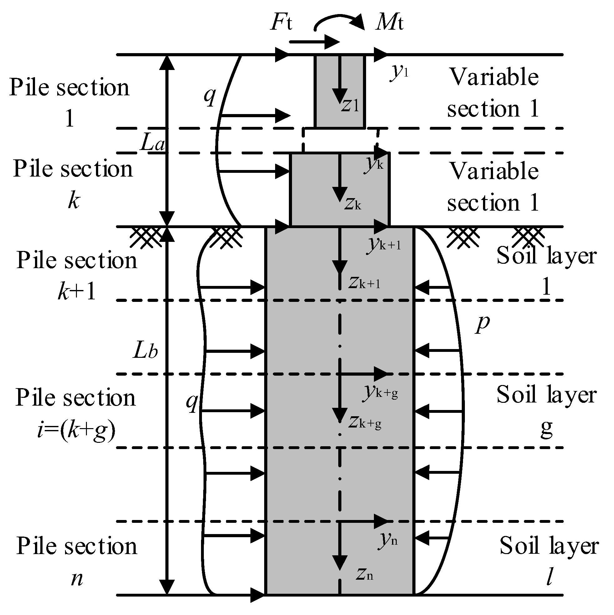
Figure 1. Analysis model of passive pile force in a layered foundation.
Buildings 14 01448 g001
Figure 2. Schematic diagram of force analysis of pile elements.
Buildings 14 01448 g002
Figure 3. The calculation flowchart.
Buildings 14 01448 g003
Figure 4. The lateral loading test.
Buildings 14 01448 g004
Figure 5. Bending moment comparison between the piles.
Buildings 14 01448 g005
Figure 6. Shear force and angle of each pile section.
Buildings 14 01448 g006
Figure 7. Neutral shaft angles of the piles’ cross sections.
Buildings 14 01448 g007
Figure 8. Bending moment comparison.
Buildings 14 01448 g008
Figure 9. Total rotation and shear angle of the cross section.
Buildings 14 01448 g009
Figure 10. Normalized load–displacement curves.
Buildings 14 01448 g010
Figure 11. Comparison of the pile-top displacement data.
Buildings 14 01448 g011
Figure 12. Comparison of neutral shaft angles at the pile tops.
Buildings 14 01448 g012
Figure 13. The shear angles of the pile tops, accounting for the proportion of the total rotation.
Buildings 14 01448 g013
Table 1. Test model pile parameters.
Mode PileL (m)La (m)t (m)EI (kN·m2)Fh (kN)
A0.60.080.0010.6840.0628
B0.70.080.0010.6840.0849
Table 2. Pile lengths and pile diameters.
T0.150.450.75
Pile length/m1901401108045256346372715.48.53827.722.316.29.25.1
Pile diameter/m128642112864211286421
L/D ratio15.8317.518.32022.5255.255.756.176.757.78.53.173.463.724.054.65.1
Disclaimer/Publisher’s Note: The statements, opinions and data contained in all publications are solely those of the individual author(s) and contributor(s) and not of MDPI and/or the editor(s). MDPI and/or the editor(s) disclaim responsibility for any injury to people or property resulting from any ideas, methods, instructions or products referred to in the content.