
Analysis and Enlightenment on the Relationships between Two Kinds of Cutter Life Evaluation Indexes and Installation Radius: A Case Study


Abstract
1. Introduction
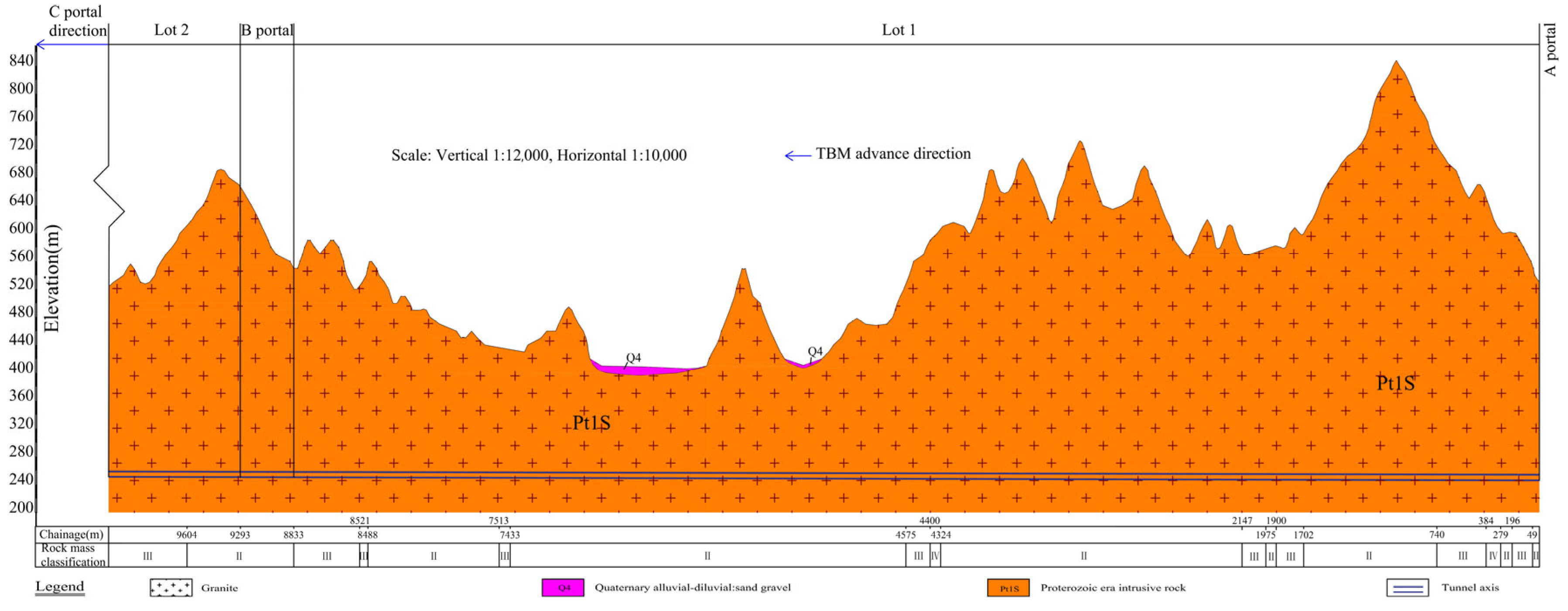
2. Engineering and Equipment Overview
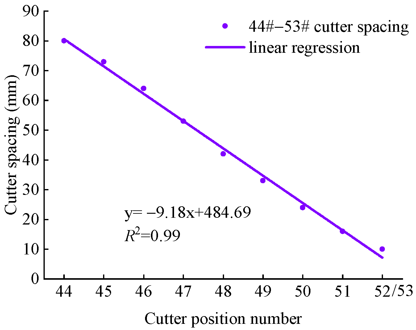
3. Data Acquisition
4. Analysis of the Cutter Life Evaluation Indexes Based on the Radial Wear Extent of Cutter Rings
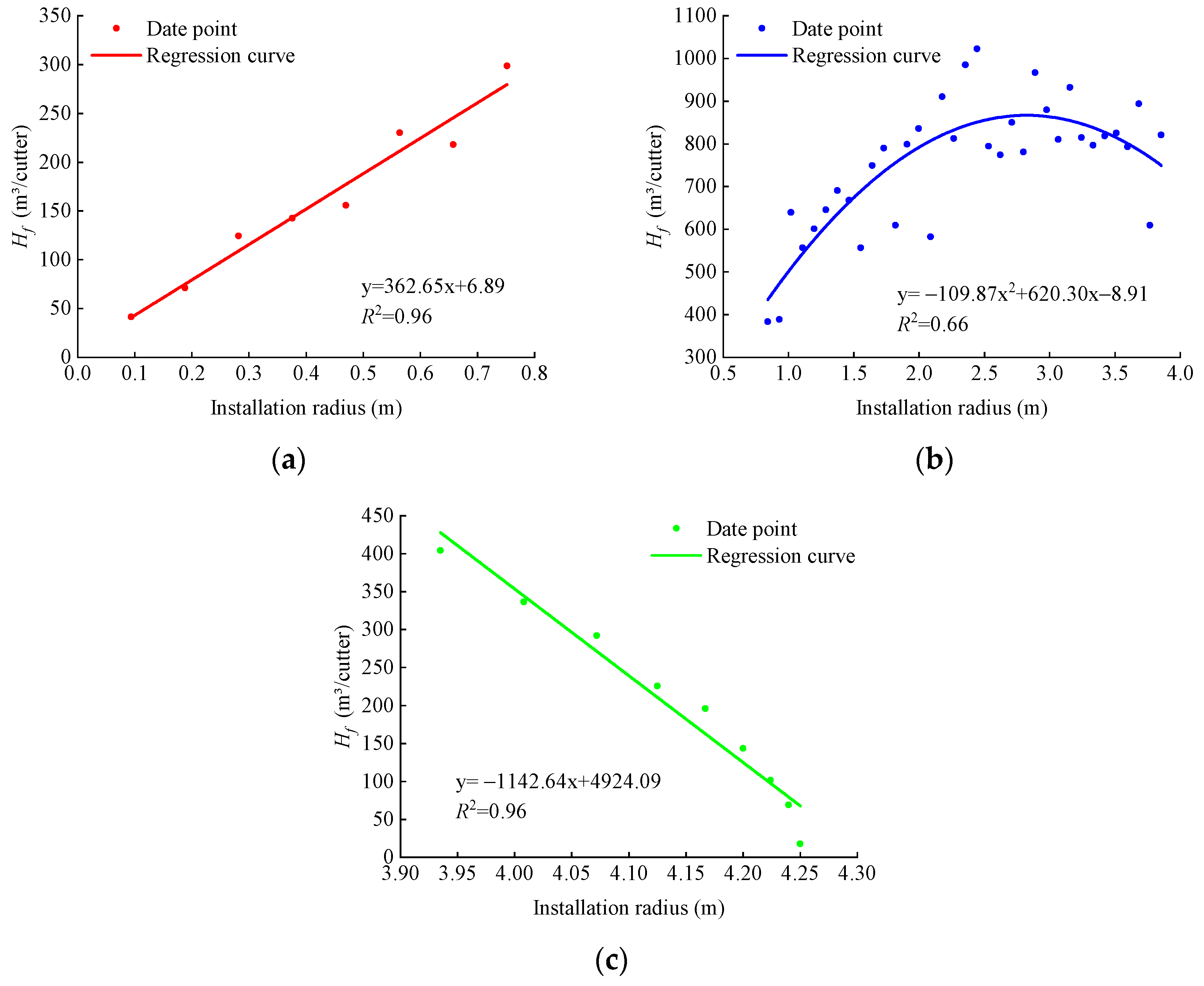
5. Analysis of the Cutter Life Evaluation Indexes Based on the Replacement Number of Cutter Rings
6. Comparison and Enlightenment
7. Conclusions
- (1)
- The regression relationships between the two kinds of cutter life evaluation indexes and installation radius are quite different and mainly present linear functions and quadratic functions. It should be pointed out that the regression relationships obtained in this study are only applicable to projects with similar rock mass conditions and machine specifications but the idea of establishing the empirical relationship between cutter life evaluation index and installation radius by using the regression analysis method is also applicable to other TBM projects;
- (2)
- The above regression relationships are affected by many factors, including wear type, installation angle, cutter spacing, influence width, and allowable limit wear extent of cutter rings. In addition, they are also related to the thrust distribution on the cutter head, which needs further study;
- (3)
- Considering the calculation accuracy of the evaluation index and the actual working conditions of the disc cutter, ignoring the influence of tunnel diameter, it is recommended to preferentially choose the radial wear extent of cutter rings per unit rolling distance Ki as the evaluation index of cutter life.
Author Contributions
Funding
Data Availability Statement
Acknowledgments
Conflicts of Interest
References
- Liu, Q.S.; Huang, X.; Gong, Q.M.; Du, L.J.; Pan, Y.C.; Liu, J.P. Application and development of hard rock TBM and its prospect in China. Tunn. Undergr. Space Technol. 2016, 57, 33–46. [Google Scholar] [CrossRef]
- Liu, Q.S.; Liu, J.P.; Pan, Y.C.; Zhang, X.P.; Peng, X.X.; Gong, Q.M.; Du, L.J. A wear rule and cutter life prediction model of a 20-in. TBM cutter for granite: A case study of a water conveyance tunnel in China. Rock Mech. Rock Eng. 2017, 50, 1303–1320. [Google Scholar] [CrossRef]
- Liu, Q.S.; Liu, J.P.; Pan, Y.C.; Kong, X.X.; Hong, K.R. A case study of TBM performance prediction using a Chinese rock mass classification system—Hydropower Classification (HC) method. Tunn. Undergr. Space Technol. 2017, 65, 140–154. [Google Scholar] [CrossRef]
- Huang, X.; Liu, Q.S.; Shi, K.; Pan, Y.C.; Liu, J.P. Application and prospect of hard rock TBM for deep roadway construction in coal mines. Tunn. Undergr. Space Technol. 2018, 73, 105–126. [Google Scholar] [CrossRef]
- Huang, X.; Zhang, Q.T.; Liu, Q.S.; Liu, X.W.; Liu, B.; Wang, J.J.; Yin, X. A real-time prediction method for tunnel boring machine cutter-head torque using bidirectional long short-term memory networks optimized by multi-algorithm. J. Rock Mech. Geotech. Eng. 2022, 14, 798–812. [Google Scholar] [CrossRef]
- Gao, B.Y.; Wang, R.R.; Lin, C.J.; Guo, X.; Liu, B.; Zhang, W.A. TBM penetration rate prediction based on the long short-term memory neural network. Undergr. Space 2021, 6, 718–731. [Google Scholar] [CrossRef]
- Liu, B.L.; Yang, H.Q.; Karekal, S. Reliability analysis of TBM disc cutters under different conditions. Undergr. Space 2021, 6, 142–152. [Google Scholar] [CrossRef]
- Wu, Z.J.; Wei, R.L.; Chu, Z.F.; Liu, Q.S. Real-time rock mass condition prediction with TBM tunneling big data using a novel rock-machine mutual feedback perception method. J. Rock Mech. Geotech. Eng. 2021, 13, 1311–1325. [Google Scholar] [CrossRef]
- Hou, S.K.; Liu, Y.R.; Yang, Q. Real-time prediction of rock mass classification based on TBM operation big data and stacking technique of ensemble learning. J. Rock Mech. Geotech. Eng. 2022, 14, 123–143. [Google Scholar] [CrossRef]
- Jiang, Y.L.; Zeng, J.J.; Xu, C.J.; Xiong, F.Y.; Pan, Y.C.; Chen, X.S.; Lei, Z.X. Experimental study on TBM cutter penetration damage process of highly abrasive hard rock pre-cut by high-pressure water jet. Bull. Eng. Geol. Environ. 2022, 81, 511. [Google Scholar] [CrossRef]
- Liu, B.L.; Yang, H.Q.; Wang, G.L.; Gao, H.C.; Ren, J.X. Prediction of disc cutter wear considering the argillization effect. Int. J. Geomech. 2023, 23, 04023062. [Google Scholar] [CrossRef]
- Yu, H.G.; Qin, C.J.; Tao, J.F.; Liu, C.L.; Liu, Q.S. A multi-channel decoupled deep neural network for tunnel boring machine torque and thrust prediction. Tunn. Undergr. Space Technol. 2023, 133, 104949. [Google Scholar] [CrossRef]
- Yang, T.T. Investigation on Disaster Mechanism of Diversion Tunnel Induced by Gripper TBM in Hydrokarst Erosion Stratum and Engineering Measures. Buildings 2024, 14, 625. [Google Scholar] [CrossRef]
- Zhang, Y.; Chen, J.Q.; Han, S.; Li, B. Big Data-Based Performance Analysis of Tunnel Boring Machine Tunneling Using Deep Learning. Buildings 2022, 12, 1567. [Google Scholar] [CrossRef]
- Ge, Y.H.; Liu, Y.B.; Lin, P.; Xu, Z.H. Effects of rock properties on the wear of TBM disc cutter: A case study of the Yellow River diversion project, China. Int. J. Geomech. 2022, 22, 04022011. [Google Scholar] [CrossRef]
- Rong, X.N.; Lu, H.; Wang, M.Y.; Wen, Z.; Rong, X. Cutter wear evaluation from operational parameters in EPB tunneling of Chengdu Metro. Tunn. Undergr. Space Technol. 2019, 93, 103043. [Google Scholar] [CrossRef]
- Yang, H.Q.; Wang, H.; Zhou, X.P. Analysis on the Rock–Cutter Interaction Mechanism During the TBM Tunneling Process. Rock Mech. Rock Eng. 2016, 49, 1073–1090. [Google Scholar] [CrossRef]
- Zhang, X.P.; Ji, P.Q.; Liu, Q.S.; Liu, Q.; Zhang, Q.; Peng, Z.H. Physical and numerical studies of rock fragmentation subject to wedge cutter indentation in the mixed ground. Tunn. Undergr. Space Technol. 2018, 71, 354–365. [Google Scholar] [CrossRef]
- Ling, X.Z.; Kong, X.X.; Tang, L.; Cong, S.Y.; Tang, W.C. Preliminary identification of potential failure modes of a disc cutter in soil-rock compound strata: Interaction analysis and case verification. Eng. Fail. Anal. 2022, 131, 105907. [Google Scholar] [CrossRef]
- Barzegari, G.; Khodayari, J.; Rostami, J. Evaluation of TBM cutter wear in Naghadeh water conveyance tunnel and developing a new prediction model. Rock Mech. Rock Eng. 2021, 54, 6281–6297. [Google Scholar] [CrossRef]
- Yang, H.Q.; Liu, B.L.; Wang, Y.Q.; Li, C.C. Prediction model for normal and flat wear of disc cutters during TBM tunneling process. Int. J. Geomech. 2021, 21, 06021002. [Google Scholar] [CrossRef]
- Tang, S.H.; Zhang, X.P.; Xie, W.Q.; Liu, Q.S.; Wu, J.; Chen, P. A new evaluation method to quantify the wear failure of irregular cutting tool during shield TBM tunneling in abrasive sandy ground. Eng. Fail. Anal. 2023, 146, 107011. [Google Scholar] [CrossRef]
- Gehring, K. Prognosis of advance rates and wear for underground mechanized excavations. Felsbau 1995, 13, 439–448. (In German) [Google Scholar]
- Farrokh, E.; Kim, D.Y. A discussion on hard rock TBM cutter wear and cutterhead intervention interval length evaluation. Tunn. Undergr. Space Technol. 2018, 81, 336–357. [Google Scholar] [CrossRef]
- Yang, Y.D.; Hong, K.R.; Sun, Z.C.; Chen, K.; Li, F.Y.; Zhou, J.J.; Zhang, B. The derivation and validation of TBM disc cutter wear prediction model. Geotech. Geol. Eng. 2018, 36, 3391–3398. [Google Scholar] [CrossRef]
- Lan, H.; Xia, Y.M.; Miao, B.; Fu, J.; Ji, Z.Y. Prediction model of wear rate of inner disc cutter of engineering in Yinsong, Jilin. Tunn. Undergr. Space Technol. 2020, 99, 103338. [Google Scholar] [CrossRef]
- Bruland, A. Hard Rock Tunnel Boring. Ph.D. Thesis, Norwegian University of Science and Technology, Trondheim, Norway, 1998. [Google Scholar]
- Hassanpour, J.; Rostami, J.; Zhao, J.; Azali, S.T. TBM performance and disc cutter wear prediction based on ten years experience of TBM tunnelling in Iran. Geomech. Tunn. 2015, 8, 239–247. [Google Scholar] [CrossRef]
- Hassanpour, J. Development of an empirical model to estimate disc cutter wear for sedimentary and low to medium grade metamorphic rocks. Tunn. Undergr. Space Technol. 2018, 75, 90–99. [Google Scholar] [CrossRef]
- Wang, L.H.; Kang, Y.L.; Zhao, X.J.; Zhang, Q. Disc cutter wear prediction for a hard rock TBM cutterhead based on energy analysis. Tunn. Undergr. Space Technol. 2015, 50, 324–333. [Google Scholar] [CrossRef]
- Ren, D.J.; Shen, S.L.; Arulrajah, A.; Cheng, W.C. Prediction model of TBM disc cutter wear during tunnelling in heterogeneous ground. Rock Mech. Rock Eng. 2018, 51, 3599–3611. [Google Scholar] [CrossRef]
- Huang, Y.J.; Hao, R.J.; Li, J.; Guo, J.G.; Sun, Y.K.; Liu, J.R. Disk cutter wear prediction of TBM considering sliding and rolling friction. Mater. Sci. 2023, 41, 42–56. [Google Scholar] [CrossRef]
- Zhang, Z.H.; Aqeel, M.; Li, C.; Sun, F. Theoretical prediction of wear of disc cutters in tunnel boring machine and its application. J. Rock Mech. Geotech. Eng. 2019, 11, 111–120. [Google Scholar] [CrossRef]
- Yu, H.G.; Tao, J.F.; Huang, S.; Qin, C.J.; Xiao, D.Y.; Liu, C.L. A field parameters-based method for real-time wear estimation of disc cutter on TBM cutterhead. Autom. Constr. 2021, 124, 103603. [Google Scholar] [CrossRef]
- Sun, Z.C.; Zhao, H.L.; Hong, K.R.; Chen, K.; Zhou, J.J.; Li, F.Y.; Zhang, B.; Song, F.L.; Yang, Y.D.; He, R.Y. A practical TBM cutter wear prediction model for disc cutter life and rock wear ability. Tunn. Undergr. Space Technol. 2019, 85, 92–99. [Google Scholar] [CrossRef]
- Farrokh, E. Cutter change time and cutter consumption for rock TBMs. Tunn. Undergr. Space Technol. 2021, 114, 104000. [Google Scholar] [CrossRef]
- Yang, J.H.; Zhang, X.P.; Ji, P.Q.; Liu, Q.S.; Lu, X.J.; Wei, J.P.; Qi, S.H.; Fang, H.G.; Fang, J.N.; Geng, Y.J. Analysis of disc cutter damage and consumption of TBM1 section on water conveyance tunnel at Lanzhou water source construction engineering. Tunn. Undergr. Space Technol. 2019, 85, 67–75. [Google Scholar] [CrossRef]
- Karami, M.; Zare, S.; Rostami, J. Tracking of disc cutter wear in TBM tunneling: A case study of Kerman water conveyance tunnel. Bull. Eng. Geol. Environ. 2021, 80, 201–219. [Google Scholar] [CrossRef]
- Su, W.L.; Li, X.G.; Jin, D.L.; Yang, Y.; Qin, R.C.; Wang, X.Y. Analysis and prediction of TBM disc cutter wear when tunneling in hard rock strata: A case study of a metro tunnel excavation in Shenzhen, China. Wear 2020, 446–447, 203190. [Google Scholar] [CrossRef]
- Geng, Q.; Bruland, A.; Macias, F.J. Analysis on the Relationship Between Layout and Consumption of Face Cutters on Hard Rock Tunnel Boring Machines (TBMs). Rock Mech. Rock Eng. 2021, 54, 279–297. [Google Scholar] [CrossRef]
- Zhang, Z.Q.; Zhang, K.J.; Dong, W.J.; Zhang, B. Study of Rock-Cutting Process by Disc Cutters in Mixed Ground based on Three-dimensional Particle Flow Model. Rock Mech. Rock Eng. 2020, 53, 3485–3506. [Google Scholar] [CrossRef]
- Yang, W.K.; Chen, Z.Y.; Wu, G.S.; Xing, H. Probabilistic model of disc-cutter wear in TBM construction: A case study of Chaoer to Xiliao water conveyance tunnel in China. Sci. China Technol. Sci. 2023, 66, 3534–3548. [Google Scholar] [CrossRef]
- Dash, B.; Murthy, V.M.S.R.; Chattopadhyaya, S. Design Aspects Governing Disc Cutters and Cutterheads of Hard Rock TBM—A Review. Min. Metall. Explor. 2024, 41, 219–237. [Google Scholar] [CrossRef]
- Zhou, Z.L.; Tan, Z.S.; Li, Z.L.; Ma, D.; Zhang, L.L. TBM cutter wear under high-strength surrounding rock conditions: A case study from the second phase of the Northern Xinjiang water supply project. Rock Mech. Rock Eng. 2021, 54, 5023–5039. [Google Scholar] [CrossRef]
- Bardhan, A.; Kardani, N.; Guharay, A.; Burman, A.; Samui, P.; Zhang, Y.M. Hybrid ensemble soft computing approach for predicting penetration rate of tunnel boring machine in a rock environment. J. Rock Mech. Geotech. Eng. 2021, 13, 1398–1412. [Google Scholar] [CrossRef]


| No. | Index Type | Cutter Life Evaluation Index | Source |
|---|---|---|---|
| 1 | Indexes based on mass loss of cutter rings | Mass loss of cutter rings per unit rolling distance (mg/m) | [23] |
| 2 | Mass loss of cutter rings per unit rock-breaking volume (mg/m3) | [24] | |
| 3 | Indexes based on radial wear extent of cutter rings | Rock-breaking volume per unit radial wear extent of cutter rings (m3/mm) | [2] |
| 4 | Radial wear extent of cutter rings per unit rolling distance (mm/m) | [25] | |
| 5 | Radial wear extent of cutter rings per unit tunneling distance (mm/m) | [26] | |
| 6 | Indexes based on replacement number of cutter rings | Tunneling distance of a single cutter ring (m/cutter) | [27] |
| 7 | Rolling distance of a single cutter ring (m/cutter) | [28] | |
| 8 | Rock-breaking volume of a single cutter ring (m3/cutter) | [29] | |
| 9 | Indexes based on energy analysis | Accumulative value of disc cutter friction work (J) | [30] |
| 10 | Accumulated wear extent of cutter rings at a single cutter position (mm) | [31] | |
| 11 | Other indexes | Maximum tunneling distance of a cutter ring (m) | [33] |
| 12 | Cutter ring health index | [34] |
| Cutter Life Evaluation Index | Type of Disc Cutter | ||
|---|---|---|---|
| Center Cutter | Face Cutter | Gage Cutter | |
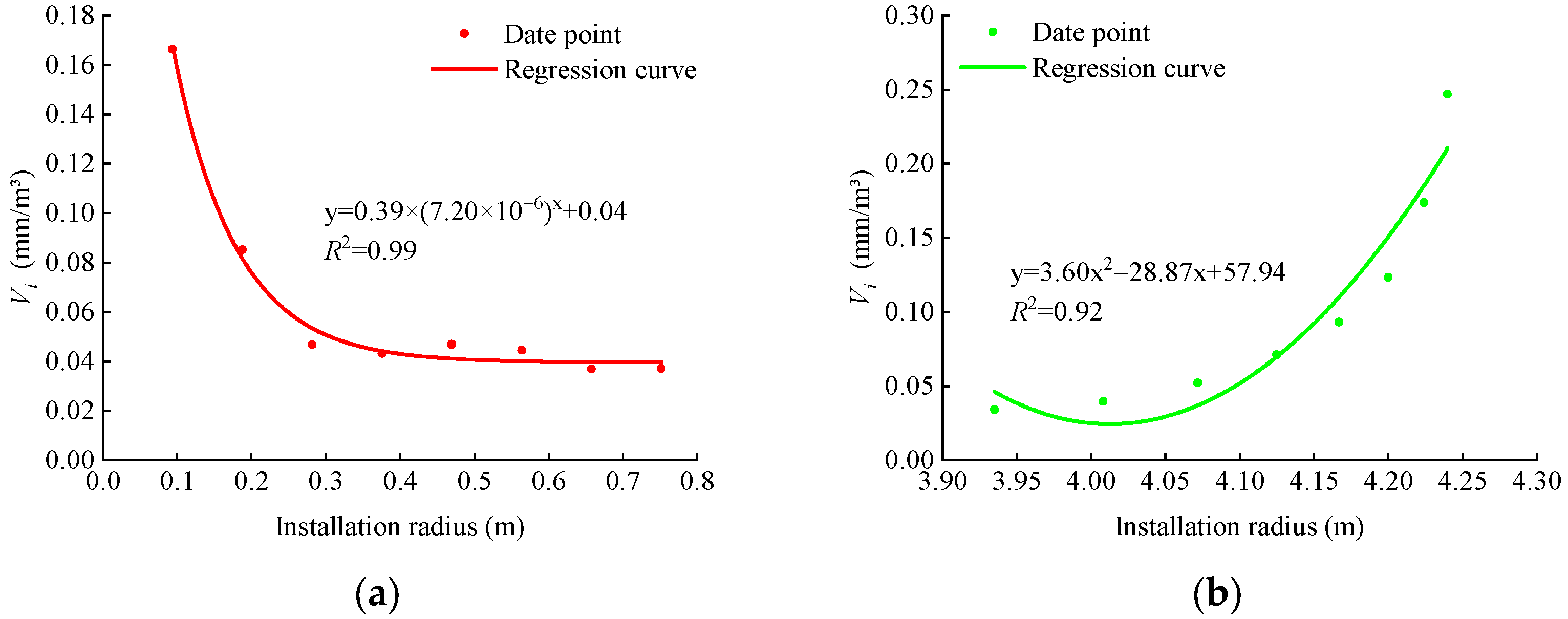
| Ki (mm/m) | Quadratic function | Irrelevant | Quadratic function |
| Vi (mm/m3) | Exponential function | Irrelevant | Quadratic function |
| Li (mm/m) | Linear function (increases) | Linear function (increase) | Quadratic function |
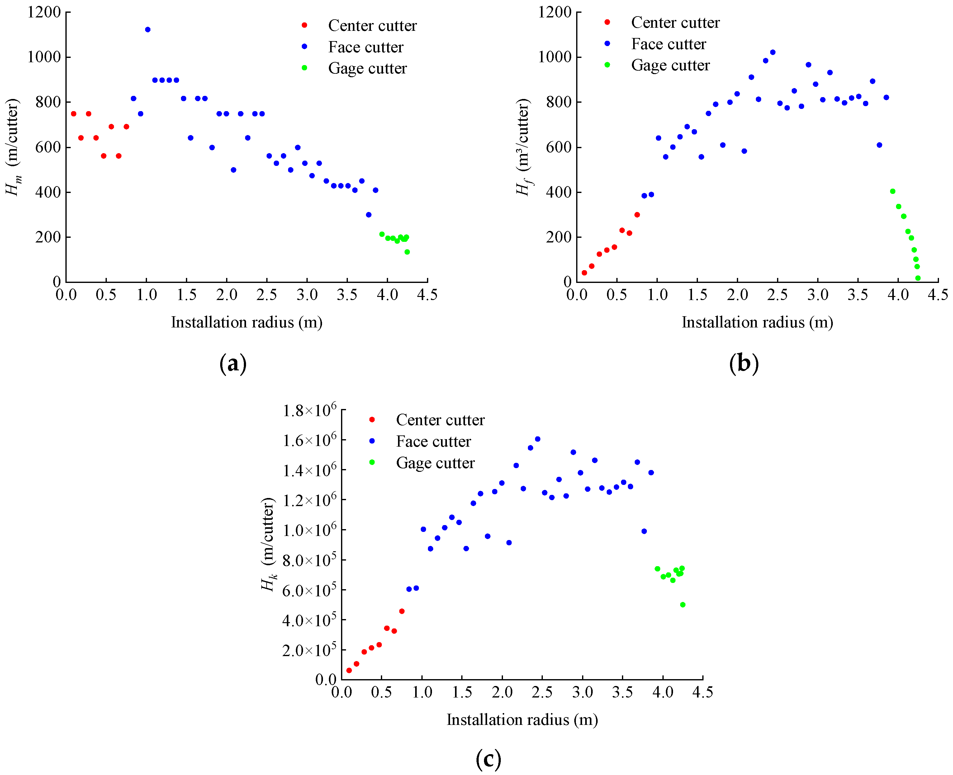
| Hm (m/cutter) | / | Linear function (decrease) | Irrelevant |
| Hf (m3/cutter) | Linear function (increases) | Quadratic function | Linear function (decrease) |
| Hk (m/cutter) | Linear function (increases) | Quadratic function | Irrelevant |
Disclaimer/Publisher’s Note: The statements, opinions and data contained in all publications are solely those of the individual author(s) and contributor(s) and not of MDPI and/or the editor(s). MDPI and/or the editor(s) disclaim responsibility for any injury to people or property resulting from any ideas, methods, instructions or products referred to in the content. |
© 2024 by the authors. Licensee MDPI, Basel, Switzerland. This article is an open access article distributed under the terms and conditions of the Creative Commons Attribution (CC BY) license (https://creativecommons.org/licenses/by/4.0/).
Share and Cite
Liu, J.; He, T.; Zhou, Z.; Peng, X.; Pan, Y. Analysis and Enlightenment on the Relationships between Two Kinds of Cutter Life Evaluation Indexes and Installation Radius: A Case Study. Buildings 2024, 14, 1523. https://doi.org/10.3390/buildings14061523
Liu J, He T, Zhou Z, Peng X, Pan Y. Analysis and Enlightenment on the Relationships between Two Kinds of Cutter Life Evaluation Indexes and Installation Radius: A Case Study. Buildings. 2024; 14(6):1523. https://doi.org/10.3390/buildings14061523
Chicago/Turabian StyleLiu, Jianping, Tiankui He, Zhijia Zhou, Xingxin Peng, and Yucong Pan. 2024. "Analysis and Enlightenment on the Relationships between Two Kinds of Cutter Life Evaluation Indexes and Installation Radius: A Case Study" Buildings 14, no. 6: 1523. https://doi.org/10.3390/buildings14061523
APA StyleLiu, J., He, T., Zhou, Z., Peng, X., & Pan, Y. (2024). Analysis and Enlightenment on the Relationships between Two Kinds of Cutter Life Evaluation Indexes and Installation Radius: A Case Study. Buildings, 14(6), 1523. https://doi.org/10.3390/buildings14061523