Article

Analysis and Enlightenment on the Relationships between Two Kinds of Cutter Life Evaluation Indexes and Installation Radius: A Case Study

1
College of Water Conservancy and Hydropower Engineering, Sichuan Agricultural University, Ya’an 625014, China
2
China Railway 11th Bureau Group Fourth Engineering Co., Ltd., Wuhan 430074, China
3
Key Laboratory of Safety for Geotechnical and Structural Engineering of Hubei Province, School of Civil Engineering, Wuhan University, Wuhan 430072, China
*
Author to whom correspondence should be addressed.
Buildings 2024, 14(6), 1523; https://doi.org/10.3390/buildings14061523
Submission received: 20 March 2024 / Revised: 10 May 2024 / Accepted: 22 May 2024 / Published: 24 May 2024

Abstract

:
Accurate evaluation of cutter life at different cutter positions on the cutter head is helpful to determine the time of cutter change and reduce the time of cutter wear measurement, which is of great significance to improve the tunneling efficiency of tunnel boring machine (TBM) projects. Unfortunately, there is no unified cutter life evaluation index now. The field data of cutter wear are collected from a section of a long TBM tunneling water conveyance tunnel in China. Two kinds of cutter life evaluation indexes (based on the radial wear extent of cutter rings and replacement number of cutter rings) are selected and the variation rule between these two kinds of indexes with cutter installation radius is statistically analyzed. The results show that the regression relationships between the two kinds of cutter life evaluation indexes and installation radius mainly present linear functions and quadratic functions. Those regression relationships are affected by factors such as wear type, installation angle, cutter spacing, influence width, and allowable limit wear extent of cutter rings. Considering the calculation accuracy of the evaluation index, the actual working conditions of the disc cutter, and ignoring the influence of tunnel diameter, it is recommended to preferentially choose the radial wear extent of cutter rings per unit rolling distance as the evaluation index of cutter life. The research results can provide a reference for the selection of cutter life evaluation index, prediction of disc cutter life at different cutter positions, and establishment of cutter life prediction mode.

1. Introduction

TBMs (tunnel boring machines) have been widely used to construct long-distance tunnels due to their high efficiency, good stability control of surrounding rock, and low labor intensity [1,2,3,4,5,6,7,8,9,10,11,12,13,14]. Inevitably, the rock–machine interaction during TBM tunneling leads to the continuous wear of cutter rings. In order to ensure the efficiency of TBM tunneling, the cutter inspectors need to accurately assess the current wear condition of cutter rings and timely replace the cutter rings worn to their limits or appear abnormal wear [15,16,17,18,19]. The daily inspection and replacement of disc cutters is an extremely time-consuming process, which seriously affects the construction speed [20,21,22]. Therefore, an accurate assessment of the wear extent of rings at different cutter positions is helpful for the daily management and optimization of TBM projects. Cutter wear is a direct reflection of the rock–machine interaction after a long time, which can be expressed as the loss of the cutter itself (such as mass loss, radial wear of cutter ring, number of cutter replacements, etc.). Some parameters related to the cutter or rock-breaking effect (such as cutter rolling distance, rock-breaking volume, tunneling distance, etc.) can be obtained during TBM tunneling. The ratio of the two can be defined as the cutter life evaluation index. The selection of the cutter life evaluation index is closely related to the accuracy of cutter life prediction, which further affects the accuracy of construction cost prediction for TBM projects. Unfortunately, there is no unified cutter life evaluation index. Considering different perspectives, different researchers have selected different factors to evaluate the disc cutter’s life.
Some researchers suggested that the disc cutter life can be measured by the mass loss of cutter rings. For example, Gehring [23] evaluated the disc cutter life using the mass loss of cutter rings when a disc cutter rolls at a unit distance on the tunnel face. On the basis of Gehring’s research work, considering the influence of tunnel diameter, Farrokh et al. [24] proposed to replace the rolling distance with the rock-breaking volume and used the mass loss of cutter rings per unit rock-breaking volume to evaluate the disc cutter life.
Some researchers suggested that the disc cutter life can be measured by the radial wear extent of cutter rings. For example, Liu et al. [2] evaluated the disc cutter life using the rock-breaking volume per unit radial wear extent of cutter rings. Yang et al. [25] evaluated the disc cutter life with the radial wear extent of cutter rings per unit rolling distance. Lan et al. [26] evaluated the disc cutter life of the face cutters with the radial wear extent of cutter rings per unit tunneling distance.
Some researchers suggested that the disc cutter life can be measured by the replacement number of cutter rings. For example, Bruland [27] evaluated the disc cutter life using the tunneling distance of a single cutter ring. Hassanpour et al. [28,29] evaluated the disc cutter life using the rolling distance of a single cutter ring or the rock-breaking volume of a single cutter ring.
Some researchers thought that the cutter ring wear is an intuitive embodiment of the accumulation and transformation of friction energy through analyzing the friction process between the disc cutter and surrounding rock. Wang et al. [30] deduced the cutter energy equation and evaluated the disc cutter life by analyzing the relationships between the cutter’s working state and the upper and lower limit curves of the energy equation. Ren et al. [31] and Huang et al. [32] assumed that there is a linear relationship between the wear extent of cutter rings and the friction energy and deduced the empirical coefficients between the friction work of cutter rings, the wear extent of cutter rings, and the friction energy and suggested that the disc cutter life can be evaluated using the accumulated wear extent of cutter rings at a single cutter position.
In addition, Zhang et al. [33] derived the maximum tunneling distance of a cutter ring and verified the practicability of the formula by using the field data of the Qinling Tunnel. Yu et al. [34] defined a new cutter ring health index, which can evaluate the disc cutter life in real-time during TBM tunneling, and verified the effectiveness of the method by using the data set constructed by the field data of Mumbai Metro Line 3.
The above cutter life evaluation indexes are summarized in Table 1. It can be seen that the above cutter life evaluation indexes are established based on different perspectives. Most of these indexes regard the cutter head as a whole and count the overall radial wear extent of cutter rings or the overall replacement number of cutter rings at all cutter positions on the cutter head, which cannot accurately predict the disc cutter life at a certain cutter position. At the same time, different researchers selected a single cutter life evaluation index according to their own needs and did not make a comparison of the above indexes. At present, the existing researches mainly realize the evaluation of cutter life through the method of regression analysis by collecting geological data and cutter wear data on site. Therefore, based on the field data collected from a section of a long TBM tunneling water conveyance tunnel in China, this paper selects two kinds of commonly used cutter life evaluation indexes (based on radial wear extent of cutter rings and replacement number of cutter rings) and obtains the variation rule between these two kinds of indexes with the cutter installation radius. Meanwhile, the two kinds of cutter life evaluation indexes are compared briefly. The research results can provide a reference for the selection of the cutter life evaluation index, prediction of disc cutter life at different cutter positions, and establishment of the cutter life prediction model.

2. Engineering and Equipment Overview

The cutter wear data are obtained from a certain section of a long water conveyance tunnel in China, with a total length of about 10 km and an excavation diameter of 8.50 m. The longitudinal geological profile along the studied tunnel is shown in Figure 1. The lithology of the tunnel is giant porphyritic granite, with a uniaxial compressive strength (UCS) range of 40–100 MPa and a Cerchar abrasivity index (CAI) range of 2.5–4.5; the overall stability of the surrounding rock is good and the rock mass classification is mainly class II based on the Hydropower Classification (HC) method [3]. A gripper TBM manufactured by Robbins Company is used for the construction of this section. The frontal picture of the cutter head is shown in Figure 2. In order to more intuitively understand the information of disc cutters on the cutter head, the TBM cutter layout diagram can be obtained after the quantization of Figure 2, as shown in Figure 3, including cutter type, cutter diameter, cutter number, cutter spacing, cutter head radius, and allowable limit wear extent of cutter rings (Wmax). The cutter is divided into the center cutter, face cutter, and gage cutter based on the position of the cutter on the cutter head. The cutter number increases gradually with the distance from the cutter to the cutter head center. Cutter spacing refers to the distance between adjacent cutter rings. Wmax refers to the maximum radial wear extent of the cutter ring when the cutter must be replaced.

3. Data Acquisition

After TBM tunneling every day, the cutter inspectors inspect and measure all the cutters on the cutter head during the machine maintenance; the cutter wear measurement method is shown in Figure 4a. The disc cutters that reach the allowable limit wear extent of cutter rings or appear abnormal wear are replaced. The normal wear along the circumferential direction of the cutter ring is shown in Figure 4b. At the same time, the radial wear extent and replacement situation of cutter rings at each cutter position are recorded in the cutter maintenance record sheet. Considering that the radial wear extent and replacement number of cutter rings are both accurate values recorded in the field, the widely recognized index in the industry should be selected. Therefore, two kinds of cutter life evaluation indexes (based on the radial wear extent of cutter rings and the replacement number of cutter rings) are selected.
In addition, the TBM drivers fill out a daily TBM tunneling report to record information such as the TBM’s daily tunneling distance, the penetration of the cutter head per rotation, and the thrust value and the torque value during a stable period of each stroke. Through collecting data such as the cutter maintenance record sheets and the daily TBM tunneling reports, combined with the cutter information in Figure 3, a targeted statistical analysis of field data is performed to obtain the radial wear extent of cutter rings and the replacement number of cutter rings at different cutter positions, as shown in Figure 5. It can be seen from Figure 5 that the number of the replaced rings and the accumulated radial wear extent of cutter rings both increase with the increase in installation radius for the whole cutter head, which is consistent with the results of existing studies [35,36,37,38,39,40,41].

4. Analysis of the Cutter Life Evaluation Indexes Based on the Radial Wear Extent of Cutter Rings

In the process of TBM tunneling, the movement track of every disc cutter on the cutter head is helical, namely with a combination of cutter head rotation and a forward advance. The length of the helical is the rolling distance of the cutter. Under the action of thrust, the cutter penetrates and breaks the rock on the tunnel face. The rock-breaking volume and tunneling distance are formed naturally during cutter wear. Therefore, there are three cutter life evaluation indexes based on radial wear extent of cutter rings, namely, the average radial wear extent of cutter rings per unit rolling distance, the average radial wear extent of cutter rings per unit rock-breaking volume, and the average radial wear extent of cutter rings per unit tunneling distance. The calculation formulas are shown in Equations (1)–(3) [2,25,26].
K i = M i 2 π R i L / P
V i = M i 2 π R i S i L
L i = M i L
where Ki is the average radial wear extent of cutter rings per unit rolling distance at the i’th cutter position, mm/m; Mi is the accumulated radial wear extent of cutter rings at the i’th cutter position, mm; Ri is the installation radius of disc cutter at the i’th cutter position, m; L is the TBM tunneling distance, m; P is the average penetration of the cutter head per revolution, mm/r; Vi is the average radial wear extent of cutter rings per unit rock-breaking volume at the i’th cutter position, mm/m3; Si is the influence width of disc cutter at the i’th cutter position, m, S i = R i + 1 R i 1 2 ; Ri+1 is the installation radius of disc cutter at the i + 1’th cutter position, m; Ri−1 is the installation radius of disc cutter at the i − 1’th cutter position, m; and Li is the average radial wear extent of cutter rings per unit tunneling distance at the i’th cutter position, mm/m.
After statistical analysis and calculation of the collected data, the relationships between the three indexes and the cutter installation radius are shown in Figure 6.
It can be seen from Figure 6a that the data at 1# and 2# cutter positions are extraordinarily different from the data at other cutter positions. The center cutter will be jammed even if the center cutter diameter of small cutter spacing is large and abnormal wear (i.e., slip wear) is much larger than normal wear [42,43]. These two points are regarded as abnormal points and are not considered in subsequent analysis. The face cutters are almost subjected to primary wear, the cutter wear rates are relatively uniform, and the corresponding data points fluctuate near a horizontal line, which can be considered in light of the fact that Ri has no effect on Ki. It is recommended that Ri should not be included in the input parameters when developing the face cutter life prediction model. In order to further study the relationships between Ri and Ki at the center cutter positions and the gage cutter positions, five different regression models (linear regression, exponential regression, power regression, logarithmic regression, and polynomial regression) were used for classified regression. Regression analysis can not only obtain the functional relationship between the dependent variable and independent variable but also obtain the degree of correlation. The optimal regression models are shown in Figure 7.
It can be seen from Figure 7 that the relationships between Ri and Ki for the center cutter and gage cutter are both quadratic functions. The center cutters are mainly affected by the sliding wear for their small installation radius and the influence degree decreases with the increase in installation radius, so Ki decreases with the increase in Ri. For the gage cutters, the rolling path of the disc cutter gradually increases with the increase in installation radius but the installation angle of the disc cutter also gradually increases with the increase in installation radius. When the installation radius increases to a certain extent, the main influencing factor of cutter ring wear changes from the installation radius to the installation angle and the cutter ring also gradually changes from vertical rock breaking to oblique rock breaking; the contact area with the surrounding rock decreases, which results in a decrease in the cutter ring wear extent [44]. Combined with Equation (1), Ki increases first and then decreases with the increase in Ri.
It can be seen from Figure 6b that the data at the last cutter position (52# and 53# cutters are both located on this cutter position) deviate from the whole. At the last cutter position, only one side of the cutter assists in rock breaking, which undoubtedly increases the wear extent. This data point is regarded as an abnormal point and is not considered in subsequent analysis. It is also found that the corresponding data points of the face cutters fluctuate near a horizontal line, which can be considered in light of the fact that Ri also has no effect on Vi. It is recommended that Ri should not be included in the input parameters when developing the face cutter life prediction model.
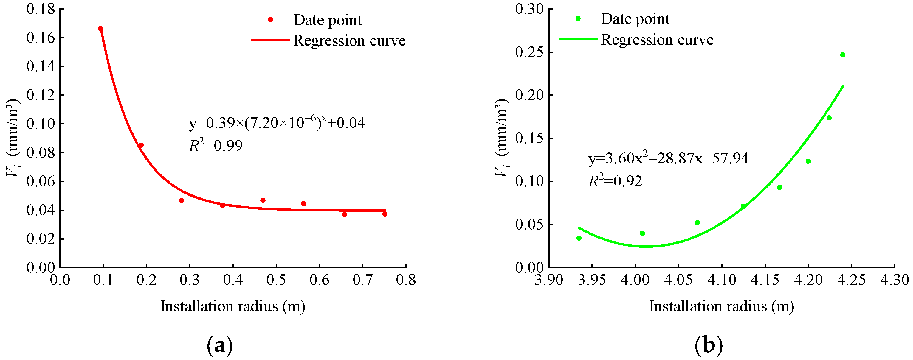
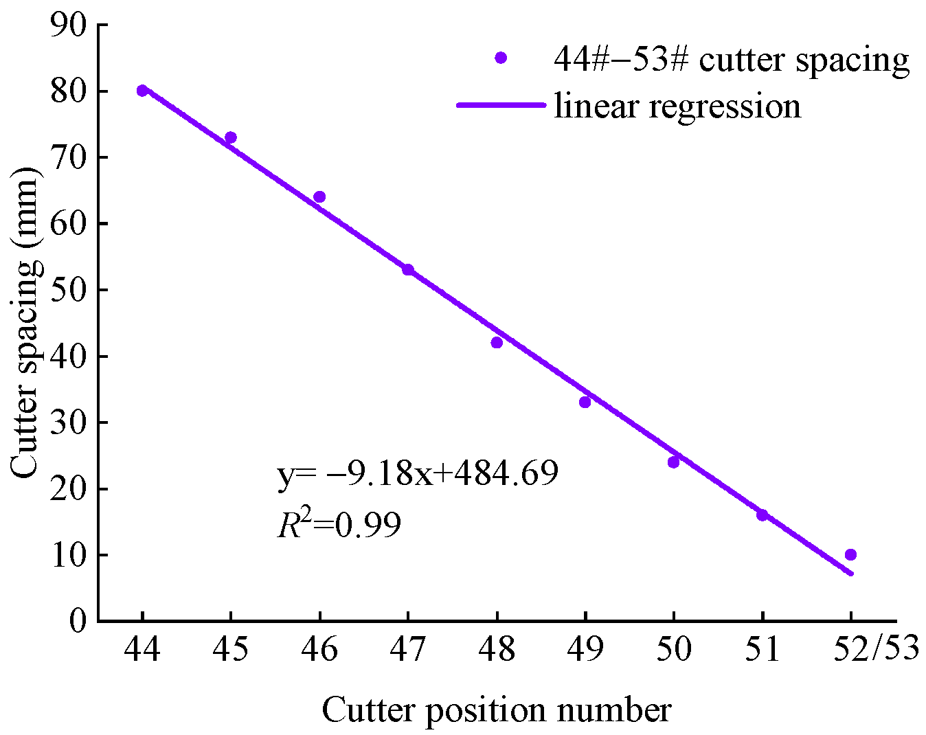
The optimal regression models corresponding to the center cutter and gage cutter are shown in Figure 8. For the center cutters, the data points of the radial wear extent of cutter rings at 1# cutter position and 2# cutter position are very close and those at the 3#~8# cutter position show an approximate linear increase trend (see Figure 5a). The optimal fitting shows that the relationship between Ri and Vi is an exponential function and Vi decreases sharply and then gradually stabilizes with the increase in Ri, as shown in Figure 8a. For the gage cutters, with the increase in installation radius, the radial wear extent of cutter rings increases first and then decreases (see Figure 5a) but the corresponding cutter spacing shows a linear decreasing trend, as shown in Figure 9. The optimal fitting shows that the relationship between Ri and Vi is a quadratic function and Vi gradually increases with the increase in Ri and the rising rate gradually increases, as shown in Figure 8b.
Combined with Equation (3), it is found that the image shape of Figure 6c is consistent with that of Figure 5a. It can be seen from Figure 6c that there is no abnormal data point and the optimal regression models corresponding to different types of cutters are shown in Figure 10.
For the center cutters and the face cutters, with the increase in installation radius, the distance between the disc cutter and the center of the cutter head increases linearly (see Figure 3). Therefore, after a certain distance of TBM tunneling, the rolling path of the disc cutter also shows a linear growth trend with the increase in installation radius and the radial wear extent of cutter rings increases accordingly. As a consequence, there is a linear function relationship between Li and Ri and Li increases linearly with the increase in Ri, as shown in Figure 10a,b. For the gage cutters, the image shape of Figure 10c is consistent with that of Figure 7b, namely, the radial wear extent of cutter rings is affected by the installation radius and installation angle. The optimal fitting shows that the relationship between Li and Ri is a quadratic function and that Li increases first and then decreases with the increase in Ri.

5. Analysis of the Cutter Life Evaluation Indexes Based on the Replacement Number of Cutter Rings

Similarly, there are three cutter life evaluation indexes based on the replacement number of cutter rings, namely, the average tunneling distance of a single cutter ring, the average rock-breaking volume of a single cutter ring, and the average rolling distance of a single cutter ring. The calculation formulas are shown in Equations (4)–(6) [27,28,29].
H m = L N T B M
H f = 2 π R i S i L N T B M
H k = 2 π R i L / P N T B M
where Hm is the average tunneling distance of a single cutter ring at the i’th cutter position, m/cutter; NTBM is the accumulative number of cutter ring changes at the i’th cutter position when the tunneling distance is L, cuttter; Hf is the average rock-breaking volume of a single cutter ring at the i’th cutter position, m3/cutter; and Hk is the average rolling distance of a single cutter ring at the i’th cutter position, m/cutter.
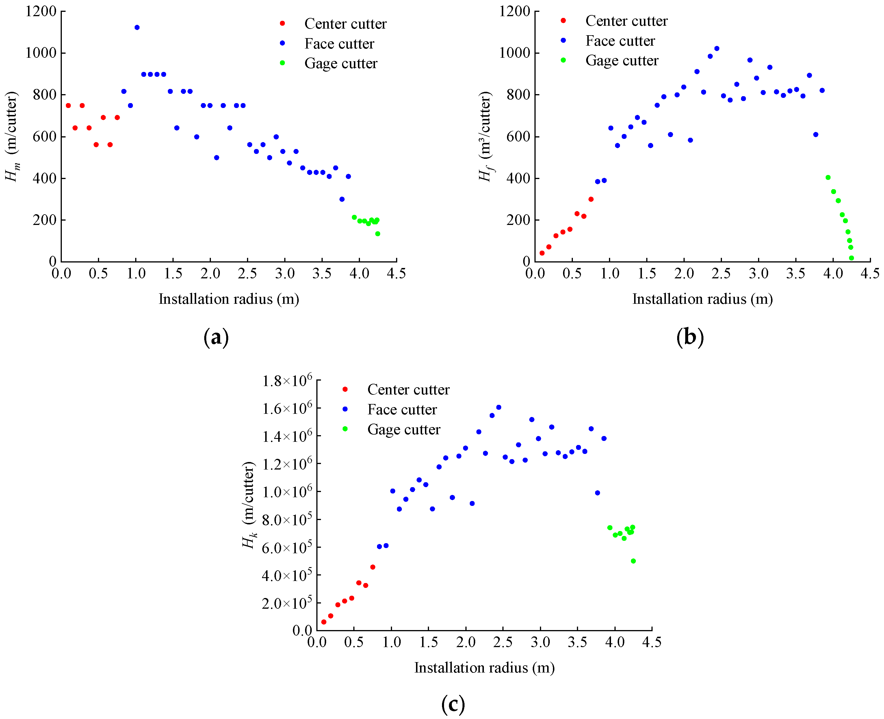
After statistical analysis and calculation of the collected data, the relationships between the three indexes and the cutter installation radius are shown in Figure 11.
It can be seen from Figure 11a that the data points corresponding to the gage cutter positions are almost kept at the same level except the data point corresponding to the last cutter position deviating from the whole, from which it can be considered that Ri has almost no effect on Hm. It is recommended that Ri should not be included in the input parameters when developing the gage cutter life prediction model. The optimal regression models corresponding to the center cutter and face cutter are shown in Figure 12. The center cutters, with double rings, need to be changed at the same time and the data points appear in pairs. The wear mechanism of the center cutters is extremely complicated for their small installation radius. As the R2 is still small, the relationship between Hm and Ri is not obvious even for the optimal quadratic function fitting in Figure 12a. The cutter spacing and the allowable limit for the wear extent of cutter rings are both constant values for the face cutters (see Figure 3) and the rolling distance gradually increases with the increase in installation radius. Therefore, the radial wear extent of cutter rings and the replacement number of cutter rings show an approximate linear increase trend with the increase in installation radius after a certain distance of TBM tunneling (see Figure 5). As a consequence, there is a linear function relationship between Ri and Hm and Hm decreases linearly with the increase in Ri, as shown in Figure 12b.
It can be seen from Figure 11b that the data points corresponding to the face cutters are located above those corresponding to the center cutters and the gage cutters, which indicates that the average rock-breaking volume of a single cutter ring of the face cutter is the highest and confirms that the face cutters are the backbones of rock breaking on the cutter head. The optimal regression models corresponding to different types of cutters are shown in Figure 13.
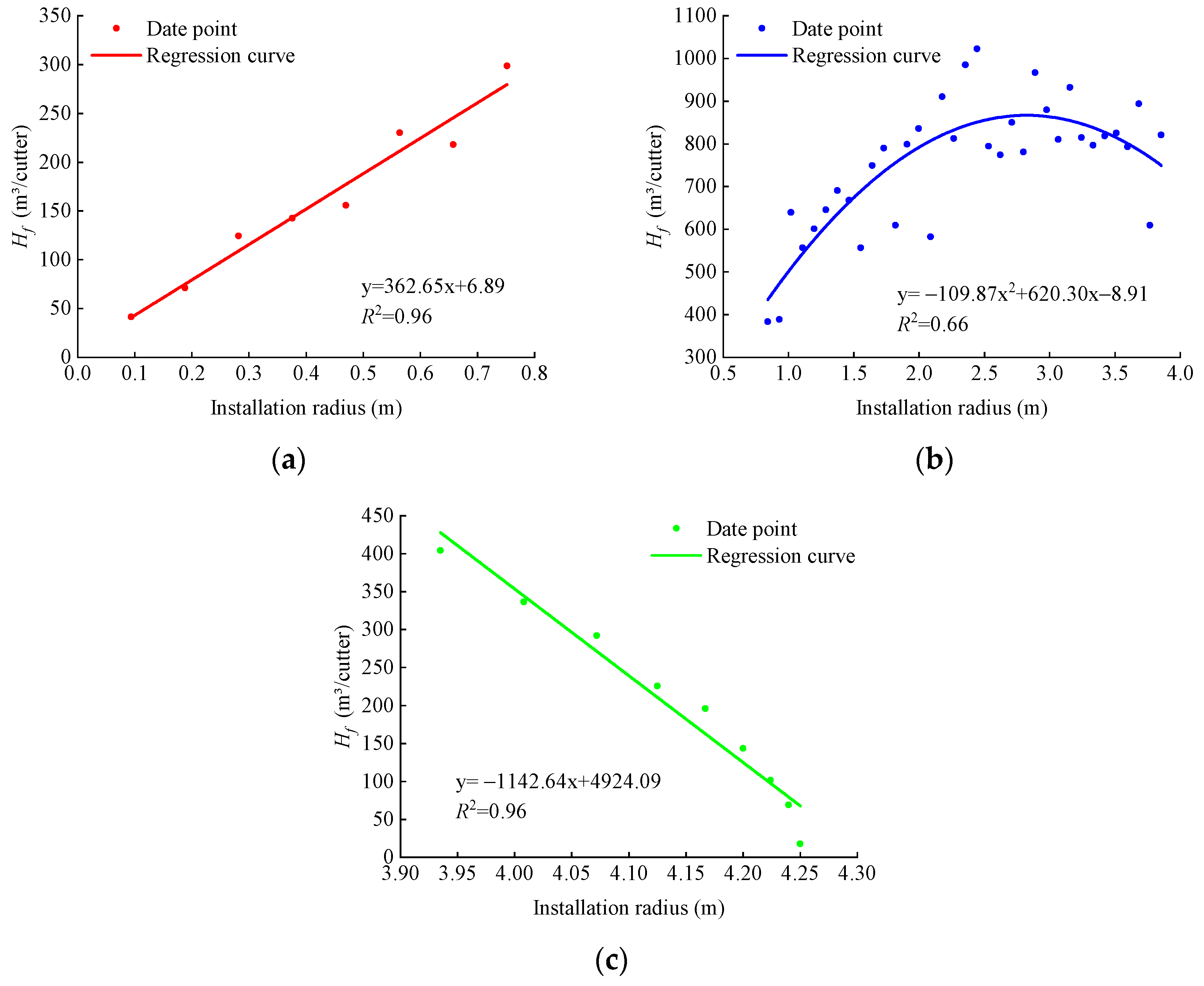
For the center cutters, the cutter spacing is a constant value (see Figure 3), so the influence width is also a constant value and the replacement numbers of cutter rings for different cutter positions are slightly different (between 12 and 16) (see Figure 5b). Combined with Equation (5), it is found that there is a linear function relationship between Ri and Hf that and Hf increases linearly with Ri, as shown in Figure 13a. For the face cutters, the cutter spacing is a constant value (see Figure 3), so the influence width is also a constant value, and the linear growth trend of the replacement number of cutter rings becomes larger near the installation radius of 2.5 m (see Figure 14). The optimal fitting shows that there is a quadratic function relationship between Ri and Hf and Hf increases first and then decreases slowly with the increase in Ri, as shown in Figure 13b. For the gage cutters, the replacement numbers of cutter rings are slightly different (between 42 and 49) (see Figure 5b) except that corresponding to the last cutter position. The installation radius and the influence width are both related to the cutter spacing and the corresponding cutter spacing shows a linear decreasing trend (see Figure 9). Combined with Equation (5), it is found that there is a linear function relationship between Ri and Hf and that Hf decreases linearly with the increase in Ri, as shown in Figure 13c.
Comparing Figure 11b and Figure 11c, it can be seen that the change trend of the corresponding data points of the center cutters and the face cutters are consistent except for the corresponding data points of the gage cutters. This is because Hf also considers the influence of width compared to Hk when comparing Equation (5) with Equation (6) and the influence width is closely related to the cutter spacing. The influence widths corresponding to the center cutters and the face cutters are both a constant value but the influence width corresponding to the gage cutters shows a linear decreasing trend (see Figure 9), which leads to different change trends for the gage cutters. For the center cutters and the face cutters, the functional relationships between Ri and Hk are consistent with those between Ri and Hf, as shown in Figure 15. In addition, it can be seen from Figure 11c that the data points corresponding to the gage cutter positions are almost at the same level except the data point corresponding to the last cutter position deviating from the whole, which can be considered in light of the fact that Ri has almost no effect on Hk. It is recommended that Ri should be not included in the input parameters when developing the gage cutter life prediction model.
Based on the above research results, the regression relationships between the two kinds of cutter life evaluation indexes and installation radius are summarized in Table 2. Those regression relationships are affected by factors such as wear type, installation angle, cutter spacing, influence width, and allowable limit wear extent of the cutter rings. The result helps in the accurate evaluation of cutter life at different cutter positions, guides the replacement time of disc cutters, and reduces the time of cutter wear measurement, which is of great significance in improving the tunneling efficiency of TBM projects. It should be emphasized that cutter wear is very sensitive to the geology, rock type, and mechanical properties along the tunnel axis during TBM tunneling [45]. Therefore, the regression relationships summarized in this paper are applicable to a single lithological condition and similar TBM specifications. If the lithology (or rock abrasiveness) of the tunnel axis changes, the quantitative values of different cutter life evaluation indexes will also change. Considering that the lithology does not change in a short distance along the tunnel axis, it can be considered that the method proposed in this paper of establishing the empirical relationship between cutter life evaluation index and installation radius by using regression analysis is also suitable for other TBM projects. For example, the cutter wear data corresponding to the machine learning period (generally 2 months after TBM tunneling) are excluded. Based on the cutter wear data (such as 2 months) collected corresponding to a certain lithology section, the empirical relationship between the cutter life evaluation index and installation radius is established by using the regression analysis method, which can be used to guide the replacement time of disc cutter in similar lithologic sections in later periods combined with the wear degree and allowable limit wear extent of the cutter ring at different cutter positions. This method can also be used for different lithologic sections of the same tunnel.

6. Comparison and Enlightenment

In general, the radial wear extent and replacement number of cutter rings are both accurate values recorded in the cutter maintenance record sheets. The TBM must be stopped routinely after each 3–4 excavation stroke to inspect the conditions of all disc cutters. If the failed cutter is not replaced in time, the rock-breaking pressure of the adjacent cutter will be increased. The wear extent of adjacent cutters will increase rapidly and the data collected in this paper will also be high. There are two main reasons for cutter replacement, namely, disc cutters reach the allowable limit wear extent of cutter rings or appear abnormal wear. In most cases, however, the radial wear extent of the cutter ring is far from the allowable limit wear extent when the disc cutter is replaced due to abnormal wear, which means that the cutter ring is not fully utilized. Therefore, the index based on the radial wear extent of cutter rings can more accurately characterize the cutter life than the index based on the replacement number of cutter rings.
Considering that cutter wear is an intuitive manifestation of the cutter–rock interaction when the disc cutter invades the rock and rolls on the tunnel face, Ki and Hk are more suitable for the actual working conditions of the disc cutter but the calculation of the rolling distance is related to the tunneling distance and the penetration per revolution. Considering the unevenness of the tunnel face, the change in penetration per rotation in different strokes, and the influence of the unstable stage of a single stroke, there must be some errors in the calculating process of the rolling distance. However, the other four indexes calculated by rock-breaking volume and tunneling distance can be accurately calculated.
The number of disc cutters on the cutter head will increase when increasing the diameter of the TBM (or tunnel) under a given rock condition and the average cutter life represented by Li and Hm will also change. However, with a relatively wider application range, Ki, Vi, Hf, and Hk can be used to compare the cutter life of different diameters of TBM projects to ignore the influence of changing the tunnel diameter.
To sum up, it is recommended to preferentially choose the radial wear extent of cutter rings per unit rolling distance Ki as the evaluation index of cutter life.
One of the tasks of developing a cutter life prediction model using the cutter life evaluation index is to predict the cutter cost. As is well known, a disc cutter consists of many parts, such as a cutter ring, bearings, seals, and so on. Part of the replaced cutters (worn to the limit or appearing abnormal wear) can continue to be used after repair in the repair room on the site. The above two kinds of indexes can only obtain the cost related to the cutter rings. In order to accurately evaluate the cutter cost, it is necessary to know the data such as the utilization ratio of the bearing and cutter ring. Overall, the prediction of cutter costs needs further study.
In future studies, artificial intelligence methods will be used to process the massive data, which can not only exclude outliers in the data set but also derive more accurate results. On this basis, combined with the field data and the recommended indexes, the cutter life prediction model will be developed to provide a reference for TBM engineering construction.

7. Conclusions

The complex interaction between the disc cutter and the surrounding rock on the tunnel face not only increases the difficulty of cutter life prediction but also enriches the diversity of cutter life evaluation indexes. There is no unified cutter life evaluation index at present and the existing cutter life evaluation indexes are briefly summarized in this paper. Based on the field data collected from a section of a long TBM tunneling water conveyance tunnel in China, through statistical analysis and calculation, the regression relationships between the two kinds of cutter life evaluation indexes (based on radial wear extent of cutter rings and replacement number of cutter rings) and the cutter installation radius are obtained and the two kinds of indexes are compared and analyzed briefly. The results are as follows:
(1)
The regression relationships between the two kinds of cutter life evaluation indexes and installation radius are quite different and mainly present linear functions and quadratic functions. It should be pointed out that the regression relationships obtained in this study are only applicable to projects with similar rock mass conditions and machine specifications but the idea of establishing the empirical relationship between cutter life evaluation index and installation radius by using the regression analysis method is also applicable to other TBM projects;
(2)
The above regression relationships are affected by many factors, including wear type, installation angle, cutter spacing, influence width, and allowable limit wear extent of cutter rings. In addition, they are also related to the thrust distribution on the cutter head, which needs further study;
(3)
Considering the calculation accuracy of the evaluation index and the actual working conditions of the disc cutter, ignoring the influence of tunnel diameter, it is recommended to preferentially choose the radial wear extent of cutter rings per unit rolling distance Ki as the evaluation index of cutter life.

Author Contributions

Conceptualization, J.L.; methodology, T.H. and Z.Z.; software, T.H.; investigation, J.L., X.P. and Y.P.; data curation, T.H.; writing—original draft, T.H. and Z.Z.; writing—review and editing, J.L., X.P. and Y.P. All authors have read and agreed to the published version of the manuscript.

Funding

This research was funded by the National Natural Science Foundation of China, grant Nos. 41907242 and 42177140.

Data Availability Statement

Cutter wear data used during the study are confidential in nature and may only be provided with restrictions.

Acknowledgments

Thanks to Sinohydro Bureau 3 Co., Ltd., for their help in the field data collection.

Conflicts of Interest

Xingxin Peng was employed by the China Railway 11th Bureau Group Fourth Engineering Co., Ltd. The remaining authors declare that the research was conducted in the absence of any commercial or financial relationships that could be construed as a potential conflict of interest.

References

  1. Liu, Q.S.; Huang, X.; Gong, Q.M.; Du, L.J.; Pan, Y.C.; Liu, J.P. Application and development of hard rock TBM and its prospect in China. Tunn. Undergr. Space Technol. 2016, 57, 33–46. [Google Scholar] [CrossRef]
  2. Liu, Q.S.; Liu, J.P.; Pan, Y.C.; Zhang, X.P.; Peng, X.X.; Gong, Q.M.; Du, L.J. A wear rule and cutter life prediction model of a 20-in. TBM cutter for granite: A case study of a water conveyance tunnel in China. Rock Mech. Rock Eng. 2017, 50, 1303–1320. [Google Scholar] [CrossRef]
  3. Liu, Q.S.; Liu, J.P.; Pan, Y.C.; Kong, X.X.; Hong, K.R. A case study of TBM performance prediction using a Chinese rock mass classification system—Hydropower Classification (HC) method. Tunn. Undergr. Space Technol. 2017, 65, 140–154. [Google Scholar] [CrossRef]
  4. Huang, X.; Liu, Q.S.; Shi, K.; Pan, Y.C.; Liu, J.P. Application and prospect of hard rock TBM for deep roadway construction in coal mines. Tunn. Undergr. Space Technol. 2018, 73, 105–126. [Google Scholar] [CrossRef]
  5. Huang, X.; Zhang, Q.T.; Liu, Q.S.; Liu, X.W.; Liu, B.; Wang, J.J.; Yin, X. A real-time prediction method for tunnel boring machine cutter-head torque using bidirectional long short-term memory networks optimized by multi-algorithm. J. Rock Mech. Geotech. Eng. 2022, 14, 798–812. [Google Scholar] [CrossRef]
  6. Gao, B.Y.; Wang, R.R.; Lin, C.J.; Guo, X.; Liu, B.; Zhang, W.A. TBM penetration rate prediction based on the long short-term memory neural network. Undergr. Space 2021, 6, 718–731. [Google Scholar] [CrossRef]
  7. Liu, B.L.; Yang, H.Q.; Karekal, S. Reliability analysis of TBM disc cutters under different conditions. Undergr. Space 2021, 6, 142–152. [Google Scholar] [CrossRef]
  8. Wu, Z.J.; Wei, R.L.; Chu, Z.F.; Liu, Q.S. Real-time rock mass condition prediction with TBM tunneling big data using a novel rock-machine mutual feedback perception method. J. Rock Mech. Geotech. Eng. 2021, 13, 1311–1325. [Google Scholar] [CrossRef]
  9. Hou, S.K.; Liu, Y.R.; Yang, Q. Real-time prediction of rock mass classification based on TBM operation big data and stacking technique of ensemble learning. J. Rock Mech. Geotech. Eng. 2022, 14, 123–143. [Google Scholar] [CrossRef]
  10. Jiang, Y.L.; Zeng, J.J.; Xu, C.J.; Xiong, F.Y.; Pan, Y.C.; Chen, X.S.; Lei, Z.X. Experimental study on TBM cutter penetration damage process of highly abrasive hard rock pre-cut by high-pressure water jet. Bull. Eng. Geol. Environ. 2022, 81, 511. [Google Scholar] [CrossRef]
  11. Liu, B.L.; Yang, H.Q.; Wang, G.L.; Gao, H.C.; Ren, J.X. Prediction of disc cutter wear considering the argillization effect. Int. J. Geomech. 2023, 23, 04023062. [Google Scholar] [CrossRef]
  12. Yu, H.G.; Qin, C.J.; Tao, J.F.; Liu, C.L.; Liu, Q.S. A multi-channel decoupled deep neural network for tunnel boring machine torque and thrust prediction. Tunn. Undergr. Space Technol. 2023, 133, 104949. [Google Scholar] [CrossRef]
  13. Yang, T.T. Investigation on Disaster Mechanism of Diversion Tunnel Induced by Gripper TBM in Hydrokarst Erosion Stratum and Engineering Measures. Buildings 2024, 14, 625. [Google Scholar] [CrossRef]
  14. Zhang, Y.; Chen, J.Q.; Han, S.; Li, B. Big Data-Based Performance Analysis of Tunnel Boring Machine Tunneling Using Deep Learning. Buildings 2022, 12, 1567. [Google Scholar] [CrossRef]
  15. Ge, Y.H.; Liu, Y.B.; Lin, P.; Xu, Z.H. Effects of rock properties on the wear of TBM disc cutter: A case study of the Yellow River diversion project, China. Int. J. Geomech. 2022, 22, 04022011. [Google Scholar] [CrossRef]
  16. Rong, X.N.; Lu, H.; Wang, M.Y.; Wen, Z.; Rong, X. Cutter wear evaluation from operational parameters in EPB tunneling of Chengdu Metro. Tunn. Undergr. Space Technol. 2019, 93, 103043. [Google Scholar] [CrossRef]
  17. Yang, H.Q.; Wang, H.; Zhou, X.P. Analysis on the Rock–Cutter Interaction Mechanism During the TBM Tunneling Process. Rock Mech. Rock Eng. 2016, 49, 1073–1090. [Google Scholar] [CrossRef]
  18. Zhang, X.P.; Ji, P.Q.; Liu, Q.S.; Liu, Q.; Zhang, Q.; Peng, Z.H. Physical and numerical studies of rock fragmentation subject to wedge cutter indentation in the mixed ground. Tunn. Undergr. Space Technol. 2018, 71, 354–365. [Google Scholar] [CrossRef]
  19. Ling, X.Z.; Kong, X.X.; Tang, L.; Cong, S.Y.; Tang, W.C. Preliminary identification of potential failure modes of a disc cutter in soil-rock compound strata: Interaction analysis and case verification. Eng. Fail. Anal. 2022, 131, 105907. [Google Scholar] [CrossRef]
  20. Barzegari, G.; Khodayari, J.; Rostami, J. Evaluation of TBM cutter wear in Naghadeh water conveyance tunnel and developing a new prediction model. Rock Mech. Rock Eng. 2021, 54, 6281–6297. [Google Scholar] [CrossRef]
  21. Yang, H.Q.; Liu, B.L.; Wang, Y.Q.; Li, C.C. Prediction model for normal and flat wear of disc cutters during TBM tunneling process. Int. J. Geomech. 2021, 21, 06021002. [Google Scholar] [CrossRef]
  22. Tang, S.H.; Zhang, X.P.; Xie, W.Q.; Liu, Q.S.; Wu, J.; Chen, P. A new evaluation method to quantify the wear failure of irregular cutting tool during shield TBM tunneling in abrasive sandy ground. Eng. Fail. Anal. 2023, 146, 107011. [Google Scholar] [CrossRef]
  23. Gehring, K. Prognosis of advance rates and wear for underground mechanized excavations. Felsbau 1995, 13, 439–448. (In German) [Google Scholar]
  24. Farrokh, E.; Kim, D.Y. A discussion on hard rock TBM cutter wear and cutterhead intervention interval length evaluation. Tunn. Undergr. Space Technol. 2018, 81, 336–357. [Google Scholar] [CrossRef]
  25. Yang, Y.D.; Hong, K.R.; Sun, Z.C.; Chen, K.; Li, F.Y.; Zhou, J.J.; Zhang, B. The derivation and validation of TBM disc cutter wear prediction model. Geotech. Geol. Eng. 2018, 36, 3391–3398. [Google Scholar] [CrossRef]
  26. Lan, H.; Xia, Y.M.; Miao, B.; Fu, J.; Ji, Z.Y. Prediction model of wear rate of inner disc cutter of engineering in Yinsong, Jilin. Tunn. Undergr. Space Technol. 2020, 99, 103338. [Google Scholar] [CrossRef]
  27. Bruland, A. Hard Rock Tunnel Boring. Ph.D. Thesis, Norwegian University of Science and Technology, Trondheim, Norway, 1998. [Google Scholar]
  28. Hassanpour, J.; Rostami, J.; Zhao, J.; Azali, S.T. TBM performance and disc cutter wear prediction based on ten years experience of TBM tunnelling in Iran. Geomech. Tunn. 2015, 8, 239–247. [Google Scholar] [CrossRef]
  29. Hassanpour, J. Development of an empirical model to estimate disc cutter wear for sedimentary and low to medium grade metamorphic rocks. Tunn. Undergr. Space Technol. 2018, 75, 90–99. [Google Scholar] [CrossRef]
  30. Wang, L.H.; Kang, Y.L.; Zhao, X.J.; Zhang, Q. Disc cutter wear prediction for a hard rock TBM cutterhead based on energy analysis. Tunn. Undergr. Space Technol. 2015, 50, 324–333. [Google Scholar] [CrossRef]
  31. Ren, D.J.; Shen, S.L.; Arulrajah, A.; Cheng, W.C. Prediction model of TBM disc cutter wear during tunnelling in heterogeneous ground. Rock Mech. Rock Eng. 2018, 51, 3599–3611. [Google Scholar] [CrossRef]
  32. Huang, Y.J.; Hao, R.J.; Li, J.; Guo, J.G.; Sun, Y.K.; Liu, J.R. Disk cutter wear prediction of TBM considering sliding and rolling friction. Mater. Sci. 2023, 41, 42–56. [Google Scholar] [CrossRef]
  33. Zhang, Z.H.; Aqeel, M.; Li, C.; Sun, F. Theoretical prediction of wear of disc cutters in tunnel boring machine and its application. J. Rock Mech. Geotech. Eng. 2019, 11, 111–120. [Google Scholar] [CrossRef]
  34. Yu, H.G.; Tao, J.F.; Huang, S.; Qin, C.J.; Xiao, D.Y.; Liu, C.L. A field parameters-based method for real-time wear estimation of disc cutter on TBM cutterhead. Autom. Constr. 2021, 124, 103603. [Google Scholar] [CrossRef]
  35. Sun, Z.C.; Zhao, H.L.; Hong, K.R.; Chen, K.; Zhou, J.J.; Li, F.Y.; Zhang, B.; Song, F.L.; Yang, Y.D.; He, R.Y. A practical TBM cutter wear prediction model for disc cutter life and rock wear ability. Tunn. Undergr. Space Technol. 2019, 85, 92–99. [Google Scholar] [CrossRef]
  36. Farrokh, E. Cutter change time and cutter consumption for rock TBMs. Tunn. Undergr. Space Technol. 2021, 114, 104000. [Google Scholar] [CrossRef]
  37. Yang, J.H.; Zhang, X.P.; Ji, P.Q.; Liu, Q.S.; Lu, X.J.; Wei, J.P.; Qi, S.H.; Fang, H.G.; Fang, J.N.; Geng, Y.J. Analysis of disc cutter damage and consumption of TBM1 section on water conveyance tunnel at Lanzhou water source construction engineering. Tunn. Undergr. Space Technol. 2019, 85, 67–75. [Google Scholar] [CrossRef]
  38. Karami, M.; Zare, S.; Rostami, J. Tracking of disc cutter wear in TBM tunneling: A case study of Kerman water conveyance tunnel. Bull. Eng. Geol. Environ. 2021, 80, 201–219. [Google Scholar] [CrossRef]
  39. Su, W.L.; Li, X.G.; Jin, D.L.; Yang, Y.; Qin, R.C.; Wang, X.Y. Analysis and prediction of TBM disc cutter wear when tunneling in hard rock strata: A case study of a metro tunnel excavation in Shenzhen, China. Wear 2020, 446–447, 203190. [Google Scholar] [CrossRef]
  40. Geng, Q.; Bruland, A.; Macias, F.J. Analysis on the Relationship Between Layout and Consumption of Face Cutters on Hard Rock Tunnel Boring Machines (TBMs). Rock Mech. Rock Eng. 2021, 54, 279–297. [Google Scholar] [CrossRef]
  41. Zhang, Z.Q.; Zhang, K.J.; Dong, W.J.; Zhang, B. Study of Rock-Cutting Process by Disc Cutters in Mixed Ground based on Three-dimensional Particle Flow Model. Rock Mech. Rock Eng. 2020, 53, 3485–3506. [Google Scholar] [CrossRef]
  42. Yang, W.K.; Chen, Z.Y.; Wu, G.S.; Xing, H. Probabilistic model of disc-cutter wear in TBM construction: A case study of Chaoer to Xiliao water conveyance tunnel in China. Sci. China Technol. Sci. 2023, 66, 3534–3548. [Google Scholar] [CrossRef]
  43. Dash, B.; Murthy, V.M.S.R.; Chattopadhyaya, S. Design Aspects Governing Disc Cutters and Cutterheads of Hard Rock TBM—A Review. Min. Metall. Explor. 2024, 41, 219–237. [Google Scholar] [CrossRef]
  44. Zhou, Z.L.; Tan, Z.S.; Li, Z.L.; Ma, D.; Zhang, L.L. TBM cutter wear under high-strength surrounding rock conditions: A case study from the second phase of the Northern Xinjiang water supply project. Rock Mech. Rock Eng. 2021, 54, 5023–5039. [Google Scholar] [CrossRef]
  45. Bardhan, A.; Kardani, N.; Guharay, A.; Burman, A.; Samui, P.; Zhang, Y.M. Hybrid ensemble soft computing approach for predicting penetration rate of tunnel boring machine in a rock environment. J. Rock Mech. Geotech. Eng. 2021, 13, 1398–1412. [Google Scholar] [CrossRef]
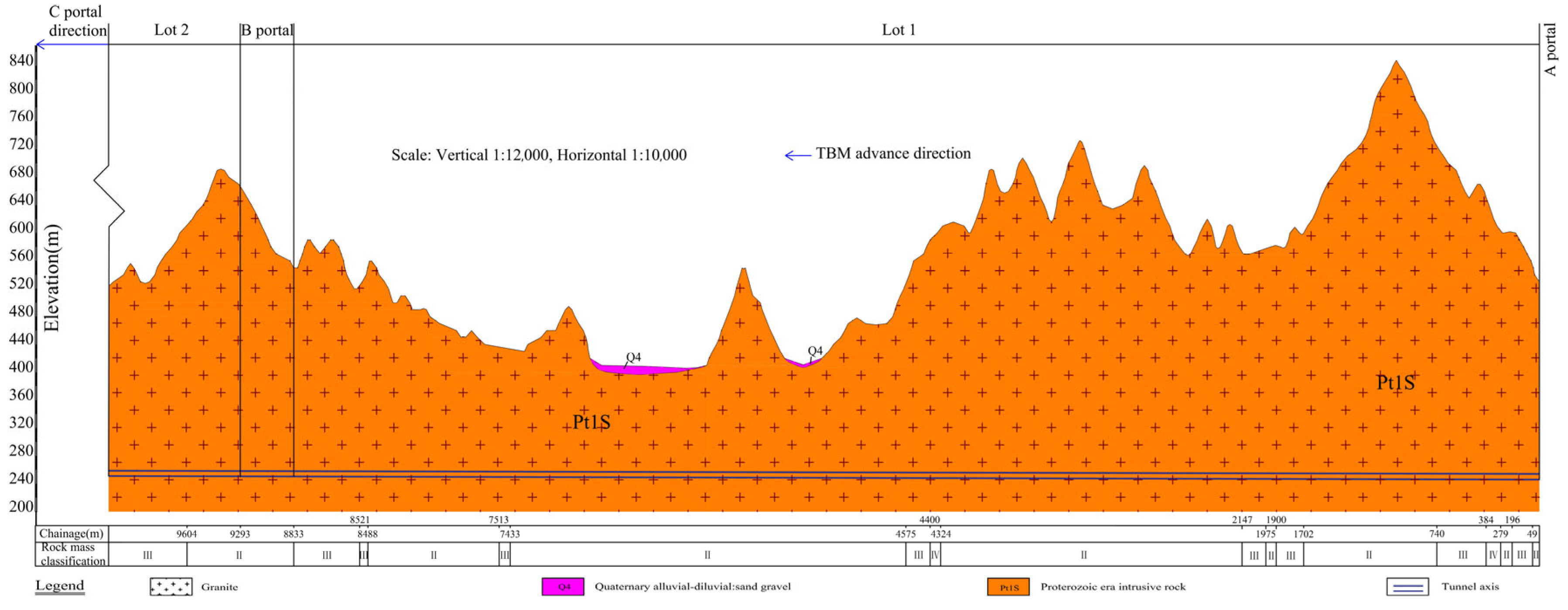
Figure 1. Longitudinal geological profile along the studied tunnel. Reprinted with permission from Ref. [2]. 2024, J. Liu.
Buildings 14 01523 g001
Figure 2. TBM cutter head diagram.
Buildings 14 01523 g002
Figure 3. TBM cutter layout diagram.
Buildings 14 01523 g003
Figure 4. Cutter wear: (a) cutter wear measurement with a gage and (b) normal wear of cutter ring.
Buildings 14 01523 g004
Figure 5. Statistical diagram of the accumulated radial wear extent and the replacement number of cutter rings in different cutter positions: (a) accumulated radial wear extent of cutter rings and (b) number of the replaced cutter rings.
Buildings 14 01523 g005
Figure 6. Relationships between cutter life evaluation indexes based on the radial wear extent of cutter rings and cutter installation radius: (a) Ki and Ri; (b) Vi and Ri; and (c) Li and Ri.
Buildings 14 01523 g006
Figure 7. Regression curves between the average radial wear extent of cutter rings per unit rolling distance and the cutter installation radius for different types of cutters: the (a) center cutter and (b) gage cutter.
Buildings 14 01523 g007
Figure 8. Regression curves between the average radial wear extent of cutter rings per unit rock-breaking volume and cutter installation radius for different types of cutters: the (a) center cutter and (b) gage cutter.
Buildings 14 01523 g008
Figure 9. Fitting curve between cutter spacing and the cutter position number for the gage cutter.
Buildings 14 01523 g009
Figure 10. Regression curves between the average radial wear extent of cutter rings per unit tunneling distance and the cutter installation radius for different types of cutters: the (a) center cutter; (b) face cutter, and (c) gage cutter.
Buildings 14 01523 g010
Figure 11. Relationship between cutter life evaluation indexes based on the replacement number of cutter rings and cutter installation radius: (a) Hm and Ri; (b) Hf and Ri; and (c) Hk and Ri.
Buildings 14 01523 g011
Figure 12. Regression curves between the average tunneling distance of a single cutter ring and the cutter installation radius for different types of cutters: the (a) center cutter and (b) face cutter.
Buildings 14 01523 g012
Figure 13. Regression curves between the average rock-breaking volume of a single cutter ring and cutter installation radius for different types of cutters: (a) center cutter; (b) face cutter; and (c) gage cutter.
Buildings 14 01523 g013
Figure 14. Fitting curves between the replacement number of cutter rings and the cutter installation radius for face cutters.
Buildings 14 01523 g014
Figure 15. Regression curves between the average rolling distance of a single cutter ring and the cutter installation radius for different types of cutters: the (a) center cutter and (b) face cutter.
Buildings 14 01523 g015
Table 1. Statistical table of the existing cutter life evaluation indexes.
No.Index TypeCutter Life Evaluation IndexSource
1Indexes based on mass loss of cutter ringsMass loss of cutter rings per unit rolling distance (mg/m)[23]
2Mass loss of cutter rings per unit rock-breaking volume (mg/m3)[24]
3Indexes based on radial wear extent of cutter ringsRock-breaking volume per unit radial wear extent of cutter rings (m3/mm)[2]
4Radial wear extent of cutter rings per unit rolling distance (mm/m)[25]
5Radial wear extent of cutter rings per unit tunneling distance (mm/m)[26]
6Indexes based on replacement number of cutter ringsTunneling distance of a single cutter ring (m/cutter)[27]
7Rolling distance of a single cutter ring (m/cutter)[28]
8Rock-breaking volume of a single cutter ring (m3/cutter)[29]
9Indexes based on energy analysisAccumulative value of disc cutter friction work (J)[30]
10Accumulated wear extent of cutter rings at a single cutter position (mm)[31]
11Other indexesMaximum tunneling distance of a cutter ring (m)[33]
12Cutter ring health index[34]
The reciprocal of some indexes can also be used as the cutter life evaluation index.
Table 2. Summary of regression relationships between the two kinds of cutter life evaluation indexes and installation radius.
Cutter Life Evaluation IndexType of Disc Cutter
Center CutterFace CutterGage Cutter
Ki
(mm/m)
Quadratic function
y = 4.24 × 10 5 x 2 + 2.86 × 10 5 x + 2.26 × 10 5 ( R 2 = 0.80 )
IrrelevantQuadratic function
y = 1.24 × 10 4 x 2 + 1.03 × 10 3 x 2.12 × 10 3 ( R 2 = 0.76 )
Vi
(mm/m3)
Exponential function
y = 0.39 × 7.20 × 10 6 x + 0.04 ( R 2 = 0.99 )
IrrelevantQuadratic function
y = 3.60 x 2 28.87 x + 57.94 ( R 2 = 0.92 )
Li
(mm/m)
Linear function (increases)
y = 1.22 × 10 2 x + 6.62 × 10 3 ( R 2 = 0.82 )
Linear function (increase)
y = 7.71 × 10 3 x + 7.87 × 10 3 ( R 2 = 0.90 )
Quadratic function
y = 0.44 x 2 + 3.66 x 7.58 ( R 2 = 0.82 )
Hm
(m/cutter)
/Linear function (decrease)
y = 188.01 x + 1083.01 ( R 2 = 0.80 )
Irrelevant
Hf
(m3/cutter)
Linear function (increases)
y = 362.65 x + 6.89 ( R 2 = 0.96 )
Quadratic function
y = 109.87 x 2 + 620.30 x 8.91 ( R 2 = 0.66 )
Linear function (decrease)
y = 1142.64 x + 4924.09 ( R 2 = 0.96 )
Hk
(m/cutter)
Linear function (increases)
y = 5.49 × 10 5 x + 7.20 × 10 3 ( R 2 = 0.95 )
Quadratic function
y = 1.57 × 10 5 x 2 + 9.15 × 10 5 x + 3.53 × 10 4 ( R 2 = 0.65 )
Irrelevant
‘Irrelevant’ means that the cutter installation radius has almost no effect on the index and ‘/’ means that there is no obvious rule between the cutter installation radius and the index.
Disclaimer/Publisher’s Note: The statements, opinions and data contained in all publications are solely those of the individual author(s) and contributor(s) and not of MDPI and/or the editor(s). MDPI and/or the editor(s) disclaim responsibility for any injury to people or property resulting from any ideas, methods, instructions or products referred to in the content.