
Analysis of Out-of-Plane Displacements of a Light Steel Keel Fireproof Exterior Wall and Its Connection with the Steel Frame


Abstract
1. Introduction
2. Materials and Methods
2.1. Finite Element Modeling and Validation
- (1)
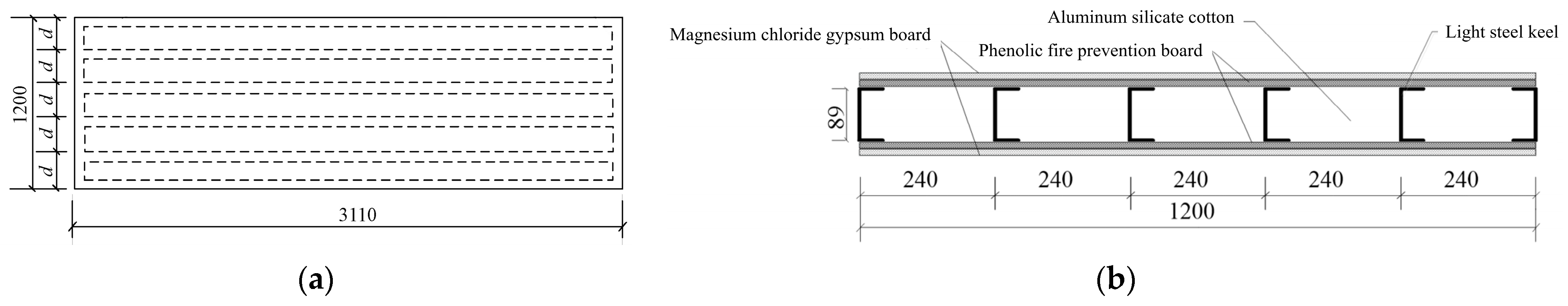
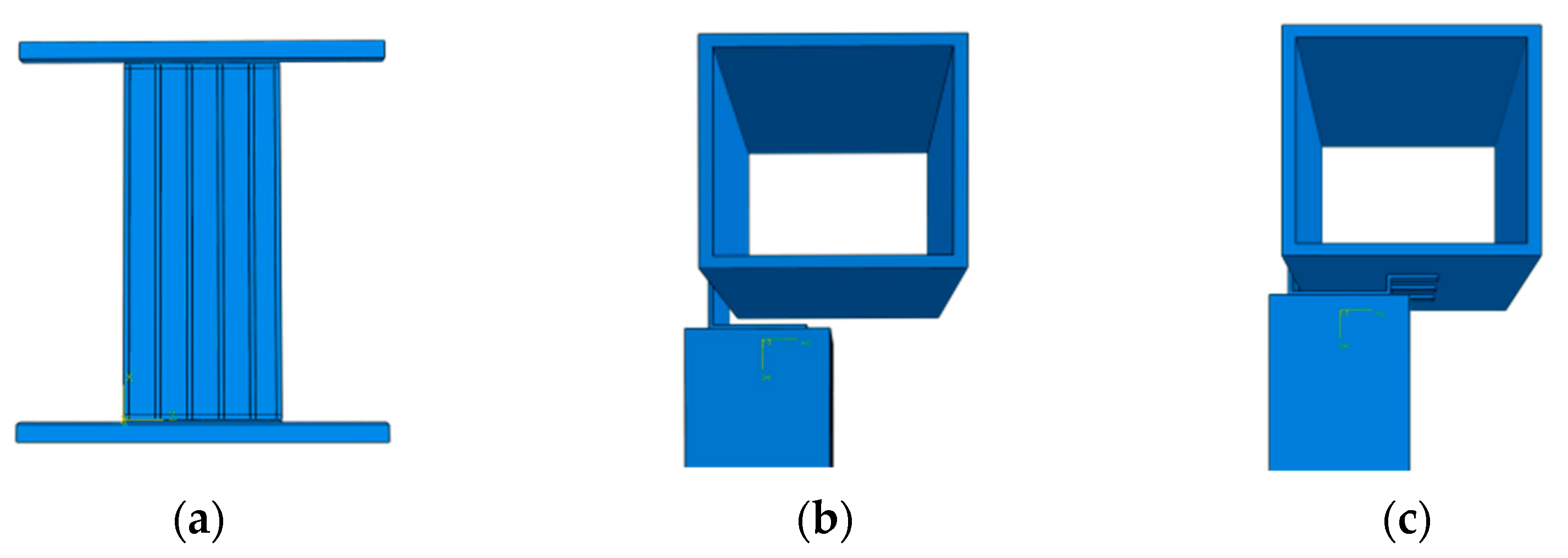
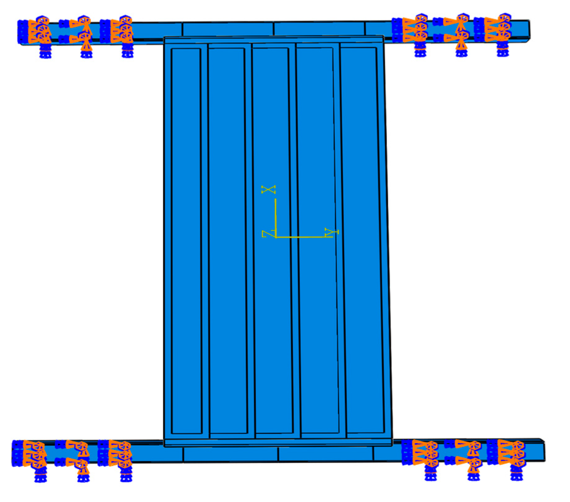
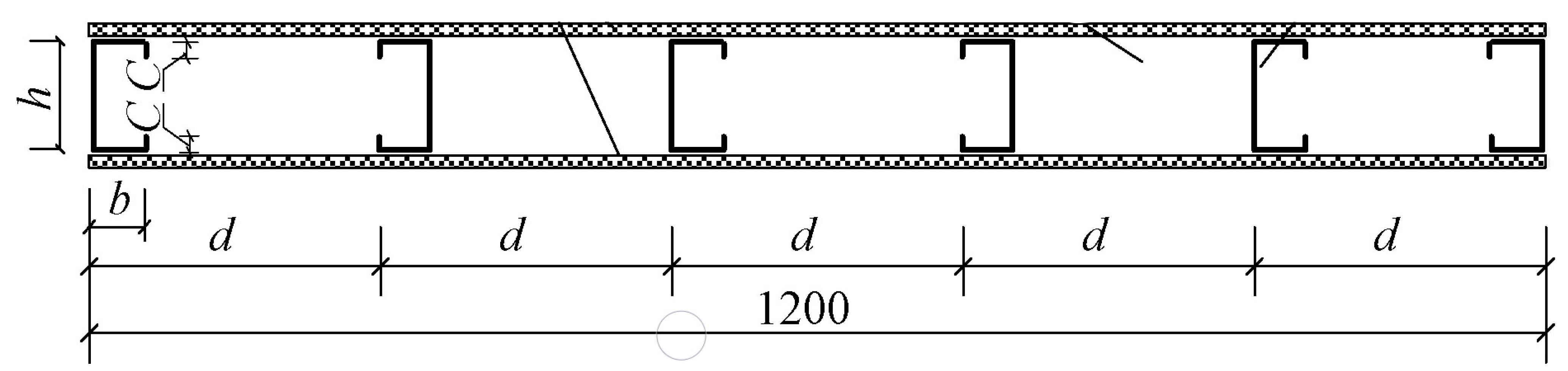
- Modelling of geometry
- (2)
- Material properties
- (3)
- Unit type and mesh size selection
- (4)
- Interactions and constraints
- (5)
- Loading procedure
- (6)
- Validation
2.2. Simulation Scheme
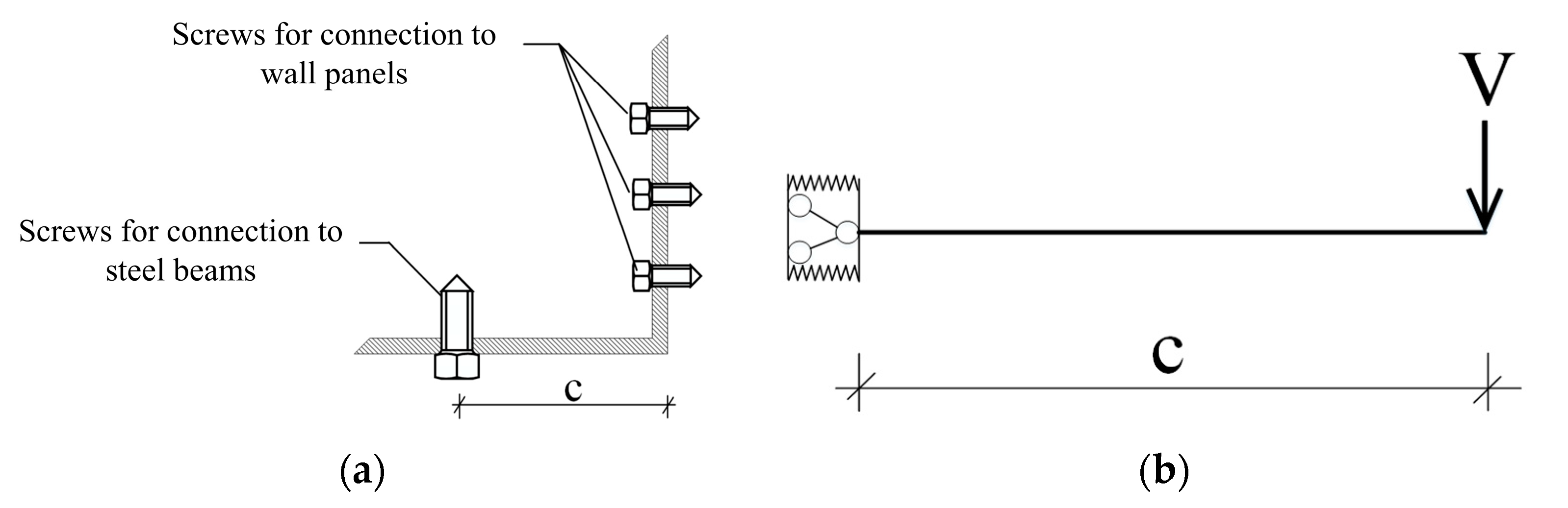
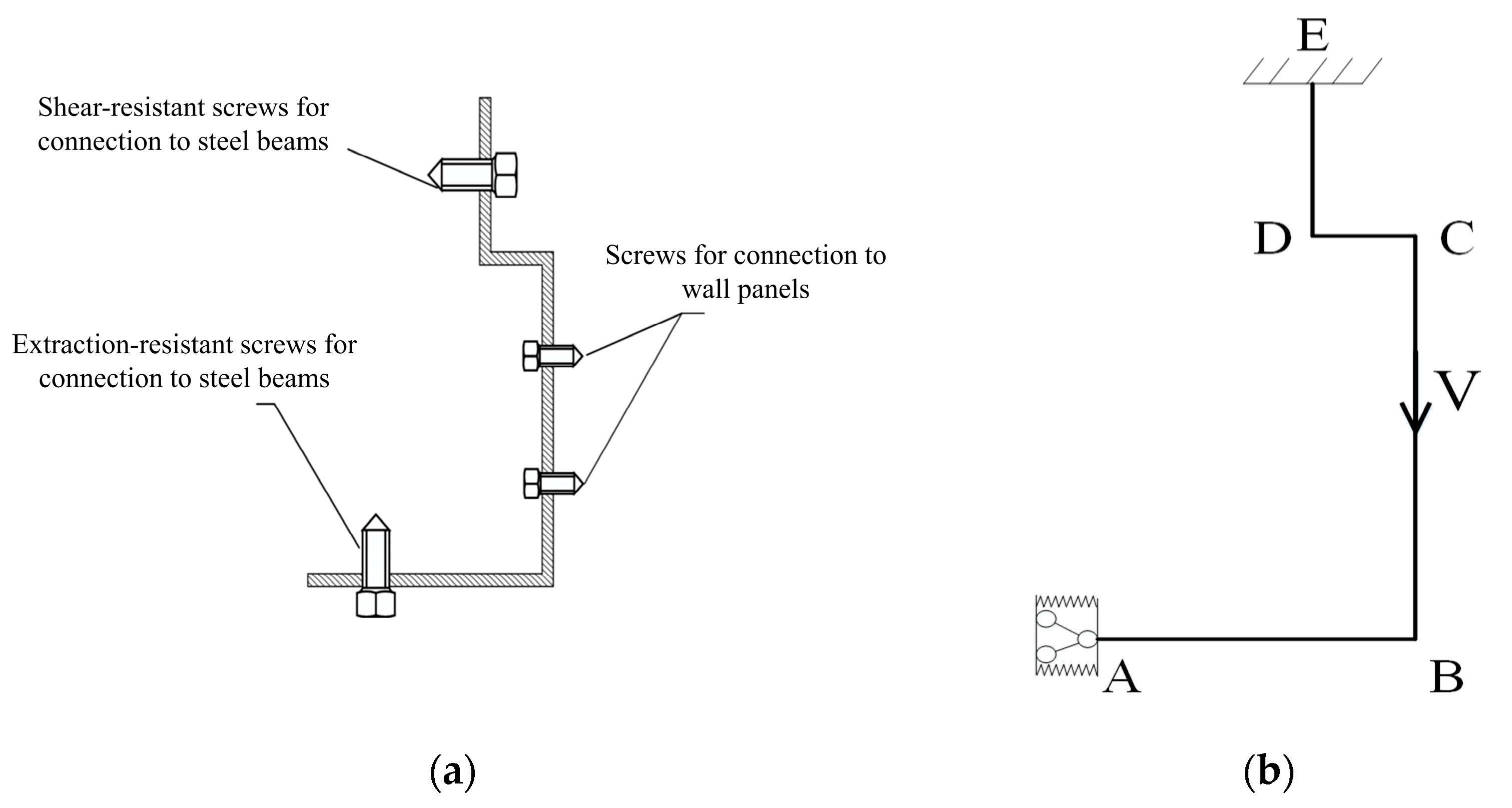
2.3. Displacement Calculation Model
- (1)
- Displacement calculation model for L-shaped steel angle connectors
- (2)
- Displacement calculation model for the special-shaped steel angle connectors
- (3)
- Displacement calculation model for the wall panel
3. Results
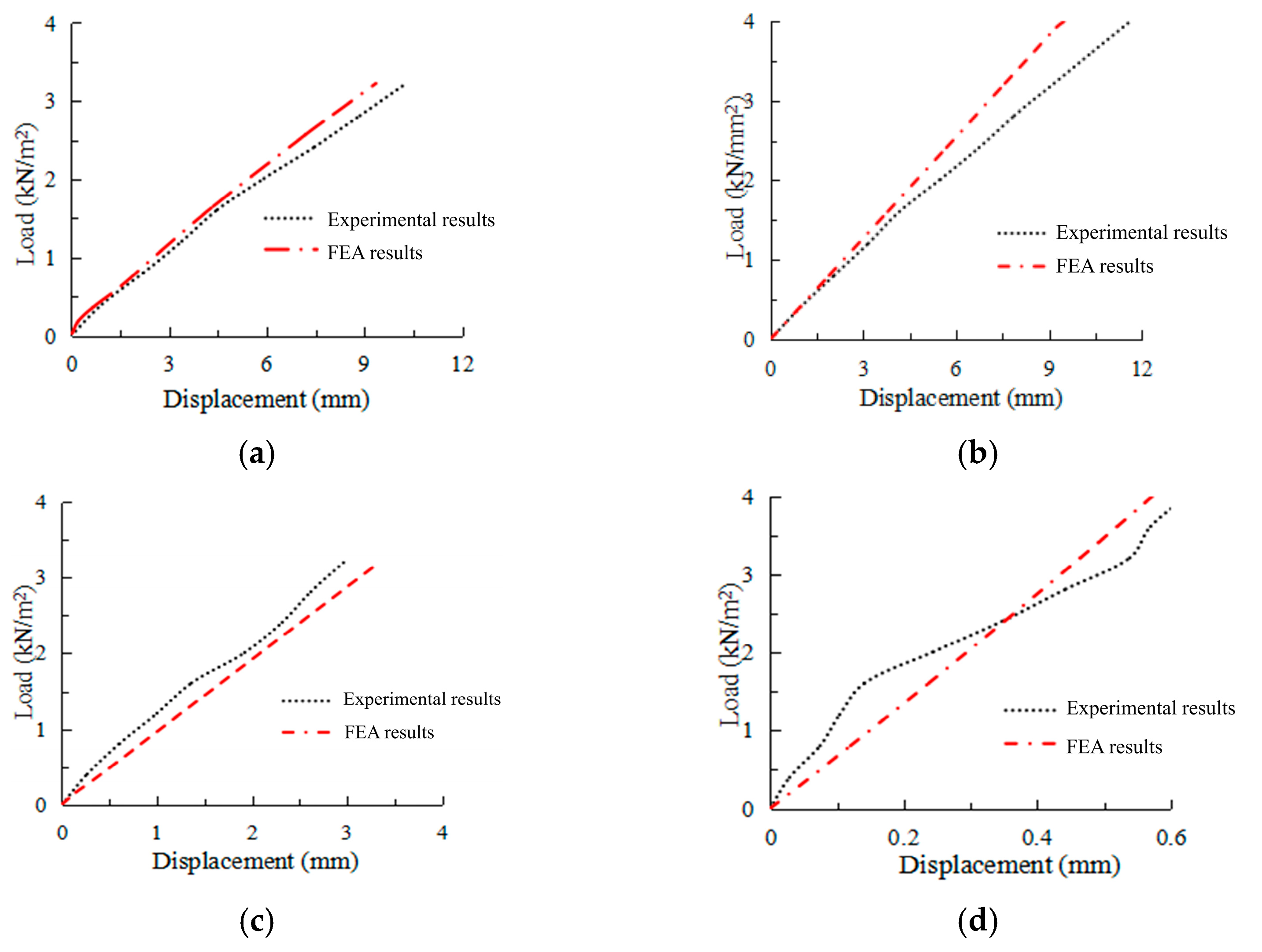
3.1. Comparison of Simulation and Experimental Results
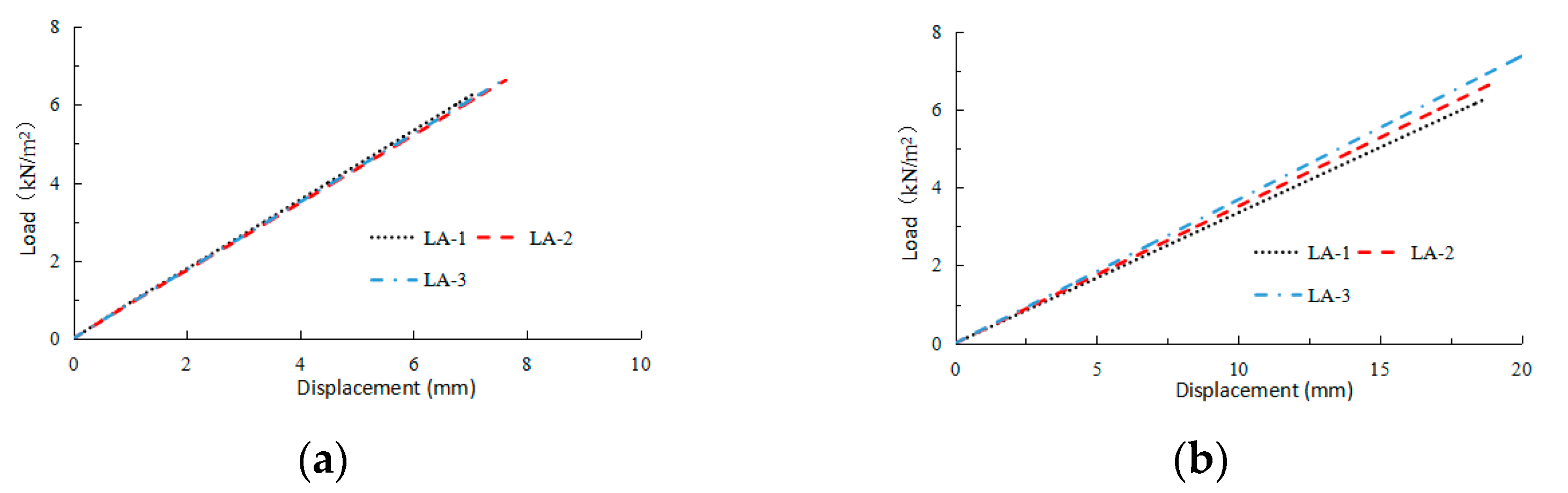
3.2. Analysis of Displacement Influencing Factors
3.2.1. L-Shaped Steel Angle Connectors and Wall Panels
- (1)
- Keel spacing
- (2)
- Thickness of the L-shaped steel angles
- (3)
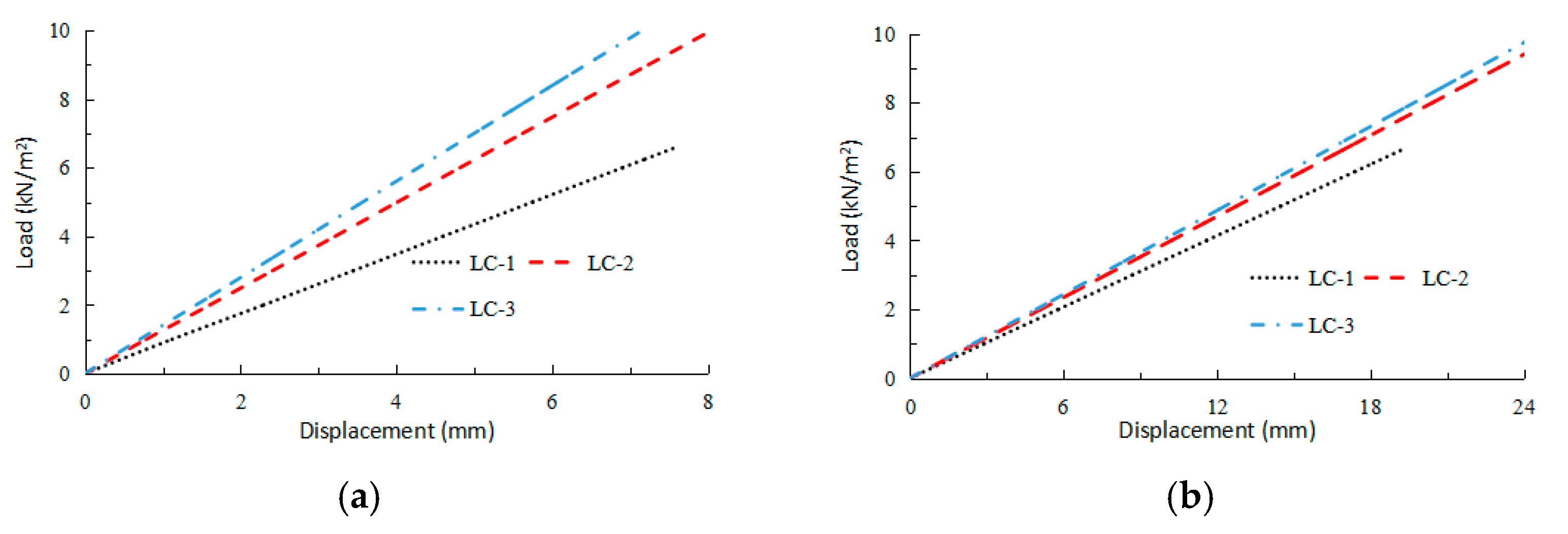
- Number of screws connecting the connector to the steel beams
- (4)
- Layout of the keel
3.2.2. Special-Shaped Connectors and Wall Panels
- (1)
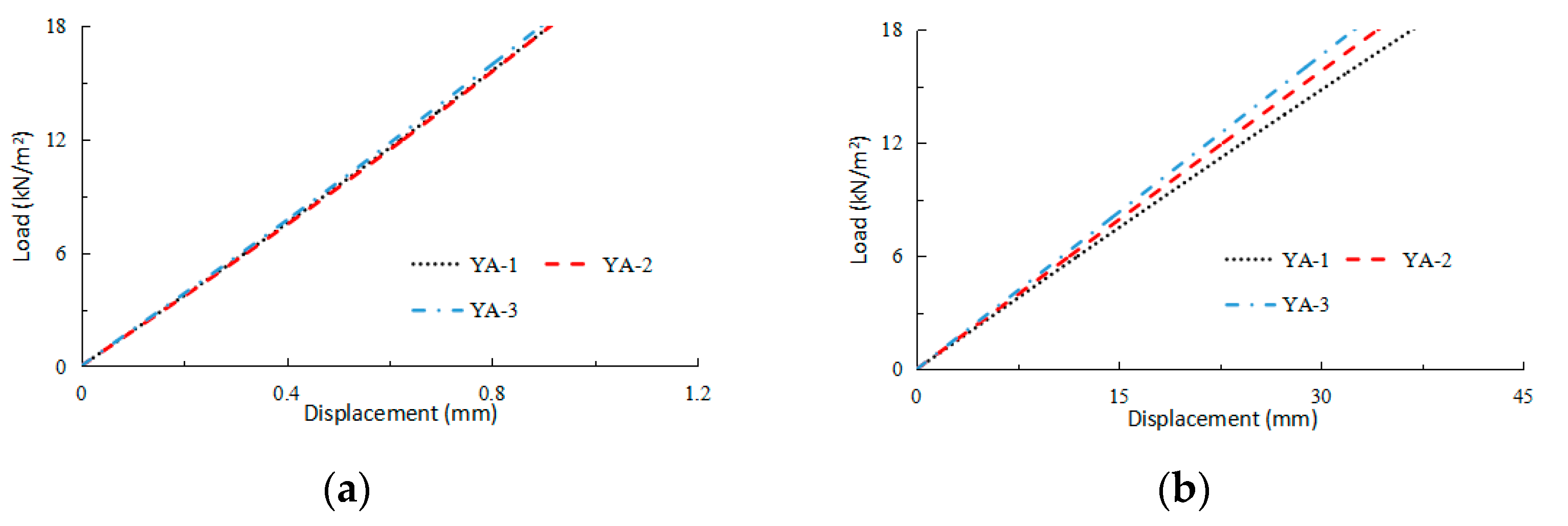
- Keel spacing
- (2)
- Number of special-shaped steel angle connectors
- (3)
- Layout of the keel
3.3. Displacement Model Modification
3.3.1. Displacement Model Modification for Connectors
3.3.2. Displacement Model Modification for Wall Panels
4. Discussion
4.1. Analysis of Factors Affecting the Displacements of Connectors and Wall Panels
4.2. Modification of the Displacement Model for Connectors and Wall Panels
4.3. Limitations
5. Conclusions
- (1)
- The reduction of the keel spacing could improve the out-of-plane stiffness of the wall panels but has little effect on the stiffness of the connectors.
- (2)
- The increase in the number of screws connecting the L-shaped steel angles to the steel beams can result in significant increases in the out-of-plane stiffnesses of the connectors and wall panels. When the number of screws reaches four or more, the stiffness enhancement effect of the connectors and wall panels will be weakened. In addition, increasing the thickness of the L-shaped steel angles can also improve the out-of-plane stiffnesses of the connectors and the wall panel, but the improvement effect is gradually insignificant when the thickness reaches a certain threshold.
- (3)
- The increase in the number of special-shaped steel angle connectors can result in significant increases in the out-of-plane stiffnesses of the connectors and wall panels. When the number of connectors reaches three or more, the stiffness enhancement effect of the connectors and wall panels will be weakened.
- (4)
- For the L-shaped steel angle connectors, the pre-proposed displacement model would overestimate the contribution of the number of screws to the rotational stiffness, making the calculation results smaller. The accuracy of the displacement model could be improved by modifying the rotation constraint coefficients of the L-shaped steel angle connectors.
- (5)
- For the wall panel, the ideal articulation constraints assumed by the pre-proposed displacement model would bias the calculations, and thus the introduction of the discount factor could improve the accuracy of the wallboard displacement model.
Author Contributions
Funding
Institutional Review Board Statement
Informed Consent Statement
Data Availability Statement
Acknowledgments
Conflicts of Interest
Notation
| BS | Combined stiffness of the wall panel |
| b | Wall plate section width |
| c | Distance from the center of the steel beam connecting screws to the line of shear effect |
| D0 | Lateral displacement stiffness |
| E | Modulus of elasticity of the connectors |
| ES | Modulus of elasticity of the light steel keel |
| I | Moment of inertia of the connectors |
| IS | Sum of the moments of inertia of the keel |
| I’1 | Moment of the inertia of the phenolic panels |
| Kb | Overall rotation constraint coefficient of the special-shaped steel angle connectors |
| ka | Rotation constraint coefficient of the L-shaped steel angle connector |
| kb | Rotation constraint coefficient of a single special-shaped steel angle connector |
| l0 | Calculated span of the wall panel |
| m | Mask combination effect coefficient |
| N | Number of special-shaped steel angle connectors |
| nt | Number of screws connecting L-shaped steel angle connectors to steel beams |
| n1 | Number of extraction-resistant screws |
| n2 | Number of shear-resistant screws |
| ta | Thickness of the L-shaped steel angle connector |
| tb | Thickness of the special-shaped steel angle connectors |
| wk | Load |
| γ | Discount factor |
| Δ | Displacement of the wall panel |
| Δa | Displacement of L-shaped steel angle connector |
| Δb | Displacement of special-shaped steel angle connectors |
References
- Yu, Y.Q.; Ma, X.F.; Zhang, A.L.; Wang, Z. Research summary on seismic performance of prefabricated steel plate shear wall structure. J. Build. Struct. 2021, 51, 16–24. [Google Scholar] [CrossRef]
- Xia, Z.; Zhu, L.M.; Han, L.Y.; Du, W.X. Classification and research status of exterior wall of prefabricated steel structure building. J. Henan Univ. 2021, 51, 728–738. [Google Scholar]
- Liang, X.J.; Wang, Y. State-of-the-art on semi-rigid connections for fabricated steel structures. Prog. Steel Build. Struct. 2022, 24, 1–14. [Google Scholar]
- Liu, H.B.; He, X.H.; Gao, L.; Li, F. Numerical simulation of the wind field of assembled steel truss bridge. Appl. Mech. Mater. 2013, 340, 841–847. [Google Scholar] [CrossRef]
- Roy, K.; Ananthi, G.B.G. Sustainable Composite Construction Materials; MDPI: Bern, Switzerland, 2023. [Google Scholar] [CrossRef]
- Kanagaraj, B.; Nammalvar, A.; Andrushia, A.D.; Gurupatham, B.G.A.; Roy, K. Influence of nano composites on the impact resistance of concrete at elevated temperatures. Fire 2023, 6, 135. [Google Scholar] [CrossRef]
- Ye, J.H. An introduction of mid-rise thin-walled steel structures: Research progress on cold-formed steel framed composite shear wall systems. J. Harbin Inst. Technol. 2016, 48, 1–9. [Google Scholar] [CrossRef]
- Paul Thanaraj, D.; Kiran, T.; Kanagaraj, B.; Nammalvar, A.; Andrushia, A.D.; Gurupatham, B.G.A.; Roy, K. Influence of heating-cooling regime on the engineering properties of structural concrete subjected to elevated temperature. Buildings 2023, 13, 295. [Google Scholar] [CrossRef]
- Zhang, A.L.; Hu, T.T.; Liu, X.C. The classification and comparative analysis of the matching external wall for the prefabricated steel structure residence. Ind. Constr. 2014, 44, 7–9. [Google Scholar] [CrossRef]
- Zhao, B. Crack causes analysis of filler wall of some steel structure masonry. Constr. Technol. 2009, S1, 397–398. [Google Scholar]
- Mehrabi, A.B.; Shing, P.B.; Schuller, M.P.; Noland, J.L. Experimental evaluation of masonry-infilled RC frames. J. Struct. Eng. 1996, 122, 228–237. [Google Scholar] [CrossRef]
- Naserpour, A.; Ghanbari, M.A.; Haseli, B. Seismic performance of precast concrete walls with replaceable steel slit connections for high-rise buildings. Innov. Infrastruct. Solut. 2024, 9, 47. [Google Scholar] [CrossRef]
- Zhao, Y.; Li, Z.; Liu, P.; Ma, H. The seismic behaviors of steel-concrete-steel composite walls with dumbbell-shaped connectors. J. Constr. Steel. Res. 2023, 211, 108182. [Google Scholar] [CrossRef]
- Lu, Y.L.; Jiang, L.Y.; Lin, F. Seismic performance of precast concrete shear wall using grouted sleeve connections for section steels reinforced at wall ends. Structures 2023, 57, 105068. [Google Scholar] [CrossRef]
- Geng, Y.; Wang, Y.Y.; Ding, J.Z. Mechanical behavior of connections between out-hung light-gauge steel stud walls and steel frames. J. Build. Struct. 2016, 37, 141–150. [Google Scholar] [CrossRef]
- Tang, Z.; Zha, X.; Wang, B. Finite element study on shear performances of in-filled bolt joint of assembled GRC wall with light steel skeleton frame. IOP Conf. Ser. Earth. Env. Sci. 2019, 267, 042094. [Google Scholar] [CrossRef]
- Heimbs, S.; Pein, M. Failure behaviour of honeycomb sandwich corner joints and inserts. Compos. Struct. 2009, 89, 575–588. [Google Scholar] [CrossRef]
- Tian, Y.; Guan, H.; Shao, S.; Yang, Q. Provisions and comparison of Chinese wind load standard for roof components and cladding. Structures 2021, 33, 2587–2598. [Google Scholar] [CrossRef]
- Bui, T.L.; Bui, T.T.; Bui, Q.B.; Limam, A. Out-of-plane behavior of rammed earth walls under seismic loading: Finite element simulation. Structures 2020, 24, 191–208. [Google Scholar] [CrossRef]
- Zhang, Y.; Liu, P.; Zhao, X.F. Structural displacement monitoring based on mask regions with convolutional neural network. Constr Build Mater. 2021, 267, 120923. [Google Scholar] [CrossRef]
- Chai, H.Y.; Ba, P.F.; Qiao, W.T.; Wang, Q. Analysis and experimental study of vertical ultimate load bearing capacity of light steel dense-ribbed walls. New Build. Mater. 2024, 51, 14–20. [Google Scholar]
- Xu, Q.; Lu, W.H.; Wang, M.; Meng, Z.B. Experimental study on effect of initial deformation on shear capacity of W-shaped light steel floor. Build. Sci. 2023, 39, 127–135. [Google Scholar]
- Bian, J.L.; Cao, W.L.; Wu, Z.Y. Experimental study on the seismic performance of composite wall of light steel and tailings microcrystal foamed plate. World. Earthq. Eng. 2023, 39, 75–87. [Google Scholar] [CrossRef]
- Zhao, S.X.; Fan, Q.C.; Zhang, Z.Q.; Peng, M.; Li, Y. Study on bond-slip behavior in lightweight steel and lightweight concrete composite column. Build. Sci. 2022, 38, 151–157+182. [Google Scholar]
- Wu, F.W.; Li, Y.Q. Numerical simulation on shear performance and conversion method considering height to width ratio effect of cold-formed steel framing walls using OpenSees. J. Build. Struct. 2023, 44, 225–235. [Google Scholar] [CrossRef]
- Nassiraei, H.; Rezadoost, P. Initial stiffness, ultimate capacity and failure mechanisms of tubular X-joints with external ring or plates at fire conditions. Ships. Offshore Struc. 2024, 236, 2317656. [Google Scholar] [CrossRef]
- Telue, Y.; Mahendran, M. Behavior of cold-formed steel wall frames lined with plasterboard. J. Constr. Steel. Res. 2001, 54, 435–452. [Google Scholar] [CrossRef]
- Tian, Y.S.; Wang, J.; Lu, T.J. Racking strength and Stiffness of Cold-formed Steel Wall Frames. J. Constr. Steel. Res. 2004, 60, 1069–1093. [Google Scholar] [CrossRef]
- Chou, S.M.; Chai, G.B.; Ling, L. Finite element technique for design of stub columns. Thin Wall Struct. 2000, 37, 97–112. [Google Scholar] [CrossRef]
- Wang, J.C.; Qiu, Z.M.; Liang, J.H. Experimental investigations on the lateral performance of foam concrete light steel keel composite wall. J. Build. Eng. 2023, 72, 106551. [Google Scholar] [CrossRef]
- Peng, H.J.; Luo, D.; Deng, X. Study on integral assembled light steel keel external wall panel. Guangdong Archit. Civ. Eng. 2019, 26, 92–95. [Google Scholar]
- Zou, X.Y.; Li, K. Research on lateral performance of the connection between light steel keel fireproof exterior wall and steel frame. J. Build. Struct. 2023, 53, 146–152. [Google Scholar] [CrossRef]
- Li, K.; Wang, L.; Tang, W.L.; Wang, X.L. Analysis on out-of-plane mechanical behaviors of lightweight steel keel fireproof exterior wall and its connection with steel frame. J. Build. Struct. 2023, 53, 127–135. [Google Scholar] [CrossRef]
- Zhang, H.X.; Li, G.C.; Yang, P. FEM analysis on out-of-plane mechanical performance of light steel interior wall with new type connection. Steel. Constr. 2016, 31, 53–58. [Google Scholar] [CrossRef]
- Bao, W.; Guo, R.; Yuan, S. Lateral force resistance behavior of semi-rigid steel frame with light steel keel wall. J. Build. Struct. 2013, 34, 154–160. [Google Scholar]
- Balik, F.S.; Bahadir, F.; Kamanli, M. Seismic Behavior of lap splice reinforced concrete frames with light-steel-framed walls and different anchorage details. Struct. Eng. Int. 2023, 33, 488–497. [Google Scholar] [CrossRef]


| Materials | Modulus of Elasticity (MPa) | Yield Strength (MPa) | Poisson’s Ratio |
|---|---|---|---|
| Cold-formed thin-walled steel | 171,000 | 293.7 | 0.31 |
| Q235 ordinary carbon steel | 210,000 | 235 | 0.30 |
| Q345 ordinary carbon steel | 210,000 | 345 | 0.3 |
| Materials | True Stress (MPa) | True Plastic Strain |
|---|---|---|
| Cold-formed thin-walled steel | 294.19 | 0 |
| 300.76 | 0.0146230 | |
| 338.43 | 0.0542114 | |
| 371.56 | 0.0836651 | |
| 436.39 | 0.1885053 | |
| Q235 ordinary carbon steel | 235.2628 | 0 |
| 431.876 | 0.075555 | |
| Q345 ordinary carbon steel | 345.5663 | 0 |
| 537.7247 | 0.071099 |
| Materials | Modulus of Elasticity (MPa) | Strength (MPa) | Poisson’s Ratio |
|---|---|---|---|
| Phenolic fire-prevention board | 34,500 | 391.2 | 0.29 |
| Magnesium chloride gypsum board | 1500 | 1.13 | 0.38 |
| Number | Connector Thickness (mm) | Steel Angle Type | Keel Layout | Keel Spacing (mm) | Number of Self-Tapping Screws for Connectors to Steel Beams | Number of Self-Tapping Screws for Connectors to Wall Panels |
|---|---|---|---|---|---|---|
| LA-1 | 2.5 | L-shaped | Normal | 300 | 3 unilateral | 8 unilateral |
| LA-2 | 2.5 | L-shaped | Normal | 240 | 3 unilateral | 8 unilateral |
| LA-3 | 2.5 | L-shaped | Normal | 200 | 3 unilateral | 8 unilateral |
| LB-1 | 1.5 | L-shaped | Asymmetrical | 240 | 3 unilateral | 8 unilateral |
| LB-2 | 2 | L-shaped | Asymmetrical | 240 | 3 unilateral | 8 unilateral |
| LB-3 | 2.5 | L-shaped | Asymmetrical | 240 | 3 unilateral | 8 unilateral |
| LC-1 | 2.5 | L-shaped | Asymmetrical | 240 | 3 unilateral | 8 unilateral |
| LC-2 | 2.5 | L-shaped | Asymmetrical | 240 | 4 unilateral | 8 unilateral |
| LC-3 | 2.5 | L-shaped | Asymmetrical | 240 | 5 unilateral | 8 unilateral |
| YA-1 | 2.5 | Special-shaped (3 unilateral) | Normal | 300 | 12 unilateral | 12 unilateral |
| YA-2 | 2.5 | Special-shaped (3 unilateral) | Normal | 240 | 12 unilateral | 12 unilateral |
| YA-3 | 2.5 | Special-shaped (3 unilateral) | Normal | 200 | 12 unilateral | 12 unilateral |
| YB-1 | 2.5 | Special-shaped (2 unilateral) | Asymmetrical | 240 | 8 unilateral | 8 unilateral |
| YB-2 | 2.5 | Special-shaped (3 unilateral) | Asymmetrical | 240 | 12 unilateral | 12 unilateral |
| YB-3 | 2.5 | Special-shaped (4 unilateral) | Asymmetrical | 240 | 16 unilateral | 16 unilateral |
| Components | FEA Values (F) | Experimental Values (E) | F/E |
|---|---|---|---|
| Connectors for QB1 | 3.16 | 2.97 | 1.06 |
| Connectors for QB2 | 0.57 | 0.63 | 0.90 |
| Wall panel for QB1 | 9.42 | 10.25 | 0.92 |
| Wall panel for QB2 | 9.56 | 11.7 | 0.82 |
| Number | Kb (kα) | Extreme Load (kN/m2) | Simulated Displacement (S) (mm) | Theoretically Calculated Displacement (T) (mm) | S/T |
|---|---|---|---|---|---|
| LA-1 | 0.181 | 5.5 | 5.51 | 5.35 | 1.029 |
| LA-2 | 0.181 | 5.7 | 5.71 | 5.55 | 1.029 |
| LA-3 | 0.181 | 6.5 | 6.12 | 6.33 | 0.967 |
| LB-1 | 0.541 | 5.4 | 8.91 | 8.14 | 1.095 |
| LB-2 | 0.316 | 5.5 | 6.61 | 5.99 | 1.104 |
| LB-3 | 0.181 | 5.8 | 5.81 | 5.64 | 1.029 |
| LC-1 | 0.181 | 5.8 | 5.81 | 5.64 | 1.029 |
| LC-2 | 0.361 | 7.5 | 5.70 | 3.67 | 1.555 |
| LC-3 | 0.541 | 9.2 | 5.75 | 2.98 | 1.928 |
| YA-1 | 0.348 | 9.7 | 0.58 | 0.65 | 0.899 |
| YA-2 | 0.348 | 12.1 | 0.73 | 0.80 | 0.909 |
| YA-3 | 0.348 | 10.4 | 0.60 | 0.69 | 0.871 |
| YB-1 | 0.185 | 5.1 | 0.74 | 0.89 | 0.832 |
| YB-2 | 0.348 | 12.5 | 0.76 | 0.83 | 0.917 |
| YB-3 | 0.510 | 14.7 | 0.66 | 0.67 | 0.998 |
| Number | kα | Simulated Displacement (S) (mm) | Theoretically Calculated Displacement (T) (mm) | S/T |
|---|---|---|---|---|
| LA-1 | 0.181 | 5.353 | 5.51 | 1.029 |
| LA-2 | 0.181 | 5.548 | 5.71 | 1.029 |
| LA-3 | 0.181 | 6.326 | 6.12 | 0.967 |
| LB-1 | 0.542 | 8.122 | 8.91 | 1.097 |
| LB-2 | 0.317 | 5.968 | 6.61 | 1.108 |
| LB-3 | 0.181 | 5.643 | 5.81 | 1.029 |
| LC-1 | 0.181 | 5.643 | 5.81 | 1.029 |
| LC-2 | 0.231 | 5.732 | 5.7 | 0.994 |
| LC-3 | 0.281 | 5.743 | 5.75 | 1.001 |
| Number | Combined Stiffness (kN·m2) | Extreme Load (kN/m2) | Simulated Displacement (S) (mm) | Theoretically Calculated Displacement (T) (mm) | S/T |
|---|---|---|---|---|---|
| LA-1 | 617.21 | 5.50 | 10.24 | 13.03 | 0.786 |
| LA-2 | 568.08 | 5.70 | 9.96 | 14.67 | 0.679 |
| LA-3 | 617.21 | 6.50 | 10.85 | 15.39 | 0.705 |
| LB-1 | 568.08 | 5.40 | 9.36 | 13.89 | 0.674 |
| LB-2 | 568.08 | 5.50 | 9.57 | 14.15 | 0.676 |
| LB-3 | 568.08 | 5.80 | 10.13 | 14.92 | 0.679 |
| LC-1 | 568.08 | 5.80 | 10.13 | 14.92 | 0.679 |
| LC-2 | 568.08 | 7.52 | 13.10 | 19.34 | 0.677 |
| LC-3 | 568.08 | 9.16 | 15.98 | 23.57 | 0.678 |
| YA-1 | 514.66 | 9.73 | 18.94 | 27.63 | 0.685 |
| YA-2 | 568.08 | 12.10 | 22.21 | 31.13 | 0.713 |
| YA-3 | 617.21 | 10.40 | 18.37 | 24.63 | 0.746 |
| YB-1 | 568.08 | 5.11 | 10.80 | 13.15 | 0.821 |
| YB-2 | 568.08 | 12.50 | 22.91 | 32.16 | 0.712 |
| YB-3 | 568.08 | 14.70 | 26.69 | 37.82 | 0.706 |
| Number | Combined Stiffness (kN·m2) | Extreme Load (kN/m2) | Simulated Displacement (S) (mm) | Theoretically Calculated Displacement (T) (mm) | S/T |
|---|---|---|---|---|---|
| LA-1 | 617.21 | 5.50 | 10.24 | 11.09 | 0.923 |
| LA-2 | 568.08 | 5.70 | 9.96 | 10.41 | 0.957 |
| LA-3 | 617.21 | 6.50 | 10.85 | 10.93 | 0.993 |
| LB-1 | 568.08 | 5.40 | 9.36 | 9.87 | 0.948 |
| LB-2 | 568.08 | 5.50 | 9.57 | 10.05 | 0.952 |
| LB-3 | 568.08 | 5.80 | 10.13 | 10.60 | 0.956 |
| LC-1 | 568.08 | 5.80 | 10.13 | 10.60 | 0.956 |
| LC-2 | 568.08 | 7.52 | 13.10 | 13.73 | 0.954 |
| LC-3 | 568.08 | 9.16 | 15.98 | 16.73 | 0.955 |
| YA-1 | 514.66 | 9.73 | 18.94 | 19.62 | 0.965 |
| YA-2 | 568.08 | 12.10 | 22.21 | 22.11 | 1.005 |
| YA-3 | 617.21 | 10.40 | 18.37 | 17.49 | 1.050 |
| YB-1 | 568.08 | 5.109 | 10.80 | 9.33 | 1.158 |
| YB-2 | 568.08 | 12.50 | 22.91 | 22.84 | 1.003 |
| YB-3 | 568.08 | 14.70 | 26.69 | 26.86 | 0.994 |
Disclaimer/Publisher’s Note: The statements, opinions and data contained in all publications are solely those of the individual author(s) and contributor(s) and not of MDPI and/or the editor(s). MDPI and/or the editor(s) disclaim responsibility for any injury to people or property resulting from any ideas, methods, instructions or products referred to in the content. |
© 2024 by the authors. Licensee MDPI, Basel, Switzerland. This article is an open access article distributed under the terms and conditions of the Creative Commons Attribution (CC BY) license (https://creativecommons.org/licenses/by/4.0/).
Share and Cite
Wang, A.; Gao, R.; Li, H.; Li, J.; Li, K. Analysis of Out-of-Plane Displacements of a Light Steel Keel Fireproof Exterior Wall and Its Connection with the Steel Frame. Buildings 2024, 14, 1564. https://doi.org/10.3390/buildings14061564
Wang A, Gao R, Li H, Li J, Li K. Analysis of Out-of-Plane Displacements of a Light Steel Keel Fireproof Exterior Wall and Its Connection with the Steel Frame. Buildings. 2024; 14(6):1564. https://doi.org/10.3390/buildings14061564
Chicago/Turabian StyleWang, Ang, Ruiyuan Gao, Hao Li, Jing Li, and Ke Li. 2024. "Analysis of Out-of-Plane Displacements of a Light Steel Keel Fireproof Exterior Wall and Its Connection with the Steel Frame" Buildings 14, no. 6: 1564. https://doi.org/10.3390/buildings14061564
APA StyleWang, A., Gao, R., Li, H., Li, J., & Li, K. (2024). Analysis of Out-of-Plane Displacements of a Light Steel Keel Fireproof Exterior Wall and Its Connection with the Steel Frame. Buildings, 14(6), 1564. https://doi.org/10.3390/buildings14061564