Article

Seismic Performance of Precast Double-Skin Composite Shear Wall with Horizontal Connection Region

College of Architecture Engineering, North China Institute of Aerospace Engineering, Langfang 065000, China
*
Author to whom correspondence should be addressed.
Buildings 2024, 14(6), 1617; https://doi.org/10.3390/buildings14061617
Submission received: 6 May 2024 / Revised: 26 May 2024 / Accepted: 29 May 2024 / Published: 1 June 2024
(This article belongs to the Special Issue Advances in Steel–Concrete Composite Structures)

Abstract

:
This paper proposed a novel, precast double-skin composite (DSC) shear wall, which was composed of two precast parts at the factory and welding and pouring grouting material on site. One monolithic cast-in-place DSC shear wall specimen and two precast DSC shear wall specimens with different axial compression ratios were subjected to reverse cyclic loading tests. The results indicated that the failure mode of both the cast-in-place and precast DSC shear wall shear walls were compression-bending failures, and the damage range of specimens within a height range of 100 mm to 200 mm from the bottom of the DSC shear wall. The load-bearing capacity of the precast specimen was 6.3% higher than that of the monolithic counterpart, but its ductility was reduced by 16%. The precast DSC shear wall with better casting quality and easier site installation exhibited a satisfactory seismic performance on a par with that of the monolithic cast-in-place DSC shear wall. Under higher axial compression ratios, the bearing capacity and energy dissipation of the precast DSC shear wall specimen significantly improved due to the enhanced confinement effect. Finite element (FE) models clarified the stress and deformation mechanisms between the exterior steel plate and the infill concrete. Finally, the key parameters affecting the seismic bearing capacity of the precast DSC shear wall were identified through FE parameter analysis.

1. Introduction

Shear walls as lateral load-resisting elements have been widely employed in high-rise buildings for decades to withstand the lateral loads induced by earthquakes and wind as well as vertical load induced by gravity [1]. Precast reinforced concrete (RC) shear walls with grouted sleeve connections are predominant in Chinese high-rise prefabricated structural systems [2,3]. As the height of high-rise buildings has increased, the demand for larger cross-sections of RC shear wall has grown due to the amplified base shear, bending moments, and self-weight. The axial compression ratio, as a vital parameter affecting the seismic behavior precast RC shear walls with grouted sleeve connections, must meet the limit value specified in seismic design standards like GB 50011-2010 [4], ACI 318 [5], and Eurocode8 [6] for ensuring sufficient ductility and deformation capacity under seismic action. The increased cross-section of RC shear walls reduces the rentable building space and increases the gravity of buildings that then intensifies the seismic horizontal base shear force [7]. Additionally, precast RC shear walls require grouted sleeve connections with relatively high installation accuracy and highly skilled labor due to their vulnerability to construction errors and uncertainties. Thus, using RC shear walls with grouted sleeve connections in ultra-high buildings is often impractical and uneconomical.
A double-skin composite (DSC) shear wall is an innovative lateral load-resisting system, comprising exterior steel plates, infill concrete, boundary columns, and connectors. On the one hand, the concrete under triaxial compression demonstrates superior strength and ductility due to the confinement effect from the exterior steel plates. The exterior steel plates function as the confinement for the infill concrete and the formwork for casting in situ concrete. On the other hand, the infill concrete can prevent premature local buckling of exterior steel plates. Researchers including Ji et al. [8], Nie et al. [9], Hu et al. [10], Nie et al. [11], Chen et al. [12], Luo et al. [13], Zhang et al. [14], Zhang et al. [15], Ji et al. [16], Guo et al. [17], Huang et al. [18], and Yan et al. [19], have experimentally studied the behavior of DSC shear walls under combined axial loads and reversed cyclic loading. The results reveal that the strength and deformation of DSC shear walls are markedly better than those of RC shear walls even with high axial loads. Thus, the DSC shear walls are a viable substitute for conventional RC shear walls in ultra-high-rise buildings, offering smaller cross-sections, lighter weight, and more rentable building space. DSC shear walls have been utilized in high-rise and super-high-rise buildings like the Yancheng TV Tower, Beijing Fortune Plaza [20], China Zun Tower [21], and Beijing’s World Trade Center [22] in China. In practical engineering applications, DSC shear walls typically incorporate boundary columns and connectors. Nie et al. [9], Ji et al. [16,23], and Varma et al. [24] reported on the in-plane seismic response of the proposed DSC shear wall with boundary columns. Furthermore, connectors are also commonly applied to further increase the bonding performance between exterior steel plates and infill concrete. Researchers analyzed the seismic performance of DSC shear walls with different connectors, such as stud connectors, angle connectors, overlapped studs, J-hooks [25], L-connectors [26], tie bars [12,27], tie bolts [28,29], and batten plates [9]. It is worth noting that the head stud connectors in the DSC shear wall can effectively anchor exterior steel plates onto the infill concrete, and tie bolts counteract local buckling of steel plates.
Steel components or precast concrete elements can be prefabricated in factories and directly assembled on site. However, traditional DSC shear walls require welding of steel plates and concrete pouring on-site. Despite eliminating the need for formwork, the construction efficiency of traditional DSC shear walls is still hindered by the in situ concrete pouring process, which prevents synchronization with prefabricated construction. Moreover, on-site concrete pouring has resulted in an intricate construction process and extensive wet work that contribute to environmental pollution. Since the 1990s, scholars have extensively studied precast PC shear walls with a horizontal connection region. Hutchinson [30] proposed the construction form of assembling prefabricated walls with post-tensioned tendons. Soudki [31,32] studied the seismic performance and deformation capacity of precast PC shear walls with various connection regions and proposed design methods in horizontal connection regions in earthquake conditions. Qian [33] utilized sleeve grouting and hole grouting lap-splice methods for connecting vertical reinforcement in the horizontal connection region of precast components. The experiments revealed that the energy dissipation and stiffness of precast PC shear walls matched that of cast-in-place PC shear walls under low reversed cyclic loading. Sun [34] proposed a precast PC shear wall with dry connections, using high-strength bolts to connect the horizontal connection region. Current studies have mainly focused on precast PC shear walls with horizontal connection regions, with fewer studies examining precast DSC shear walls with horizontal connection regions.
This study introduces a precast DSC shear wall, as shown in Figure 1. The precast DSC shear wall is divided into upper and lower sections with boundary columns, featuring precast DSC wall components with factory-cast concrete and a horizontal connection region for site connection. Connection plates are placed within the horizontal connection region for accurate on-site alignment to promote precise alignment. The precast wall components consist of exterior steel plates, infilled concrete, and connectors. During construction, cranes lift the upper precast wall components to align with the lower ones. The upper and lower parts with boundary columns are joined by welding. Subsequently, high-strength grouting material is injected into the horizontal connection region through injected holes to integrate with the internal precast concrete. The innovative precast DSC shear wall using minimal welding and post-grouting technology enhances construction efficiency. Factory casting ensures the component quality, reduces environmental pollution, and minimizes material waste. It is noteworthy that the performance of prefabricated DSC shear walls largely depends on the quality of the grouting material after pouring. Any issues during the grouting process, such as incomplete filling or poor bonding, can significantly compromise structural integrity and seismic performance.
To investigate the seismic performance of the innovative precast DSC shear wall with horizontal connection region, one monolithic cast-in-place DSC shear wall specimen and two precast DSC shear wall specimens with different axial compression ratios were designed. Low reversed cyclic loading tests were conducted to analyze the failure modes, hysteresis curves, load-bearing capacity, energy dissipation capacity, and so on. The buckling behavior of steel plates and the infill concrete was examined through finite element (FE) models to reveal the stress mechanism of precast DSC shear wall under low reversed cyclic loads. Furthermore, a parametric analysis was conducted to investigate the influence of geometric details and material strength on the load-bearing capacity of precast DSC shear walls.

2. Test Program

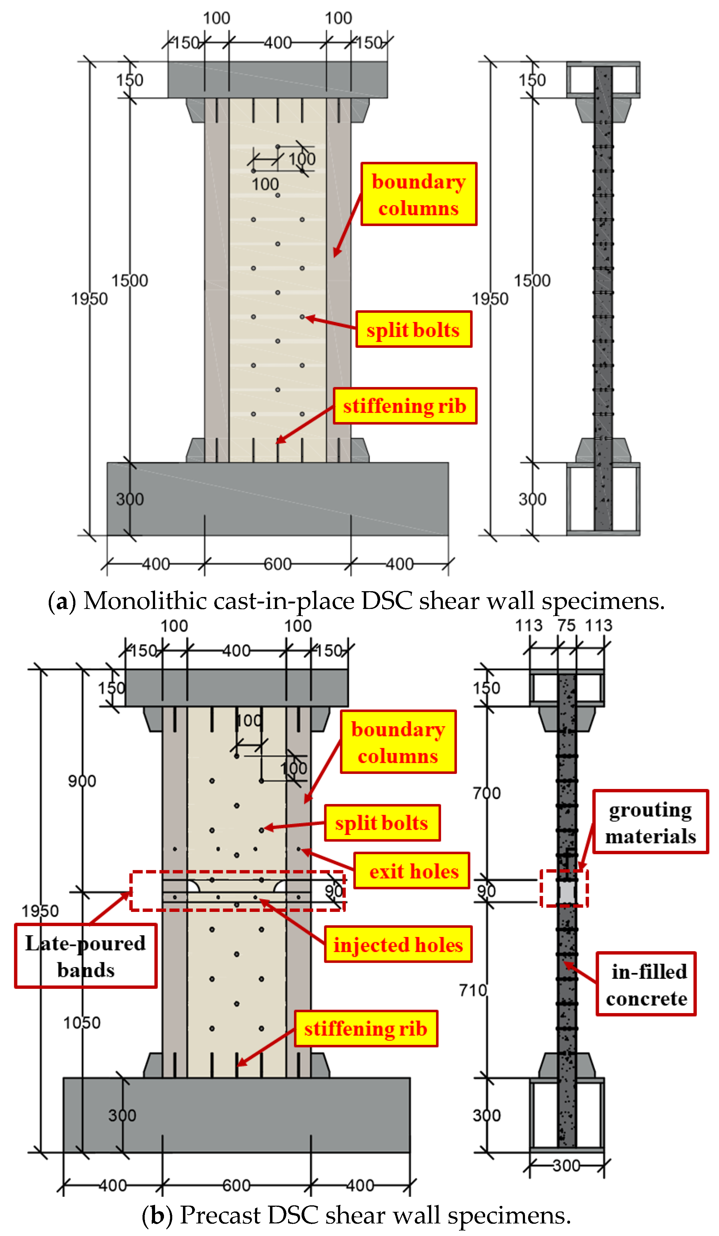
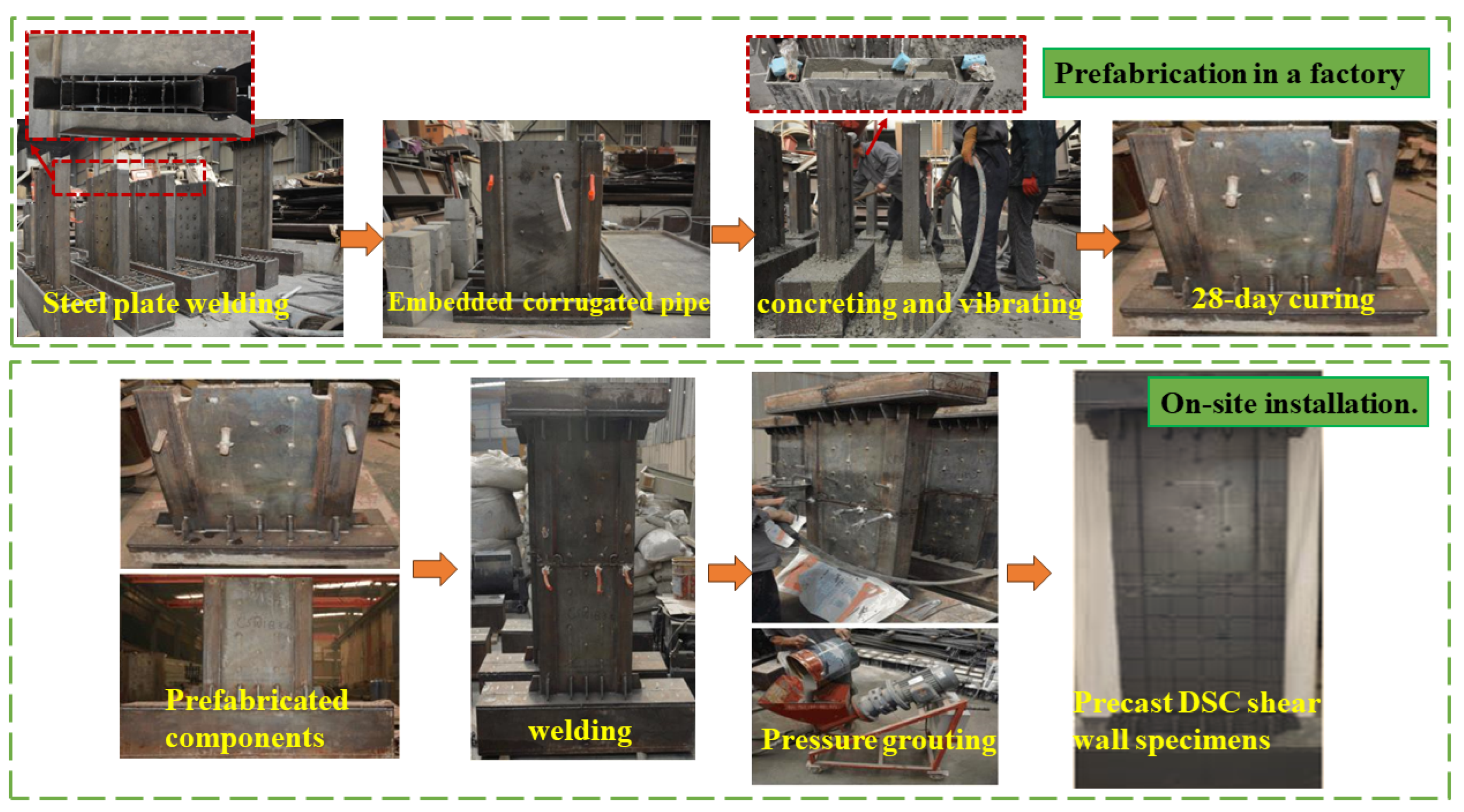
2.1. Specimen Design and Fabrication

Three half-scale DSC shear wall specimens were designed according to a prototype building to evaluate the seismic behavior of precast shear wall. The variables in the DSC shear wall specimens were the fabrication process (monolithic cast-in-place or precast) and axial compression ratio (0.2 or 0.4). The three test specimens were named SWC-0.4, SWP-0.4, and SWP-0.2, with “SW” indicating shear wall. The letter “C” or “P” indicate the monolithic cast-in-place or precast as the fabrication process of the DSC shear wall specimens, respectively, and the number indicates the axial compression ratio. The details of the DSC shear wall specimens are shown in Figure 2. All test specimens have a total height of 1950 mm, a width of 400 mm, and a thickness of 75 mm. Precast DSC shear wall specimens are comprised of upper and lower precast wall components, with the upper precast walls measuring 900 mm and the lower walls 1050 mm in height. The boundary columns are constructed from cold-formed concrete-filled square steel tubes with dimensions of 100 mm × 3 mm. Box-type loading beams are installed at the top and foundation beams at the bottom of the DSC shear walls, complemented by 20–30 mm steel plates internally as stiffening ribs for increased stiffness. The loading beams feature a 300 mm × 150 mm cross-section, while the foundation beams measure 300 mm × 300 mm. The exterior steel plates of DSC shear wall were butt-welded to boundary columns with a weld quality of not less than grade 2. To ensure the collaboration between the steel plates and the infilled concrete in DSC shear wall specimens, a mixed connection method utilizing both split bolts and headed studs was employed. Split bolts were staggered with studs interspersed, maintaining a 100 mm interval. The layout of injected holes and exit holes in the upper and lower precast wall components and boundary columns is shown in Figure 2.
Figure 3 shows the fabrication process of the precast DSC shear wall specimens, taking SWP-0.2 as an example.
(1)
Weld the steel plates according to the blueprint.
(2)
Install corrugated pipes at the injected holes and exit holes of the precast wall components.
(3)
Cast concrete and cure for 28 days. After curing, roughen the surface of the infilled concrete to a minimum depth of 6 mm to enhance the bonding performance between the grouting materials and the infilled concrete of the precast wall component.
(4)
Hoist the upper precast wall components above the lower precast wall components, and weld them together after alignment.
(5)
Inject grouting materials into the corrugated pipes of the lower precast wall components until it flows out from the grouting exit holes of the upper precast wall component. Seal the injected holes and exit holes with wire and execute pressure grouting on boundary columns individually.
(6)
After the curing of the grouting materials, cut off the corrugated pipes protruding from the surface of the precast DSC shear wall.
(7)
End the process with grinding and painting.

2.2. Material Properties

Three 150 mm cubic blocks for C30 concrete and three 40 mm × 40 mm × 160 mm prismatic blocks for grouting material were prepared and cured in the same conditions as the precast DSC shear wall specimens. After being cured for 28 days, the C30 cubic blocks underwent mechanical testing according to Chinese code GB/T50081-2019 [35] with the cubic compressive strength determined to be 43.2 MPa. The grouting material, assessed base on GB/T17671-1999 [36], showed a compressive strength of 50.7 MPa. According to GB/T 228-2010 [37], the material properties of the steel plates in the same batch as the DSC shear wall are summarized in Table 1.

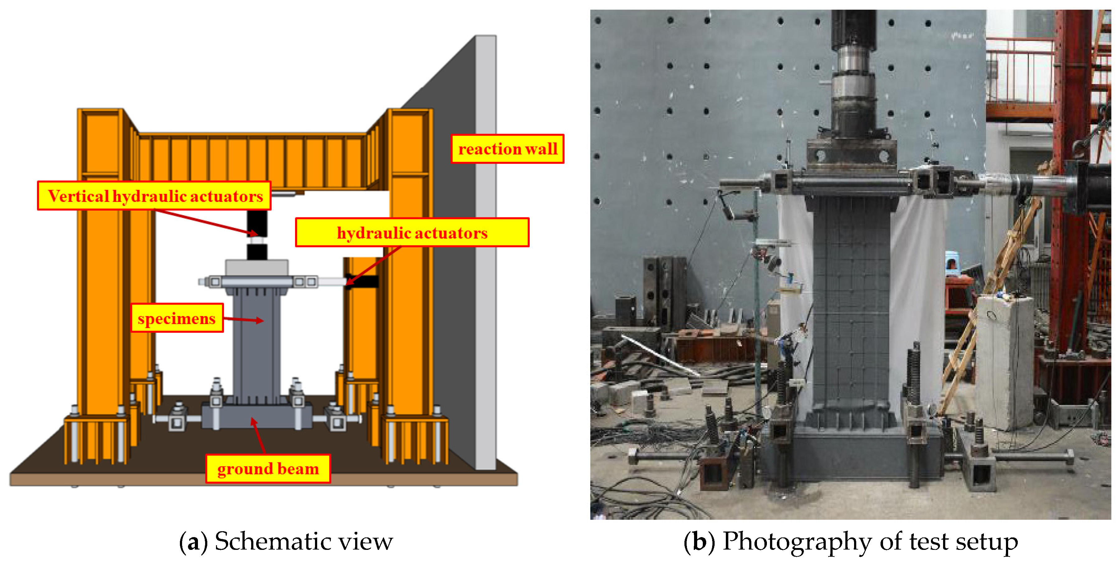
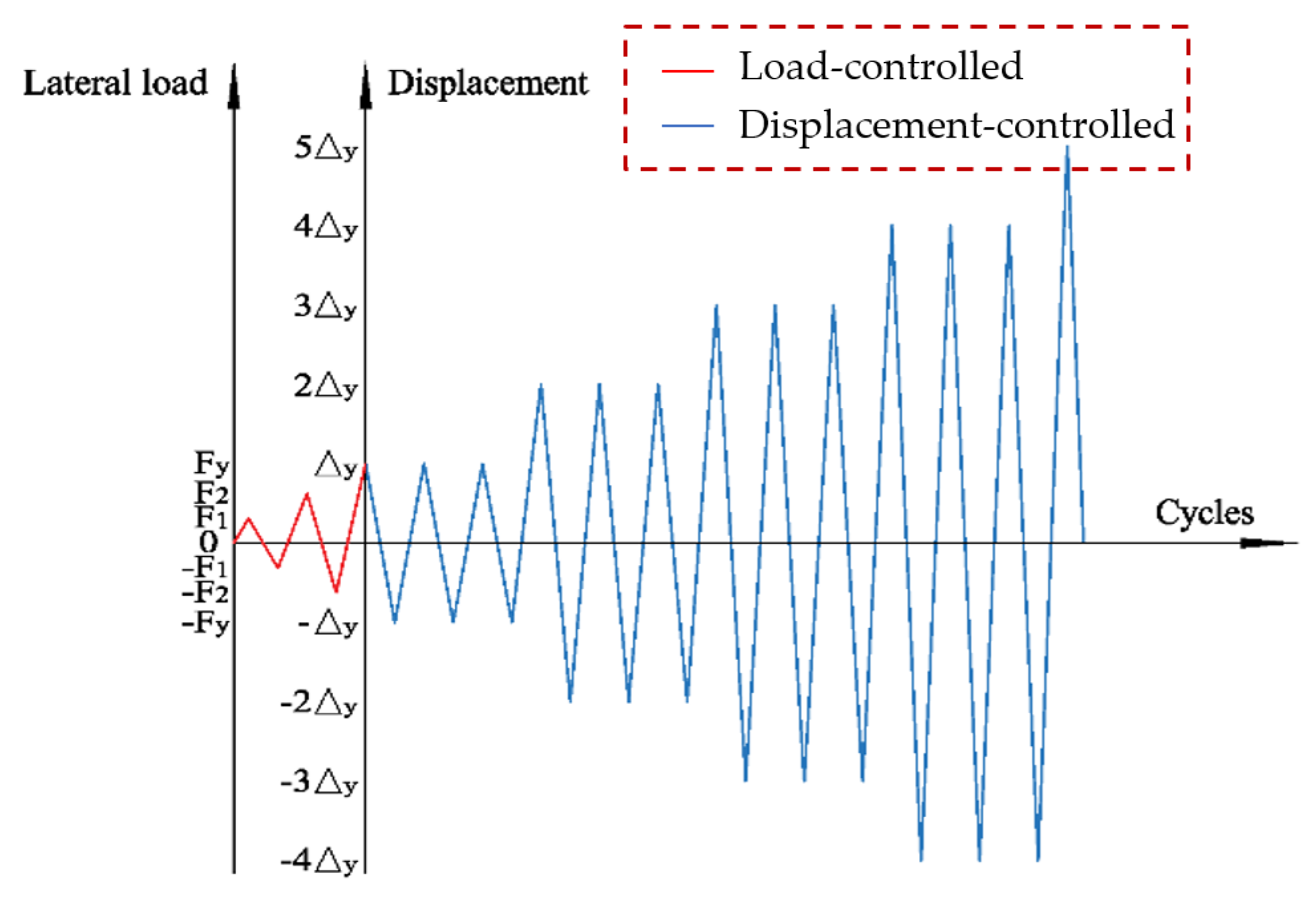
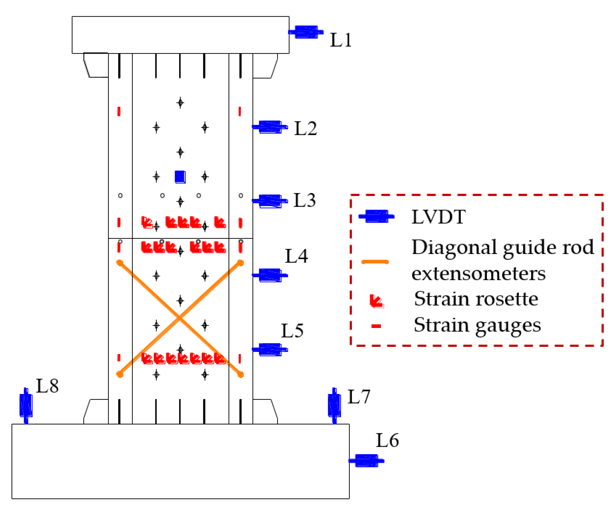
2.3. Test Setup and Loading Protocol

Figure 4 illustrates the loading setup. Prior to testing, four ground anchors were used to fix the ground beam on the rigid ground, and limit beams at both ends of the ground beam-constrained horizontal displacement to prevent the overall drift of the shear wall specimens during loading. The test beam was connected to a 1000 kN hydraulic actuators on the reaction wall through a threaded rod. The vertical hydraulic actuators, connected to the steel beam via a sliding support, applied a constant vertical load to the distribution beam.
In accordance with JGJ/T 101-2015 [38], the loading protocol in this test was a hybrid load-displacement control with the load-controlled during the elastic phase followed by a displacement-controlled phase, as shown in Figure 5. During the test, a constant vertical load was applied at the top of the distribution beam using different axial compression ratio. The axial compression ratios for SWC-0.4 and SWP-0.4 were 0.4 and 0.2 for SWP-0.2. A load-controlled pattern was adopted, and the load of each stage repeated once until the yielding of steel. Then, a displacement-controlled pattern was applied and loaded at an integer multiple of the yield displacement, which was repeated three times at each stage. The loading was terminated when the force descended to 85% of the peak load.
The arrangement of measuring points on the specimens is shown in Figure 6, including nine linear variable differential transducers (LVDTs), eight strain gauges, and eighteen strain rosette gauges. L1 to L5 are arranged along the height of the wall to monitor horizontal displacements. L6 to L8 are positioned to correct for the potential drifts and rotations of the foundation beam. Additionally, an out-of-plane LVDT (L9) is installed mid-shear wall to monitor the stability of the DSC shear wall specimens. Diagonal guide rod extensometers G1 and G2 are set at the lower precast wall components to measure shear deformation. Strain rosettes and strain gauges are placed at key locations to record the deformation progression in the late-poured bands and at the base of the wall panel. SWC-0.4 lacks strain and rosette gauges around the late-poured bands, but the other configurations remain consistent.

3. Results and Discussions
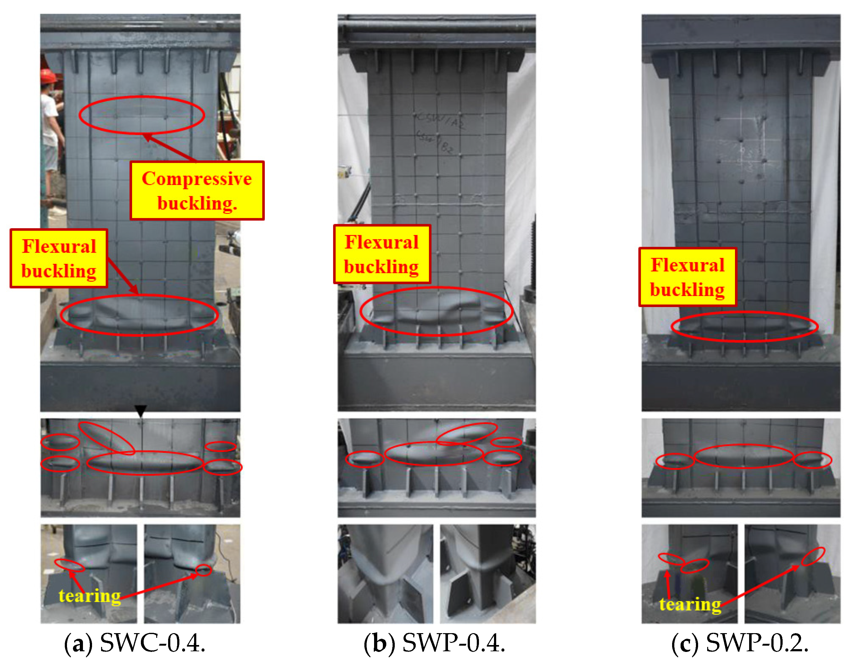
3.1. Failure Modes

Figure 7 shows the failure modes of all specimens. After vertical loading (axial compression ratio of 0.4), slight buckling occurred in the steel plate of SWC-0.4 specimen. This may be attributed to the insufficient vibration of the infilled concrete, resulting in a weak bonding performance between steel and concrete. In contrast, the SWP-0.4 and SWP-0.2 specimens with a precast DSC shear wall were no obvious phenomena in the vertical loading period. Hence, the monolithic cast-in-place DSC shear wall with excessive height makes it difficult to ensure adequate consolidation during construction due to the internal connectors.
In the traditional DSC shear wall specimen SWC-0.4, minor buckling began to appear and expanded in the exterior steel plates at a horizontal displacement angle of 1/173. When the horizontal displacement angle increased to 1/55, with the peak load at 334.4 kN, the buckling at the column and DSC shear wall base became more pronounced. Buckling waves were concentrated within 100 mm from the top of the stiffening rib. With increasing displacement, tearing occurred in the base of the column. Then, the concrete was crushed, resulting in a rapid decline in load capacity. The failure mode of SWC-0.4 is a typical flexural–compression failure, with tearing in the exterior steel plate at the base of the boundary column. Buckling waves at the base of the DSC shear wall extend into the boundary column, up to a height of 100 mm from the top of the stiffening rib.
The buckling development of SWP-0.2 and SWP-0.4 specimens were similar to SWC-0.4 at the initial stage. At the same axial compression ratio, buckling in the precast DSC shear wall specimen SWP-0.4 occurred at peak horizontal displacement angles of 1/100, delayed compared to the monolithic cast-in-place wall specimens due to pre-existing damage under the vertical loading phase for SWC-0.4. At a displacement angle of 1/67, the load peaked at 348.9 kN for specimen SWP-0.4, which was higher than that of SWC-0.4. Thereafter, buckling intensified at the base of the boundary columns and steel plates of the DSC shear wall. This occurred without steel plate tearing at the boundary columns in specimen SWP-0.4, attributed to the final loading cycle for CSW1 being conducted only once. Overall, the prefabricated specimen SWP-0.4 exhibits a similar failure process and load-bearing capacity to the monolithic cast-in-place specimens SWC-0.4, yet it offers a simpler construction process and superior concreting quality.
The buckling for SWP-0.2 occurred later, with a horizontal displacement angle of 1/83. This is primarily attributed to withstanding a lesser vertical load for specimen SWP-0.2. Subsequently, buckling in the steel plate and boundary column of SWP-0.2 developed more slowly compared to SWP-0.4, with an axial compression ratio of 0.4. When the horizontal displacement angle reached 1/55, the maximum horizontal for SWP-0.2 was 332.1 kN, less than that of the SWP-0.4 specimen. Overall, the damage severity for the SWP-0.2 specimen with low axial compression ratios was significantly less than that of the SWP-0.4 specimen. The buckling wave of the SWP-0.2 specimen penetrated within a 100 mm height range at the top of the stiffener rib, aligning horizontally with the damage region of boundary columns.

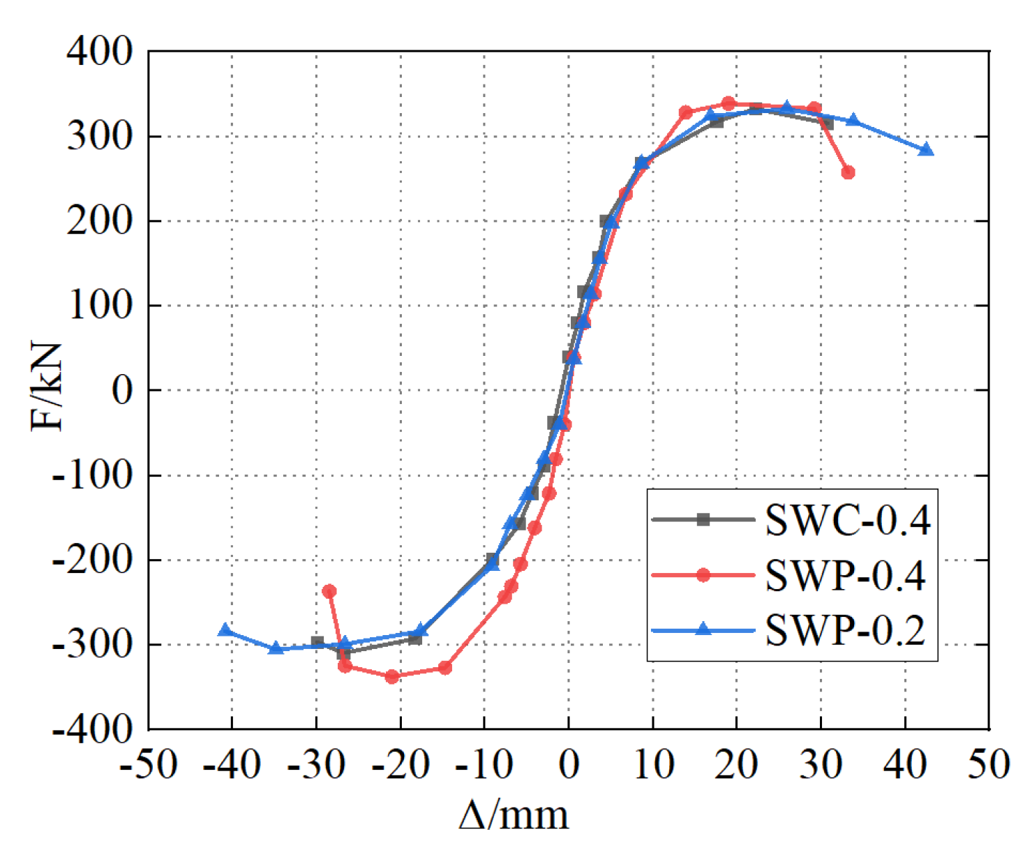
3.2. Hysteretic Behavior

Figure 8 presents the force–displacement relationship for each specimen under low reversed cyclic loading. Initially, loops evolve from spindle to bow shapes, indicating an increase in energy dissipation as the loop area enlarges. Progressive plastic deformation at the bottom of the DSC shear wall and boundary columns leads to increasing residual deformation with each load cycle, causing the loops to assume an S-shape. As displacement increased, yield began in the outer edge of boundary columns, causing concrete crushing and reduced stiffness. The hysteretic curve showed a pinching effect due to rapid plastic deformation. This is attributed to steel–concrete interface slip, steel buckling, and expansion of concrete cracks. After peak load, the specimen showed progressive deformation, reduced load-bearing capacity, and greater residual deformation, with pronounced buckling in the exterior steel plates, culminating in concrete crushing and failure. The hysteresis curves exhibit a full spindle shape, indicating that the designed DSC shear wall has good energy dissipation capacity under low reversed cyclic loading.
The precast DSC shear wall specimen (SWP-0.4) sustained higher peak loads compared to the monolithic cast-in-place DSC shear wall specimen (SWC-0.4). However, SWC-0.4 exhibited a fuller hysteresis curve with a more gradual descending branch, suggesting slightly better ductility and energy dissipation than SWP-0.4. This is attributed to the post-poured grouting material with higher strength but lower ductility compared to the infilled concrete of the precast DSC shear wall. Hence, the proposed precast DSC shear wall exhibits hysteresis performance under low reversed cyclic loading that is essentially equivalent to that of the cast-in-place. Compare SWP-0.4 and SWP-0.2 with different axial compression ratios, SWP-0.2 with a lower axial compression ratio showed a better ductility and energy dissipation capacity than the SWP-0.4 specimen, despite a notable decrease in peak load capacity.

3.3. Skeleton Curves and Ductility

The skeleton curve in Figure 9 is the envelope curve of the hysteresis curve constructed by linking the peak points at each loading stage. The curves exhibit an S-shape and can generally be divided into three parts: elastic stage, elastic–plastic stage, and declining stage. The skeleton curves of three specimens are very close in the elastic stage and diverge upon entering the plastic development stage. Initially, as the steel plate and concrete work together, the curve rises linearly with consistent initial stiffness. As displacement increases, the curve shift and slope decrease signifying stiffness degradation of DSC shear wall due to the yield of exterior steel plates in the bottom of boundary columns and shear wall. Subsequently, the curve falls due to concrete crushing and the irrecoverable deformation of steel plate.
Table 2 displays the characteristic values and ductility for the specimens. Py, Pm, and Pu represent yield, maximum, and ultimate loads, respectively; Δy, Δm, and Δu denote corresponding displacements. θy, θm, and θu are the mean drift angle at yield, peak, and failure stages, averaged from positive and negative loading displacements. The yield point is determined by Park’s method [39], and the ultimate point is identified where the load on the descending skeleton curve is 85% of the peak load. The ductility coefficient, μ, is defined as the ratio of ultimate displacement to yield displacement.
The peak load for SWC-0.4 is 334.4 kN, which is approximately 95% of that for SWP-0.4. This is attributed to the grouting material with a higher strength used in the late-poured bands of the precast DSC shear wall. The average yield and failure displacement angles for SWC-0.4 are approximately 1/160 and 1/40, respectively, which are 1.13 and 1.25 times those of SWP-0.4, indicating the superior deformation capacity of the precast DSC shear wall specimen. When the axial compression ratio increased from 0.2 to 0.4, the peak load of the precast DSC shear wall improved by 4.8%. Meanwhile, the average yield and failure displacement angles for specimen SWP-0.2 were 0.85 and 0.67 times that of SWP-0.4, respectively. Additionally, with an axial compression ratio of 0.4, the average yield and failure displacement angles of the precast DSC shear wall were approximately 1/180 and 1/50, respectively; at a ratio of 0.2, they were about 1/150 and 1/35, respectively. These values meet the Chinese code JGJ/T 380-2015, which stipulates that the elastic inter-story drift angle for steel plate composite shear walls should not exceed 1/400, and the elastic–plastic inter-story drift angle should not exceed 1/80.
The ductility factor of SWC-0.4 was 16% higher than that of SWP-0.4. While precast DSC shear walls show enhanced load-bearing capacity, their ductility is diminished compared to monolithic cast-in-place walls, a noteworthy consideration in seismic design. Overall, the ductility factors for all specimens exceeded three, indicating relatively good ductility of the monolithic and the precast DSC shear walls. The ductility factor of specimen SWP-0.4 was 0.76 times that of SWP-0.2, showing that the ductility decreases with an increase in axial compression ratio. Jafari et al. [40] also yielded similar results, indicating that excessive vertical load is detrimental to the seismic resistance of shear walls.

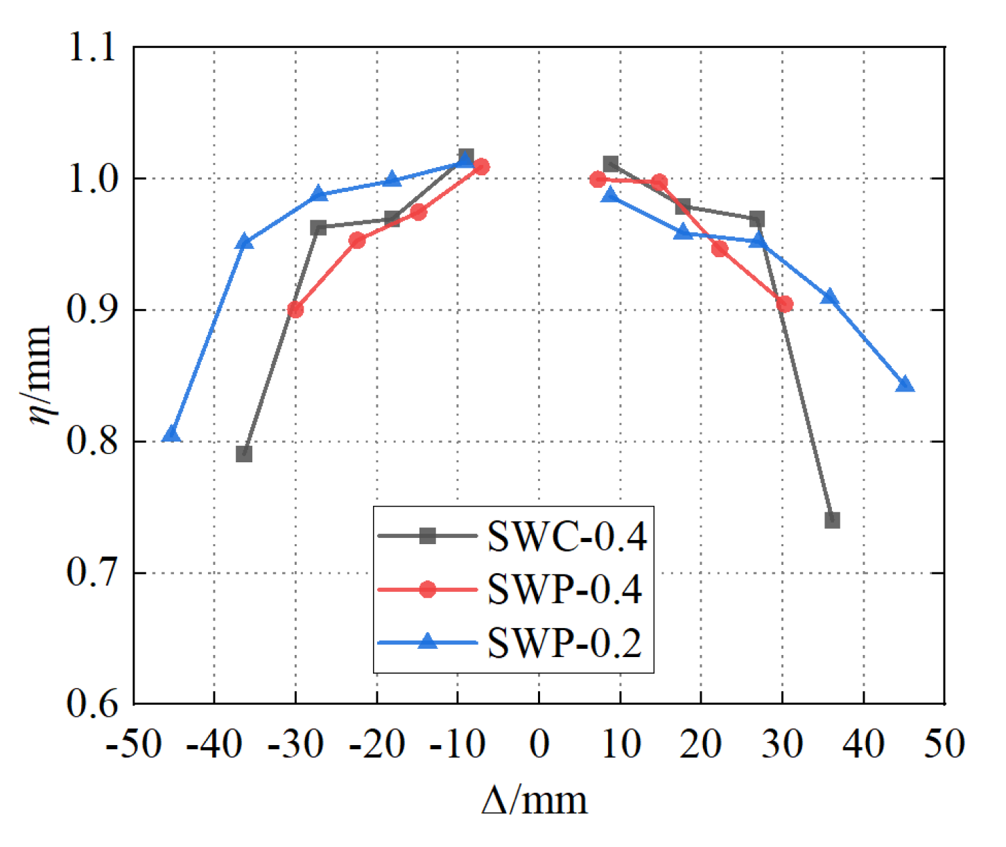
3.4. Bearing Capacity Degradation

Bearing capacity degradation is expressed by the bearing capacity degradation coefficient, η, which is the ratio of the last peak load to the first peak load at the same displacement amplitude. Figure 10 illustrates the bearing capacity degradation curves for each specimen. Initially, the bearing capacity degradation coefficient decreases slowly with increasing displacement. After reaching the peak load, the rate of bearing capacity degradation increases significantly, due to irreversible damage. The bearing capacity coefficients of the specimens are mostly between 0.7 and 1.0, indicating stable degradation.
The monolithic shear wall specimen exhibited less bearing capacity degradation compared to the precast shear wall specimens. The higher the axial compression ratio, the more significant the bearing capacity degradation for precast DSC shear wall. This is due to increased buckling of the square steel tube columns and the edge of the DSC shear wall.

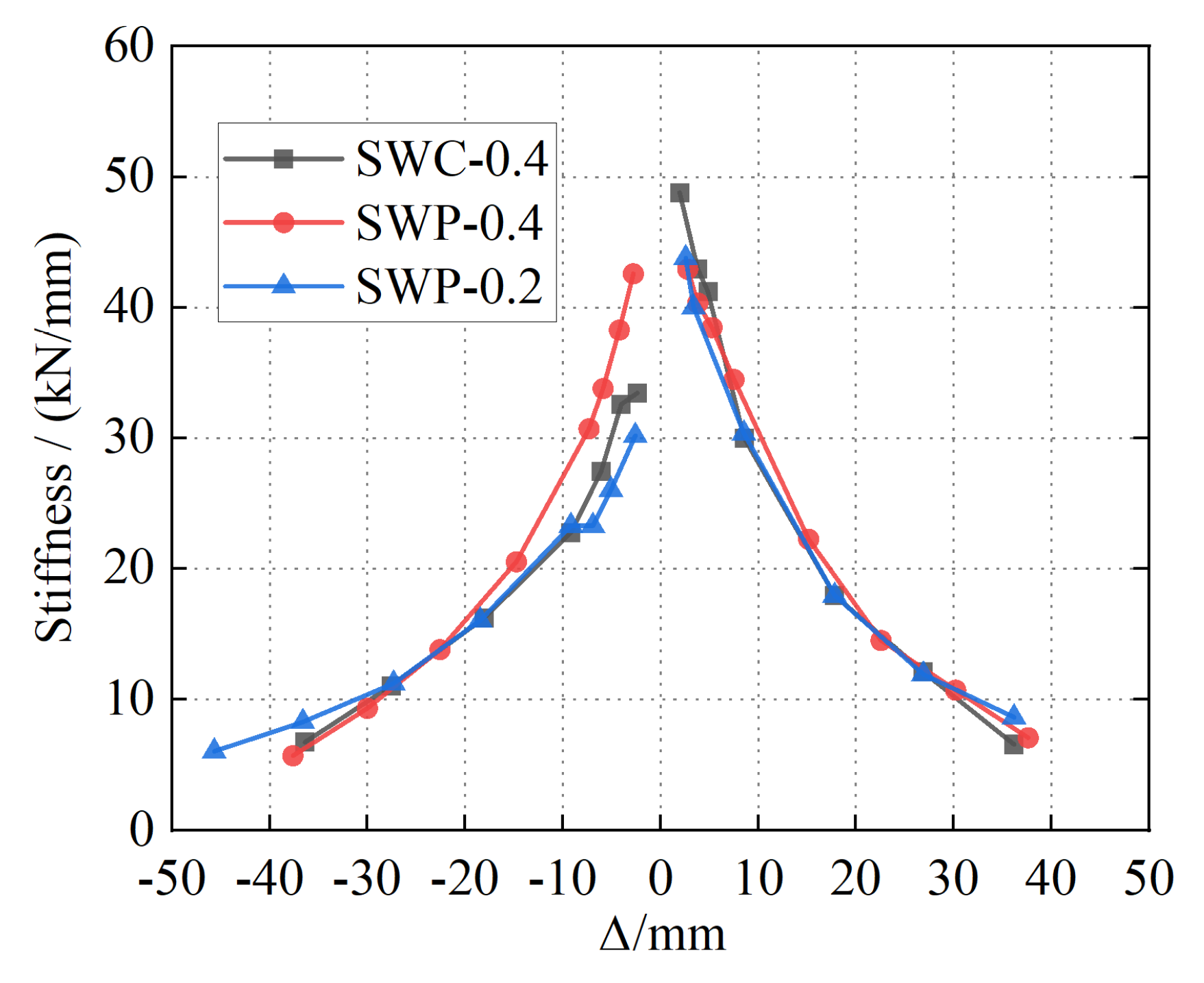
3.5. Stiffness Degradation

Stiffness degradation is characterized by cyclic stiffness, defined as the ratio of peak load to corresponding displacement for the same loading amplitude. Figure 11 depicts the stiffness degradation curves of each specimen. Initially, a rapid decrease in cyclic stiffness occurs due to interface damage between the exterior steel plate and infilled concrete. Entering the plastic phase, the specimen exhibits a slower cyclic stiffness reduction, attributable to concrete crack stabilization and the exterior steel plate’s effective confinement of infilled concrete. The SWP-0.4 specimen with rapid construction exhibited a faster decrease in cyclic stiffness compared to SWC-0.4 due to the integrity being slightly inferior to the precast DSC shear wall. The precast DSC shear wall under an axial compression ratio of 0.4 exhibited greater initial stiffness compared to a 0.2 ratio; however, it experienced a faster stiffness reduction during loading, resulting in more significant stiffness degradation.

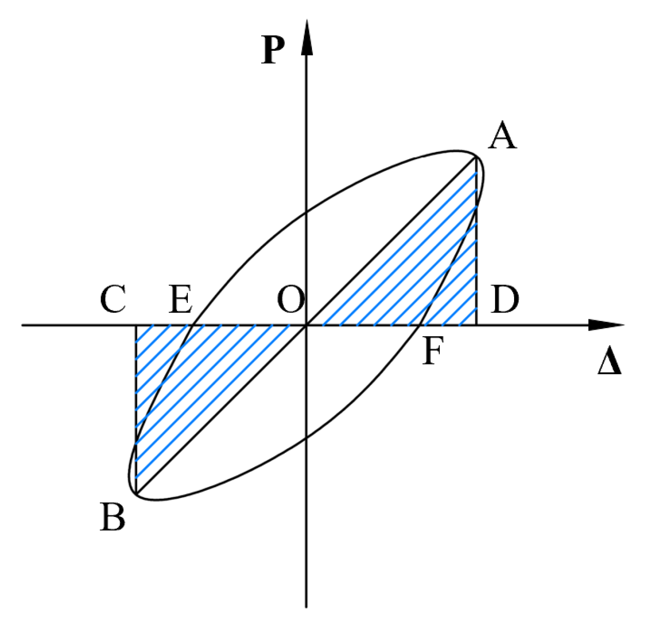
3.6. Energy Consumption

The energy dissipation capabilities of the specimens are quantified using the equivalent viscous damping coefficient, ξ. The equivalent viscous damping is normalized against an equivalent elastic cycle to denote the hysteretic energy dissipation. The equivalent viscous damping ratio for the DSC shear wall specimens is determined using Equation (1).
ξ = S ABCD 2 π ( S OCF + S OAE )
where SABCD represents the area of the hysteresis loops, while SOCF and SOAE denote the summed triangular areas, as illustrated in Figure 12.
Figure 13 presents the curves correlating with the equivalent viscous damping coefficient with displacement. Generally, all the specimens exhibit similar damping properties. Initially, the specimens’ equivalent viscous damping ratios decreased until reaching a displacement near 10 mm. Subsequently, the equivalent viscous damping coefficient exhibited an increasing trend.
It can be inferred that under the same displacement increment conditions, the precast DSC shear wall with higher equivalent viscous damping coefficient has a superior energy dissipation capability than the monolithic DSC shear wall. Additionally, the equivalent viscous damping coefficient of the precast DSC shear wall increases with the increasing axial compression ratio.

3.7. Analysis of Lateral Deformation

The lateral deformations of shear walls are analyzed using displacement measurements at various heights. L1 to L6 can measure the horizontal displacement of the shear wall at heights of 0 mm, 300 mm, 600 mm, 900 mm, 1200 mm, and 1500 mm. Figure 14 presents the distribution of lateral deformation along the height of the precast DSC shear wall specimen SWP-0.4, where H is the height of SWP-0.4. The graph reveals that the horizontal displacement of the precast DSC shear wall was initially linear. As it entered the plastic phase, the horizontal displacement increased more rapidly and displayed a bent deformation.

4. Finite Element Analysis

4.1. Description of the FE Model

4.1.1. Material Constitutive

To further investigate the behavior of the precast DSC shear wall subjected to low reversed cyclic loading, a finite element (FE) model was developed using ABAQUS. The constitutive relationship of the steel was defined using a tri-linear model, determined by the elastic modulus, yield strength, and ultimate strength measured from material tests discussed in Chapter 2. The stress–strain relationship of the infilled concrete and grouting material was obtained from prior material property tests, and the mechanical properties were simulated by the concrete damage plasticity (CDP) model in the Abaqus with default parameters: Poisson’s ratio (0.2), dilation angle (30), eccentricity (0.1), fb0/fc0 (1.16), K (0.667), and viscosity (0.005). Damage factors for tension and compression, based on the energy equivalence principle, were capped at 0.95 to represent the damage progression of concrete [41].

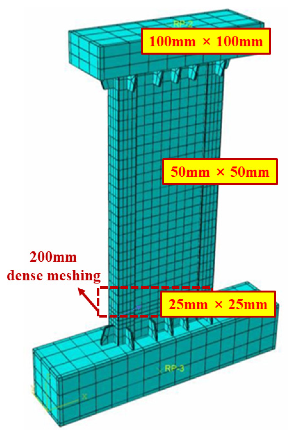
4.1.2. Establishment of FE Model

The FE model with reasonable simplification was established according to the test setup. The model was composed of the precast wall units, the after-casting unit, the loading beam, and the foundation beam, which were all simulated by 8-node solid elements (C3D8R). This study did not consider the loading and foundation beams, which were instead treated as idealized infinite rigid bodies. The interface between the square steel tube columns as well as the exterior steel plate of shear walls and the infilled concrete is defined by hard contact, and tangential interaction uses the Coulomb friction model with a friction coefficient of 0.4, based on studies. All steel components are connected using “tie” constraints. Stress at the load points is mitigated by a central coupling point RPl at the beam’s top for vertical loads, and RP2 at the beam’s side for horizontal loads. The foundation beam was completely fixed.
A more refined mesh improves accuracy but increases the computational time significantly. To balance accuracy and efficiency, a standard mesh size of 50 mm × 50 mm is used for the precast double-skin composite shear wall models. For buckling and tearing regions near the wall and columns base, a finer 25 mm × 25 mm mesh is applied, as shown in Figure 15. The mesh for foundation and loading beams is coarser, at 100 mm × 100 mm.

4.2. Verification of the FE Model

4.2.1. Comparison of Hysteretic Behavior

Figure 16 illustrates a comparison between the hysteretic curves of three specimens from FE simulations and experimental observations. To improve the working efficiency, FE models used a reduced displacement loading step compared to actual tests. The FE models successfully captured the hysteretic curve characteristics, such as initial stiffness, peak load, stiffness degradation, strengthening degradation, and pinching effects. However, for the precast DSC shear wall specimens, like SWP-0.2, the modeled pinching was less severe than the observed experimental results, attributed to the difficulty in simulating the interaction at the interface between new and old concrete under exterior steel plate confinement. Generally, finite element simulations may not fully align with experimental results, yet their precision can be maintained within an acceptable margin. More precise models are required in subsequent research to improve the accuracy of this study.

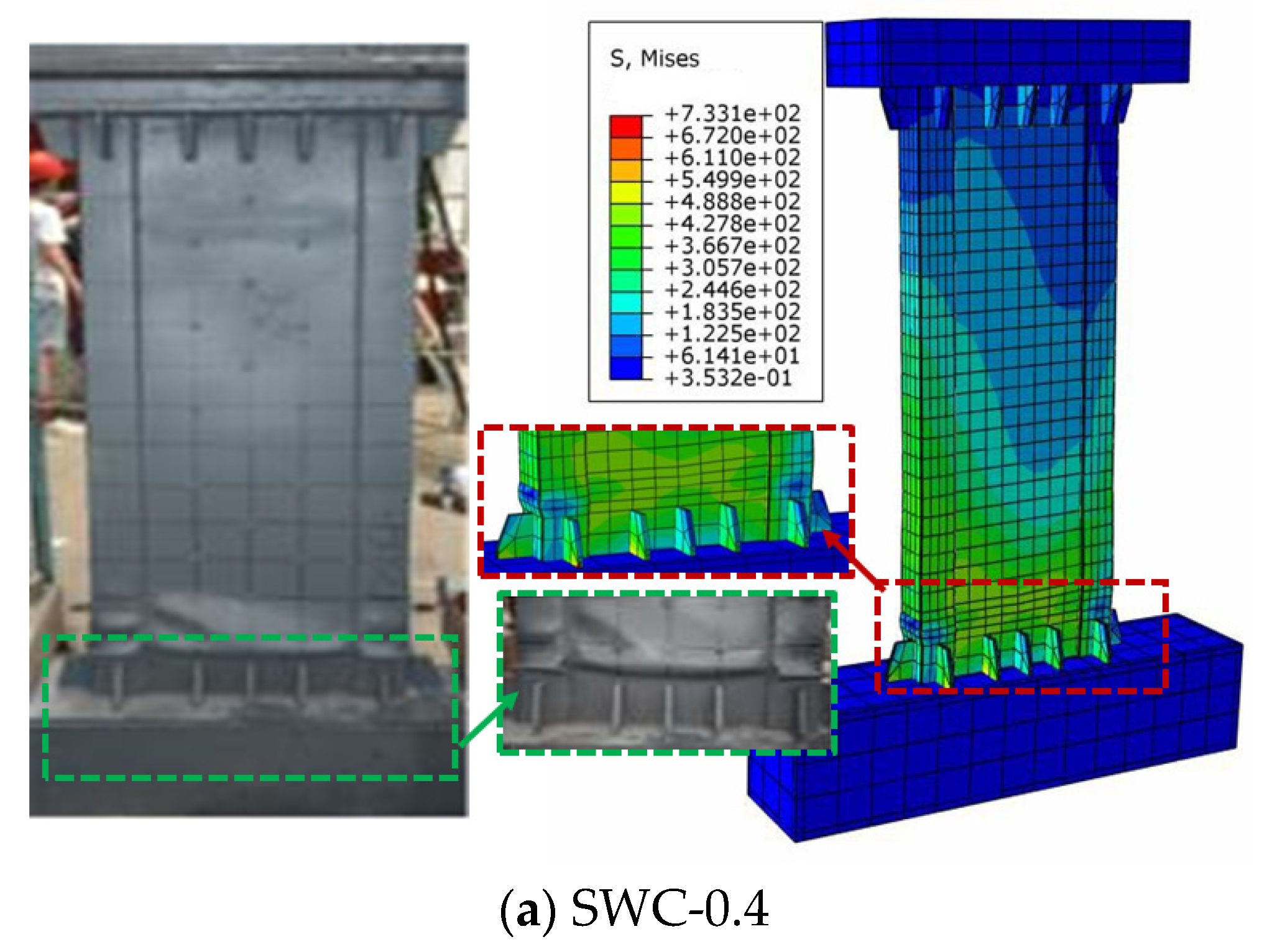
4.2.2. Comparison of Failure Modes

Figure 17 illustrates a comparison between typical failure modes of specimens from FE simulations and experimental observations. Generally, the established FE model under low reversed cyclic loads can reasonably predict the failure modes of monolithic cast-in-place and precast DSC shear walls in the test. For the monolithic cast-in-place DSC shear wall specimens (e.g., SWC-0.4), the buckling deformation occurred and intensified in buckling waves region within a 200 mm region from the base of shear wall. The failure mode of SWC-0.4 is typical flexural compression failure, with tearing in the corners of steel plates of the boundary column. Meanwhile, a high level of von Mises stress was observed in the buckling waves region and the boundary column region where the tears appeared in the tests. For the precast DSC shear wall specimens like SWP-0.2 and SWP-0.4, the buckling deformation in the buckling waves region and severe deformation at the boundary column were well simulated by the FE models. A high level of von Mises stress developed in a smaller range of the exterior steel plate, which was consistent with experimental results.

4.3. Stress Maps of Concrete and Steel

Despite the strain gauges on the steel plate, comprehensive monitoring of the deformation and stress of the exterior steel plate and the infilled concrete was challenging. Additionally, the cooperative deformation between the infill C30 concrete and site-cast grouting material was unclear in the experiments. Finite element models of the monolithic cast-in-place DSC shear wall specimens SWC-0.4 and the precast DSC shear wall specimens SWP-0.4 were analyzed at yield, peak, and failure points to assess stress distribution and plastic deformation under low reversed cyclic loading.

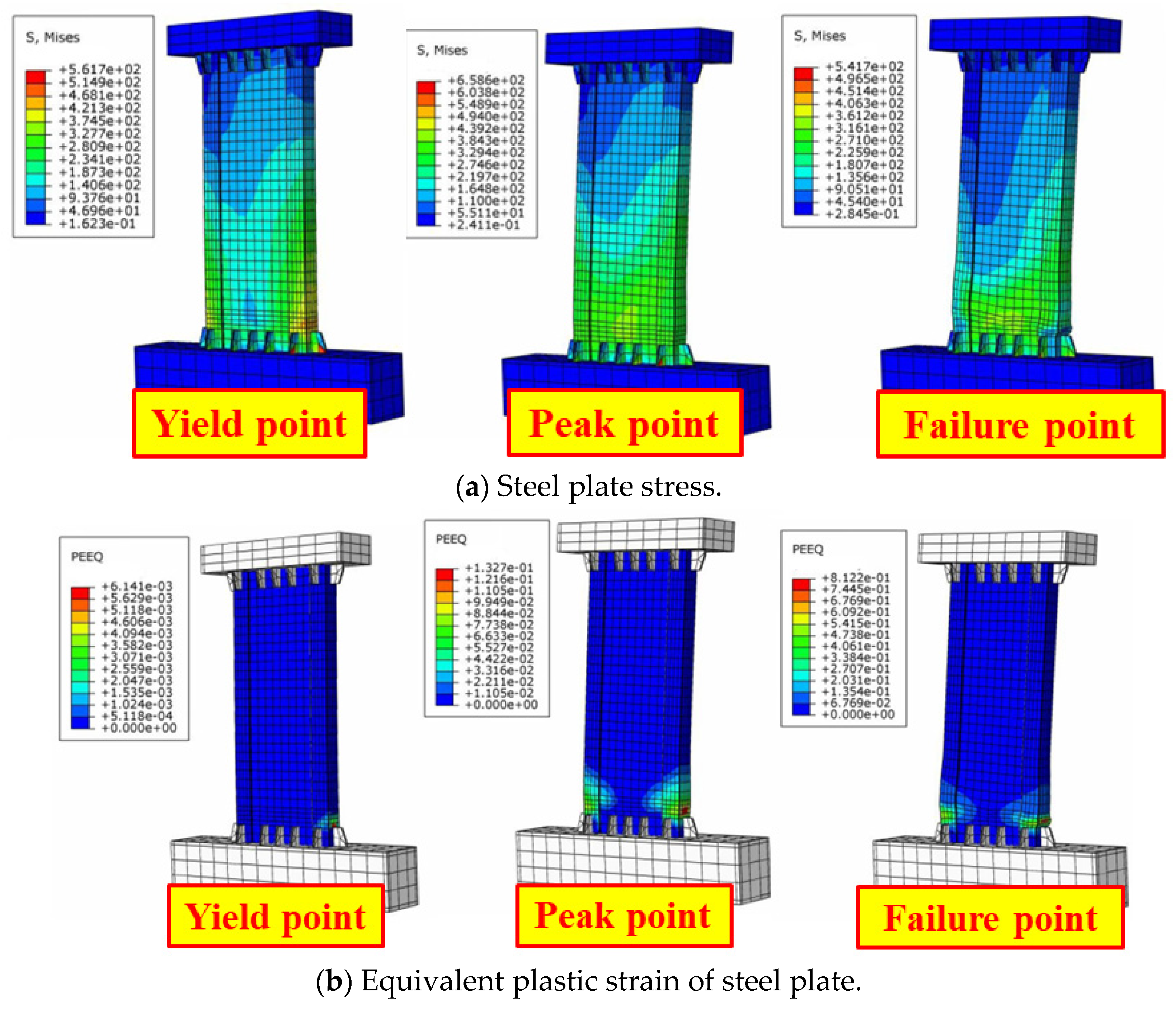
4.3.1. SWC-0.4 Specimen

Figure 18 and Figure 19 illustrate the stress–strain distribution of the exterior steel plates and the infilled concrete for the SWC-0.4 specimen at the respective yield, peak, and failure points. Yield points are identified by inflections on the hysteresis curves from FE model analysis. Equivalent plastic strain is used to indicate irreversible deformation. Higher equivalent plastic strain values indicate more extensive cumulative plastic deformation, pointing to a greater likelihood of material damage and failure.
At yield point of the monolithic cast-in-place DSC shear wall model, the von Mises stress on the exterior steel plates of the column base reached 425 MPa, equivalent to the yield stress of Q355B steel, with an equivalent plastic strain of 0.013. At the peak point of the SWC-0.4 specimen, most of the bottom steel plates yielded, experiencing a maximum stress of 486 MPa, which did not reach the ultimate strength of Q355B. Extensive plastic deformation occurred at the bottom of column, with a maximal equivalent plastic strain of 0.153. In the failure phase, the stress of exterior steel plates at the lower part of the column trended towards zero, while the equivalent plastic strain continued to increase, indicating severe damage or tearing for the concrete-filled steel tubular column. The von Mises stress reached yield stress within 100 mm above the top of the shear wall’s stiffening rib, aligning with the experimental observations.
For the infilled concrete, the stress gradually intensified as the load increased. At the specimen’s yield point, the majority of concrete had not reached its limit state. Meanwhile, minimal plastic strain of concrete was observed at the bottom of the boundary columns and shear wall. At the specimen’s peak point, the maximum concrete stress at the column foot was 21.02 MPa, below the concrete’s load-bearing capacity, whereas the equivalent plastic strain reached 0.080, exceeding the concrete’s ultimate compressive strain. This indicates that concrete crushing occurred before the peak load, but the bearing capacity of the monolithic cast-in-place DSC shear wall continued to increase as the steel entered a reinforcing stage. Compared to the bottom of the wall, the column base showed more pronounced plastic deformation. In the failure stage, concrete damage occurred around 100 mm above the stiffening rib, consistent with the observed experimental phenomenon that the concrete failure. Overall, the exterior steel plates effectively confined the infilled concrete, significantly enhancing the ductility and energy dissipation capacity of the DSC shear wall under seismic loads.

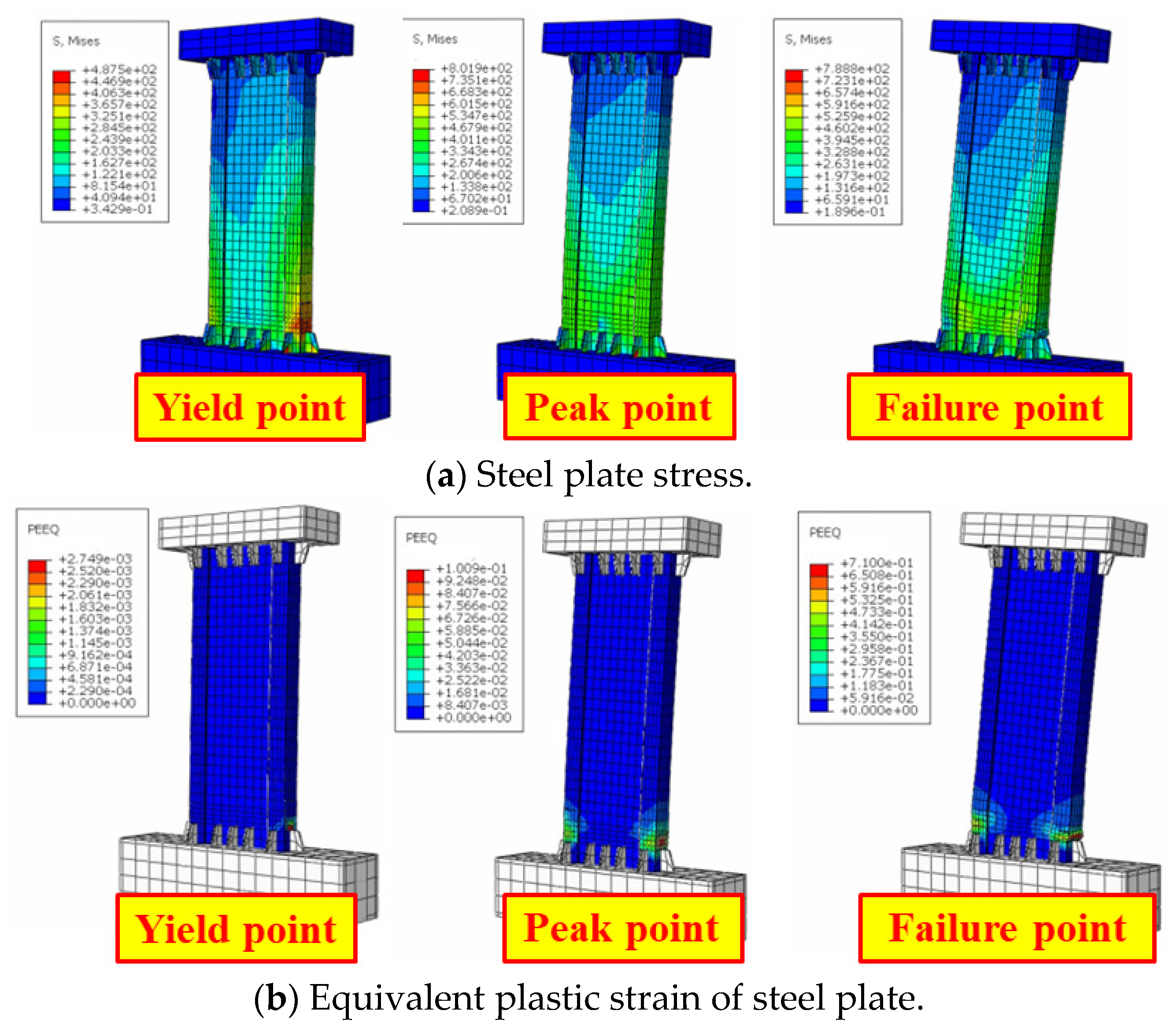
4.3.2. SWP-0.4 Specimen

Figure 20 and Figure 21 illustrate the stress–strain distribution of the exterior steel plates and the infilled concrete for the SWP-0.4 specimen at yield, peak, and failure points. At the yield point of FE model, the maximum von Mises stress in the boundary columns reached the 425 MPa yield stress of Q355B. The maximum equivalent plastic strain of model in the SWP-0.4 specimen was 0.008, less than that in the SWC-0.4 specimen model. Consequently, the maximum von Mises stress borne by the infilled concrete in SWC-0.4 model was also less than that in SWP-0.4 model, indicating that the precast DSC shear wall specimen preceded the monolithic cast-in-place DSC shear wall specimen in reaching yield. At the peak point of the specimen, the maximum von Mises stress at the column edges of the SWP-0.4 specimen reached 489 MPa, higher than SWC-0.4, which corresponds with the skeleton curves discussed in Section 2. At this stage, the maximum equivalent plastic strain of steel plate at the bottom of column peaked at 0.109, below that of SWC-0.4. As the specimen approached failure, the steel plate stress tended towards zero, with a continuously increasing equivalent plastic strain distributed within 200 mm above the top of the shear wall’s stiffening rib, indicating severe exterior steel plate damage. This corresponds with the observed buckling on the edges of boundary columns in the experimental phenomena.
As the load increased, the concrete stress gradually intensified. The plastic strain of the concrete appeared at the base of the shear wall and boundary columns, whereas the post-poured grouting material maintained elasticity. At the peak point of the overall model, the maximum concrete stress reached 24.38 MPa, surpassing that of SWC-0.4. The plastic deformation zone expanded to 200 mm above the stiffening rib. The enlargement of the plastic deformation zone enhanced the load-bearing capacity of the prefabricated component under seismic loads. In the failure phase, the equivalent plastic strain of concrete at the column base reached 0.087, exceeding the ultimate compressive strain, while the high-strength grouting materials remained in the elastic stage.
Comparing the stress–strain distribution of the monolithic cast-in-place DSC shear wall and precast DSC shear wall reveals that the new and old concrete between the horizontal connection region and precast components can achieve a cohesive performance for coordinated deformation. The damaged area in precast DSC shear wall is larger than in the monolithic cast-in-place DSC shear wall, enhancing the load-bearing capacity but reducing ductility slightly. Hence, the precast DSC shear wall with guaranteed concrete adhesion and steel plate welding quality demonstrates a seismic performance comparable to that of the cast-in-place counterparts.

4.4. Parametric Analysis

4.4.1. Parameter Settings

This study investigates the influence of geometric details and material strength on the load-bearing capacity of precast DSC shear walls using finite element parametric analysis. The parameters were the overall length (L), overall thickness (T), overall height (H), thickness of exterior steel plates (t), concrete strength, strength of grouting material, and steel strength. The structural configurations of SWP-0.4 corresponding to the general dimensions outlined in Section 2.1 served as the baseline reference models. Fifteen configurations of the precast DSC shear walls were analyzed, with parameter values varying within typical DSC shear wall ranges. Design parameters of individual configurations are shown in Table 3.

4.4.2. Influence of Shear Wall Parameters

Figure 22a illustrates the correlation between the overall width of the specimens and their skeleton curves under low reversed cyclic loading. Widening from 400 mm to 600 mm or 800 mm improved the peak load capacity by 64.6% and 110.2%, respectively. This indicated that increasing overall component width would enhance the load-bearing capacity of precast DSC shear walls during an earthquake. However, wider walls lead to a more pronounced decline in post-peak behavior, indicative of higher degradation and less ductility. Concurrently, raising wall heights from 1000 mm to 1500 mm or 2000 mm decreased peak loads by 29.3% and 47.8%, respectively, as shown in Figure 22b. Higher walls also had a gentler post-peak slope, indicating improved ductility for the high precast DSC shear walls. Thus, it is essential to appropriately configure the height-to-width ratio of the precast DSC shear walls in seismic design. Figure 22c shows the effect of the overall thickness of precast DSC shear walls on the load–displacement curve. The data indicate a clear increase in peak load with greater wall thickness.

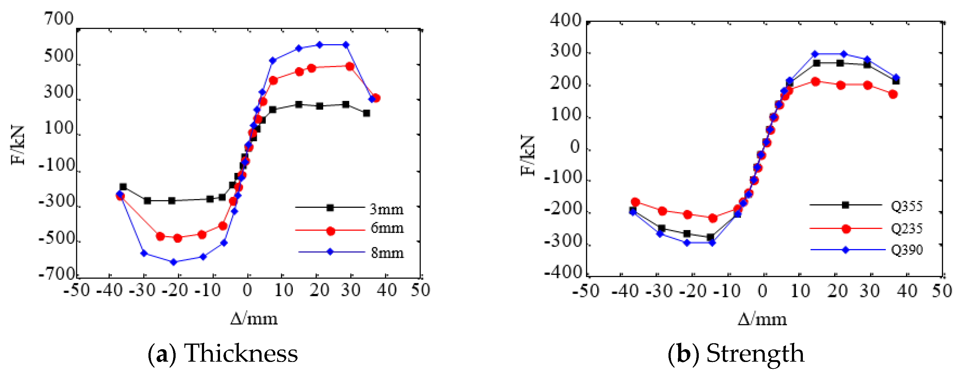
4.4.3. The Effect of Exterior Steel Plates

Increasing the exterior steel plate thickness significantly enhanced the peak load capacity, with a 72.5% increase for 6 mm and 118.6% for 8 mm, compared to 3 mm plates, as shown in Figure 23a. This was attributed to the enhanced confinement effect on the infilled concrete with increased exterior steel plate thickness. Additionally, excessively thick steel plates not only waste resources but also reduce seismic ductility. Upgrading the steel grade of exterior steel plates from Q235 to Q345 or Q390 steel yields peak load gains of 28.21% and 40.66%, showing a correlation between steel grade and load performance, as shown in Figure 23b. However, based on the design size of SWP-0.4, upgrading the steel grade does not significantly enhance the seismic resistance capability of the precast DSC shear walls.

4.4.4. The Effect of the Infilled Concrete

The peak load increases with the higher infilled concrete strength grades, showing a 6.0% and 11.3% rise when upgrading from C30 to C40 and C50, respectively, as shown in Figure 24a. The strength grade of the grouting material appears to have no effect on horizontal load, attributed to the grouting material remaining within the elastic range without plastic deformation. The seismic performance of the novel precast DSC shear walls is essentially equivalent to that of monolithic cast-in-place DSC shear walls. Enhancing the bonding performance between infilled concrete and grouting material is more effective for seismic enhancement than increasing concrete strength.

5. Conclusions

This paper studied the effect on seismic performance of precast DSC shear walls with on-site welding and cast grouting. Three half-scale DSC shear wall specimens including two precast DSC shear walls with horizontal connection region specimens and monolithic cast-in-place DSC shear wall specimens were tested under reversed cyclic loading. Finite element models were used for stress mechanism analysis and parametric study. The conclusions are as follows:
All specimens demonstrated satisfactory seismic performance and cooperative deformation capacity. The precast DSC shear wall with horizontal connection region specimens and on seismic performance monolithic cast-in-place DSC shear wall specimen exhibited compression-bending failure. The damage range of specimens was within a height range of 100 mm to 200 mm from the bottom of the shear wall.
With guaranteed welding quality and concrete bonding performance, precast DSC shear wall specimens with a horizontal connection region offered high construction efficiency and standardized components on-site. The SWP-0.4 specimen showed superior load-bearing capacity, deformation capability, and energy dissipation compared to SWC-0.4, with slower stiffness degradation due to improved component quality. However, on the monolithic cast-in-place DSC shear wall specimen SWC-0.4 exhibited better ductility under seismic loads.
An increased axial compression ratio enhanced the load-bearing and energy dissipation capacities of precast DSC shear walls by improving the constraint effect of the exterior steel plates on the infilled concrete. However, the SWP-0.4 specimen with a higher axial compression ratio resulted in more significant stiffness and strength degradation and poorer ductility compared to SWP-0.2.
Parametric analysis under low reversed cyclic loading revealed a positive correlation between the width, thickness, steel plate thickness, infilled concrete strength, steel strength, and peak load-bearing capacity of prefabricated double steel plate shear walls, with the shear wall height negatively correlated. The strength of the post-cast grouting material had a negligible impact on the load-bearing capacity.

Author Contributions

Conceptualization, H.L.; methodology, H.L., N.S. and X.F.; software, N.S.; formal analysis, H.L.; investigation, X.F. and J.Z.; supervision, H.L., N.S. and X.F.; funding acquisition, H.L. All authors have read and agreed to the published version of the manuscript.

Funding

This research was funded by the Higher Education Natural Science Research Project of Hebei Province, China (QN2024290).

Data Availability Statement

All relevant data are within the paper.

Conflicts of Interest

The authors declare no conflicts of interest.

References

  1. Yang, J.; Yang, Y.; Deng, L.; Sun, B.; Gu, Z.; Zeng, L.; Zhao, S. Seismic Behaviors of Prefabricated Reinforced Concrete Shear Walls Assembled with a Cast-in-Place Vertical Joint. Buildings 2023, 13, 3013. [Google Scholar] [CrossRef]
  2. Xu, G.; Wang, Z.; Wu, B.; Bursi, O.S.; Tan, X.; Yang, Q.; Wen, L. Seismic performance of precast shear wall with sleeves connection based on experimental and numerical studies. Eng. Struct. 2017, 150, 346–358. [Google Scholar] [CrossRef]
  3. Zheng, Y.; Guo, Z.; Guan, D.; Zhang, X. Parametric study on a novel grouted rolling pipe splice for precast concrete construction. Constr. Build. Mater. 2018, 166, 452–463. [Google Scholar] [CrossRef]
  4. GB 50011-2010; Code for Seismic Design of Buildings. Ministry of Housing and Urban-Rural Development of the People’s Republic of China: Beijing, China, 2008. (In Chinese)
  5. CI. ACI 318-19; Building Code Requirements for Structural Concrete and Commentary. American Concrete Institute: Farmington Hills, MI, USA, 2019.
  6. EN. Eurocode 8; Design of Structures for Earthquake Resistance–Part 1: General Rules, Seismic Actions and Rules for Buildings. European Committee for Standardization: Brussels, Belgium, 2004.
  7. Qian, K.; He, P.; Deng, N.; Li, H. Impact of concrete strength on seismic behavior of T-shaped double-skin composite walls. Eng. Struct. 2021, 236, 112039. [Google Scholar] [CrossRef]
  8. Ji, X.; Jiang, F.; Qian, J. Seismic behavior of steel tube–double steel plate–concrete composite walls: Experimental tests. J. Constr. Steel Res. 2013, 86, 17–30. [Google Scholar] [CrossRef]
  9. Nie, J.-G.; Hu, H.-S.; Fan, J.-S.; Tao, M.-X.; Li, S.-Y.; Liu, F.-J. Experimental study on seismic behavior of high-strength concrete filled double-steel-plate composite walls. J. Constr. Steel Res. 2013, 88, 206–219. [Google Scholar] [CrossRef]
  10. Hu, H.-S.; Nie, J.-G.; Eatherton, M.R. Deformation capacity of concrete-filled steel plate composite shear walls. J. Constr. Steel Res. 2014, 103, 148–158. [Google Scholar] [CrossRef]
  11. Nie, J.-G.; Ma, X.-W.; Tao, M.-X.; Fan, J.-S.; Bu, F.-M. Effective stiffness of composite shear wall with double plates and filled concrete. J. Constr. Steel Res. 2014, 99, 140–148. [Google Scholar] [CrossRef]
  12. Chen, L.; Mahmoud, H.; Tong, S.-M.; Zhou, Y. Seismic behavior of double steel plate–HSC composite walls. Eng. Struct. 2015, 102, 1–12. [Google Scholar] [CrossRef]
  13. Luo, Y.; Guo, X.; Li, J.; Xiong, Z.; Meng, L.; Dong, N.; Zhang, J. Experimental Research on Seismic Behaviour of the Concrete-Filled Double-Steel-Plate Composite Wall. Adv. Struct. Eng. 2015, 18, 1845–1858. [Google Scholar] [CrossRef]
  14. Zhang, X.; Qin, Y.; Chen, Z.; Jie, L. Experimental behavior of innovative T-shaped composite shear walls under in-plane cyclic loading. J. Constr. Steel Res. 2016, 120, 143–159. [Google Scholar] [CrossRef]
  15. Zhang, X.; Qin, Y.; Chen, Z. Experimental seismic behavior of innovative composite shear walls. J. Constr. Steel Res. 2016, 116, 218–232. [Google Scholar] [CrossRef]
  16. Ji, X.; Cheng, X.; Jia, X.; Varma, A.H. Cyclic In-Plane Shear Behavior of Double-Skin Composite Walls in High-Rise Buildings. J. Struct. Eng. 2017, 143, 04017025. [Google Scholar] [CrossRef]
  17. Guo, L.; Wang, Y.; Zhang, S. Experimental study of rectangular multi-partition steel-concrete composite shear walls. Thin-Walled Struct. 2018, 130, 577–592. [Google Scholar] [CrossRef]
  18. Huang, S.-T.; Huang, Y.-S.; He, A.; Tang, X.-L.; Chen, Q.-J.; Liu, X.; Cai, J. Experimental study on seismic behaviour of an innovative composite shear wall. J. Constr. Steel Res. 2018, 148, 165–179. [Google Scholar] [CrossRef]
  19. Yan, J.-B.; Li, Z.-X.; Wang, T. Seismic behaviour of double skin composite shear walls with overlapped headed studs. Constr. Build. Mater. 2018, 191, 590–607. [Google Scholar] [CrossRef]
  20. Goman, H.; Liu, P.; Yin, C.; Ching, R.; Liu, M.; Zhu, L. Design and study on super high-rise structural system of Beijing Fortune Plaza 2 office tower. Build. Struct. 2009, 39, 1–8. [Google Scholar]
  21. Liu, P.; Yin, C.; Cheng, Y.; Zhu, Y.S.; Liu, Y.B.; Wu, H.; Li, X.; Yang, M.L.; Liu, H.; Li, Z.X. Structural design and research of Beijing CBD Core Area Z15 plot China Zun Tower. Build. Struct. 2014, 44, 1–8. [Google Scholar]
  22. Ge, D.; Zhang, B.; Wei, J.; Zhou, W. Welding of Main Tower at Stage a of World Trade Center Phase III. Archit. Technol. 2008, 39, 265–269. [Google Scholar]
  23. Lv, X.; Dong, Y.; Ding, Z. Study on seismic behavior of steel reinforced concrete wall. Earthq. Eng. Eng. Vib. 2006, 26, 101–107. [Google Scholar]
  24. Varma, A.H.; Malushte, S.R.; Sener, K.C.; Lai, Z. Steel-plate composite (SC) walls for safety related nuclear facilities: Design for in-plane forces and out-of-plane moments. Nucl. Eng. Des. 2014, 269, 240–249. [Google Scholar] [CrossRef]
  25. Sohel, K.; Liew, J.R.; Yan, J.; Zhang, M.; Chia, K. Behavior of Steel–Concrete–Steel sandwich structures with lightweight cement composite and novel shear connectors. Compos. Struct. 2012, 94, 3500–3509. [Google Scholar] [CrossRef]
  26. Chen, L.; Xia, D.; Liu, W.; Zhang, X. Experimental study on seismic behavior of double steel plates and concrete composite shear wall. China Civ. Eng. J. 2017, 50, 10–19. [Google Scholar]
  27. Mydin, M.; Wang, Y.C. Structural performance of lightweight steel-foamed concrete-steel composite walling system under compression. Thin-Walled Struct. 2011, 49, 66–76. [Google Scholar] [CrossRef]
  28. Zhu, J.-S.; Guo, Y.-L.; Wang, M.-Z.; Yang, X.; Zhu, B.-L. Strength design of concrete-infilled double steel corrugated-plate walls under uniform compressions. Thin-Walled Struct. 2019, 141, 153–174. [Google Scholar] [CrossRef]
  29. Zhu, J.-S.; Guo, Y.-L.; Wang, M.-Z.; Yang, X.; Pi, Y.-L. Seismic performance of concrete-infilled double steel corrugated-plate walls: Experimental research. Eng. Struct. 2020, 215, 110601. [Google Scholar] [CrossRef]
  30. Hutchinson, R.L.; Rizkalla, S.H.; Lau, M.; Heuvel, S. Horizontal Post-Tensioned Connections for Precast Concrete Load bearing Shear Wall Panels. PCI J. 1991, 36, 64–76. [Google Scholar] [CrossRef]
  31. Soudki, K.A.; Rizkalla, S.H.; Leblanc, B. Horizontal Connections for Precast Concrete Shear Walls Subjected to Cyclic Deformations Part 1: Mild Steel Connections. PCI J. 1995, 40, 78–96. [Google Scholar] [CrossRef]
  32. Soudki, K.A.; West, J.S.; Rizkalla, S.H.; Blackett, B. Horizontal Connections for Precast Concrete Shear Wall Panels Under Cyclic Shear Loading. PCI J. 1996, 41, 64–80. [Google Scholar] [CrossRef]
  33. Qian, J.; Peng, Y.; Qin, H. Tests on seismic behavior of pre-cast shear walls with vertical reinforcements grouted in holes and spliced indirectly. Build. Struct. 2011, 41, 7–11. [Google Scholar]
  34. Sun, J.; Qiu, H.; Lu, Y. Experimental study and associated numerical simulation of horizontally connected precast shear wall assembly. Struct. Des. Tall Spéc. Build. 2016, 25, 659–678. [Google Scholar] [CrossRef]
  35. GB/T 50081-2019; Standard for Test Methods of Concrete Physical and Mechanical Properties. China Building Industry Press: Beijing, China, 2019. (In Chinese)
  36. GB/T17671-1999; SBTS, Analysis Methods for Strength of Cement Mastic and Sand (ISO Methods). China Standards Press: Beijing, China, 1999. (In Chinese)
  37. GB/T 228.1-2010; Metallic Materials-Tensile Testing at Ambient Temperature. China Standards Press: Beijing, China, 2010. (In Chinese)
  38. JGJ/T 101—2015; Specification for Seismic Test of Buildings. China Architecture & Building Press: Beijing, China, 2015. (In Chinese)
  39. Park, R.; Priestley, M.J.N.; Gill, W.D. Ductility of Square-Confined Concrete Columns. J. Struct. Div. 1982, 108, 929–950. [Google Scholar] [CrossRef]
  40. Jafari, A.; Beheshti, M.; Shahmansouri, A.A.; Bengar, H.A. Cyclic response and damage status of coupled and hybrid-coupled shear walls. Structures 2024, 61, 106010. [Google Scholar] [CrossRef]
  41. Wang, X.; Ma, S.; Wu, W.; Fang, J.; Chen, Z. Tensile damage development and constitutive relationship establishment of recycled coarse aggregate concrete based on a double–interface numerical model. Constr. Build. Mater. 2023, 392, 131908. [Google Scholar] [CrossRef]
Figure 1. Details of the precast DSC shear wall.
Buildings 14 01617 g001
Figure 2. Details of the specimens.
Buildings 14 01617 g002
Figure 3. Fabrication process of the precast DSC shear wall specimens.
Buildings 14 01617 g003
Figure 4. Loading setup. (a) Schematic view; (b) Photography of test setup.
Buildings 14 01617 g004
Figure 5. Loading protocol.
Buildings 14 01617 g005
Figure 6. Arrangement of measuring points.
Buildings 14 01617 g006
Figure 7. Failure modes of the specimens.
Buildings 14 01617 g007
Figure 8. Hysteretic curves of specimens.
Buildings 14 01617 g008
Figure 9. Skeleton curves.
Buildings 14 01617 g009
Figure 10. The bearing capacity degradation curves for each specimen.
Buildings 14 01617 g010
Figure 11. The stiffness degradation curves.
Buildings 14 01617 g011
Figure 12. Definitions of equivalent viscous damping ratio.
Buildings 14 01617 g012
Figure 13. Equivalent viscous damping ratio-displacement curves.
Buildings 14 01617 g013
Figure 14. Lateral deformation of SWP-0.4.
Buildings 14 01617 g014
Figure 15. Typical FE mesh of the shear wall system.
Buildings 14 01617 g015
Figure 16. Comparison of hysteretic behavior from experimental results and simulations.
Buildings 14 01617 g016
Figure 17. Comparison of failure modes from experimental results and simulations.
Buildings 14 01617 g017aBuildings 14 01617 g017b
Figure 18. Stress and strain of exterior steel plates for SWC-0.4.
Buildings 14 01617 g018
Figure 19. Stress and strain of the infilled concrete for SWC-0.4.
Buildings 14 01617 g019
Figure 20. Stress and strain of exterior steel plates for SWP-0.4.
Buildings 14 01617 g020
Figure 21. Stress and strain of the infilled concrete for SWP-0.4.
Buildings 14 01617 g021aBuildings 14 01617 g021b
Figure 22. Influence of geometric details of shear wall.
Buildings 14 01617 g022
Figure 23. The effect of exterior steel plates.
Buildings 14 01617 g023
Figure 24. The effect of the infilled concrete.
Buildings 14 01617 g024
Table 1. Mechanical parameters of steel plates.
PositionYield Strength (MPa)Ultimate Tensile Strength (MPa)Elasticity Modulus (GPa)
Shear wall287.5422.5211
column305.2420.3213
Table 2. Characteristic values and ductility.
SpecimensDirectionPy (kN)y (mm)θyPm (kN)m (mm)θmPu (kN)u (mm)θuμ
SWC-0.4+250.87.6491/161334.422.531/61284.235.041/404.58
−232.4−10.88−309.9−26.74−263.4−39.153.60
SWP-0.4+261.77.7871/182348.918.931/76296.630.071/523.86
−252.0−8.610−252.0−20.74−285.6−27.323.17
SWP-0.2+249.07.8521/154332.025.911/50282.242.941/355.58
−230.2−11.70−306.9−34.45−260.9−42.453.63
Table 3. Design parameters of individual configurations.
NumberL (mm)H (mm)T (mm)t(mm)ConcreteGrouting MaterialSteel
SWP-Base
(SWP-0.4)
40015001003C40C50Q355
SWP-160015001003C40C50Q355
SWP-280015001003C40C50Q355
SWP-340010001003C40C50Q355
SWP-440020001003C40C50Q355
SWP-54001500703C40C50Q355
SWP-640015001303C40C50Q355
SWP-740015001006C40C50Q355
SWP-840015001008C40C50Q355
SWP-940015001003C30C50Q355
SWP-1040015001003C50C50Q355
SWP-1140015001003C40C60Q355
SWP-1240015001003C40C80Q355
SWP-1340015001003C40C50Q235
SWP-1440015001003C40C50Q390
Disclaimer/Publisher’s Note: The statements, opinions and data contained in all publications are solely those of the individual author(s) and contributor(s) and not of MDPI and/or the editor(s). MDPI and/or the editor(s) disclaim responsibility for any injury to people or property resulting from any ideas, methods, instructions or products referred to in the content.

