Article

Compressive Strength and Microstructure of Carbide Slag and Alkali-Activated Blast Furnace Slag Pastes in China

1
School of Material and Chemical Engineering, Henan University of Urban Construction, Pingdingshan 467036, China
2
School of Civil and Transport Engineering, Henan University of Urban Construction, Pingdingshan 467036, China
*
Authors to whom correspondence should be addressed.
Buildings 2024, 14(6), 1681; https://doi.org/10.3390/buildings14061681
Submission received: 3 April 2024 / Revised: 22 May 2024 / Accepted: 30 May 2024 / Published: 6 June 2024
(This article belongs to the Section Building Materials, and Repair & Renovation)

Abstract

:
The alkali-activated blast furnace slag is attracting significant attention in replacing Portland cement due to several characteristics similar to cement hydration. However, there are a few practical problems with commercial alkali activators, such as the fast setting time, relatively high costs, and significant CO2 emissions during preparation. Thus, discovering industrial residues possessing inherent alkalinity are urgent. This study proposes the use of carbide slag at levels of 0%, 5%, 10%, 15%, 20%, and 30% and alkali at levels of 1%, 2%, 3%, 4%, 5%, 6%, 8%, and 10% activated blast furnace slag. The compressive strength and microstructure of carbide slag and alkali-activated blast furnace slag (CAB) pastes were examined using X-ray diffraction analysis (XRD), Differential Scanning Calorimetry/Thermogravimetric Analysis (DSC/TG), Fourier transform infrared spectroscopy (FTIR) and Scanning electron microscopy (SEM). The results revealed that the addition of carbide slag produced more hydrotalcite-like phase as well as decreased the content of ettringite (AFt) and the calcium–silicate–hydrate (C-S-H) gel, which decreased the compressive strength of the CAB pastes. At the age of 28 days, when the dosage was 5%, 10%, 15%, 20%, and 30%, the compressive strength of CAB mixes decreased by 2.1%, 7.1%, 9.2%, 9.8%, and 28.1%, respectively. The addition of NaOH promoted the formation of AFt, and there was an optimum level of NaOH corresponding to the high compressive strength of paste. At the age of 3 days and 7 days, the compressive strength reached its maximum at the dosage of 6% NaOH, which was 24.8 MPa and 36.3 MPa, respectively. However, at the ages of 14 days and 28 days, the compressive strength increased as the dosage of NaOH increased to 5%, which was 43.3 MPa and 44.5 MPa, respectively. The water curing could both enhance the early and later strength, the compressive strength of 23.3 MPa was gained at 3 days, and this increased by 16.3%, 24.0% and 36.9% at 7 days, 14 days and 28 days, respectively. Therefore, water curing was suitable for the strength development of CAB pastes.

1. Introduction

Increasing global CO2 has contributed to global warming and extreme weather events [1]. Countries have reached a consensus on reducing CO2 emissions [2]. China is a major construction country and a major emitter of CO2. As one of China’s pillar industries, the construction industry plays a crucial role in promoting China’s economic development. However, it also consumes a large amount of construction materials and emits massive CO2 [3]. In 2020, the construction materials in China have emitted 1.48 billion tons of CO2. The cement industry is the largest carbon emitter in the construction materials industry, accounting for more than 80% of CO2 emissions [4]. With the accelerated development of urbanization in China, the total CO2 emissions from the Chinese cement industry will continue to increase if effective control measures are not taken. As a result, the preparation of low-carbon binders has been recognized as an effective measure to reduce the carbon emissions from the Portland cement industry [5]. Many studies have focused on the application of industrial waste by-products in construction materials [6,7,8,9,10].
In particular, the alkali-activated blast furnace slag is attracting significant attention due to several characteristics similar to cement hydration. Huang et al. [11] studied the kinetics of alkali–silica reaction-induced damage in alkali-activated granulated blast furnace slag and showed that it depended on the alkali concentration and activator type. Li et al. [12] discussed the effect of pH and temperature on the further slag hydration and demonstrated that the low temperature and high pH of solution contributed to the further slag reaction. Hruby et al. [13] carried out the resistance of alkali-activated blast furnace slag to acids and indicated that it deteriorated when affected by acids. Usherov-Marshak et al. [14] studied the hydration via calorimetric studies and thought that a high heat rate was a criterion in the case of alkali-activated blast-furnace slag cements. Li et al. [15] used CaCl2 and NaCl to improve the compressive strength of carbide slag-activated ground blast furnace slag and found that the addition of CaCl2 and NaCl promoted the reaction of carbide slag, and the contribution of CaCl2 was greater than NaCl. Lin et al. [16] investigated the soda residue-activated blast furnace slag and considered that the addition of 2.5–10% CaCl2 was beneficial for compressive strength improvement, and adding CaSO4 was harmful to the compressive strength. Laurent et al. [17] studied the effect of CaCl2 on the blast furnace slag hydration in blended cement and thought the CaCl2 improved the compressive strength by 50%.
In addition, Karam et al. [18] found that sediment delayed the reaction at early age but made a little contribution to the later age. Klimenko et al. [19] found interactions between sodium silicate and sand depended on the degree of dispersibility. Bilici et al. [20] revealed that the washing aggregate sludge waste reduced the compressive strength of alkali-activated mortar samples. Occhicone et al. [21] showed the compressive strength of red mud and blast furnace slag-activated materials up to 70 MPa. Niu et al. [22] incorporated the bioleached sulfidic mine tailings into alkali-activated blast furnace slag and displayed high compressive strength up to 90 MPa. Zhao et al. [23] revealed that the substitution ratio of steel slag could not exceed 15%; otherwise, the mechanical properties would be reduced. Feng et al. [24] reported that the addition of MgO and CaO improved the mechanical strength of alkali-activated blast furnace slag. Huang et al. [25] found that the cations and concentration have a great impact on the reaction process. Zhang et al. [26] showed that the optimal Na2O content of alkali-activated soda residue-blast furnace slag system was 3.0% considering the compressive strength. Despite the efforts of numerous researchers, the application of alkali-activated blast furnace slag at construction sites is very limited due to the existing commercial alkali.
Currently, the widely used commercial alkali activators are sodium hydroxide and sodium silicates [27]. However, there are a few practical problems with commercial alkali activators, such as fast setting time [28,29,30,31,32], relatively high costs [27,33] and significant CO2 emissions [34,35,36] during preparation. Therefore, the search for cheap and low-carbon activators that could replace commercial alkali has received a great deal of attention in recent years.
Carbide slag is an industrial waste resulting from the hydrolysis of calcium carbide for the preparation of acetylene [27], and it is estimated that China produced about 5.6 × 10⁷ tons of carbide slag per year [37]. However, carbide slag can only be used in the production of cement with a utilization rate of less than 40% [38]. Most carbide slag is stored in wet dam or dumps. This not only occupies a large amount of land but also leads to the salinization of surrounding land and contamination of nearby surface and groundwater sources [39]. Therefore, the recycling of carbide slag has attracted extensive interest from many researchers.
Additionally, carbide slag is mainly composed of Ca(OH)2, which is soluble in water and strongly alkaline [38]. Thus, carbide slag has the potential to replace commercial alkali for the preparation of an alkali-activated binder. Furthermore, alkali-activated blast furnace slag has the advantage of rapidly increasing strength even at room temperature [40]. Consequently, a carbide slag-activated blast furnace slag binder is prepared. Unfortunately, the excitatory activity of Ca(OH)2 from carbide slag to blast furnace slag is very poor, which still needs to be improved. Therefore, carbide slag blended commercial alkali as the activator activating blast furnace slag to prepare low-carbon binder is studied. In general, the principal hydration products with carbide slag and alkali-activated blast furnace slag pastes are similar to those found with pure alkali activated blast furnace slag pastes; however, the amount and timing of hydration products may be affected by the added constituents. These changes would then be reflected in properties, such as compressive strength. In order to understand and predict the performance of carbide slag and alkali-activated blast furnace slag pastes, it is useful to study the compressive strength and microstructure. The research results can provide a theoretical basis for the further utilization of carbide slag and blast furnace slag.

2. Materials and Methods
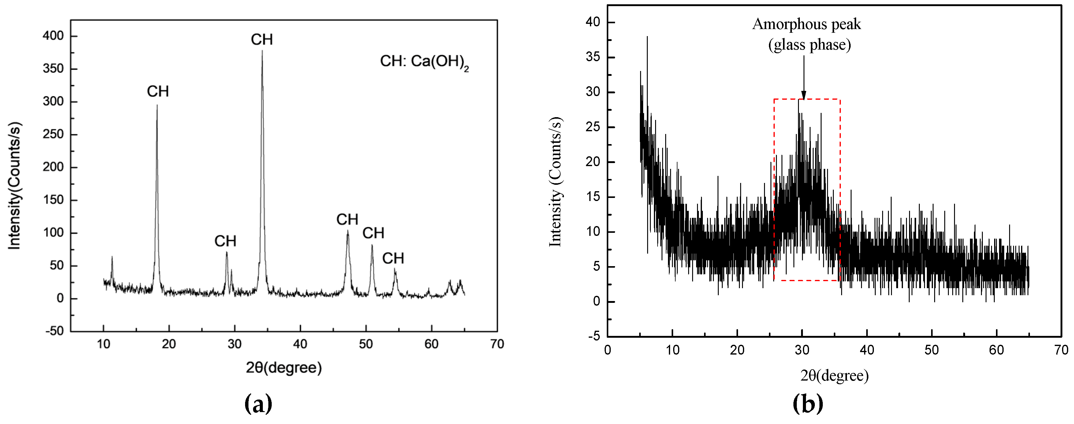
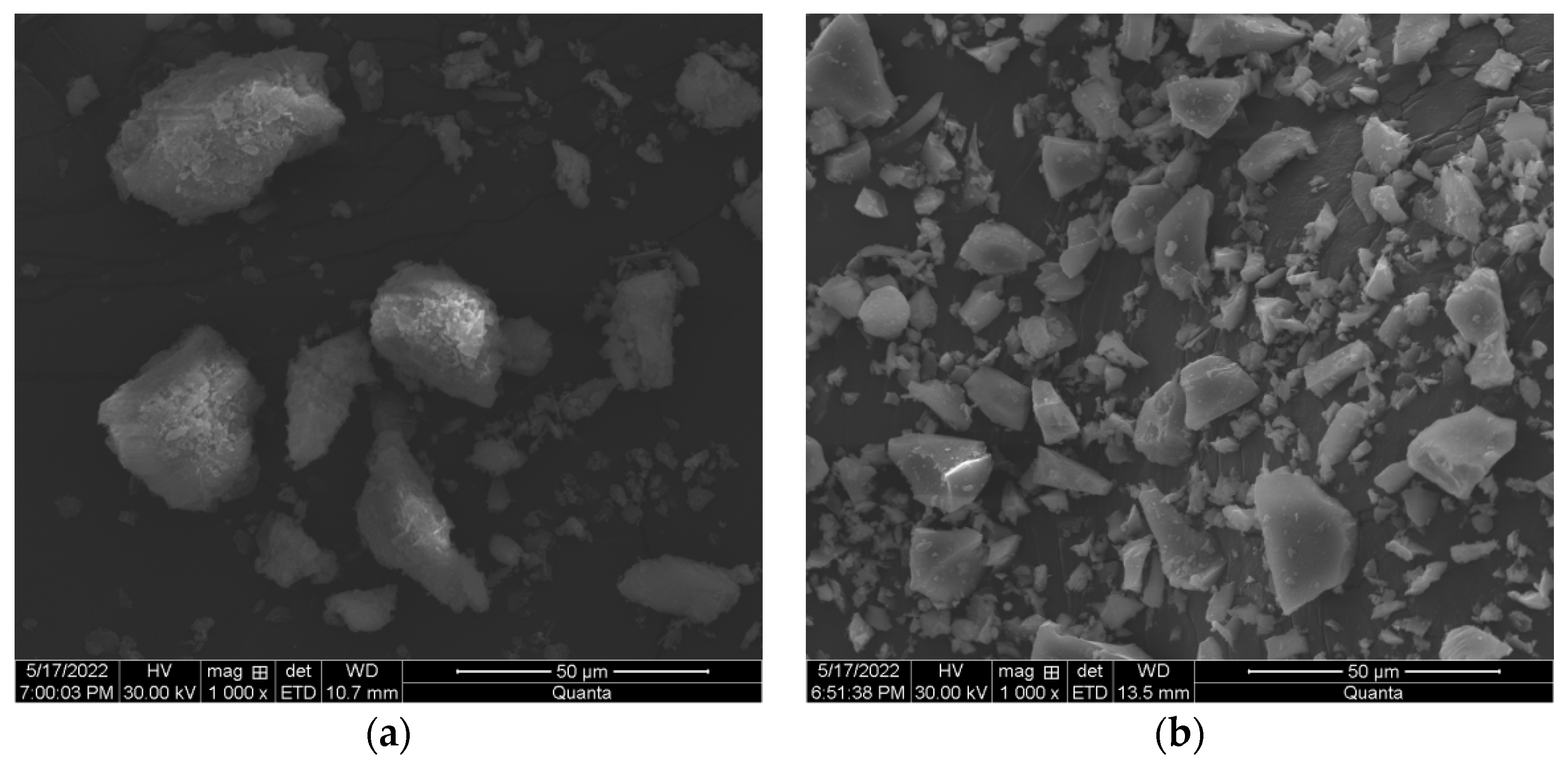
2.1. Materials

The wet carbide slag used in this experiment was provided by Henan Shenma Chlor Alkali Development Co., Ltd., Pingdingshan, China. The powered blast furnace slag (S105) used in this study came from Gongyi Longze Water Purification Materials Co., Ltd. (Zhengzhou, China) with a bulk density of 488 kg/m3. Their chemical composition, mineralogical property and morphology were determined by X-ray fluorescence (XRF), X-ray diffraction analysis (XRD) and scanning electron microscopy (SEM). The chemical composition of carbide slag was shown in Table 1, and its main component of CaO was 90.29%. Figure 1a showed the X-ray diffraction analysis of carbide slag, and the peaks at 2θ = 18.2°, 34.2°, and 47.2° were typical for Ca(OH)2 (CH). The morphology of carbide slag is shown in Figure 2a. It displayed irregularity, and the particle size was approximately between 5 and 45 μm through measurement. The chemical composition, X-ray diffraction analysis and morphology of blast furnace slag are shown in Table 2, Figure 1b and Figure 2b, respectively. The main components of blast furnace slag were CaO, SiO2 and Al2O3. The XRD analysis of blast furnace slag showed an obvious dispersion peak in the range of 25–35°, which indicated the presence of a large amount of amorphous peaks (glass phase). The morphology of blast furnace slag presented irregular as well, and the particle size was approximately between 2 and 25 μm. The hydraulic coefficient b, alkalinity coefficient M0, activity coefficient M1 and mass coefficient K of blast furnace slag were calculated via Equations (1)–(4), which indicated blast furnace slag had high hydration activity. Sodium hydroxide were analytical reagents and purchased from Yantai Shuangshuang Chemical Co., Ltd., Yantai, China.
b = C a O + A l 2 O 3 + S i O 2 S i O 2 = 42.21 + 15.62 + 27.24 27.24 = 3.12
M 0 = W C a O + W M g O W S i O 2 + W A l 2 O 3 = 42.21 + 9.01 27.24 + 15.62 = 1.20
M 1 = W A l 2 O 3 W S i O 2 = 15.62 27.24 = 0.57
K = W C a O + W M g O + W A l 2 O 3 W S i O 2 + W M n O + W T i O 2 = 42.21 + 9.01 + 15.62 27.24 + 0.47 + 1.22 = 2.31

2.2. Mixture Proportions

Details of carbide slag and alkali-activated blast furnace slag paste (CAB) mixtures tested in this study are presented in Table 3, Table 4 and Table 5. In all CAB mixtures, the spread flow was kept constant at (120 ± 5) mm. The carbide slag for each CAB mixture was dried in an electric oven and ground in a laboratory steel ball mill. The alkaline activator for each CAB mixture was prepared by dissolving an alkaline compound into tap water before mixing. The effects of the carbide slag to blast furnace slag paste ratio, alkali activator, and curing conditions were investigated by varying design factors.
M1, M7 and M15 were designed as the reference CAB paste. The interaction between carbide slag and blast furnace slag in CAB pastes was studied by using different combinations of carbide slag and blast furnace slag in M1 to M6. M7 to M14 were designed to study the effect of elevating sodium hydroxide activator (NaOH), and M15 to M17 were designed to study the effect of curing conditions. The standard curing was at 20 °C and 95% relative humidity, the sample was put into water for curing. The steam curing was autoclaved at 120 °C for 8 h and then cured under standard conditions.

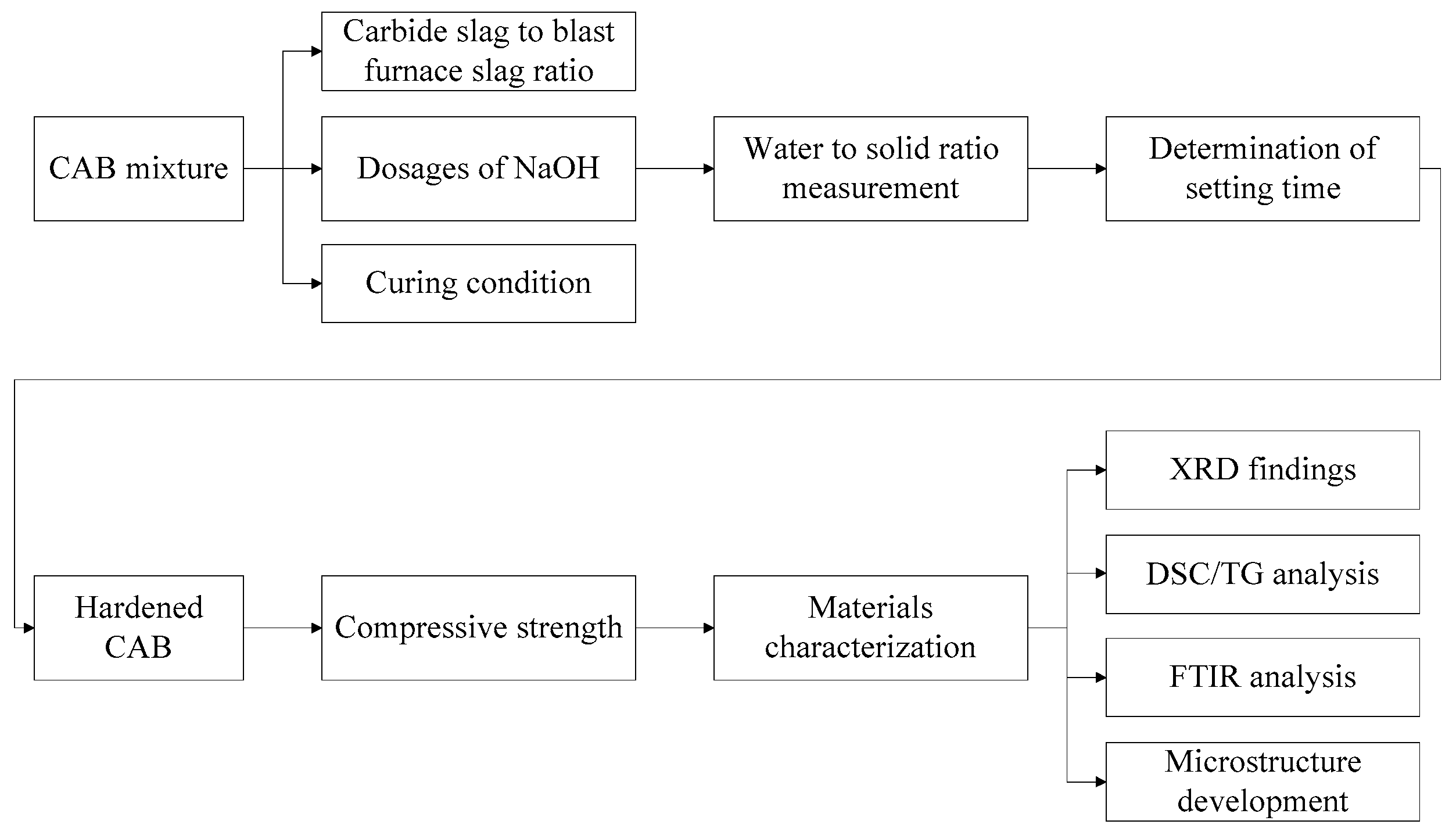
2.3. Experimental Method (Sample Preparation) (Figure 3)

(1)
Water-to-Solid Ratio Test
The water-to-solid ratio of the CAB pastes was measured using a slump test according to GB/T 8077-2012 <Methods for testing uniformity of concrete admixture> [41]. The test procedure as follows: the glass plate, truncated cone round mold, agitator and stirring pot were wiped to make their surfaces wet without water stains. The glass plate was put in a horizontal position, and the truncated cone round mold (height 60 mm, top diameter 36 mm and bottom diameter 60 mm) was placed in the center of the glass plate. Then, 300 g of CAB mixture was weighed and added to the mixing water, which dissolved alkaline. This was followed by stirring for 4 min. Next, the paste was transferred into a truncated cone round mold placed on a glass plate and then vertically lifted. The resulting spread of paste was measured twice, the second measurement being perpendicular to the first. The final spread flow value was taken as the average of the two value measured. At last, the final water to solid ratio yielding a spread flow of (120 ± 5) mm was achieved.
(2)
Determination of Setting Time
The setting time was tested according to GB/T 1346-2011 <Test method for water requirement of normal consistency, setting time and soundness of the Portland cement> [42]. Briefly, 500 g of CAB mixture was slowly added to the measured water, which dissolved alkaline. The suspension was mixed for 4 min to form a homogenous paste, and then the paste was cast into pieces (height 40 mm, top diameter 65 mm and bottom diameter 75 mm). The entrained air was removed by tapping the slurry beyond the test mold 5 times using a right angle knife. Excess paste was sawed off gently at about 1/3 of the upper surface of the test mold. When the test needle sank to (4 ± 1) mm from the bottom plate, the paste reached the initial setting state. When the test needle sank 0.5 mm into the test body, the paste reached the final setting state.
(3)
Compressive Strength
The compressive strength was measured according to GB/T 17671-2021 <Test method of cement mortar strength (ISO method)> [43]. Six replicate specimens (40 mm × 40 mm × 80 mm) were prepared for each condition (time and dosage) to obtain the average and variability in compressive strength test results. Briefly, 1 kg of CAB mixture was slowly added to the measured water. The suspension was mixed for 4 min to form a homogenous paste, and then the pastes were filled into molds. The entrained air was removed by lifting the mold by approximately 1 cm and subsequent dropped. This procedure was repeated 5 times. Excess paste was removed by scratching the surface with a ruler. After 1 days, the molds was dismantled, compressive strength was measured after 3 days, 7 days, 14 days and 28 days.
Figure 3. Photos during testing of water to solid ratio, setting time, and compressive strength: (a) water to solid ratio; (b) setting time; (c) compressive strength.
Buildings 14 01681 g003

2.4. Materials Characterization

After the test specimens were cured for the corresponding time under specified conditions, hydration was terminated with absolute ethanol, and the specimens were dried in a vacuum drying oven at 45 °C for 24 h, followed by XRD, DSC/TG, FTIR and SEM analysis.
After the hydration of CAB pastes, CAB paste samples of various ages were ground into fine powder for analysis. The resulting reaction product assemblage was characterized by XRD. The measurements were made using a X’ Pert pro diffractometer equipped with a CoKα X-ray tube operated at 40 kV voltage and 40 mA with step of 0.02° (2θ) and scanning time of 30 s/°. The CAB paste samples were scanned between 5° and 65° (2θ).
The characteristic functional groups of the phases present in CAB paste samples were studied using a ThermoFisher Nicolet FT-IR spectrometer. The background spectrum was collected using a pure KBr pellet, and the infrared Fourier transform spectroscopy enabled measurement of the range between 4000 and 400 cm−1.
A simultaneous differential scanning calorimetry/thermogravimetric analysis was carried out by Netzsch STA 449 F3 Jupiter under nitrogen atmosphere. Approximately 10 mg of the samples was heated from room temperature to 1000 °C with a heating rate of 10 °C/min in an Al2O3 crucible with an identical crucible as reference.
The morphological investigations of hydration products were observed by scanning electron microscopy (QUANTA 450). The pieces were coated with a Au-Pd layer to improve conductivity and image quality before the test.

2.5. Experimental Techniques

Figure 4 exhibits the process flow diagram.

3. Results and Discussion

3.1. Properties

3.1.1. Effect of Carbide Slag to Blast Furnace Slag Ratio on Properties of CAB Pastes

The water-to-solid ratio, setting time and compressive strength of the CAB pastes were measured (Figure 5). Figure 5a showed the water-to-solid ratio increased slightly with a different carbide slag to blast furnace slag ratio when the slump flow of CAB pastes was fixed at (120 ± 5) mm by adjusting the water content. In Figure 5b, it can be seen that there was a small increase trend in the setting time for CAB pastes. At the carbide slag to blast furnace slag ratio of 0:100, the initial setting time was 63 min, and its final was 31 min longer than the initial. The initial and final setting times increased steadily to 75 min and 105 min when the carbide slag to blast furnace slag ratio was 30: 70. This can be due to the decrease of blast furnace slag, and the excitation effect of carbide slag was far weaker than that of sodium hydroxide.
Measurements of compressive strength hydrated for 3 days, 7 days, 14 days and 28 days were shown in Figure 5c. Clearly, the compressive strength of CAB pastes decreased with increasing carbide slag substitution ratio and increased with longer curing time. At 3 days, the compressive strength of the M1, M2, M3, M4, M5, and M6 mixes was 19.8 MPa, 19.5 MPa, 19.0 MPa, 17.9 MPa, 16.5 MPa, and 15.5 MPa, respectively. After 7 days, the compressive strength of the M1, M2, M3, M4, M5, and M6 mixes improved by 39.9%, 40.5%, 41.6%, 44.1%, 31.5%, and 6.5%, respectively. At 14 days, the improvement in the compressive strengths of the M1, M2, M3, M4, M5, and M6 mixes was 58.6%, 58.5%, 60.5%, 67.6%, 66.7%, and 33.5%, respectively. After 28 days curing, the M1, M2, M3, M4, M5, and M6 mixes outperformed the 3-day mix by 70.7%, 69.7%, 65.3%, 71.5%, 84.9%, and 56.8%, respectively. It was noteworthy that the compressive strength of M1–M6 decreased with increasing carbide slag substitution ratio at the same curing time. Note that the greatest compressive strength appeared in the CAB pastes with the lowest carbide slag content. The highest compressive strength (1–28 days) occurred in M1, and its compressive strength was 19.8 MPa at 3 days, 27.7 MPa at 7 days, 31.4 MPa at 14 days, and 33.8 MPa at 28 days. At the curing time of 3 days, the M2, M3, M4, M5, and M6 mixes underperformed the control mix by 1.5%, 4.0%, 9.6%, 16.7%, and 21.7%, respectively. At 7 days, the M2, M3, M4, M5, and M6 mixes exhibited a lag of 1.1%, 2.9%, 6.9%, 21.7%, and 40.43%, respectively, compared to the control mix. At 14 days, the compressive strength of M2, M3, M4, M5, and M6 mixes showed a lag of 1.6%, 2.9%, 4.5%, 12.4%, and 31.4%, respectively, compared with the control mix. After 28 days, the compressive strength of M2, M3, M4, M5, and M6 mixes decreased by 2.1%, 7.1%, 9.2%, 9.8%, and 28.1%, respectively. Therefore, the compressive strength of CAB pastes decreased with the increase of carbide slag. This observation was in agreement with the discovery of Seo et al. [39], who deemed that the compressive strength of the mixtures of carbide slag and blast furnace slag linearly diminished as the amount of carbide slag increased.

3.1.2. Effect of NaOH on Properties of CAB Pastes

The water-to-solid ratio, setting time and compressive strength of the CAB pastes with increasing NaOH were measured (Figure 6). Figure 6a shows that the water-to-solid ratio decreased slightly as the dosage of NaOH increased. It decreased to 0.49 at the dosage of 4% and then further decreased to 0.45 at the dosage of 10%. In Figure 6b, it could be observed that there was an decreasing trend in the setting time for CAB pastes. The initial and final setting time of M7 was 89 min and 119 min, and it decreased dramatically to 53 min and 89 min at the dosage of 5%. At last, it decreased again but more steeply to 27 min and 68 min.
The compressive strength development of CAB pastes after adding NaOH was reported in Figure 6c. The influence of NaOH on the strength of CAB pastes showed a trend of increasing first and then decreasing, and the effects of different NaOH content on the strength results were close to each other from 3 days to 28 days. The compressive strength of M12 after 3 days and 7 days of curing tended to level off (24.8 MPa and 36.3 MPa) compared to the others, and the compressive strength of M11 after 14 days and 28 days of curing tended to level off (43.3 MPa and 44.5 MPa) relative to the others. The highest compressive strength at 3 days and 7 days was achieved for M12, indicating that the optimum NaOH content was 6 wt% in terms of strength performance at 3 days and 7 days. In addition, the highest compressive strength at 14 days and 28 days was achieved for M11, indicating that the optimum NaOH content was 5 wt% in terms of the strength performance at 14 days and 28 days.

3.1.3. Effect of Curing Conditions on Properties of CAB Pastes

The compressive strength of the CAB pastes under different curing conditions was measured in Figure 7. Clearly, the compressive strength can be observed to increase with time under standard curing condition and water curing condition. At standard curing condition, the compressive strength of 19.0 MPa was obtained at 3 days, and this increased by 51.6%, 60.5% and 65.3% at 7 days, 14 days and 28 days, respectively. At water curing condition, the compressive strength of 23.3 MPa was gained at 3 days, and this increased by 16.3%, 24.0%, and 36.9% at 7 days, 14 days and 28 days, respectively. However, the compressive strength of 25.8 MPa was gained at 3 days, and this increased by 7.0% and 15.1% as the time increased from 7 days to 14 days when curing at steam condition. The curing time in the excess of 14 days resulted in the negative trend in terms of strength development. In addition, the compressive strengths of 25.8 MPa at 3 days and 27.6 MPa at 7 days of M17 were observed, which were higher than M15 and M16 at the same curing time. This value was close to the compressive strength at 14 days under the standard curing condition and water curing condition, and it decreased to 28.2 MPa at 28 days. This indicated that the steam curing condition enhanced early strength development, and it was not conductive to the later strength development. Furthermore, the compressive strengths of 23.3 MPa at 3 days and 27.1 MPa at 7 days of M16 were observed to be higher than M15, and this number was close to each other at after 14 days and 28 days of curing time. This meant that the water curing condition enhanced early strength development as well and contributed to the later strength. Thus, it could be concluded that the water curing condition was suitable for the development of compressive strength. Compared with the previous similar study on fly ash geopolymer activated by carbide slag, the compressive strengths of CAB pastes were significantly high at 3 days, 7 days and 28 days [44].

3.2. Reaction Products
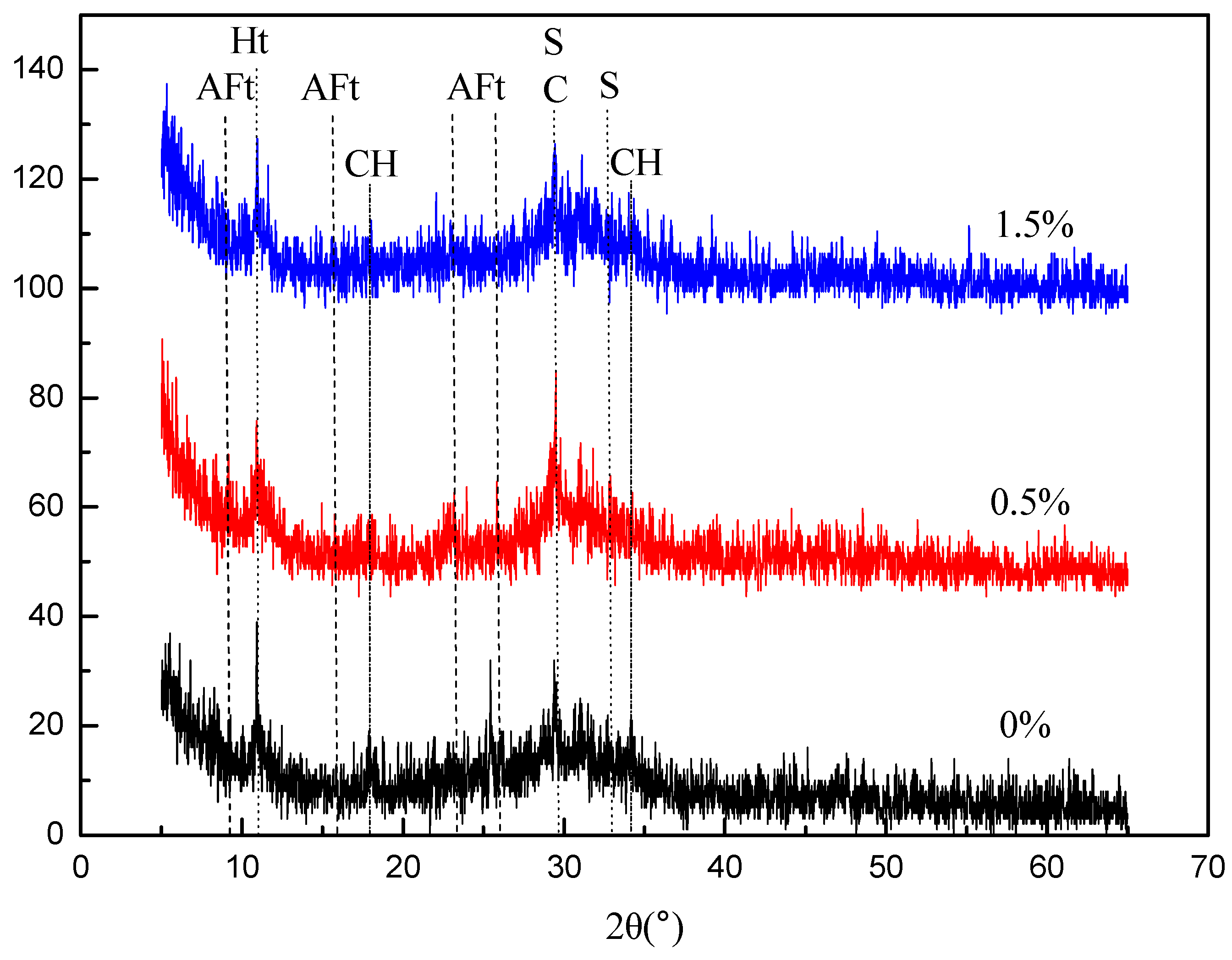
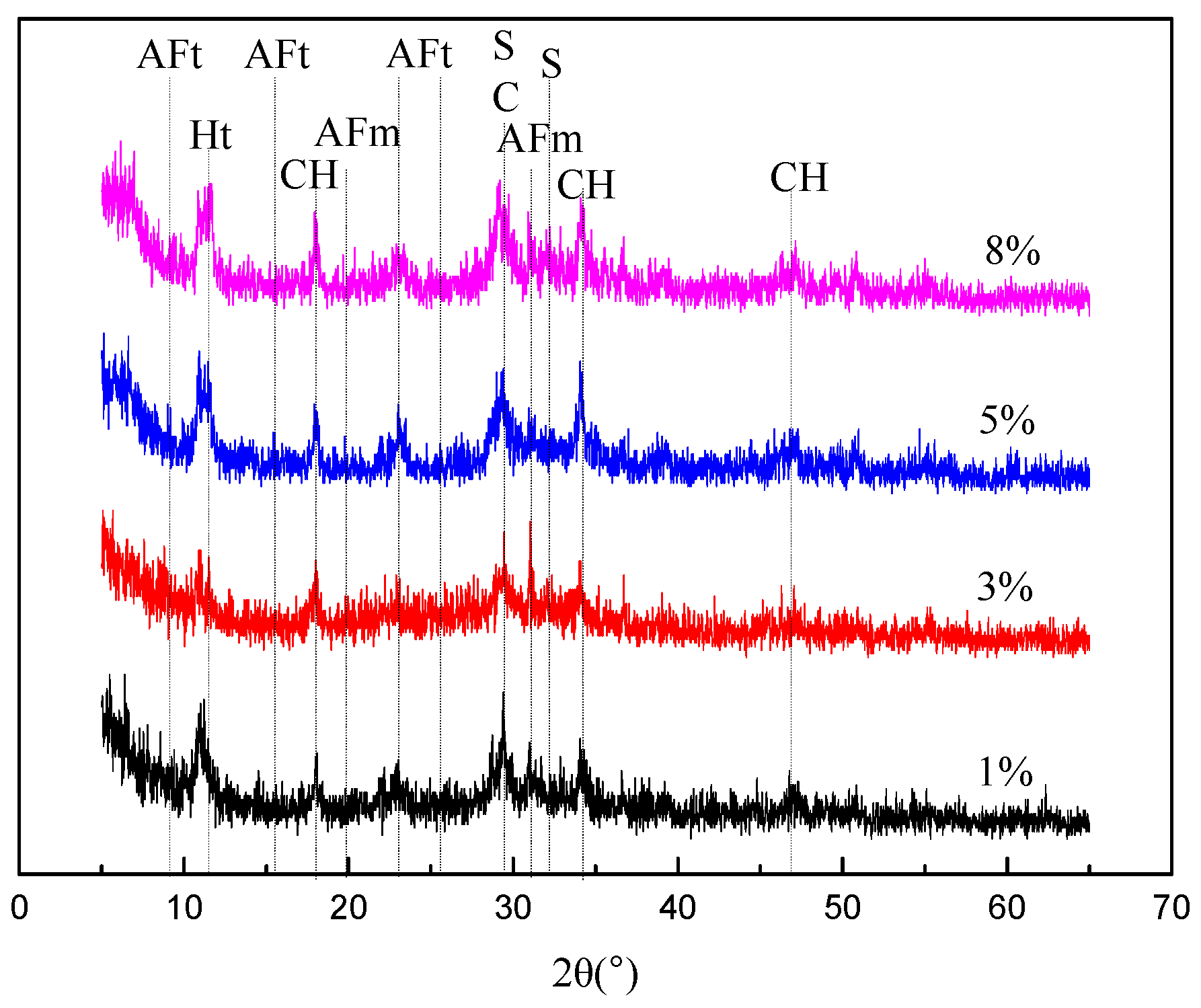
3.2.1. XRD Findings

Based on the study of Li et al. [15], after adding blast furnace slag and carbide slag into water, the blast furnace slag released Ca2+, and the Ca2+ and OH of carbide slag was substantially dissolved into solution. The increased alkalinity in the solution disrupted Si-O-Si, Si-O-Al and other bonds, and it promoted the reaction of the decomposed glass phase into hydration products. When the NaOH was added into the solution, the increased content of OH in the solution increased the alkalinity and accelerated the reaction of carbide slag and blast furnace slag.
The results of the XRD analysis of hardened paste samples with different carbide slag to blast furnace slag ratios obtained at the curing stages of 28 days are shown in Figure 8. In all samples, the main reaction products were calcium silicate hydrate gel (C-S-H, PDF# 00-33-0306), monosulfoaluminate (AFm, PDF# 01-083-1289), ettringite (AFt, PDF# 00-041-1451), and hydrotalcite-like phase (Ht, PDF# 00-014-0191). Adding carbide slag produced calcium hydroxide (CH, PDF# 01-081-2040) and calcite (C, PDF# 01-086-2340). These were the same as the hydration products discovered by Seo et al. using XRD [39]. However, no calcium hydroxide and calcite was found in M1. The profile peak intensities of samples were compared to assess approximately the relative quantities of reaction products. To our surprise, the C-S-H gel located at ~29° and ~32° (2θ) decreased with the increase of carbide slag, and the peaks of calcite and C-S-H gel were both detected at ~29°. Thus, it could be deduced that the addition of carbide slag reduced the content of C-S-H gel. The formation of AFt and AFm is made possible through the presence of soluble sulfate (gypsum) within the blast furnace slag. The intensity of the AFt phase was also diminished in the M3 and M5 mixture. This phenomenon was also found by Seo [39], who thought the intensity of AFt decreased as the amount of carbide slag increased. The C-S-H gel and AFt are the main source of strength development for samples. However, note that strong AFm peaks were produced in the XRD pattern of M3 and M5, which showed that carbide slag promoted the formation of AFm and thus inhibited the formation of AFt, which was indicative of the low strength of M3 and M5. Furthermore, there was a slight peak at 11.6° (2θ) in M1, indicating a hydrotalcite-like phase. This phase has been detected more obviously in mixtures with the addition of carbide slag. This situation was consistent with the findings of Seo [39], who considered that the peak intensity of carbide slag increased as the carbide slag content increased. It indicated that carbide slag promoted the formation of the hydrotalcite-like phase. Concerning the reaction degree of carbide slag, calcium hydroxide and calcite were identified for M3 and M5, and the intensity of the calcium hydroxide and calcite increased with the increase of carbide slag. This meant that the carbide slag was not fully involved in the reaction. These results match well with those of the mechanical strength. Thus, the compressive strength of M3 and M5 decreased.
The XRD patterns of hardened paste samples with different NaOH dosages obtained at the curing stages of 28 days are shown in Figure 9. Similar to the different carbide slag to blast furnace slag ratio mixtures, the C-S-H gel, AFt, AFm, and hydrotalcite-like phases were the main reaction phases observed with all mixtures, and the characteristic peaks of calcium hydroxide and calcite still existed. The diffraction patterns of calcium hydroxide, calcite and C-S-H gel showed only some differences in intensity under different NaOH dosages. To our surprise, a noticeable difference between these mixtures was that the diffraction patterns of AFt and AFm showed clear differences in intensity. The intensity of AFt was higher in the M11 paste compared to the other samples, while the intensity of AFm was lower than others, indicating that the addition of 5 wt% NaOH promoted the formation of AFt and thus inhibited the formation of AFm, which was indicative of the high strength of M11. Therefore, it could be drawn that the strength of M11 was improved by the high content of AFt.
The results of XRD analysis of hardened paste samples under different curing conditions at the curing stages of 3 days and 28 days are shown in Figure 10. The products of hydration of M15 to M17 were fairly similar; C-S-H gel, AFt and hydrotalcite-like phases were observed with all mixtures. The main difference was that the intensity of C-S-H gel and AFt was higher in the M17 sample compared to the M16 at the curing time of 3 days, which in turn was higher than that of the M15 sample. This indicated that steam curing promoted the production of hydration products and thus improved the compressive strength of M17. As the curing age of the samples increased to 28 days, the intensity of C-S-H gel and AFt in the M15 and M16 increased, which meant that standard curing and water curing promoted the production of hydration products at a later age. The XRD findings were well consistent with the strength development results.

3.2.2. DSC/TG Analysis

DSC/TG analysis provides a more in-depth description of these reaction products. Figure 11 showed the curves of DSC/TG for the control sample and those containing various carbide slag amounts at the age of 28 days. All the samples indicated a similar trend by showing several main weight losses. The endothermic peaks at about 23~230 °C corresponded to the dehydration of C-S-H, AFt and AFm phases [45] and removal of interlayer water of the hydrotalcite-like phase, and these were difficult to distinguish. Two DSC peaks were clearly visible, and the mass losses of M1, M3, and M5 were 5.83%, 6.62%, and 7.62%, respectively, within this temperature range. The M3 and M5 samples displayed a slightly higher weight loss before 230 °C than the control sample. This trend of the result seemed to be similar to that obtained by Rashad et al. [46], who found a larger weight loss before 200 °C of the blast furnace slag sample activated by the addition of 15% limestone powder compared with the control one. The decomposition peak appearing at around 318 °C could be assigned to the dehydroxilation of brucite-like layers of hydrotalcite-like phase, and the mass losses of M1, M3, and M5 in this temperature range were 1.70%, 1.99%, and 2.02%, respectively, showing higher contents of hydrotalcite-like phase were generated in the mixtures with higher carbide slag addition. Furthermore, a clearly increased peak and mass loss of M3 and M5 was observed between 370 and 460 °C for the decarbonation of hydrotalcite-like phase and the decomposition of Ca(OH)2 when increasing the carbide slag content in the mixtures. In addition, the formation of endothermic peaks of M3 and M5 at about 670 °C was due to the decomposition of CaCO3. In this temperature range, no mass losses of M1 were found. The mass losses of M3 and M5 were 0.26% and 0.72%, which demonstrated that M5 had a high content of unreacted Ca(OH)2 and CaCO3 obtained by carbonization. Therefore, it could be concluded that the addition of carbide slag increased the content of hydrotalcite-like phase, Ca(OH)2 and CaCO3 and thus reduced the other hydration products of C-S-H and AFt phases, which was consistent with the finding of the XRD results.

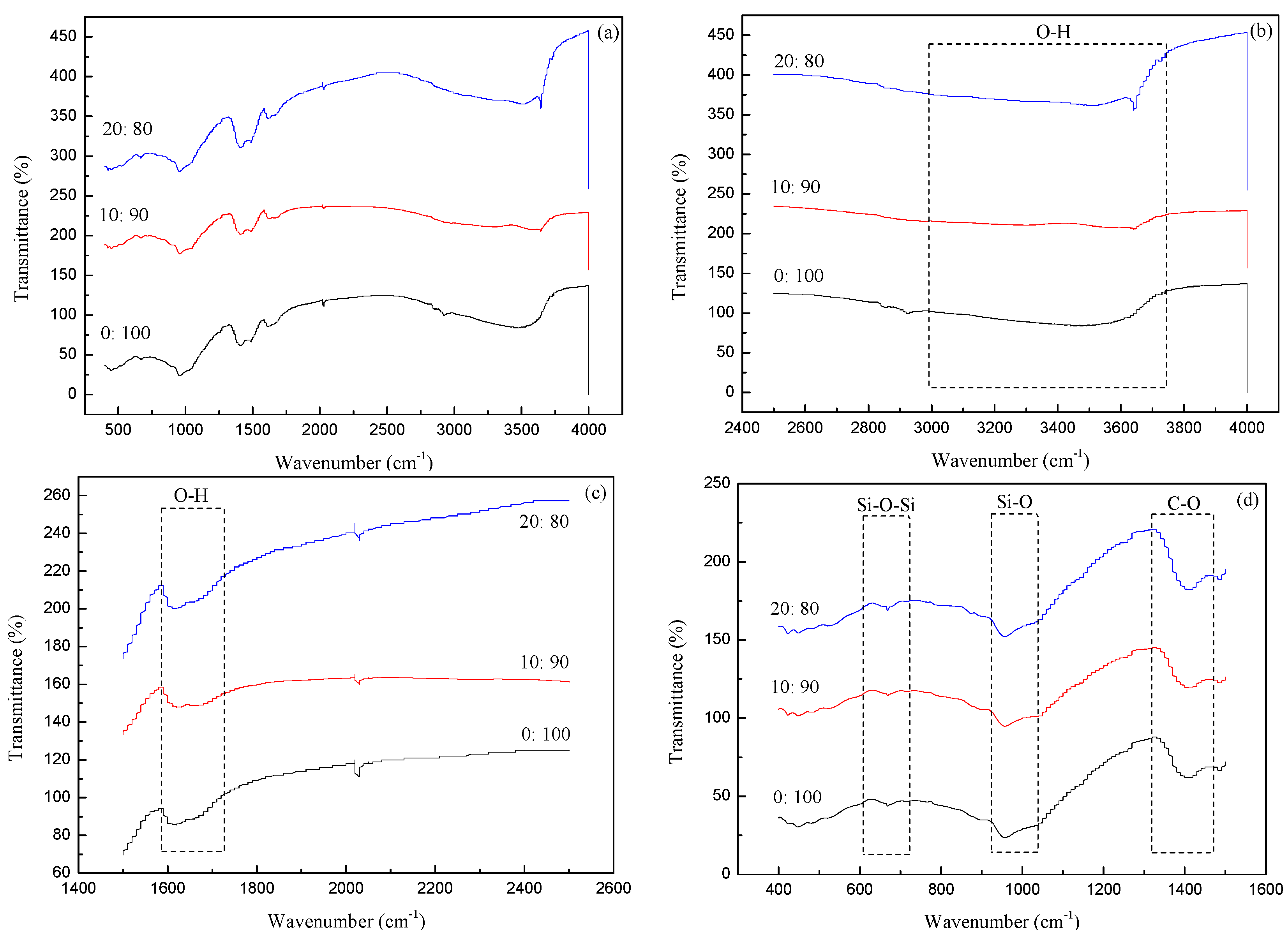
3.2.3. FTIR Analysis

FTIR is powerful in determining the structure of the functional groups that build up the molecules. It enables the characterization of the Si-O, Si-O-Si and O-H bonds, which is useful to track the changes in C-S-H gel and AFt structures as a function of various factors [47,48]. Figure 12 shows the infrared spectra of pastes for the control sample and those containing various carbide slag amounts at the age of 28 days. The band at 957 cm−1 was assigned to the asymmetric stretching vibration of the Si-O bond in C-S-H gels, and the band at 669 cm−1 corresponded to the Si-O-Si bending vibration for C-S-H gels. The variation in these bands with the increase of carbide slag amount from 0% to 20% was not evident as shown in Figure 12d. In addition, the bands located between 3750 and 3000 cm−1 and near 1600 cm−1 were assigned to O-H vibrations, which can provide evidence of the change in AFt [48]. This vibration band between 3750 and 3000 cm−1 was broader in the M1 paste than in the M3 and M5 pastes, and the relative area of band decreased with the increase of carbide slag, indicating the reduction in AFt content, which was in agreement with XRD and DSC/TG.

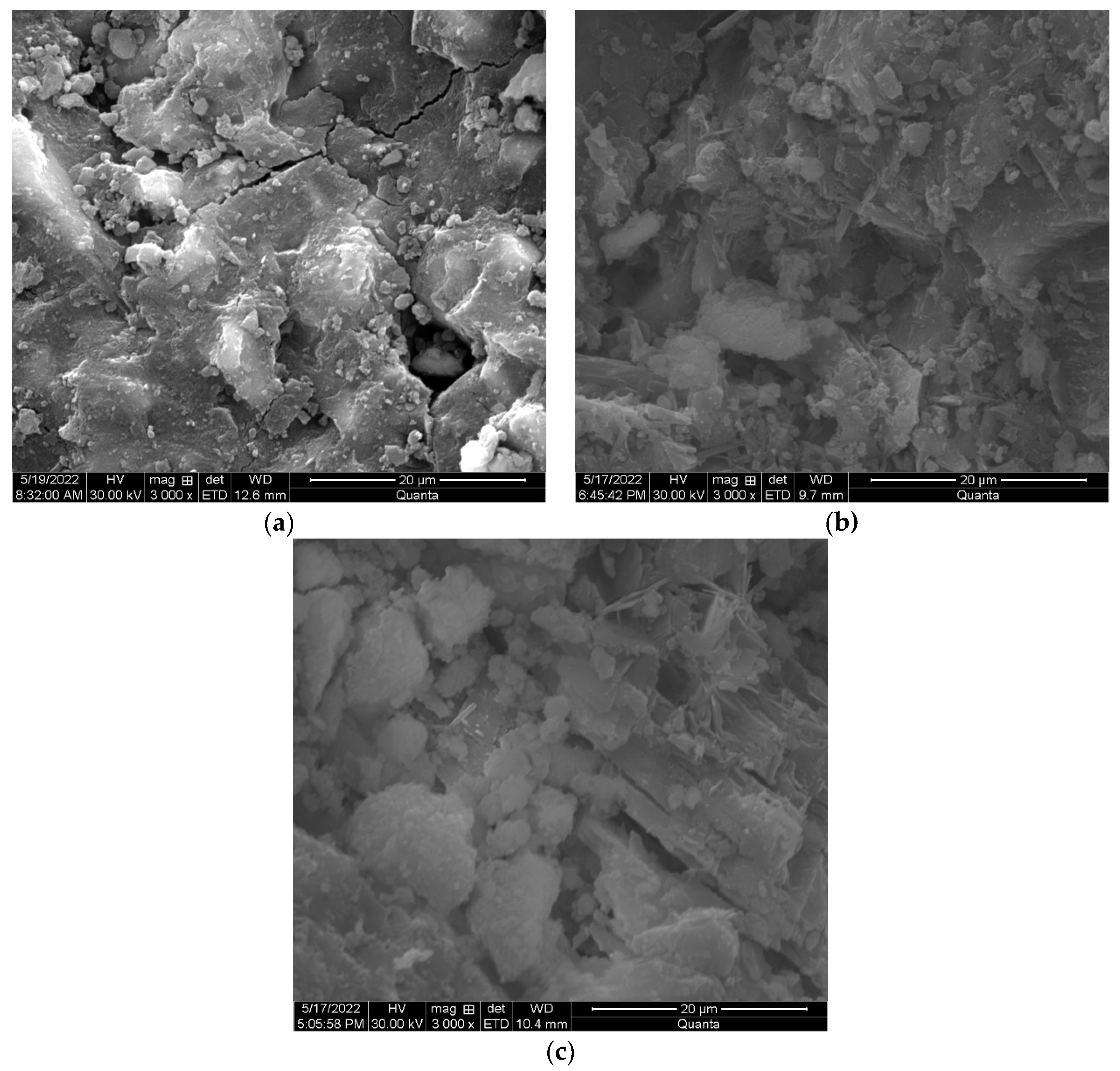
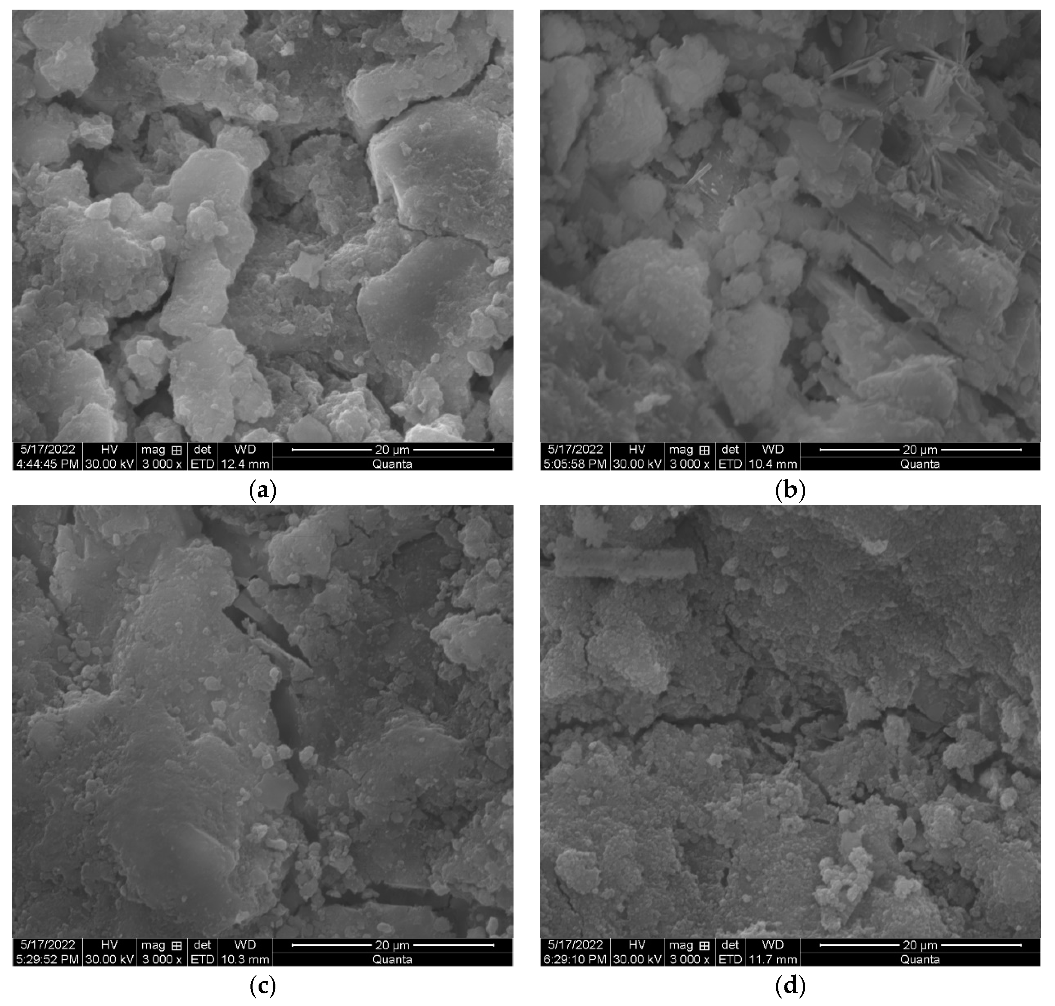
3.3. Microstructure Development

Figure 13 illustrates the representative SEM image of CAB pastes for the control sample and those containing various carbide slag content at the age of 28 days. The mixture of anhydrous materials, hydrated phases and pores was clearly visible. The microstructure of CAB pastes was significantly changed with the increase of carbide slag. The control sample M1 showed a reasonable dense microstructure, which correlated with its good strength. Partially replacing blast furnace slag with 10% carbide slag (M3) resulted in a relatively dense microstructure, and there existed some unreacted carbide slag particles, thus decreasing the compactness of M3. Further increasing the replacement level of blast furnace slag with 20% carbide slag (M5) resulted in a loose and heterogeneous microstructure, and there were more unreacted carbide slag particles present, which could be distinguished by their sharp irregular morphology. As a result, the reduction in compressive strength increased.
The SEM micrographs of CAB pastes containing various NaOH dosage curing for 28 days are presented in Figure 14. There were significant differences in the morphologies with different NaOH dosages. For sample M7, it was apparent that the edges of much of the blast furnace slag and carbide slag particles were still clear, which meant low amounts of hydration products were produced, which explained its relatively low compressive strength. As the dosage of NaOH increased to 3 wt%, the unreacted slag particles became small. In addition, some hydrated products were easily observed in the matrix, suggesting that the increase of NaOH dosage promoted the hydration of blast furnace slag. With the increase of NaOH, hydration products were more obvious and densify. M11 (Figure 14c) showed a much dense microstructure, and no slag particles were observed. This was mainly due to the large amount of AFt. The filling effect of AFt might play a role in reducing the porosity of the matrix, which was related to the high compressive strength of M11. For sample M13, large amounts of unreacted NaOH covered the surface of the hydration products, which was detrimental to the compressive strength.
Figure 15 presents the SEM images of CAB pastes under different curing conditions at the age of 28 days. The morphology of M17 was obviously different from that of M15 and M16. For sample M17, it was clear that the unreacted blast furnace slag and carbide slag were obvious, which explained the decrease of compressive strength at the age of 28 days. For samples M15 and M16, the hydration products increased, and unreacted blast furnace slag and carbide slag were hardly observed in the matrix, indicating a relatively dense microstructure. Therefore, it could be concluded that steam curing was not conductive to the improvement of later strength.

4. Conclusions

In this study, the compressive strength and microstructure of carbide slag and alkali-activated blast furnace slag (CAB) pastes were investigated. The carbide slag to blast furnace slag ratio, alkali activator, and curing conditions have been shown to significantly influence the compressive strength and microstructure of CAB pastes. The following conclusions were drawn. The compressive strength of CAB pastes decreased with increasing carbide slag substitution ratio and increased with longer curing time. After 28-days curing, the M1, M2, M3, M4, M5, and M6 mixes outperformed the 3-days mix by 70.7%, 69.7%, 65.3%, 71.5%, 84.9%, and 56.8%, respectively, and the compressive strength of the M2, M3, M4, M5, and M6 mixes underperformed the control mix M1 by 2.1%, 7.1%, 9.2%, 9.8%, and 28.1%, respectively. Analysis revealed that the addition of carbide slag reduced the content of C-S-H gel, decreased the intensity of the AFt phase, and promoted the formation of hydrotalcite-like phase. Therefore, the compressive strength of CAB pastes decreased with the increase of carbide slag, which was consistent with the findings of Seo et al. The water-to-solid ratio of CAB pastes decreased slightly as the dosage of NaOH increased, and there was also a decreasing trend in the setting time. The water-to-solid ratio decreased to 0.49 at the dosage of 4% and then further decreased to 0.45 at the dosage of 10%. The initial and final setting time of M7 was 89 min and 119 min, and it decreased dramatically to 53 min and 89 min at the dosage of 5%. At last, it decreased again but more steeply to 27 min and 68 min. The development of the strength with NaOH content increased first and then decreased, and it reached the maximum of 24.8 MPa at 3 days and 36.3 MPa at 7 days when the dosage of NaOH was 6%. The maximum compressive strengths of 43.3 MPa at 14 days and 44.5 MPa at 28 days were achieved when the dosage of NaOH was 5%. The high content of AFt was found to be related to the high strength, and its filling effect played a role in reducing the porosity of the matrix. When curing at steam condition, the compressive strength of 25.8 MPa was gained at 3 days, and this increased by 7.0% and 15.1% as the time increased from 7 days to 14 days, and then it decreased to 28.2 MPa at 28 days. Thus, it could be concluded that the steam curing enhanced the early strength development of CAB pastes due to the high intensity of C-S-H gel and AFt produced, but it was not conductive to the later strength development. The water curing enhanced early strength development and contributed to the later strength as well. The compressive strength of 23.3 MPa was gained at 3 days, and this increased by 16.3%, 24.0%, and 36.9% at 7 days, 14 days, and 28 days, respectively. The standard curing was beneficial for later strength but it was not unfavorable for the early strength development. The compressive strength of 19.0 MPa was obtained at 3 days, and this increased by 51.6%, 60.5%, and 65.3% at 7 days, 14 days and 28 days, respectively. Thus, the water curing was suitable for the strength development of CAB pastes. The compressive strengths of CAB pastes were significantly high at 3 days, 7 days and 28 days relative to the previous similar study on fly ash geopolymer activated by carbide slag.

Author Contributions

Methodology, Z.L. and J.W.; Formal analysis, Z.L.; Investigation, N.S., K.X. (Kaiwang Xue), L.X., Y.R., Z.Y. and T.S.; Writing—original draft, K.X. (Kaidong Xu); Writing—review & editing, Z.L.; Project administration, Z.L. All authors have read and agreed to the published version of the manuscript.

Funding

This work was supported by the National College Student Innovation and Entrepreneurship Training Program Project (202311765011); Program of Science and Technology Development of Henan (232102320075, 222102320167).

Data Availability Statement

The original contributions presented in the study are included in the article, further inquiries can be directed to the corresponding authors.

Conflicts of Interest

The authors declare no conflict of interest.

References

  1. Pu, X.; Yao, J.; Zheng, R. Forecast of Energy Consumption and Carbon Emissions in China’s Building Sector to 2060. Energies 2022, 15, 4950. [Google Scholar] [CrossRef]
  2. Wang, J.; Wang, Z.; Peng, S.; Li, C.; Wei, L. Tracing CO2 emissions of China’s construction sector. J. Clean. Prod. 2020, 275, 124165. [Google Scholar] [CrossRef]
  3. Cheng, M.; Lu, Y.; Zhu, H.; Xiao, J. Measuring CO2 emissions performance of China’s construction industry: A global Malmquist index analysis. Environ. Impact Assess. Rev. 2022, 92, 106673. [Google Scholar] [CrossRef]
  4. Hu, S. The cement industry has great achievements in the national “double carbon” strategy. China Cem. 2022, 4, 32–33. [Google Scholar]
  5. Shi, C.; Qu, B.; Provis, J.L. Recent progress in low-carbon binders. Cem. Concr. Res. 2019, 122, 227–250. [Google Scholar] [CrossRef]
  6. Olukotun, N.; Sam, A.R.M.; Lim, N.H.A.S.; Abdulkareem, M.; Mallum, I.; Adebisi, O. Mechanical Properties of Tin Slag Mortar. Recycling 2021, 6, 42. [Google Scholar] [CrossRef]
  7. Ren, B.; Zhao, Y.; Bai, H.; Kang, S.; Zhang, T.; Song, S. Eco-friendly geopolymer prepared from solid wastes: A critical review. Chemosphere 2021, 267, 128900. [Google Scholar] [CrossRef] [PubMed]
  8. Maldonado-Alameda, A.; Mañosa, J.; Giro-Paloma, J.; Formosa, J.; Chimenos, J.M. Alkali-Activated Binders Using Bottom Ash from Waste-to-Energy Plants and Aluminium Recycling Waste. Appl. Sci. 2021, 11, 3840. [Google Scholar] [CrossRef]
  9. Benhamouda, A.; Castro-Gomes, J.; Pereira-De-Oliveira, L. Rheology, Mechanical Properties and Porosity of Ternary Alkali-Activated Binders Based on Mining Mud Waste with Waste Glass and Metakaolin. CivilEng 2021, 2, 236–253. [Google Scholar] [CrossRef]
  10. Zhou, Y.; Sun, J.; Liao, Y. Infuence of ground granulated blast furnace slag on the early hydration and microstructure of alkali activated converter steel slag binder. J. Therm. Anal. Calorim. 2022, 147, 243–252. [Google Scholar] [CrossRef]
  11. Huang, L.; Ye, H. Factors Affecting Kinetics and Gel Composition of Alkali–Silica Reaction in Alkali-Activated Slag Mortars. Int. J. Civ. Eng. 2021, 19, 453–462. [Google Scholar] [CrossRef]
  12. Li, P.; Tang, J.; Bai, Y.; Chen, X.; Chen, J. Experimental study on the pH for activating ground granulated blast-furnace slag activity at different temperatures. Sadhana 2019, 44, 213. [Google Scholar] [CrossRef]
  13. Hruby, P.; Bilek, V.; Topolar, L.; Kalina, L.; Iliushchenko, V.; Koplik, J.; Masilko, J.; Soukal, F. Resistance of alkali-activated blast furnace slag to acids. J. Physics Conf. Ser. 2021, 2341, 012002. [Google Scholar] [CrossRef]
  14. Usherov-Marshak, A.; Vaičiukynienė, D.; Krivenko, P.; Bumanis, G. Calorimetric Studies of Alkali-Activated Blast-Furnace Slag Cements at Early Hydration Processes in the Temperature Range of 20–80 °C. Materials 2021, 14, 5872. [Google Scholar] [CrossRef] [PubMed]
  15. Li, M.; Tan, H.; Zhang, J.; Deng, X.; Kong, X.; Chen, P.; Jian, S.; He, X.; Yang, J. Enhancement in compressive strength of carbide slag activated ground granulated blast furnace slag by introducing CaCl2 and NaCl. Constr. Build. Mater. 2023, 385, 131071. [Google Scholar] [CrossRef]
  16. Lin, Y.; Xu, D.; Ji, W.; Zhao, X. Experiment on the Properties of Soda Residue-Activated Ground Granulated Blast Furnace Slag Mortars with Different Activators. Materials 2022, 15, 3578. [Google Scholar] [CrossRef] [PubMed]
  17. Laurent, S.; Simon, B.; Laurent, F.; Patapy, C. Experimental evidence for the acceleration of slag hydration in blended cements by the addition of CaCl2. Cem. Concr. Res. 2022, 149, 106558. [Google Scholar]
  18. Karam, R.; Paris, M.; Deneele, D.; Wattez, T.; Cyr, M.; Bulteel, D. Effect of sediment incorporation on the reactivity of alkali-activated GGBFS systems. Mater. Struct. 2021, 54, 18. [Google Scholar] [CrossRef]
  19. Klimenko, N.N.; Mikhailenko, N.Y.; Delitsin, L.M.; Sigaev, V.N. Effect of Particle Size of Quartz Sand Filler on Microstructure and Strength of Alkali-Activated Slag-Based Materials. Arab. J. Sci. Eng. 2021, 46, 4337–4352. [Google Scholar] [CrossRef]
  20. Bilici, S.; Kabay, N.; Miyan, N.; Omur, T.; Ozkan, H. Effect of washing aggregate sludge waste on the properties of alkali-activated blast furnace slag. J. Build. Eng. 2023, 63, 105527. [Google Scholar] [CrossRef]
  21. Occhicone, A.; Vukčević, M.; Bosković, I.; Ferone, C. Red Mud-Blast Furnace Slag-Based Alkali-Activated Materials. Sustainability 2021, 13, 11298. [Google Scholar] [CrossRef]
  22. Niu, H.; Helser, J.; Corfe, I.J.; Kuva, J.; Butcher, A.R.; Cappuyns, V.; Kinnunen, P.; Illikainen, M. Incorporation of bioleached sulfidic mine tailings in one-part alkali-activated blast furnace slag mortar. Constr. Build. Mater. 2022, 333, 127195. [Google Scholar] [CrossRef]
  23. Zhao, Y.; Shi, T.; Cao, L.; Kan, L.; Wu, M. Influence of steel slag on the properties of alkali-activated fly ash and blast-furnace slag based fiber reinforced composites. Cem. Concr. Compos. 2021, 116, 103875. [Google Scholar] [CrossRef]
  24. Feng, S.; Zhu, J.; Wang, R.; Qu, Z.; Song, L.; Wang, H. The Influence of CaO and MgO on the Mechanical Properties of Alkali-Activated Blast Furnace Slag Powder. Materials 2022, 15, 6128. [Google Scholar] [CrossRef]
  25. Huang, Z.; Wang, Q.; Lu, J. The effects of cations and concentration on reaction mechanism of alkali-activated blast furnace ferronickel slag. Compos. Part B Eng. 2022, 236, 109825. [Google Scholar] [CrossRef]
  26. Zhang, Z.; Xie, C.; Sang, Z.; Li, D. Mechanical Properties and Microstructure of Alkali-Activated Soda Residue-Blast Furnace Slag Composite Binder. Sustainability 2022, 14, 11751. [Google Scholar] [CrossRef]
  27. Wu, Y.; Jia, Z.; Qi, X.; Wang, W.; Guo, S. Alkali-activated materials without commercial activators: A review. J. Mater. Sci. 2024, 59, 3780–3808. [Google Scholar] [CrossRef]
  28. Najimi, M.; Ghafoori, N.; Sharbaf, M. Alkali-activated natural pozzolan/slag binders: Limitations and remediation. Mag. Concr. Res. 2019, 72, 919–935. [Google Scholar] [CrossRef]
  29. Thomas, S.E.; Ramaswamy, K.; Thomas, B.S. A review on rheological behaviour of alkali activated materials and the influence of composition factors. Mater. Today Proc. 2023. [Google Scholar] [CrossRef]
  30. Kong, Y.; Kurumisawa, K. Fresh properties and characteristic testing methods for alkali-activated materials: A review. J. Build. Eng. 2023, 75, 106830. [Google Scholar] [CrossRef]
  31. Wang, D.; Wang, Q.; Huang, Z. New insights into the early reaction of NaOH-activated slag in the presence of CaSO4. Compos. Part B 2020, 198, 108207. [Google Scholar] [CrossRef]
  32. Kahlouche, R.; Badaoui, A. Mechanical Performance and Durability of Mortar Based on Slag Cement and NaOH-Activated Slag. Mater. Sci. Forum 2022, 1078, 179–188. [Google Scholar] [CrossRef]
  33. Adesanya, E.; Perumal, P.; Luukkonen, T.; Yliniemi, J.; Ohenoja, K.; Kinnunen, P.; Illikainen, M. Opportunities to improve sustainability of alkali-activated materials: A review of side-stream based activators. J. Clean. Prod. 2021, 286, 125558. [Google Scholar] [CrossRef]
  34. Omur, T.; Kabay, N.; Miyan, N.; Özkan, H.; Özkan, Ç. The effect of alkaline activators and sand ratio on the physico-mechanical properties of blast furnace slag based mortars. J. Build. Eng. 2022, 58, 104998. [Google Scholar] [CrossRef]
  35. Alsalman, A.; Assi, L.N.; Kareem, R.S.; Carter, K.; Ziehl, P. Energy and CO2 emission assessments of alkali-activated concrete and Ordinary Portland Cement concrete: A comparative analysis of different grades of concrete. Clean. Environ. Syst. 2021, 3, 100047. [Google Scholar] [CrossRef]
  36. Komkova, A.; Habert, G. Environmental impact assessment of alkali-activated materials: Examining impacts of variability in constituent production processes and transportation. Constr. Build. Mater. 2023, 363, 129032. [Google Scholar] [CrossRef]
  37. Zhang, J.; Zhang, S.; Zhong, M.; Wang, Z.; Qian, G.; Liu, J.; Gong, X. Relationship between pore structure and hydration activity of CaO from carbide slag. Chin. J. Chem. Eng. 2019, 27, 2771–2782. [Google Scholar] [CrossRef]
  38. Zhang, T.; Chu, G.; Lyu, J.; Cao, Y.; Xu, W.; Ma, K.; Song, L.; Yue, H.; Liang, B. CO2 mineralization of carbide slag for the production of light calcium carbonates. Chin. J. Chem. Eng. 2022, 43, 86–98. [Google Scholar] [CrossRef]
  39. Seo, J.; Park, S.; Yoon, H.N.; Jang, J.G.; Kim, S.H.; Lee, H.K. Utilization of Calcium Carbide Residue Using Granulated Blast Furnace Slag. Materials 2019, 12, 3511. [Google Scholar] [CrossRef] [PubMed]
  40. Kalina, L.; Bílek, V.; Hrubý, P.; Iliushchenko, V.; Kalina, M.; Smilek, J. On the action mechanism of lignosulfonate plasticizer in alkali-activated slag-based system. Cem. Concr. Res. 2022, 157, 106822. [Google Scholar] [CrossRef]
  41. GB/T 8077-2012; Methods for Testing Uniformity of Concrete Admixture. China Building Materials Federation: Beijing, China, 2012.
  42. GB/T 1346-2011; Test Method for Water Requirement of Normal Consistency, Setting Time and Soundness of the Portland Cement. China Building Materials Federation: Beijing, China, 2011.
  43. GB/T 17671-2021; Test Method of Cement Mortar Strength (ISO Method). China Building Materials Federation: Beijing, China, 2021.
  44. Yang, J.; Zhang, Q.; He, X.; Su, Y.; Zeng, J.; Xiong, L.; Zeng, L.; Yu, X.; Tan, H. Low-carbon wet-ground fly ash geopolymer activated by single calcium carbide slag. Constr. Build. Mater. 2022, 353, 129084. [Google Scholar] [CrossRef]
  45. Zheng, H. The Preparation and Property Research of One-Part Alkali-Activated Slag; Guangxi University: Nanning, China, 2021. [Google Scholar]
  46. Rashad, A.M.; Morsi, W.M.; Khafaga, S.A. Effect of limestone powder on mechanical strength, durability and drying shrinkage of alkali activated slag pastes. Innov. Infrastruct. Solut. 2021, 6, 127. [Google Scholar] [CrossRef]
  47. Zhang, J.; Shi, C.; Zhang, Z. Effect of Na2O concentration and water/binder ratio on carbonation of alkali-activated slag/fly ash cements. Constr. Build. Mater. 2020, 269, 121258. [Google Scholar] [CrossRef]
  48. Gijbels, K.; Pontikes, Y.; Samyn, P.; Schreurs, S.; Schroeyers, W. Effect of NaOH content on hydration, mineralogy, porosity and strength in alkali/sulfate-activated binders from ground granulated blast furnace slag and phosphogypsum-ScienceDirect. Cem. Concr. Res. 2020, 132, 106054. [Google Scholar] [CrossRef]
Figure 1. (a,b) XRD pattern of carbide slag and blast furnace slag.
Buildings 14 01681 g001
Figure 2. Morphology of carbide slag and blast furnace slag: (a) carbide slag and (b) blast furnace slag.
Buildings 14 01681 g002
Figure 4. The process flow diagram.
Buildings 14 01681 g004
Figure 5. (ac) Effect of carbide slag to blast furnace slag ratio on properties of CAB pastes.
Buildings 14 01681 g005
Figure 6. (ac) Effect of NaOH on properties of CAB pastes.
Buildings 14 01681 g006
Figure 7. Effect of curing conditions on compressive strength of CAB pastes.
Buildings 14 01681 g007
Figure 8. XRD analyses of pastes with different carbide slag to blast furnace slag ratios at the curing age of 28 days. Ht: hydrotalcite-like phase, CH: calcium hydroxide, S: C-(A)-S-H gel, C: calcium carbonate, AFt: ettringite.
Buildings 14 01681 g008
Figure 9. XRD analyses of pastes with different NaOH dosages at the curing age of 28 days. Ht: hydrotalcite-like phase, CH: calcium hydroxide, S: C-S-H gel, C: calcium carbonate, AFt: ettringite, AFm: calcium monosulfoaluminate.
Buildings 14 01681 g009
Figure 10. (a,b) XRD analyses of pastes under different curing conditions at the curing age of 3 days and 28 days. Ht: hydrotalcite-like phase, CH: calcium hydroxide, S: C-S-H gel, C: calcium carbonate, AFt: ettringite, AFm: calcium monosulfoaluminate.
Buildings 14 01681 g010
Figure 11. Exemplary results of DSC/TG analysis of paste (a) without carbide slag; (b) with 10% carbide slag; (c) with 20% carbide slag.
Buildings 14 01681 g011
Figure 12. FTIR analysis of paste: (a) FTIR curves after 28 days of curing; (b) FTIR curves from 4000 to 2500 cm−1; (c) FTIR curves from 2500 to 1500 cm−1; (d) FTIR curves from 1500 to 400 cm−1.
Buildings 14 01681 g012
Figure 13. SEM images of CAB pastes at different carbide slag content: (a) without carbide slag; (b) with 10% carbide slag; (c) with 20% carbide slag.
Buildings 14 01681 g013
Figure 14. SEM images of CAB pastes with different NaOH content: (a) with 1 wt% NaOH; (b) with 3 wt% NaOH; (c) with 5 wt% NaOH; (d) with 8 wt% NaOH.
Buildings 14 01681 g014
Figure 15. SEM images of CAB pastes under different curing conditions: (a) standard curing; (b) water curing; (c) steam curing.
Buildings 14 01681 g015
Table 1. Chemical composition of carbide slag used (%).
Carbide SlagNa2OMgOAl2O3SiO2P2O5SO3ClK2OCaOTiO2V2O5Fe2O3SrO
Chemical Composition0.740.342.214.230.080.780.930.0190.290.050.020.240.08
Table 2. Chemical composition of blast furnace slag used (%).
Blast Furnace SlagNa2OMgOAl2O3SiO2SO3ClK2OCaOTiO2MnOFe2O3SrOY2O3ZrO2
Chemical Composition0.489.0115.6227.242.730.070.4242.211.220.470.400.070.010.06
Table 3. Mixture proportion of CAB pastes (carbide slag to blast furnace slag ratio).
MixBlast Furnace SlagCarbide SlagSodium HydroxideCuring Conditions
M1100%0%3%Standard curing
M295%5%3%Standard curing
M390%10%3%Standard curing
M485%15%3%Standard curing
M580%20%3%Standard curing
M670%30%3%Standard curing
Table 4. Mixture proportion of CAB pastes (NaOH).
MixBlast Furnace SlagCarbide SlagSodium HydroxideCuring Conditions
M780%20%1%Standard curing
M880%20%2%Standard curing
M980%20%3%Standard curing
M1080%20%4%Standard curing
M1180%20%5%Standard curing
M1280%20%6%Standard curing
M1380%20%8%Standard curing
M1480%20%10%Standard curing
Table 5. Mixture proportion of CAB pastes (curing conditions).
MixBlast Furnace SlagCarbide SlagSodium HydroxideCuring Conditions
M1590%10%3%Standard curing
M1690%10%3%Water curing
M1790%10%3%Steam curing
Disclaimer/Publisher’s Note: The statements, opinions and data contained in all publications are solely those of the individual author(s) and contributor(s) and not of MDPI and/or the editor(s). MDPI and/or the editor(s) disclaim responsibility for any injury to people or property resulting from any ideas, methods, instructions or products referred to in the content.

