Article

Modeling Schemes and Performance Comparisons of Unbonded and Partially Bonded Tendon in Post-Tensioned Concrete Beam

1
China Academy of Building Research, Beijing 100013, China
2
China Building Technique Group Co., Ltd., Beijing 100013, China
3
China Academy of Railway Sciences Co., Ltd., Beijing 100081, China
4
School of Civil Engineering, Beijing Jiaotong University, Beijing 100044, China
*
Author to whom correspondence should be addressed.
Buildings 2024, 14(6), 1682; https://doi.org/10.3390/buildings14061682
Submission received: 9 April 2024 / Revised: 27 May 2024 / Accepted: 3 June 2024 / Published: 6 June 2024
(This article belongs to the Section Building Structures)

Abstract

:
The modeling method of unbonded effects is a challenging and hot topic for the structural performance analysis of unbonded and partially bonded post-tensioned concrete beams. The main concerns accounting for the unbonded effects are the longitudinal free-slip behaviors and the vertical deformation compatibility relationship between the unbonded tendon and concrete beam. Three modeling schemes, namely, the beam–truss element model, the slipping cable element model, and the slack spring model, are presented in this paper. These modeling schemes are, for the first time, systematically compared regarding applicability, convenience, and accuracy. Then, these modeling schemes are applied to experimental beams with different tendon layouts and bonding conditions, including external tendons, internal unbonded tendons, and partially bonded tendons. The beam–truss element model and the slipping cable element model are only applicable to the fully bonded and unbonded members, respectively. The slack spring model is recommended as the generally applicable model for analyzing post-tensioned concrete beams with different bonding conditions. Crucial suggestions are put forward as to the zero-length slack spring element, which have the potential to improve the prediction accuracy for tendon stress. In addition, parametrical analysis is conducted to determine the influence of unbonded length on flexural performance. With the increase of unbonded length, the flexural capacity of the beam will decrease, but the self-centering performance can be improved. Interestingly, the effects of unbonded length on the structural deformability are not monotonic, and the reasons for this are clarified.

1. Introduction

The unbonded prestressing tendon has become a popular option for constructing post-tensioned concrete beam due to its significant advantages of facilitating site operation, replaceability, and preferable deformability [1,2]. The main types of unbonded tendons include internal unbonded and externally prestressing tendons [3]. In particular, the unbonded tendon elongation can no longer be calculated based on the plane-section assumption, but is related to the overall deformation of the concrete beam between the anchor points; this is generally called the unbonded phenomenon. The unbonded effects cause quite different structural performance, as compared to bonded members [4,5], which presents challenges for structural analysis and design [6,7].
Over the past few decades, numerous experimental studies have explored the mechanical properties of unbonded prestressed concrete beams [8,9,10,11]. For the uncracked beam, the influence of the unbonded effects on the structural stiffness is small enough to ignore, because the tendon stress increment is tiny [12]. Once the concrete beam cracks, the tendon elongation will significantly develop along with the structural deformation. Notably, the unbonded tendon stress is uniformly distributed along the tendon length rather than stress-concentrated at the crack cross-section, like the bonded members. Therefore, the flexural performance becomes complex to predict, because the tendon stress can not be directly determined [13]. Even though many efforts have been made to propose simplified formulas to predict the flexural capacity and tendon stress increment [14,15,16], significant differences still exist between the predictions and tests. The main reason is the mutual influence between tendon elongation and structural deformation, which is difficult to describe entirely through simple equations.
Recently, more and more new materials and novel structural designs have been applied to improve the construction technology and working performance of unbonded prestressed concrete beams [17,18,19,20,21,22]. Noteworthily, the partially bonded prestressing tendons have received more attention and discussion [23]. Losanno et al. [24] conducted two partially bonded prestressing concrete beam tests to determine the effects of grouting defects on flexural performance. The tests by Hu et al. [25] and Janet et al. [26] showed that the partially bonded tendon can help achieve both a high rotation and ultimate load capacity. These developments involve more complicated mechanical behaviors, requiring the use of finite element model analysis to study their performance. The critical issue is the appropriate modeling method for the unbonded effects [27].
Typically, with the ignored friction, the unbonded tendon stress is equalized within the length between anchorage points. The tendon deforms vertically with the beam but free-slips along the tangent direction. Currently, two kinds of numerical models are usually adopted to analyze the structural performance of unbonded prestressed concrete beams: the solid element model [28,29] and the beam–truss element model [30,31,32,33,34,35]. In the solid element model [28,29], the interactions between tendons and concrete beam are modeled by hard contact and frictionless interaction to consider the unbonded effects. However, it is considerably time-consuming due to the nonlinearity of co-existing materials, geometry, and boundaries. The beam–truss element model [30,31,32,33,34,35] has significant advantages in computational efficiency. In this model, the concrete beam is generally modeled by the beam element, and the simulation of unbonded prestressed tendons is a core issue that needs to be addressed. Some researchers proposed a new element type, the “slipping cable element” model, to simulate the unbonded effects [32,33,34]. They took the unbonded tendon as a whole element to calculate the tendon elongation, stress, and stiffness rather than conventional truss elements that deform independently. However, the slipping cable element can be only used to model the completely unbonded members, and is not applicable to partially bonded members [24]. Moreover, most general finite element software does not include the “slipping cable element”, which can only be analyzed by self-developed procedure. However, modeling in general finite element software using the two-node truss element and connecting it with the beam node by a rigid beam is a process which can only be used for bonded members [36]. Jaiswal proposed an excellent modeling method which involved removing the rigid link between the truss and beam elements in the unbonded region to consider the unbonded effects [30]. He applied this method to the natural frequency analysis of unbonded members in elastic. Nevertheless, this method is also limited as to ultimate behavior analysis, with large deformation due to the ignored vertical deformation compatibility relation between tendon and beam in the unbonded region. Recently, a new model idea has been proposed, one which involves introducing the slack spring into the conventional beam–truss element model to simulate the unbonded effects equivalently [37]; this is called the “slack spring method”. The zero-length element was introduced between the auxiliary node and truss node with rigid axial stiffness and zero tangential stiffness. In this way, the vertical deformation compatibility relation and the tangential unbonded effects can be satisfied simultaneously. However, the “slack spring method” is mainly used for the internal unbonded straight tendon. Still, the applicability validation for different tendon layouts (curved or draped tendon profiles, etc.) and bond conditions (fully or partially unbonded) has not been well studied.
In general, two main issues still need to be clarified for the modeling of unbonded tendons. First, the “slipping cable element” model and the “slack spring” model are widely used schemes for modeling unbonded tendons, but the associated simulation accuracy is still not well compared and discussed. Second, the “slack spring” model is currently only used for the internal unbonded straight tendon; whether it can be popularized for curved or draped tendons, or in fully or partially unbonded conditions, should be studied. To address these two main issues, three analyses are conducted in this paper. First, the modeling schemes, including the beam–truss element, slipping cable element models, and slack spring models, are systematically reviewed and compared for applicability. Second, a detailed theoretical analysis is conducted for the “slack spring” method, and error sources and suggestions for improvement are proposed for the simulation of unbonded tendons with different profiles and bonding conditions. Further, with the suggested slack spring method, the influences of unbonded length on the flexural performance are studied by parameter analysis. Some interesting influence rules for unbonded length as to deformability, carrying capacity, and self-centering performance are concluded.

2. Modeling Schemes for Unbonded and Partially Bonded Tendons

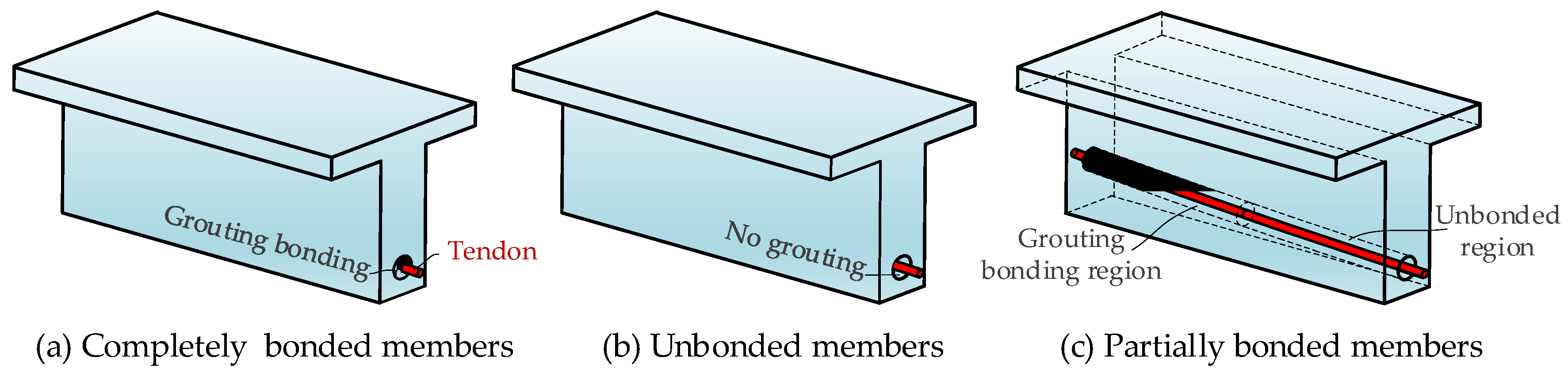
2.1. Mechanical Characteristics of Post-Tensioned Concrete Beams with Different Bonding Conditions

The bonding conditions in post-tensioned concrete beams include completely bonded, unbonded, and partially bonded members, as shown in Figure 1.
For a fully bonded prestressed concrete beam, the grouting in the duct makes the deformation between the tendon and the surrounding concrete compatible, as shown in Figure 1a. The axial and rotational deformation and structural deflection of the concrete beam will cause tendon elongation. The sectional deformation can satisfy the plane-section assumption, showing better bearing capacity and ductility.
For unbonded members (including internally unbonded prestressed members and externally prestressed members), the compatible deformation condition is only satisfied at the anchorage point, as shown in Figure 1b. The tendon’s vertical deformation develops along with the structural deflection in the unbonded area, but there is no connection in the axial direction. Usually, the friction between tendon and concrete is slight, and the free-slip assumption is adopted. In this situation, the tendon stress is equalized between the anchorage points. The tendon elongation depends on the whole structural deformation rather than only sectional analyses like those of bonded members. The modeling method used for the unbonded effects of tendons is a hot topic, and will be further discussed in this paper.
For partially bonded members, the bonded and unbonded areas co-exist in the ducts, as shown in Figure 1c. This situation mainly corresponds to the bonding defects caused by tendon corrosion [24,38] or artificial construction seeking to improve structural performance [25]. The mechanical behaviors of these members are more complicated when considering the bonded and unbonded conditions simultaneously. To the authors’ knowledge, there are still very few studies on modeling methods and performance comparisons for partially bonded concrete beams, topics which will be discussed in this paper.

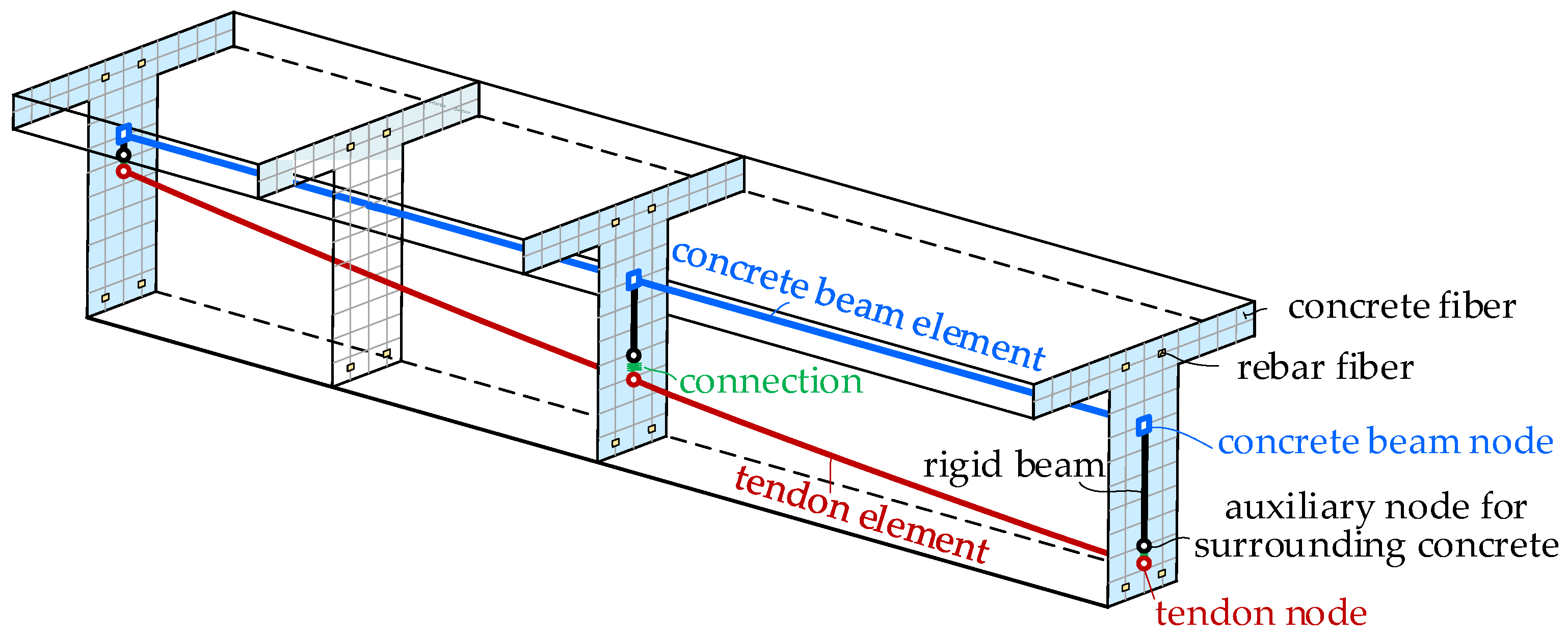
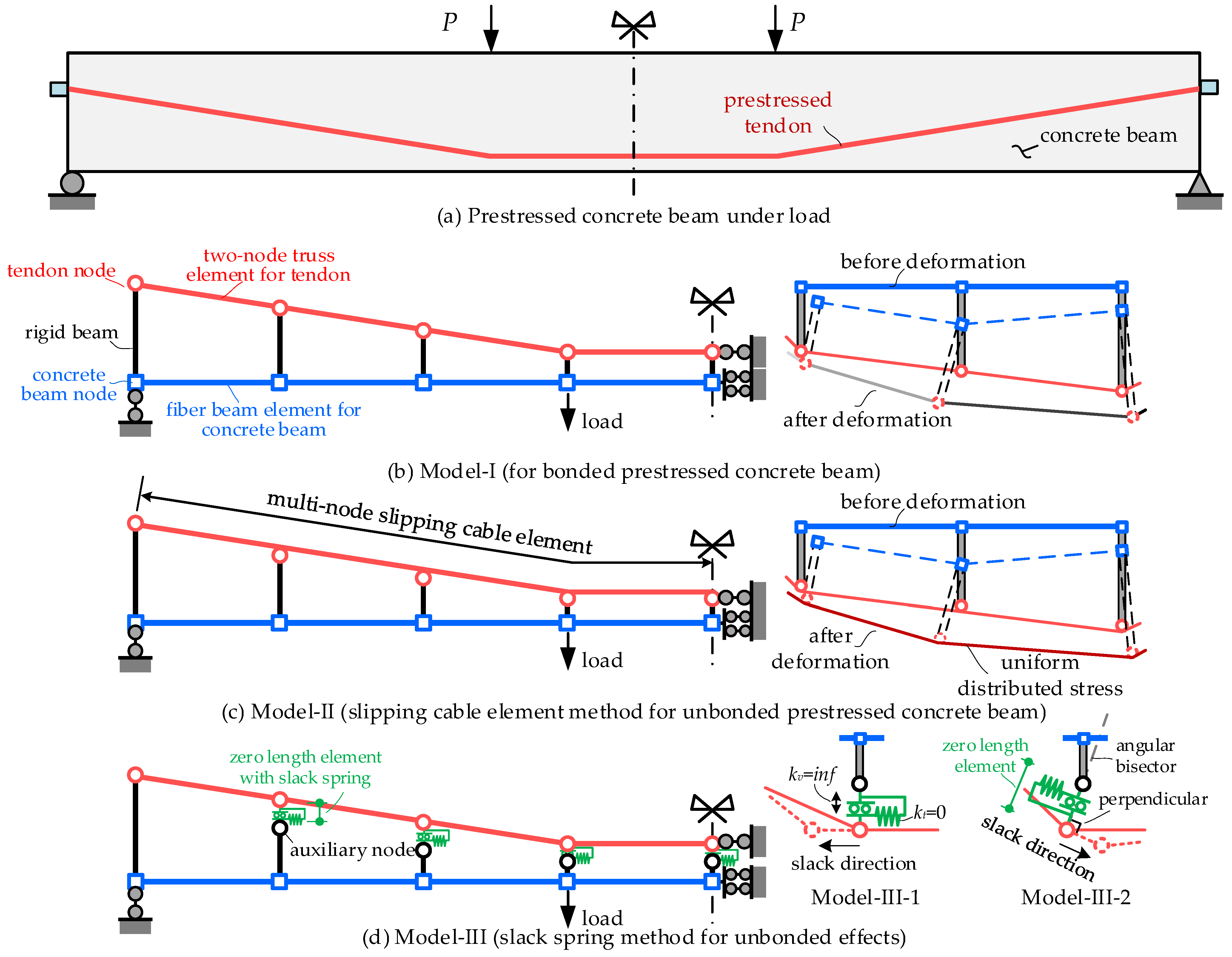
2.2. Modeling Schemes and Applicability Comparisons

From the view of computational efficiency, the fiber beam element-based model is usually considered more appropriate than the solid element model for the flexural performance analysis of prestressed concrete beams [39,40]. The basic modeling idea based on the nonlinear fiber beam element is shown in Figure 2. For the loading case in Figure 3a, the representative modeling schemes (semi-structural analysis model) for different bonding conditions are as depicted in Figure 3b–d. The main differences between these models for different bonding conditions are the adopted element types for tendons and the connections for concrete beams and tendons.
(1) Model I is the conventional bonded prestressed concrete beams model, as shown in Figure 3b. The concrete beam is modeled by the fiber beam elements, and the tendons are modeled by the two-node truss elements. The concrete beam and tendons are meshed to ensure they have the same longitudinal coordinates, and the rigid beams are built between them to model the connections. With the rigid beam, the tendon elongation will only be controlled by the deformation of the connected beam element, and the stress of the adjacent tendon elements will be independent. Therefore, the unbonded effects cannot be considered in Model I.
(2) In Model II, the new element type named the “slipping cable element” is used to model the fully unbonded tendons. For unbonded members, the critical problem is to model the constant stress mechanical characteristics within the whole unbonded tendon length. This element type takes the tendon between anchorage points as an entire element, one which consists of multiple segments and nodes, as shown in Figure 3c. The element elongation will be calculated during each iterative step to ensure the same stress within the tendon. The finite element formulas have been reported in references [33,34,35]. This method has been verified to be accurate for modeling unbonded tendons. However, this new element type has not been developed in the general finite element software, and the self-compiled program is needed [41]. Moreover, the downside is that this method can only be used for fully unbonded members, not partially bonded members, due to the co-existing bonded and unbonded conditions beyond the element assumption.
(3) Model III is an improvement of Model I. The tendons are also modeled by the traditional truss element. However, the additional auxiliary nodes were built at the location of the tendon centroid to model the surrounding concrete. The rigid beam elements were set between concrete beam nodes and auxiliary nodes to transform the structural deformation to the surrounding concrete. The connections between the tendon nodes and auxiliary nodes were coupled for vertical degree-of-freedom (DOF) (kv equals a considerable value) and set to zero-stiffness spring (kt = 0) in the longitudinal direction (called “slack spring method” in this paper), as shown in Figure 3d. In this way, the stresses in the adjacent truss elements can be realized as approximately equal. Further, if we set kt to be a considerable value, the model can also be applied to the analysis of bonded members. Chen et al. [37] applied this modeling method for the internal unbonded tendons using the existing element types in OpenSees software [42]. This is a worthwhile method, because it can be realized by the built-in element types in most finite element software. However, there are still two issues that need to be clarified. First, Chen et al. [37] only analyzed the straight unbonded prestressed members. It is necessary to discuss the applicability to more complicated tendon profiles, such as curvilinear internal unbonded and draped external tendons. Then, it needs to be determined whether the “slack spring method” can be popularized to analyze the behaviors of partially bonded members by adjusting the different values of kt. This paper mainly contributes to researching and validating these two problems and further discusses the effects of different bonding conditions on structural performance.
For Model III, taking a tendon node as an analytic target, the force diagram can be drawn as in Figure 4. The static equilibrium equations built in x and y directions are shown in Equation (1). The combination of two equations yields Equation (2). If unbonded effects are satisfied, the condition T1 = T2 ≠ 0 must be satisfied. Equation (2) can be transformed into Equation (3). This is simple but valuable. The prerequisite for the unbonded effect to be satisfied by Model III is that the direction of the zero-length element should be on the bisector line of the angle between the truss elements. For the straight unbonded tendon, the direction obtained by Equation (3) is vertical. However, for the tendons with curved or draped profiles, the suggested direction of the zero-length element should be determined according to the slope of the tendon profile rather than the descriptions adopted by Chen et al. [37]. To verify this conclusion, we build two models for Model III, named Model III-1 (zero length element along with the vertical direction) and Model III-2 (zero length element along with the angular bisector), respectively.
F x = 0 ,   T 1 sin α 1 + T 2 sin α 2 + N sin θ = 0 F y = 0 ,   T 1 cos α 1 + T 2 cos α 2 + N cos θ = 0
T 1 sin θ α 1 + T 2 sin θ α 2 = 0
θ = α 1 + α 2 2
However, we noticed that the tendon’s dip angle and structural deformation will constantly change under loading. So, even though we define the zero-length element by the direction of Equation (3), the angular deviation δ will inevitably appear following the beam deflection. Defining the coefficient β = 1 − (T1/T2) describes the degree of non-uniform distribution between two truss elements. Substituting θ = (α1 + α2)/2 + δ into Equation (2), Equation (4) can be obtained. With the increase of δ caused by structural deformation, the nonuniformity relative to the adjacent truss element will increase. The suggested element direction in Equation (3) can decrease the initial deviation. In addition, the angular deviation δ is mainly caused by structural deflections, which is small compared with (α1 + α2)/2, for purposes of practical engineering. The effects of δ will be analyzed in the following section.
β = 1 T 1 T 2 = 2 tan α 2 α 1 2 / tan δ + 1
Table 1 shows the summary and comparisons between different modeling schemes. It can be seen that Model III is a promising method for members with different bonding conditions. The model validation and detailed discussion are presented in the following section.

2.3. Computational Procedure

All of the analysis models are built in OpenSees V2.5.0 software [42] because of its open-source advantages and powerful nonlinear analysis capability. In particular, the slipping cable element in Model II is built employing the program pre-developed by the authors in OpenSees v2.5.0 [32,33]. The other models are all built using the built-in element type in OpenSees v2.5.0 software. In the numerical model, the concrete beam element size is 50 mm, and the tendon element is meshed with the same element amounts and nodal coordinate in the longitudinal direction as the concrete beam.
The materials used in the analysis mode include concrete, steel reinforcement, and prestressing tendon. The concrete is simulated by the “Concrete 02” model [43]. The “ReinforcingSteel” model is employed to simulate the material nonlinearity of steel reinforcement according to the suggestion of reference [44]. The “Steel 02” model is adopted to simulate steel tendons [33].
The numerical models are loaded from two analysis steps. First, the prestressing force is applied to the tendon by way of initial stress according to the control tension stress. Then, externally applied forces are loaded on the model by displacement-controlled loading up to failure.

3. Model Verification

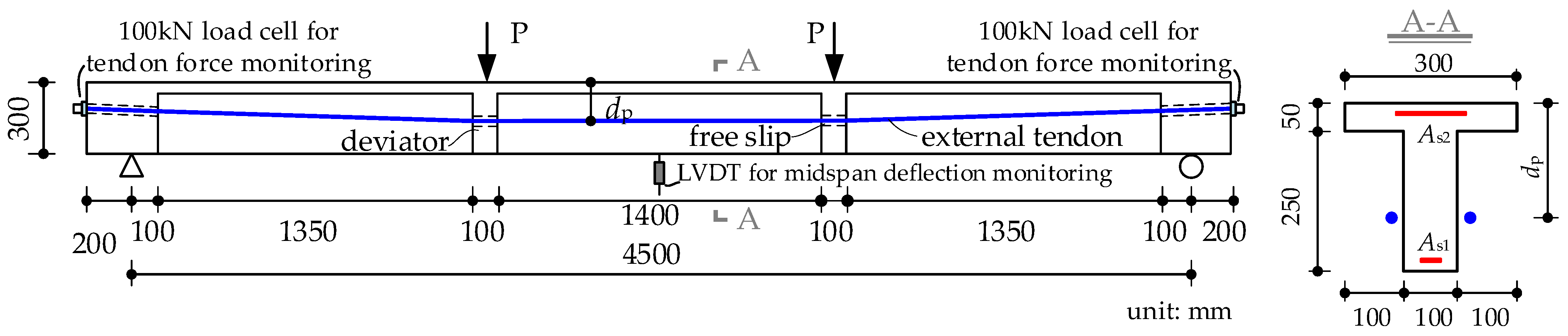
3.1. Externally Prestressed Concrete Beam

The specimen named SSS1, in the experiment conducted by Au et al. [45], is taken as an example in order to verify the feasibility of the mentioned modeling schemes for the unbonded behavior simulation of the external tendon. The specimen was a simply supported concrete beam with a span length of 4.5 m. The structural design details and loading schema are shown in Figure 5. The material characteristics of concrete, rebar, and tendon are listed in Table 2. The external tendons were designed with a harped profile, the effective tendon depth dp of which was 112 mm at the beam end and 168.8 mm at the midspan. The external tendon was post-tensioned at 28 days of age, then monotonically loaded up to failure on the same day. Under four-point loading, the failure is caused by the tensile reinforcement yield and the top flange’s concrete crushing at the midspan cross-section. Three different models mentioned in Section 2 are employed to predict the whole-process structural behavior.
Figure 6 compares the predictions and the test results of load-deflection and deflection-tendon stress increment curves. The comparisons clearly show the noteworthy influences of the slip effect of the external tendon at the deviators on flexural performance. For Model I, the slip effects at the deviators are not considered. The tendon elongation is independent of the different tendon segments, which is subtly different from the actual behavior of the external tendon. The tendon elongation of Model I mainly occurred at the middle tendon segment, “Seg-2”, causing the higher tendon stress increment and structural flexural capacity. Model I overestimates the structural stiffness and flexural capacity after the mild rebar yielding, without considering the slip effects. For Model II, the external tendon is taken as a whole element, and the slip effects are naturally considered during the deriving of the finite element formula. On the basis of Model I, the longitudinal relaxation spring determined by Equation (3) is introduced at the deviators in Model III to consider the slip effects. The tension redistribution phenomenon among the tendon segments will occur in Model III due to the zero “slack spring” stiffness in the longitudinal direction. In equilibrium, the tendon stress is approximately equal anywhere within the tendon length, satisfying the assumption of unbonded effects. Model II and Model III analysis results are very close and agree well with the tests for flexural capacity and tendon stress increments.
Further, let us increase the midspan dp to 1/10 span length (dp = 450 mm), and the dip angle θ of the draped tendon to 35.3°. For this situation in which the included angle between the tendon segments is large, the orientation of the relaxation spring at the deviators in Model III has non-negligible effects on the flexural behaviors. Three numerical models are built and analyzed for comparisons, including Model II with slipping cable element, Model III with longitudinal relaxation spring along the beam length (named Model III-1), and Model II with tangential relaxation spring (named Model III-2). The analysis results are plotted in Figure 7 for comparison. It can be seen that the orientation of the relaxation spring will influence the results of the analysis, and merits attention. Model III-1 slightly underestimates the flexural capacity, by 3%. The reason for the deviation in Model II-1 is that the relaxation spring orientation is in the longitudinal direction, in which the horizontal component of Seg-1 equalizes the tendon force of Seg-2. So the tendon force of the middle segment of Seg-1 is smaller than that of Seg-2, causing a prediction of lower flexural capacity. With the suggested tangential relaxation orientation, which is perpendicular to the angle bisector of tendon segments (Model III-2), the analysis results are close to the slipping cable element model (Model II). It should be noted that the method exemplified by Model III-2 can be easily realized in the general finite element software without additional program development, like that of Model II.

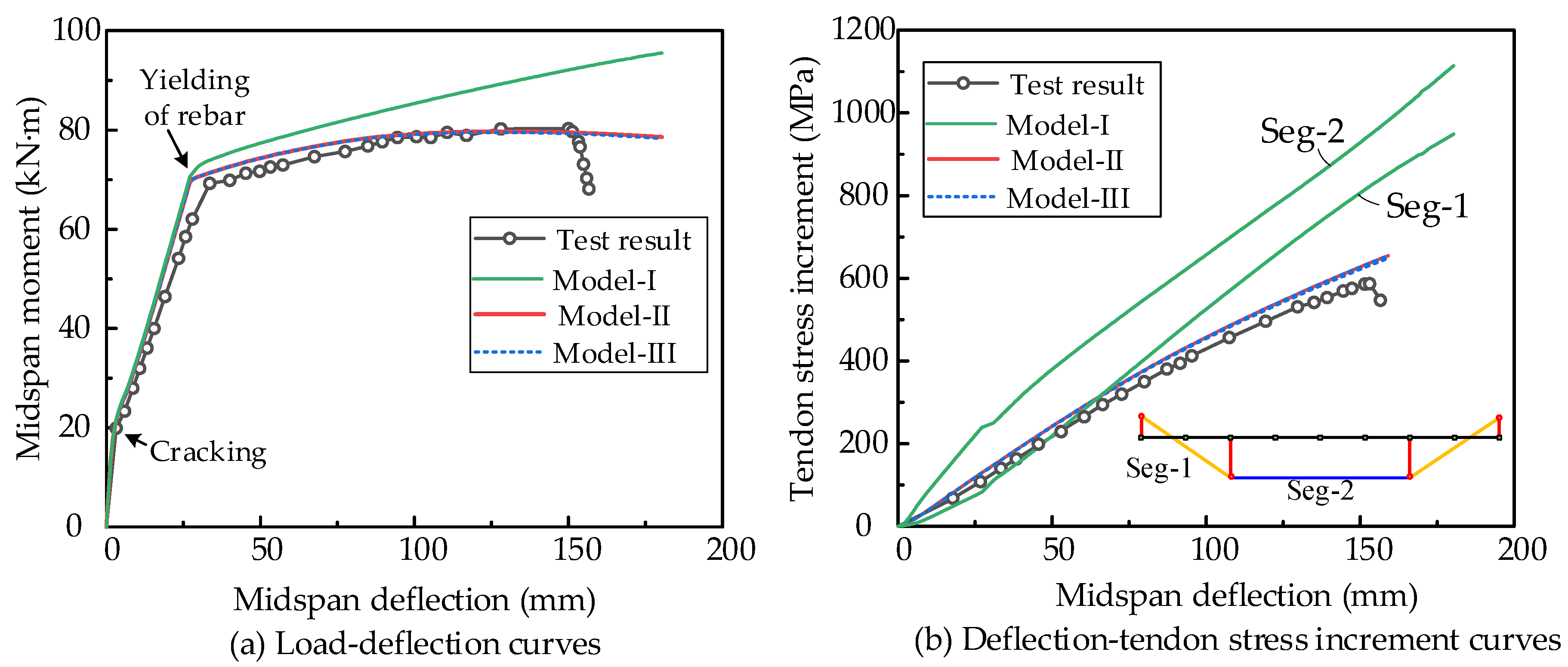
3.2. Internal Unbonded Prestressed Concrete Beam

A 4.8 m + 4.8 m continuous test beam with internal unbonded tendons, named YLA2 [46], is selected to verify and determine the applicability of the above-mentioned methods for modeling the internal unbonded tendons. The details of the structural dimensions, cross-section, and loading pattern are shown in Figure 8, and the related material parameters are listed in Table 3. The diameter of the steel reinforcement used was 12 mm, and its elastic modulus and yield strengths were 361 MPa and 200 GPa, respectively. The prestressing tendon’s yield strength, ultimate strength, and elastic modulus are 1680 MPa, 1941 MPa, and 197 GPa, respectively. The tendon profile was designed using the piecewise quadratic equations [46]. The relation between the beam deformation and the tendon elongation was more complicated than that of the straight tendon profile. The internal unbonded tendon was prestressed at 28 days of age, and then third-point loading was applied at each span up to failure. With the increasing load, the top mild rebar As2 at the middle support cross-section was first-yielded, and then flexural failure occurred at the midspan cross-section almost simultaneously. The tendon was still elastic at the ultimate, which differs from those of bonded members. The analysis results for load-deflection and load-tendon stress increment as determined by different modeling schemes, and their comparisons with the test results, can be seen in Figure 9. The method of Model I equivalently takes the specimen as bonded members, overestimating the flexural capacity and the tendon stress. The results of Model II and Model III-2, with the unbonded effects considered, are matched well with the tests for both flexural capacity and tendon stress increment. The slight deviations between predictions and tests are mainly caused by the possible friction and material randomness.
The effects of the orientation of the relaxation springs in Model III on the tendon stress distributions are further discussed here. For comparison purposes, we collect the tendon stress results from different models under the same midspan deflection of 40 mm. The discussed models include Model II with slipping cable element, Model III-1 with relaxation springs defined along the beam length direction, and Model III-2 with relaxation springs defined perpendicular to the angle bisector of tendon segments. The comparisons of the results are shown in Figure 10. The tendon stress in Model II is uniformly distributed within the whole element, which fully satisfies the frictionless and free-slip hypothesis. For Model III, there are some differences in the tendon stress along the beam length. The standard deviation of the tendon stress by the Model III-1 method is 5.54 MPa, while for Model III-2 with the suggested relaxation springs orientation, the standard deviation is reduced to 1.25 MPa, which is closer to the goal hypothesis. The relaxation springs method with the suggested orientation (Model III-2) can be adopted to simulate the behavior of the internally prestressed concrete beams, and the analysis results are close to those of the slipping cable element model (Model II).

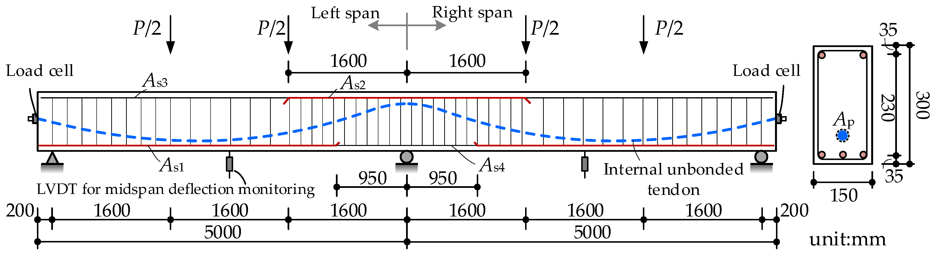
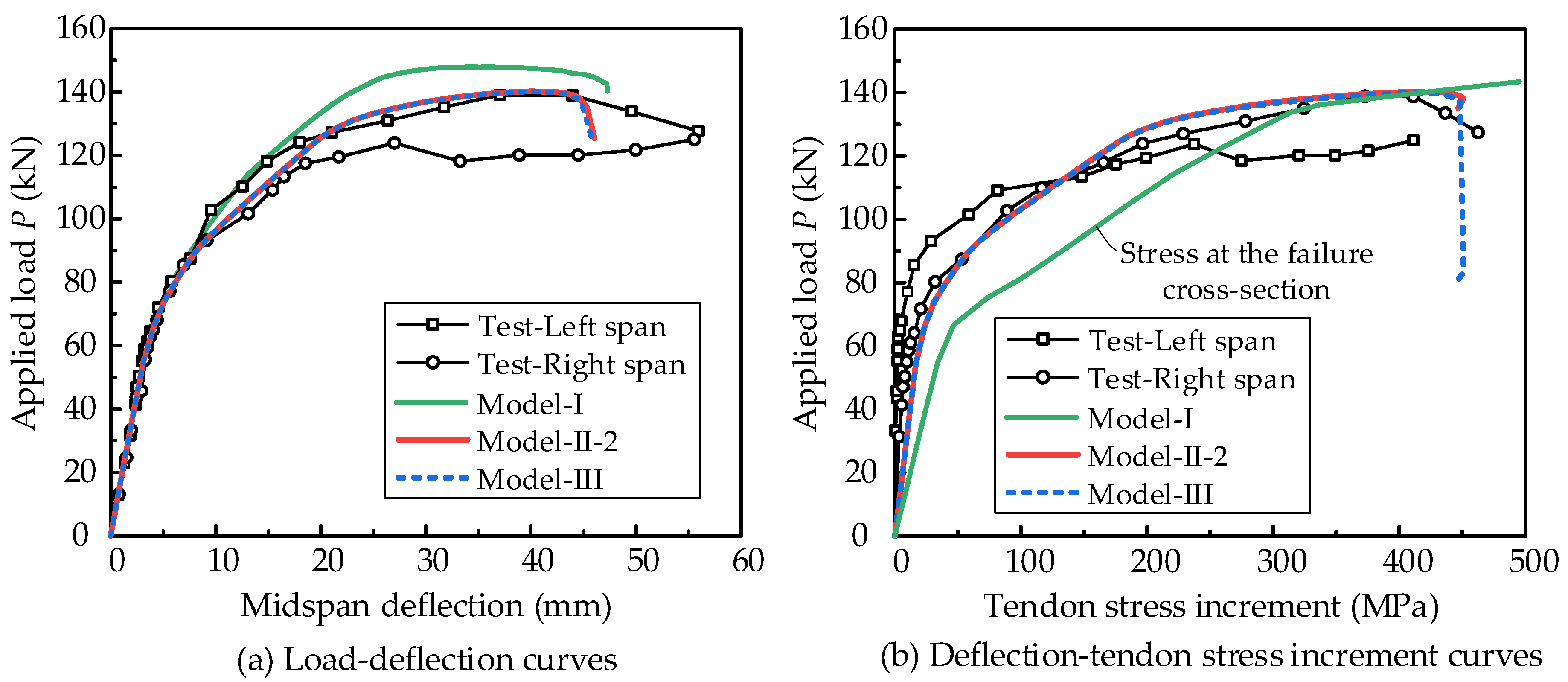
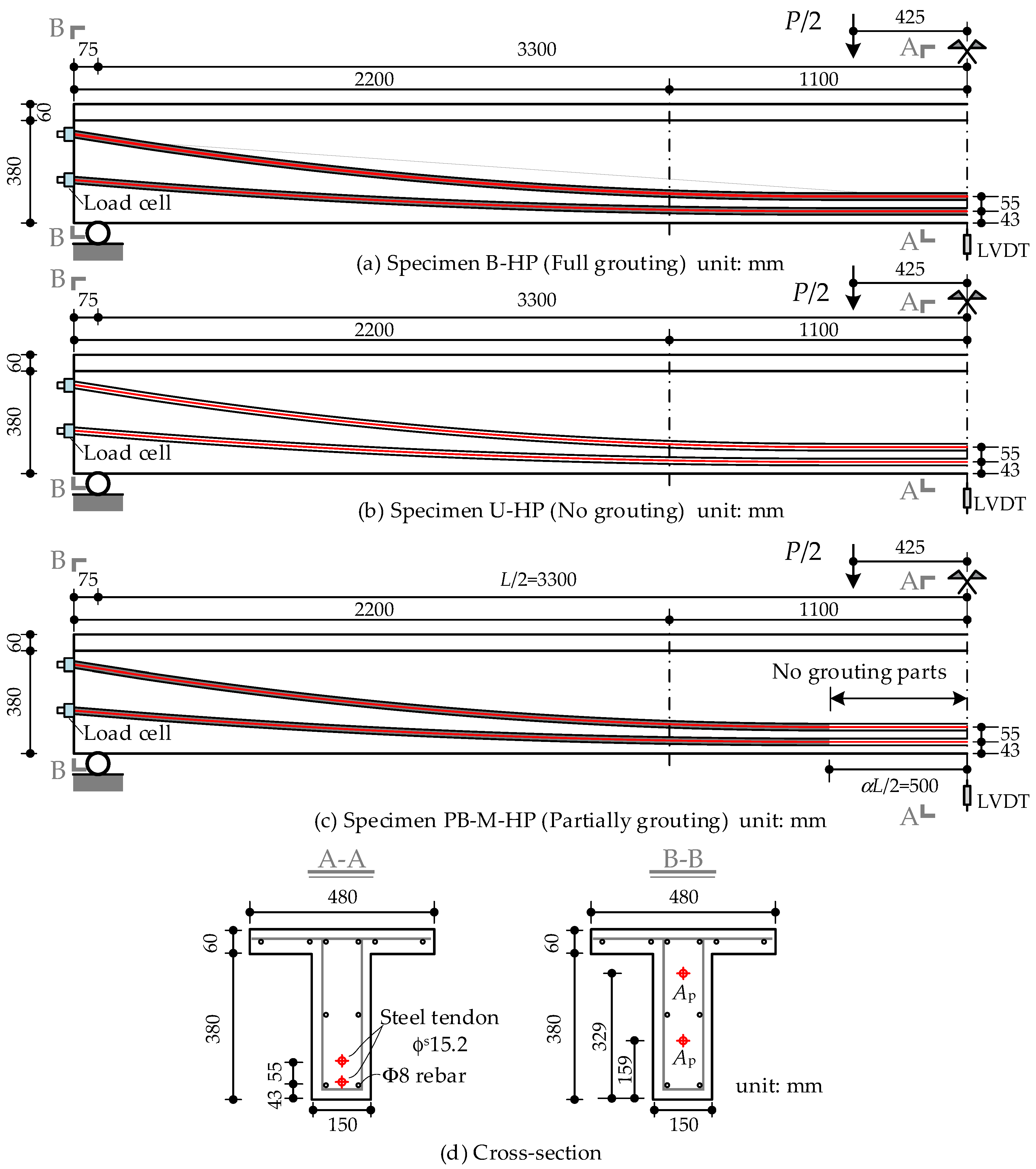
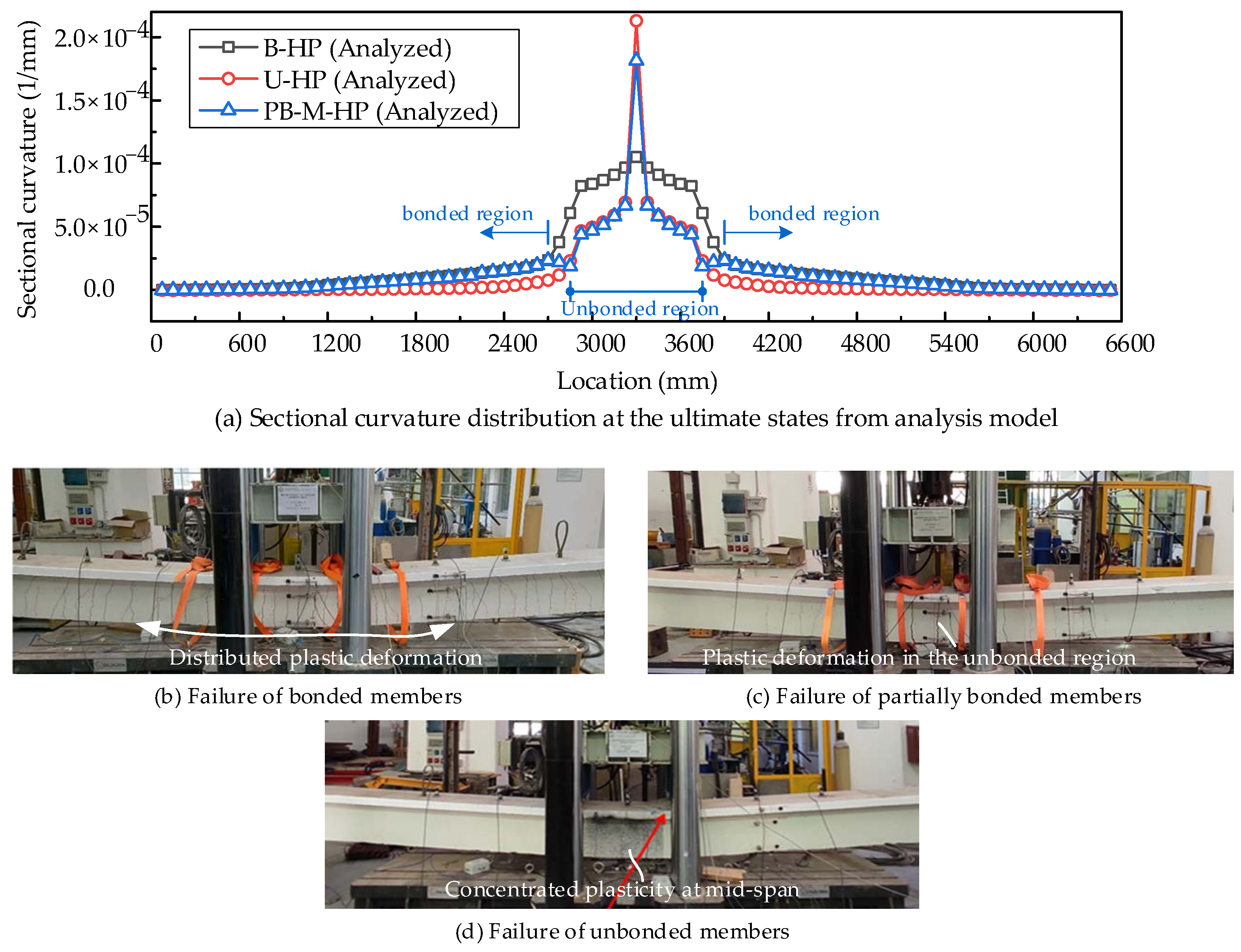
3.3. Partially Bonded Prestressed Concrete Beam

Losanno et al. [24] conducted a series of specimen tests to discuss the effects of grouting conditions on the flexural behaviors of prestressed concrete beams. Three specimens with different bonded states are collected here to verify the modeling method for partially bonded members, namely, B-HP (full grouting for bonded members), U-HP (no grouting for unbonded members), and PB-M-HP (no grouting at midspan for partially bonded members), respectively. The specimens were simply supported concrete beams with span lengths of 6.6 m. The design details of the specimens are shown in Figure 11, and the material properties are listed in Table 4. Tendon prestressing was imposed after 28 days of concrete curing. The actuator with 3000 kN loading capacity applied two-point loads at the midspan, spaced 850 mm apart, and all specimens were monotonically loaded to failure. The load cells were arranged at the beam ends to monitor the tendon stress variations, and the LVDT, with maximum strokes of 500 mm, was placed at the midspan to test the deflection change with increasing loads.
From the above analysis cases, we can conclude that Model III-2 can be used to model the behaviors of prestressed concrete beams with different bonded conditions by setting different connection stiffness values for the relaxation springs. For bonded members, the tangential and normal stiffness of the springs can be set to a significant value (such as 1 × 10¹⁸ N/mm, as in this paper). For unbonded members, the tangential stiffness can be set to zero for all springs. The zero-stiffness spring can be set in the unbonded area for partially unbonded members. Model I can only be used to model the bonded members, and Model II can only be used to model the unbonded members. Therefore, in this section, only Model III-2 is employed to analyze the behaviors of three specimens.
Figure 12 shows the analysis results and the comparisons with the tests. With the degradation of the bonding state (from B-HP, PB-M-HP, to U-HP), the structural flexural capacity and ultimate displacement are all decreased. The modeling method of Model III-2 can successfully capture the effects of bonding conditions on these responses.
As reported in reference [24], all of the specimens displayed flexural failure at the midspan cross-section, but the failure modes had some differences, due to the different bonding conditions. A significant opening crack was observed at the midspan cross-section, dominating the failure of unbonded specimen U-HP. The concrete beam was almost elastic in the other regions. For bonded specimen B-HP, the cracks were distributed in a broader range, and the crack spacing was smaller than in U-HP. The failure mode was between U-HP and B-HP for partially bonded specimen PB-M-HP, the major cracks of which appeared in the unbonded region and were slight in the other areas.
Based on the results of the analysis, the ultimate sectional curvature distribution at the peak loads is collected and compared with the experimentally observed failure modes, as shown in Figure 13. The locations of the more significant sectional curvature represent the failure cross-section with large plastic deformation. It can be clearly seen that the plastic deformation is concentrated at the midspan for unbonded specimen U-HP, and the other parts are almost elastic. The plastic deformations are distributed in a broader range for bonded specimen B-HP. Interestingly, for partially bonded specimen PB-M-HP, the sectional curvature distribution in the bonded area is close to the bonded members and close to unbonded members in the unbonded area. The results of the analyses match well with the observed failure mode from the tests, validating the effectiveness of the modeling method of Model III-2.
Based on the validation of these prestressed concrete beams with different bonding conditions, we can conclude that Model III (slack spring method) is an effective model for predicting structural deformation, carrying capacity, and failure modes. Moreover, we suggest setting the orientation of the zero-length element on the angular bisector line between the adjacent truss elements (Model III-2). The Model III-2 can improve the prediction accuracy of tendon stress distributions, compared with Model III-1.

4. Discussion

Based on the validated model, the Model III-2 method is further used to discuss the effects of the degree of unbonded conditions on the flexural performance. The specimen PB-M-HP by Losanno et al. [24] is employed here as the prototype beam for numerical analysis. The structural dimensions and the design details can be seen in Figure 11. The length of the unbonded area αL is taken as the only variable to be discussed. The unbonded area length αL is set from 0 to 6600 mm, with a step size of 600 mm (α ranges from 0 to 1). The control stress for prestressing is 800 MPa. The focused performance indicia include deformability (maximum deflection), carrying capacity, and self-centering behaviors.
With the specified loading pattern in Figure 11, all models are loaded up to failure, and the load-deflection curves are shown in Figure 14a. To compare the models’ self-centering behaviors, all numerical beams are firstly loaded to the same midspan deflection (100 mm) and then unloaded to zero force. The residual deformation res100 is obtained for comparisons, as shown in Figure 14b. The main indices of the results from these models, including maximum midspan deflection, peak load, and residual deformation res100, are listed in Table 5. The curves of these indices, along with the changing of the unbonded area length parameter α, are plotted in Figure 15. In Table 5 and Figure 15, the definition of the RES index follows the calculation of Chen et al. [37], and RES = 1 − res100/100.
Based on the comparisons, we find some interesting conclusions:
(1) Before the cracking of the concrete beam, the effects of the unbonded effects can be ignored. This result is consistent with the research conclusion of Bonopera et al. [12]. Their test showed that the specimen’s stiffness with a parabolic unbonded tendon and a bonded one is similar. However, the situation changes after the concrete beam cracks. The tangent slope of the load-deflection curve decreases, along with an increase of the unbonded area length. During this stage, the stiffness contributions of the tensile area are mainly from steel reinforcements and tendons. Along with the increase of unbonded area length, the tensile force increments of the tendon will decrease, causing a decrease of the tangent slope.
(2) As expected, the flexural capacity shows a decreasing trend with the increase of unbonded length, and the peak load of the unbonded member is 23.1% lower than that of the bonded member. Interestingly, we find that the variation of maximum deflection with unbonded length is not monotonic. The maximum deflection decreases for cases of α ranging from 0 to 0.4, and then increases for cases of α ranging from 0.4 to 1.0. The reason is revealed by the maximum deflection prediction equation of Peng et al. [16], as shown in Figure 16 and Equation (5). Values εcu and cu denote the concrete ultimate compressive strain and neutral axis height, respectively. Lp is the plastic hinge length of the idealized curvature distribution curve. From Equation (5), we find that the maximum deflection is mainly affected by Lp and cu. Based on the previous analysis in Figure 13a, we know that Lp and cu both decrease with the increase of unbonded length, causing the above-mentioned non-monotonic phenomenon. For cases with small unbonded lengths, the decrease of Lp dominates the reduction of maximum deflection. With a large unbonded length, the ultimate tendon stress decrease causes the reduction of cu and increase of maximum deflection.
v max = L p ϕ u L 4 = L p ε cu L 4 c u
(3) The residual deformation is mainly caused by the plastic of concrete, rebar, and prestressing tendon. Under the same structural deflection, the unbonded tendon stress is smaller than the bonded ones and even still elastic without plastic strain. Therefore, the self-centering performance of unbonded members is better than that of bonded members, as shown in Figure 15c.
In summary, the unbonded length significantly influences partially bonded concrete beams’ deformability, carrying capacity, and self-centering behaviors. Moreover, the influence rule is not simply monotonic for the deformability. Currently, study on the partially prestressed concrete beam is still limited, due to its more complicated behaviors and construction scheme. However, perhaps we can set an appropriate unbonded length according to the balance of deformability, flexural capacity, and self-centering properties to improve the overall structural performance, a possibility which should be further studied.

5. Conclusions

This paper systematically presents three modeling schemes for analyzing post-tensioned concrete beams with different bonding conditions: the conventional beam–truss element model (Model I), the slipping cable element (Model II), and the “slack spring method” (Model III). The slack spring model is recommended as the generally applicable model for analyzing post-tensioned concrete beams with different bonding conditions. The direction and stiffness of the slack spring in Model III are proposed to improve the accuracy of the analysis. The applicability of these models is analyzed and compared by verifications with the experimental beams, and the effects of unbonded length on flexural performance are parametrically analyzed. The conclusions are as follows:
(1)
Model I is adequate for the analysis of bonded prestressed members. Model II can capture the flexural behaviors of unbonded members well, but it cannot be used to analyze partially bonded members. Moreover, the application of Model II goes beyond the function of most finite element software, and a self-complied procedure is needed.
(2)
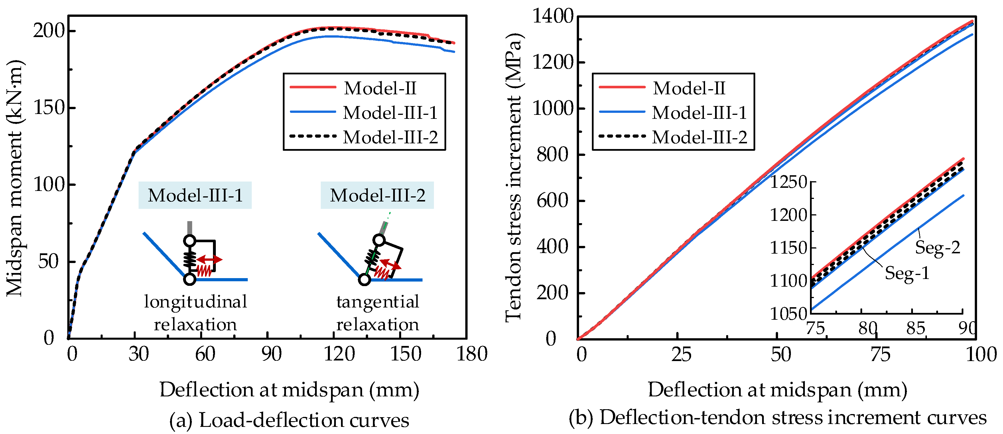
Model III is applicable for analyzing prestressed concrete beams with different bonding conditions (bonded, unbonded, and partially bonded members). The prediction accuracy can be improved by setting the orientation of the zero-length element, along with the angular bisector between the adjacent truss elements (Model III-2).
(3)
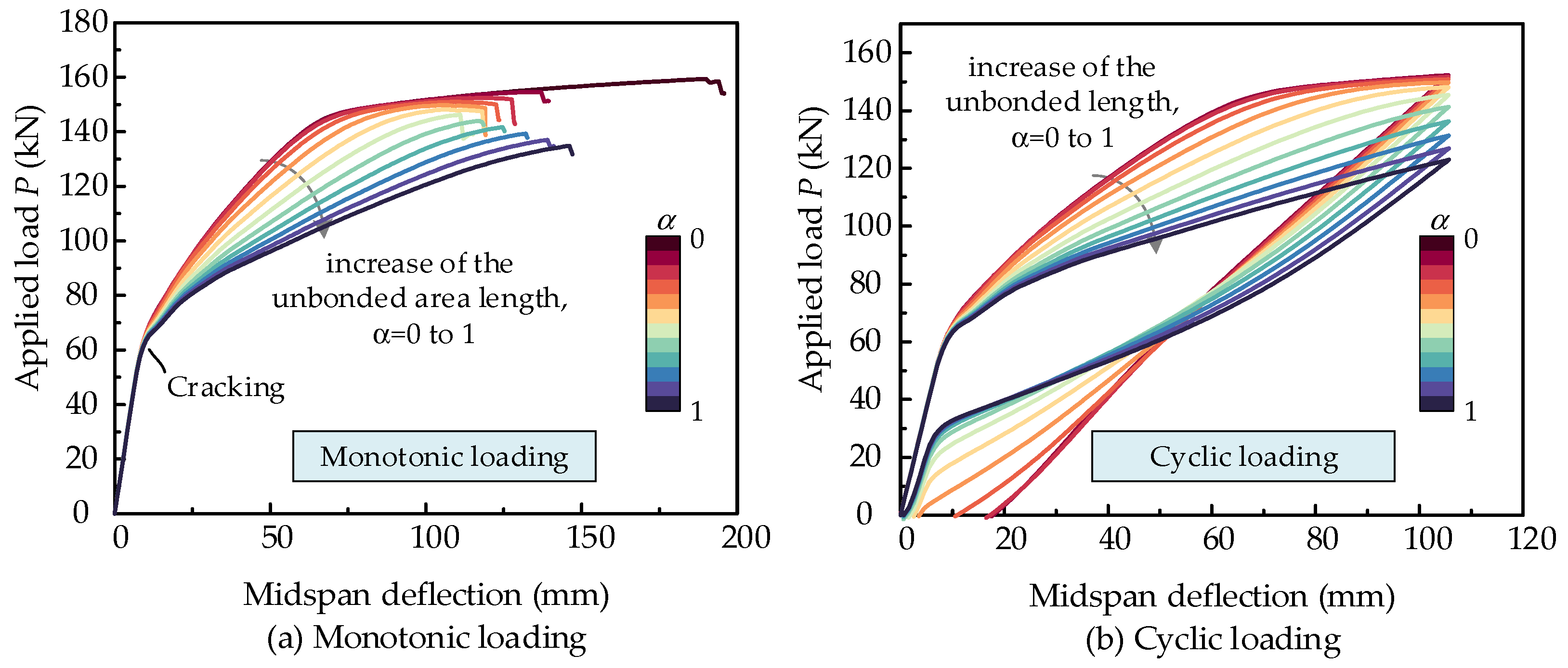
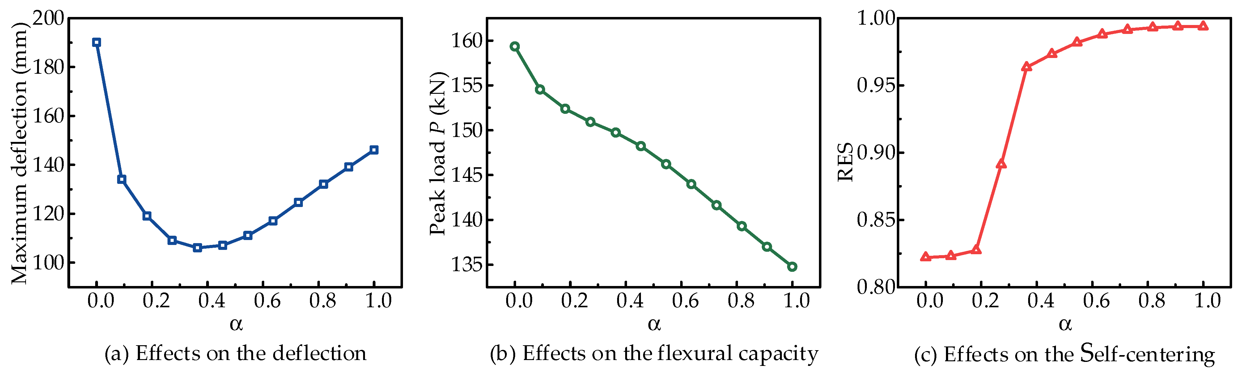
With increased unbonded length, the flexural capacity decreases, but the self-centering performance is improved. The effects of unbonded length on structural deformability are not monotonic, showing a trend of declining and then rising along with the increase in unbonded length.
(4)
An experimental study on the flexural performance of post-tensioned concrete beams with different bonding conditions needs to be conducted in the future to verify the modeling schemes thoroughly. More accurate information on the practicability of the proposed FE models can thus be provided. The influences of unbonded length on flexural capacity, deformability, and self-centering performance will be further experimentally verified.

Author Contributions

Conceptualization, W.Y., S.C. and F.J.; methodology, W.Y. and S.C.; software, S.C.; validation, S.C. and Y.S.; formal analysis, S.C.; investigation, S.C.; resources, Y.S.; data curation, Y.S.; writing—original draft preparation, S.C., F.J. and W.Y.; writing—review and editing, S.C., F.J. and Y.S.; visualization, Y.S.; supervision, F.J.; project administration, W.Y.; funding acquisition, F.J. All authors have read and agreed to the published version of the manuscript.

Funding

This research was funded by China Academy of Building Sciences Co., Ltd., Youth Fund Project, grant number 20221802331030015; Project of the Ministry of Housing and Urban-Rural Development No. K20200641; Project of Science and Technology Research Development Plan of China Railway, funding number N2023G012.

Data Availability Statement

The original contributions presented in the study are included in the article, further inquiries can be directed to the corresponding author.

Conflicts of Interest

Author Shangzhi Chen, Fangxin Jiang and Yue Sun are employed by the China Building Technique Group Co., Ltd. Author Wutong Yan is employed by the China Academy of Railway Sciences Co., Ltd.

Nomenclature

The symbols and acronyms used in the context:
AsiCross-sectional area of steel reinforcement;
ApCross-sectional area of tendon;
αCoefficient of unbonded length;
α1, α2Included angle between the tendon segment and the concrete beam;
βDegree of non-uniform distribution between two truss elements;
εcuConcrete compressive strain at ultimates;
AuSectional curvature at ultimates;
θIncluded angle between axial force N and x direction;
δAngular deviation of the tendon;
cuDepth of compression zone;
dpEffective height of tendon;
EcElasticity modulus of concrete;
EsElasticity modulus of steel reinforcement;
EpElasticity modulus of prestressed tendon;
fcCompressive strength of concrete prisms;
fcuCompressive strength of concrete cube;
ftTensile strength of concrete;
fpeEffective prestress of tendon;
fpyNominal yield strength of tendon;
fpuUltimate tensile strength of tendon;
fyYield strength of steel reinforcement;
LpPlastic hinge length;
NAxial force of the zero-length element;
ktLongitudinal stiffness of the slack spring;
kvVertical stiffness of the slack spring;
T1, T2Tendon force;
vmaxMaximum midspan deflection;
LVDTLinear variable differential transducer;
res100Residual deformation after unloading from 100 mm midspan deflection.

References

  1. Terán-Torres, B.T.; Elías-Chávez, A.A.; Valdez-Tamez, P.L.; Rodríguez-Rodríguez, J.A.; Juárez-Alvarado, C.A. Flexural Stiffness and Crack Width of Partially Prestressed Beams with Unbonded Tendons. Buildings 2023, 13, 2717. [Google Scholar] [CrossRef]
  2. Havez, A.A.; Al-Mayah, A. Flexural Strengthening of Concrete Structures Using Externally Bonded and Unbonded Prestressed CFRP Laminates-A Literature Review. J. Compos. Constr. 2023, 27, 03123001. [Google Scholar] [CrossRef]
  3. He, Z.Q.; Liu, Z. Stresses in External and Internal Unbonded Tendons_ Unified Methodology and Design Equations. J. Struct. Eng. 2010, 136, 1055–1065. [Google Scholar] [CrossRef]
  4. Oukaili, N.; Peera, I. Behavioral nonlinear modeling of prestressed concrete flexural members with internally unbonded steel strands. Results Eng. 2022, 14, 100411. [Google Scholar] [CrossRef]
  5. Mossor, K. Differences in moment redistribution in concrete beams prestressed with bonded and unbonded tendons. PCI J. 2022, 67, 23–34. [Google Scholar] [CrossRef]
  6. Fu, C.; Zhu, Y.; Wang, Y. Stiffness assessment of cracked post-tensioned concrete beams with unbonded tendons based on the cracking pattern. Eng. Struct. 2020, 214, 110599. [Google Scholar] [CrossRef]
  7. Alqam, M.; Alkhairi, F. Numerical and Analytical Behavior of Beams Prestressed with Unbonded Internal or External Steel Tendons: A State-of-the-Art Review. Arab. J. Sci. Eng. 2019, 44, 8149–8170. [Google Scholar] [CrossRef]
  8. Nakari, T.; Tulonen, J.; Asp, O.; Kytoelae, U.; Laaksonen, A. Experimental study of moment redistribution in continuous concrete beams prestressed with unbonded tendons. Struct. Concr. 2024, EA, 1–18. [Google Scholar] [CrossRef]
  9. Dogu, M.; Menkulasi, F. Flexural response of UHPC beams post-tensioned with internal unbonded tendons: Experimental study. Eng. Struct. 2023, 296, 116895. [Google Scholar] [CrossRef]
  10. Yuan, A.; He, Y.; Dai, H.; Cheng, L. Experimental Study of Precast Segmental Bridge Box Girders with External Unbonded and Internal Bonded Posttensioning under Monotonic Vertical Loading. J. Bridge Eng. 2015, 20, 04014075. [Google Scholar] [CrossRef]
  11. Heo, S.; Shin, S.; Lee, C. Flexural Behavior of Concrete Beams Internally Prestressed with Unbonded Carbon-Fiber-Reinforced Polymer Tendons. J. Compos. Constr. 2013, 17, 167–175. [Google Scholar] [CrossRef]
  12. Bonopera, M.; Liao, W.C.; Perceka, W. Experimental-theoretical investigation of the short-term vibration response of uncracked prestressed concrete members under long-age conditions. Structures 2022, 35, 260–273. [Google Scholar] [CrossRef]
  13. Nakari, T.; Laaksonen, A. Determination of the Stress Increase of the Unbonded Tendon in a Continuous Concrete Beam at Ultimate Capacity Using Nonlinear Analysis. Nord. Concr. Res. 2021, 64, 109–128. [Google Scholar] [CrossRef]
  14. Alqam, M.; Alkhairi, F.M.; Naaman, A.E. Stress at Ultimate in Prestressed Unbonded Tendons: Assessment of Code Equations and Recommendation. ACI Struct. J. 2021, 118, 177–187. [Google Scholar]
  15. Alqam, M.; Alkhairi, F.; Naaman, A. An Improved Methodology for the Prediction of the Stress at Ultimate in Unbonded Internal and External Steel Tendons. Arab. J. Sci. Eng. 2020, 45, 7915–7954. [Google Scholar] [CrossRef]
  16. Peng, F.; Xue, W. Calculating Method for Ultimate Tendon Stress in Internally Unbonded Prestressed Concrete Members. ACI Struct. J. 2019, 116, 225–234. [Google Scholar] [CrossRef]
  17. Sun, Y.; Wu, T.; Liu, X.; Zhang, B. Failure mode and flexural capacity of concrete beams prestressed with unbonded FRP tendons. Compos. Struct. 2022, 283, 114956. [Google Scholar] [CrossRef]
  18. Sun, Y.; Wu, T.; Liu, X. Design of concrete beams reinforced and unbonded prestressed with FRP bars based on serviceability requirements. Compos. Struct. 2022, 300, 116133. [Google Scholar] [CrossRef]
  19. Raiyan, E.; Khorgade, P.; Hueckler, A.; Schlaich, M. Nonlinear analysis of the stress increase in the CFRP tendon of a unbonded prestressed beam. Beton-Und Stahlbetonbau 2022, 118, 57–68. [Google Scholar] [CrossRef]
  20. Le, T.D.; Pham, T.M.; Hao, H.; Yuan, C. Performance of precast segmental concrete beams posttensioned with carbon fiber-reinforced polymer (CFRP) tendons. Compos. Struct. 2019, 208, 56–69. [Google Scholar] [CrossRef]
  21. Zheng, H.; Chen, D.; Ou, M.; Liang, X.; Luo, Y. Flexural Behavior of Precast UHPC Segmental Beams with Unbonded Tendons and Epoxy Resin Joints. Buildings 2023, 13, 1643. [Google Scholar] [CrossRef]
  22. Halder, R.; Yuen, T.Y.P.; Chen, W.-W.; Zhou, X.; Deb, T.; Zhang, H.; Wen, T.-H. Tendon stress evaluation of unbonded post-tensioned concrete segmental bridges with two-variable response surfaces. Eng. Struct. 2021, 245, 112984. [Google Scholar] [CrossRef]
  23. Zhang, F.; Zhao, G.H.; Wu, Y.F.; Zhang, Y. Effect of strand debonding on the shear strength of existing pretensioned PC hollow slab. Eng. Struct. 2023, 291, 116417. [Google Scholar] [CrossRef]
  24. Losanno, D.; Galano, S.; Parisi, F.; Pecce, M.R.; Cosenza, E. Experimental Investigation on Nonlinear Flexural Behavior of Post-Tensioned Concrete Bridge Girders with Different Grouting Conditions and Prestress Levels. J. Bridge Eng. 2024, 29, 04023121. [Google Scholar] [CrossRef]
  25. Hu, X.Y.; Xue, W.C.; Zheng, R.G. Hysteretic performance of prestressed concrete beams with AFRP tendons under cyclic loading. Struct. Concr. 2024, 25, 620–636. [Google Scholar] [CrossRef]
  26. Janet, M.L.; Chris, J.B. Experimental Study of Influence of Bond on Flexural Behavior of Concrete Beams Pretensioned with Aramid Fiber Reinforced Plastics. ACI Struct. J. 1999, 96, 377–385. [Google Scholar]
  27. Yuen, T.Y.P.; Halder, R.; Chen, W.-W.; Zhou, X.; Deb, T.; Liu, Y.; Tseng, Y.; Wen, T.-H. DFEM of a post-tensioned precast concrete segmental bridge with unbonded external tendons subjected to prestress changes. Structures 2020, 28, 1322–1337. [Google Scholar] [CrossRef]
  28. Tran, D.T.; Pham, T.M.; Hao, H.; Chen, W. Numerical investigation of flexural behaviours of precast segmental concrete beams internally post-tensioned with unbonded FRP tendons under monotonic loading. Eng. Struct. 2021, 249, 113341. [Google Scholar] [CrossRef]
  29. Le, T.D.; Pham, T.M.; Hao, H. Numerical study on the flexural performance of precast segmental concrete beams with unbonded internal steel tendons. Constr. Build. Mater. 2020, 248, 118362. [Google Scholar] [CrossRef]
  30. Jaiswal, O.R. Effect of prestressing on the first flexural natural frequency of beams. Struct. Eng. Mech. 2008, 28, 515–524. [Google Scholar] [CrossRef]
  31. Yan, W.; Jiang, F.; Chen, L.; Sun, Y. Proposals for Flexural Capacity Prediction of Precast Segmental Concrete Beam Prestressed with Internal Un-Bonded CFRP Tendons. Appl. Sci. 2023, 13, 6652. [Google Scholar] [CrossRef]
  32. Yan, W.T.; Chen, L.J.; Han, B.; Xie, H.B.; Sun, Y. Flexural Analysis Model of Externally Prestressed Steel-Concrete Composite Beam with Nonlinear Interfacial Connection. Appl. Sci. 2022, 12, 4699. [Google Scholar] [CrossRef]
  33. Yan, W.; Chen, L.; Han, B.; Xie, H.; Sun, Y. Numerical Model for Flexural Analysis of Precast Segmental Concrete Beam with Internal Unbonded CFRP Tendons. Materials 2022, 15, 4105. [Google Scholar] [CrossRef] [PubMed]
  34. Gao, W.; Lu, X. Modelling unbonded prestressing tendons in self-centering connections through improved sliding cable elements. Eng. Struct. 2019, 180, 809–828. [Google Scholar] [CrossRef]
  35. Moreira, L.S.; Sousa, J.B.M.; Parente, E. Nonlinear finite element simulation of unbonded prestressed concrete beams. Eng. Struct. 2018, 170, 167–177. [Google Scholar] [CrossRef]
  36. Brenkus, N.R.; Tatar, J.; Hamilton, H.R.; Consolazio, G.R. Simplified finite element modeling of post-tensioned concrete members with mixed bonded and unbonded tendons. Eng. Struct. 2019, 179, 387–397. [Google Scholar] [CrossRef]
  37. Chen, D.; Zeng, B.; Xu, Q.; Xu, X.; Xu, M. Effects of Prestressing Magnitude and Position on Seismic Performance of Unbonded Prestressed Concrete Beams. Buildings 2024, 14, 431. [Google Scholar] [CrossRef]
  38. Ayinde, O.O.; Zuo, X.-B.; Yin, G.-J. Numerical analysis of concrete degradation due to chloride-induced steel corrosion. Adv. Concr. Constr. 2019, 7, 203–210. [Google Scholar]
  39. Markou, G.; AlHamaydeh, M. Computationally-efficient high-fidelity nonlinear FEA of seismically isolated post-tensioned RC bridges. Structures 2024, 60, 105816. [Google Scholar] [CrossRef]
  40. Parente, L.; Addessi, D.; Spacone, E. A fiber beam element based on plastic and damage models for prestressed concrete structures. Eng. Struct. 2023, 292, 116501. [Google Scholar] [CrossRef]
  41. Pang, M.; Liu, X.; Dong, Y.; Lou, T. Numerical Assessment on Bonded and Unbonded Prestressed Concrete Beams. Buildings 2022, 12, 1658. [Google Scholar] [CrossRef]
  42. Mckenna, F.; Fenves, G. Opensees, version 2.5.0. Computer Software. UC Berkeley: Berkeley, CA, USA, 2015.
  43. Yan, W.-T.; Han, B.; Xie, H.-B.; Li, P.-F.; Zhu, L. Research on numerical model for flexural behaviors analysis of precast concrete segmental box girders. Eng. Struct. 2020, 219, 110733. [Google Scholar] [CrossRef]
  44. Liu, C.; Yang, Y.; Wang, J.-J.; Fan, J.-S.; Tao, M.-X.; Mo, Y.L. Biaxial reinforced concrete constitutive models for implicit and explicit solvers with reduced mesh sensitivity. Eng. Struct. 2020, 219, 110880. [Google Scholar] [CrossRef]
  45. Au, F.T.K.; Su, R.K.L.; Tso, K.; Chan, K.H.E. Behaviour of partially prestressed beams with external tendons. Mag. Concr. Res. 2008, 60, 455–467. [Google Scholar] [CrossRef]
  46. Lou, T.; Lopes, S.M.R.; Lopes, A.V. Nonlinear and time-dependent analysis of continuous unbonded prestressed concrete beams. Comput. Struct. 2013, 119, 166–176. [Google Scholar] [CrossRef]
Figure 1. Prestressed concrete beams with different bonding conditions.
Buildings 14 01682 g001
Figure 2. Truss–fiber beam element model for the prestressed concrete beam.
Buildings 14 01682 g002
Figure 3. Modeling schemes for prestressed concrete beams with different bonding conditions.
Buildings 14 01682 g003
Figure 4. Connection and force decomposition of tendon node for Model III.
Buildings 14 01682 g004
Figure 5. Dimension details and loading schema of specimen SSS1.
Buildings 14 01682 g005
Figure 6. Comparisons using the experimental results of specimen SSS1.
Buildings 14 01682 g006
Figure 7. Effects of the relaxation spring orientation on the flexural behaviors.
Buildings 14 01682 g007
Figure 8. Details of the specimens YLA2 and YLC2.
Buildings 14 01682 g008
Figure 9. Analysis results for comparisons between different modeling schemes.
Buildings 14 01682 g009
Figure 10. Tendon stress distribution along the beam length under the same deflection.
Buildings 14 01682 g010
Figure 11. Design details of the specimens with different grouting conditions.
Buildings 14 01682 g011
Figure 12. Analysis results of comparisons for cases with different bonded conditions.
Buildings 14 01682 g012
Figure 13. Failure modes comparison based on the results of the analysis.
Buildings 14 01682 g013
Figure 14. Load-deflection analysis results of numerical models with different bonding conditions.
Buildings 14 01682 g014
Figure 15. Curves of maximum deflection, peak load, and RES index, along with the parameter α.
Buildings 14 01682 g015
Figure 16. Failure mode and idealized curvature distribution of the prestressed concrete beam.
Buildings 14 01682 g016
Table 1. Comparisons between the modeling schemes for different bonding conditions.
Modeling SchemesApplicabilityElement TypeCan It Be Used in General FE Software?Validation
Bonded MembersUnbonded MembersPartially Bonded MembersConcrete BeamTendon
Model IYesNoNoBeamTrussYesYes
Model IINoYesNoBeamSlipping cable elementNoYes
Model III-1YesYesYesBeamTrussYesNo
Model III-2YesYesYesBeamTrussYesNo
Table 2. Material characteristics for specimen SSS1.
SpecimenBottom RebarTop RebarConcreteTendon
As1 (mm2)fy (MPa)As2 (mm2)fy (MPa)fc (MPa)ft (MPa)Ec (GPa)Ap (mm2)fpe (MPa)Ep (GPa)
SSS140254931749258.33.050.7198357201.9
Table 3. Parameters for the continuous test beams with internal unbonded tendons.
SpecimenAs1 (mm2)As2 (mm2)As3 (mm2)As4 (mm2)fc (MPa)ft (MPa)Ec (GPa)Ap (mm2)fpe (MPa)Ep (GPa)
YLA2452.4
(4Φ12)
226.2
(2Φ12)
226.2
(2Φ12)
226.2
(2Φ12)
36.73.8536.21401196197
Table 4. Parameters for partially bonded prestressed concrete beam.
SpecimenConcreteSteel Reinforcement A8Tendon As 15.2
fcu (MPa)Es (GPa)fy (MPa)Ap (mm2)Ep (GPa)fpe (MPa)fpy (MPa)fpu (MPa)
B-HP33.8200450140203.4716.517821969
U-HP33.8200450140203.4773.517821969
PB-M-HP33.8200450140203.4740.017821969
Table 5. Analysis results of the numerical models.
αMaximum Deflection (mm)Peak Load P (kN)Residual Deformation res100RES Index
0.0190.1159.317.8000.822
0.1134.1154.517.7000.823
0.2119.1152.417.2700.827
0.3109.1150.910.8900.891
0.4106.1149.73.6600.963
0.5107.1148.22.6790.973
0.5111.1146.21.8170.982
0.6117.1144.01.2150.988
0.7124.6141.60.8720.991
0.8132.1139.30.7070.993
0.9139.1137.00.6260.994
1.0146.1134.80.6300.994
Disclaimer/Publisher’s Note: The statements, opinions and data contained in all publications are solely those of the individual author(s) and contributor(s) and not of MDPI and/or the editor(s). MDPI and/or the editor(s) disclaim responsibility for any injury to people or property resulting from any ideas, methods, instructions or products referred to in the content.

