Article

Design and Verification of Experimental Device for Pressurized Bubbling Absorption and Transport Characteristics in Vacuum Environment

by
Jialiang Gao
1,2,
Gang Wang
1,3,*,
Jitong Li
1,2,
Xiaoyan Cui
1,
Yaxuan Xiong
1,
Xiaoshu Lü
4,5 and
Xuejing Zhang
6
1
Beijing Key Laboratory of Heating, Gas Supply, Ventilation and Air Conditioning Engineering, Beijing University of Civil Engineering and Architecture, Beijing 100044, China
2
Beijing Building Energy Efficient Comprehensive Utilization Engineering Center, Beijing 100044, China
3
Jiangsu Baixue Electrical Appliances Co., Ltd., Suzhou 215500, China
4
Department of Electrical Engineering and Energy Technology, University of Vaasa, P.O. Box 700, FIN-65101 Vaasa, Finland
5
Department of Civil Engineering, Aalto University, P.O. Box 12100, FIN-02130 Espoo, Finland
6
CLP Systems Construction Engineering Co., Ltd., Beijing 100141, China
*
Author to whom correspondence should be addressed.
Buildings 2024, 14(6), 1685; https://doi.org/10.3390/buildings14061685
Submission received: 28 March 2024 / Revised: 16 May 2024 / Accepted: 27 May 2024 / Published: 6 June 2024
(This article belongs to the Section Building Energy, Physics, Environment, and Systems)

Abstract

:
To explore the dynamics of flow and heat transfer behaviors associated with bubbles during solution absorption in a vacuum environment, we present the design of an experimental setup for measuring the absorption and transport properties of bubbles in a pressurized vertical tube. The structure and operational principle of the setup are detailed. The reliability and accuracy of the system are validated through a series of experiments, including vacuum level maintenance, bubble flow verification, and energy checks. The findings reveal that the supercharging technology effectively facilitates bubble absorption under negative pressure. Over a 12 h period, the system vacuum level elevates by only 2.33%, indicating a minimal gas leakage rate of 2.4 mL/h and affirming the device’s exceptional reliability. The observed bubble formation, rise, collision, coalescence, and rupture behaviors in the experiment are consistent with previous studies on bubble flow. The maximum relative deviations of temperature and concentration at the solution and cooling water outlets are 0.08%, 0.02%, and 0.01%, respectively, validating the device’s excellent accuracy. Additionally, the energy check experiments, performed with varying solution inlet temperature and flow rate, reveal the maximum errors of 10.4 J and 12.5 J, respectively, demonstrating the device’s satisfactory accuracy. In summary, this work lays a robust experimental foundation for subsequent investigations into the transport properties and transfer mechanisms of bubble absorption in a vacuum environment.

1. Introduction

Bubble absorbers are gas–liquid contact devices that exhibit advantages such as low transfer resistance, large interfacial area, simple structure, and low cost. These attributes have led to their widespread applications in various fields such as chemical, biological, environmental, and refrigeration applications [1]. In comparison to the downflow absorption method, bubble absorption involves introducing absorbed gas into the liquid in the form of bubbles [2], which are completely surrounded by the liquid, leading to a larger absorption area, better wettability, and more thorough gas–liquid mixing [3]. Consequently, studying the transport characteristics of bubble absorption holds great theoretical significance for absorber design [4] and the enhancement of heat pump system performance. Bubble absorption is a complex process involving the movement of gas–liquid phases and heat and mass transfer. It primarily relies on bubble flow within the stagnant or flowing liquid phase to drive the mass and heat exchange of gas phase components, accompanied by a coupling effect between mass and heat transfer. Therefore, it is necessary to develop an experimental device that can explore the flow dynamics, heat and mass transfer quantities, and governing transfer laws of bubble absorption through experiments to determine the average heat and mass transfer coefficients of absorbers.
In the industrial sector, bubble absorbers have garnered significant attention due to their outstanding thermodynamic performance. Regarding flow issues within bubble absorbers, Kemoun et al. [5] developed a visual high-pressure bubble collision experimental device consisting of a CREL scanner, a porous plate distributor, and a stainless steel bubble column, enabling the observation of the gas retention phenomenon in a pressurized bubble column. The study found that the average gas content of the cross-section increases with the increase in pressure and surface gas velocity. Wu et al. [6] constructed a vibration experimental device for visual bubble absorption of R134a-DMAC(Chlorotetrafluoroethane-Dimethylacetamide) to investigate the bubble behaviors and two-phase flow patterns under vibrating conditions, consisting of a working fluid preparation system, a vibration table system, a reaction container system, and a data acquisition system. The results show that bubble behavior and two-phase flow morphology become more complex and perturbed under vibration conditions, and bubble shaking and collapse phenomena are also observed. Kang et al. [7] utilized a high-speed camera, stainless steel steam distributor, and ammonia container to capture the flow behavior of bubbles. They also measured the volume diameter of bubbles using an ammonia–water bubble absorption visual flow experimental device. It was found that the residence time increased with the increase in the initial bubble diameter and liquid concentration, and the initial bubble diameter increased with the increase in the orifice diameter. Kim et al. [8] designed an experimental apparatus of a countercurrent plug flow absorber with a test section made entirely of transparent materials to obtain the absorption height and solution flow pattern in an ammonia–water mixture. As a result, it is found that the local heat and mass transfer coefficient on the liquid side of the absorber is greatly influenced by the flow pattern. The heat and mass transfer coefficient at the frost flow region is higher than that at the slug flow region due to flow disturbance and random fluctuation. The solution flow rate and gas flow rate have influence on the local heat and mass transfer coefficient at the frost flow region. However, it is insignificant at the slug flow region. Li et al. [9,10] developed a visualization experimental device for the movement of multiple CO2 bubbles in methanol/Al2O3 nano-absorbents using a mass flow controller (MFC) to accurately control the gas flow rate. The results show that the leading bubble has a significant impact on the following bubbles, including velocity increment, bubble shape deformation, and flow instability, and the bubble diameter is only determined by the gas flow rate and the orifice diameter of the orifice area. Roy et al. [11] constructed a bubble column reaction experimental device with a higher liquid holdup rate to obtain the bubble flow patterns in a bubble column. As a result, the overall holdup is reported to decrease with increasing column diameter due to large bubble holdup. Xu et al. [12] built a visual experimental device for bubble absorption in a vertical tube to investigate the flow pattern transition during the bubble absorption process of R124-DMAC. The study found that the ratio of slug flow of the bubble absorption heights will increase with vapor flow rate rising. The ratio and the bubble absorption heights will be reduced when a multi-orifice nozzle is applied in the absorber under the same flow area condition, but the pressure difference will increase. Although the above studies have conducted research on flow characteristics, they have not conducted coupling studies on flow and heat and mass transfer, and lacked research on the impact of flow on heat and mass transfer.
Concerning heat and mass transfer in bubble absorption, Kang et al. [13] designed a bubble absorption mass transfer measurement experimental device controlled by a pressure-regulating valve and a stop valve to explore the mass transfer coefficient of ammonia–water bubble absorption. The study proposes a new experimental correlation for volumetric bubble diameter with an error band of 15%, which can be used to calculate the mass transfer coefficient. Jiang et al. [14,15] constructed a visualization experimental device for heat and mass transfer characteristics of bubble absorption inside a vertical tube to investigate the impacts of R124-DMAC gas flow rate and absorption solution flow rate on heat and mass transfer in bubble absorption. The results show that the total heat transfer coefficient and volumetric mass transfer coefficient increase with the increase in steam and solution flow rates, and decrease with the increase in solution inlet temperature, mass fraction, and nozzle aperture. Kim et al. [8] developed an experimental apparatus for measuring local heat and mass transfer coefficients on the liquid side of an ammonia–water vertical countercurrent plug flow absorber. The control volume method and heat and mass transfer analogy are employed to solve the combined heat and mass transfer problem. Bubble absorption is a complex gas–liquid two-phase flow process. However, there remains an incomplete understanding of the experimental exploration of flow characteristics, heat and mass transfer behaviors, and governing transfer laws within bubble absorbers. There is a lack of experimental devices that can effectively couple flow status of bubbles with heat and mass transfer characteristics.
In the realm of refrigeration and air conditioning, research on bubble characteristics and heat transfer properties in absorbers primarily focuses on ammonia–water and R134a-DMAC bubble absorption. Kim et al. [16] designed an experimental setup for a vertical countercurrent plug flow absorber employing ammonia–water as the working fluid. The results show that the heat and mass transfer coefficient at the frost flow region is higher than that at the slug flow region due to flow disturbance and random fluctuation. Kim et al. [17] developed an efficient NH3/H2O absorption experimental device incorporating an adjustable regulator and a visualization tool for bubble behavior to explore the bubble absorption mechanism in binary nanofluids. It is found that the absorption length decreases with the increase in dilute solution flow rate and the decrease in gas flow rate, and the absorption length decreases with the increase in coolant side heat transfer performance. Wu et al. [6] constructed a bubble absorption experimental device for R134a-DMAC working fluid utilizing a concentric annular tube reaction vessel to study the bubble absorption process under vibrating conditions. The results show that bubble behavior and two-phase flow morphology become more complex and perturbed under vibration conditions, and bubble shaking and collapse phenomena are also observed. Wu et al. [18] investigated the impact of a magnetic field on the heat transfer of ammonia–water bubble absorption in nanoscale Fe3O4 fluid. They established an experimental setup for magnetically enhanced ammonia–water bubble absorption and heat transfer. The results show that the combined effect of nanoferrofluid and external magnetic field significantly enhances the adsorption of ammonia bubbles. Donnellan et al. [19] built a bubble absorption experimental device for assessing the absorption performance of bubbles in concentrated lithium bromide aqueous solution at atmospheric pressure. The overall absorption rate was found to increase with increasing bubble initial diameter. However, absorption chillers operate under vacuum conditions, where gas buoyancy fails to overcome liquid resistance. This limitation hinders the application of bubble absorption technology in absorption chiller units.
Drawing on key technologies for absorption with pressurization [20,21,22], this paper presents the design of a pressurized solution bubble absorption experimental apparatus that employs a variable frequency booster pump to supply the driving force necessary for overcoming high potential energy differences and flow resistance utilizing refrigerant vapor. Vacuum maintenance experiments and bubble flow and energy verification experiments were conducted using this experimental apparatus to ascertain its reliability and accuracy. The development and design of this experimental apparatus elucidate the transfer mechanism of solution bubble absorption in a vacuum environment and establish a solid experimental foundation for further exploration of transport characteristics, and explore the coupling effect between bubble flow and heat and mass transfer in a vacuum environment through high-speed imaging technology [23,24].

2. Experimental Apparatus

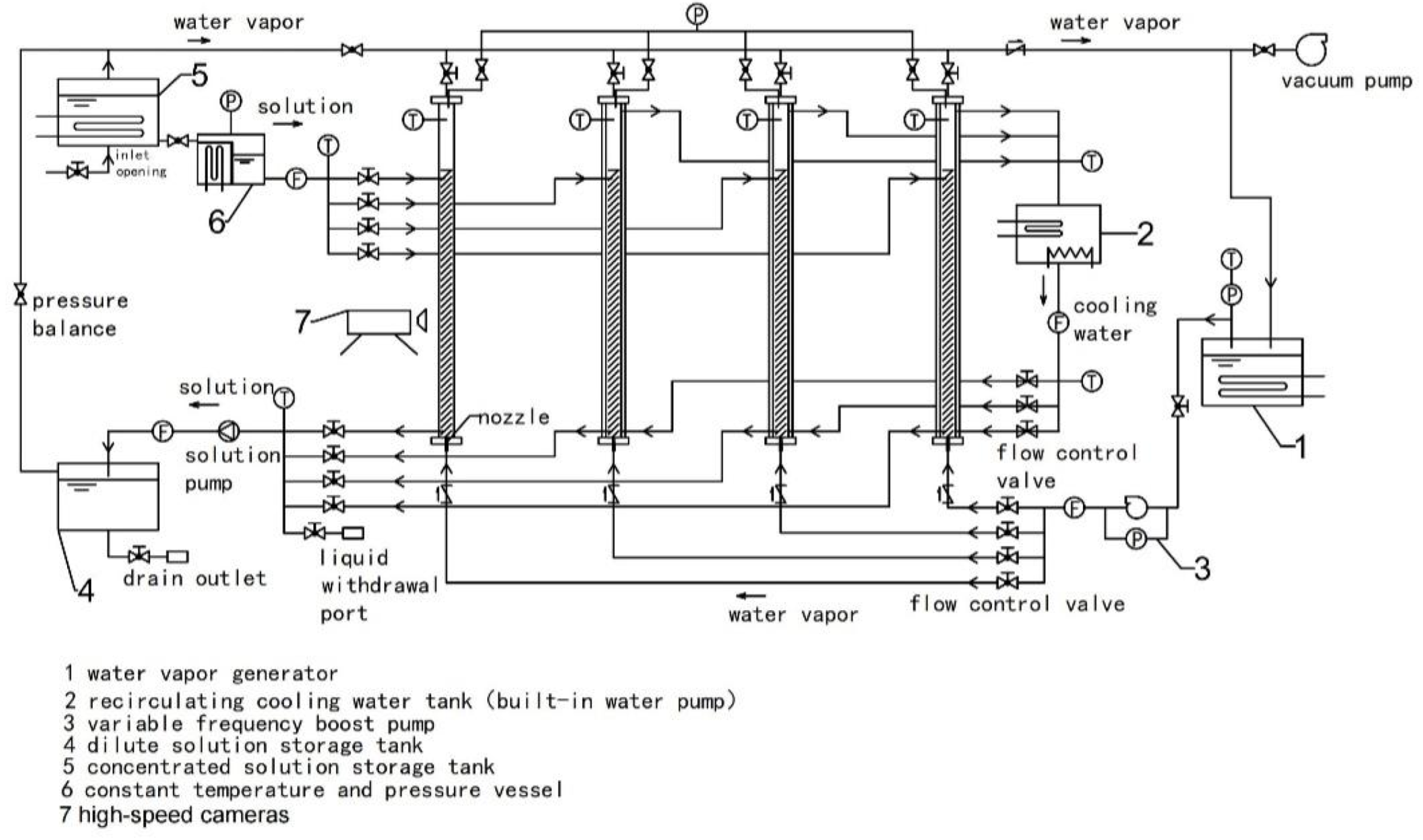
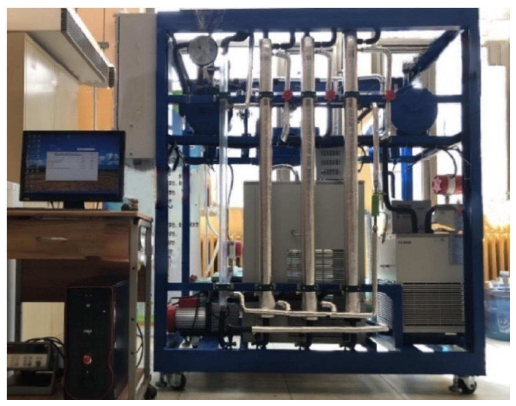
2.1. System Structure

The structural schematic diagram and physical layout of the experimental setup for investigating bubbling absorption and transport characteristics of lithium bromide solution in a vertical tube are presented in Figure 1 and Figure 2. The experimental device comprises five primary components: the steam system, solution system, cooling water system, bubble absorber, and experimental data testing and analysis system.
(1)
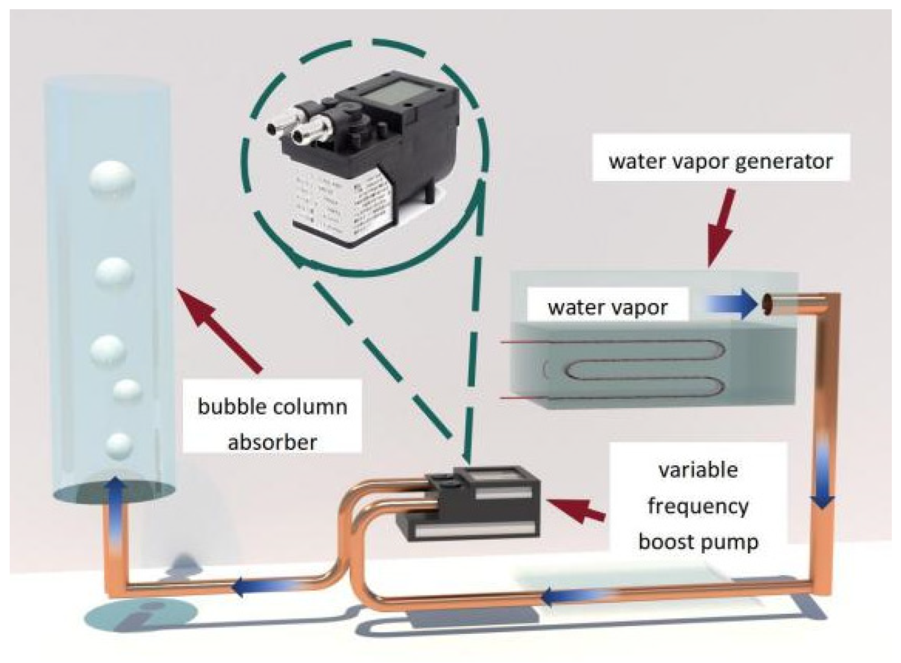
The steam pressurization system primarily consists of a variable frequency booster pump, vacuum pump, steam generator, flow control valve, and check valve. The system is utilized to provide the necessary steam for the experiment while ensuring a suitable flow rate. To overcome the resistance caused by hydraulic head and flow, the system employs a variable frequency booster pump to generate the required pressure for water vapor, thereby ensuring the generation and upward movement of bubbles, as depicted in Figure 3. The steam generator incorporates an electric heating function, enabling the heating, boiling, and vaporization of distilled water under low pressure, producing water vapor. The check valve serves as a precaution against liquid backflow and helps maintain pressure equilibrium within the system.
(2)
The solution system comprises several components: a concentrated solution storage tank, a dilute solution storage tank, a solution pump, a constant temperature and pressure tank, a flow control valve, and pipelines. These components are utilized for storing, generating, and circulating concentrated and dilute solutions, while ensuring the smooth absorption of the solution into the bubble absorber at a specific temperature. The lower part of the concentrated solution storage tank is equipped with an inlet to draw in the solution using the vacuum pressure of the system. The outlet is connected to the constant temperature and pressure tank, and a steam system is linked to the pipeline above. The constant temperature and pressure tank maintain a steady temperature and the pressure of the water vapor entering the bubble absorber.
(3)
The bubble absorber encompasses a visual bubble absorber, consisting of a cylindrical glass jacket and a high-speed camera, as well as a visual bubble absorber, constructed with a cylindrical double-layer copper jacket and a temperature sensor. The visual bubble absorber aids in determining the flow characteristics of bubbles during solution absorption, while the non-visual bubble absorber helps in assessing the heat and mass transfer properties. Both absorbers are connected to a sampling port for convenient testing of solution concentration.
(4)
The cooling water system comprises a constant temperature circulation water bath, a flow control valve, valves, and pipelines. The constant temperature circulation water bath supplies cooling water to the bubble absorber and acts as a consistent heat source for the concentrated solution storage tank.
(5)
The experimental data testing and analysis system incorporates various instruments, including thermocouples, pressure sensors, flow meters, density analyzers, high-speed cameras, data acquisition devices, and computers. The material parameters of the experimental setup are listed in Table 1, while the instrument parameters used are outlined in Table 2.

2.2. System Operation

(1) Decrease the internal pressure of the equipment to vacuum status. Prior to initiating the experiment, seal all valves connecting the system to the atmosphere (exhaust valve/inlet valve) and ensure internal communication by opening all valves within the system. Subsequently, utilize a vacuum pump to deplete the system and reach the desired vacuum level. Upon achieving the target vacuum, close the vacuum pump valve and power off the vacuum pump to maintain the system in a vacuum state. Utilize the system’s vacuum level to fill the solution storage tank with the required amount of liquid. Once the desired filling level is reached, close the inlet valve and repeat the vacuum process to eliminate any non-condensable gases.
(2) During the experiment, activate the circulation cooling water tank and regulate the flow rate and temperature of the cooling water within the outer pipe of the bubble absorber. Initiate the solution circulation pump to deliver the temperature-controlled concentrated lithium bromide solution into the inner tube of the bubble absorber. When the liquid column inside the bubble absorber reaches the desired height, open the flow control valve to allow the solution to flow back to the dilute solution storage tank from the bottom outlet. Start the steam generator and utilize a variable frequency booster pump to pressurize the water vapor within the system. The pressurized water vapor, guided by a nozzle into the bubble absorber, facilitates the absorption process. Adjust the flow control valve to manage the flow rate of the water vapor, with any unabsorbed vapor being returned to the steam generator via a one-way valve.
(3) During the visual experiment, once the bubble flow within the system stabilizes during the absorption process, employ a high-speed camera to capture bubble movement, size, absorption height, and velocity. After data capture, utilize image processing software for further analysis, applying correction factors to account for the actual bubble size based on a comparison between the actual nozzle size and its representation in the image. For the non-visual experiment, once the absorption operation stabilizes, utilize high-precision thermocouples, flow meters, pressure sensors, and density meters to measure critical thermodynamic parameters, including inlet and outlet temperatures, flow rates, and concentrations of cooling water and solution, as well as the pressure, temperature, and flow rate of the water vapor within the system. Finally, process the collected data using a data acquisition device.
(4) Upon completing the experiment, disconnect the power supply to the concentrated solution storage tank, steam generator, and circulating cooling water tank. Allow the system to equilibrate with ambient temperature before using the vacuum pump to evacuate it once more, ensuring it remains under negative pressure.

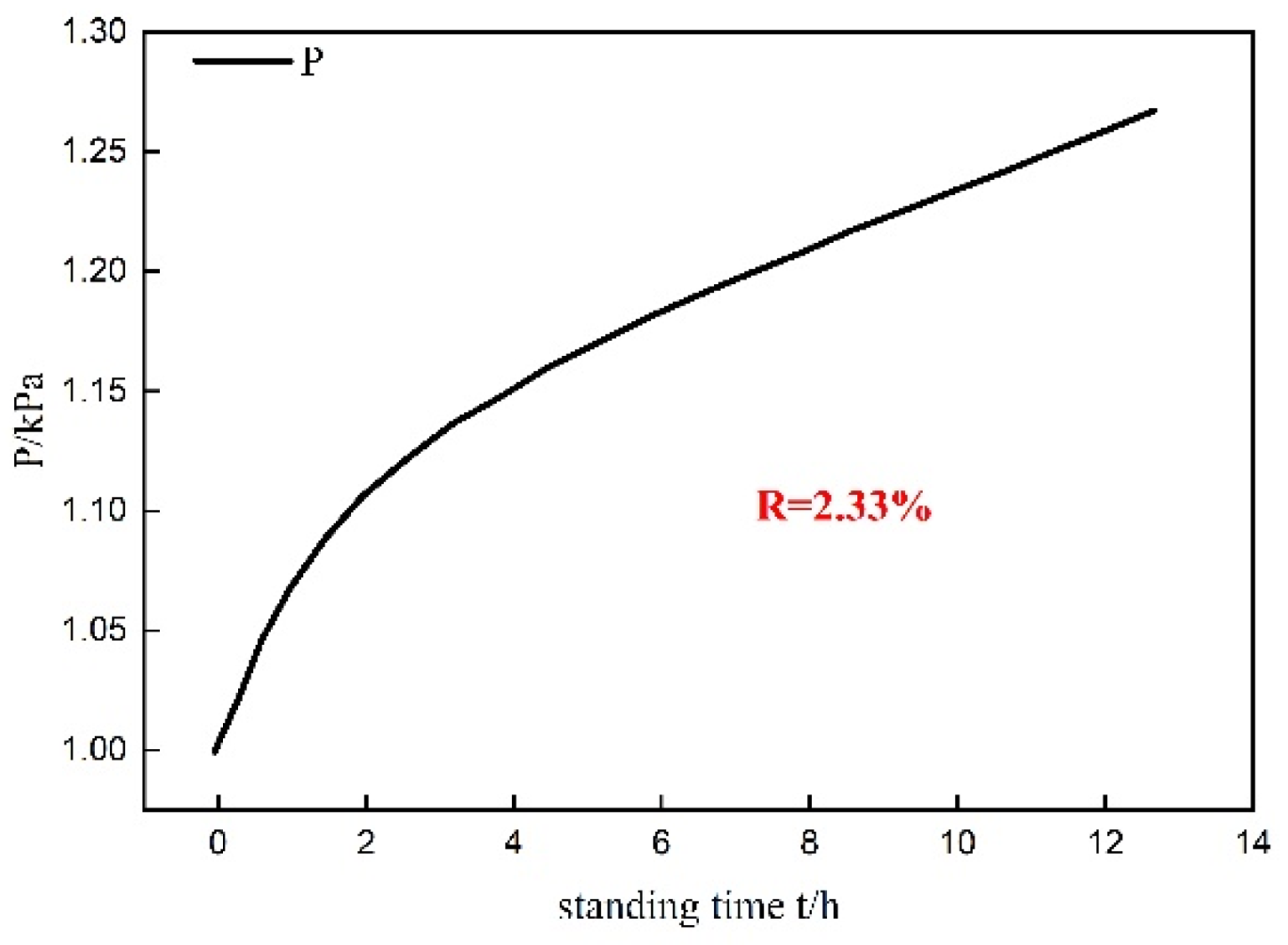
3. System Reliability

The reliability of the system’s vacuum sealing is of paramount importance, requiring a verification of its effectiveness. This study utilized an electronic halogen leak detector and soapy water to identify any leaks within the system. The system was then evacuated using a vacuum pump until the pressure reached 1 kPa. The vacuum rate was calculated using Equation (1).
R = P 1 P 0 T 1 T 0
where R represents the rate of increase of system vacuum degree, P 0 and P 1 denote the initial and final pressures measured by the system, Pa; and T 0 and T 1 represent the initial and final time measurements, h.
Presented in Figure 4, after 12 h of standing, the system’s pressure increased by 280 Pa, resulting in a vacuum increase rate of 2.33%.
Based on the ideal gas state equation, the gas leakage rate of the system was determined to be 2.4 mL/h, which is significantly lower than the allowable leakage rate of 6.5 mL/h prescribed by relevant standards in China. Consequently, the system demonstrates excellent airtightness.

4. System Accuracy Validation

To ascertain the reliability of the experimental setup, this study conducted experimental investigations on bubble flow, heat transfer, and energy conservation. Given the operating parameters of the heat pump, the steam temperature was fixed at 20 °C, with a saturation pressure of 2.338 kPa. Considering that the absorption pressure in the absorption heat pump system is approximately equivalent to the evaporation pressure, the absorption pressure in this experiment was set at 2.338 kPa. Due to the potential risk of supercooling crystallization in high-concentration lithium bromide solution, a solution concentration of 55% was selected for this study. The experimental operating conditions are enumerated in Table 3.

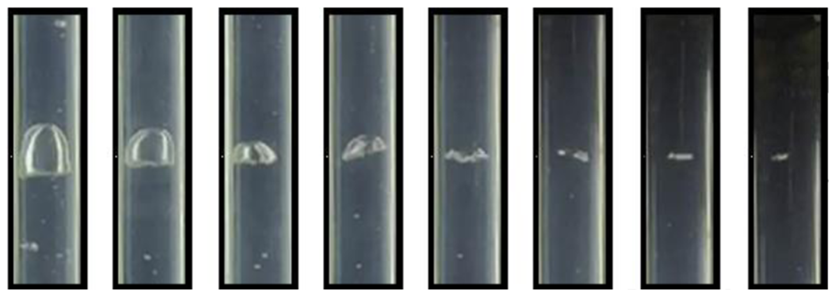
4.1. Bubble Flow Verification

A nozzle with a diameter of 4 mm was selected for the experiment to investigate the generation and rise of bubbles during the bubble absorption process, as depicted in Figure 5. The diameter in the figure mainly refers to the equivalent diameter, which means that the diameter of an imaginary perfect spherical bubble is equal to the bubble volume. In other words, it is the diameter of an imaginary sphere whose volume is equal to the volume of an actual bubble. The average diameter of a bubble is the arithmetic mean of the average diameter of the bubble during the generation stage, Taylor bubbles stage, and absorption stage. Upon pressurization, water vapor gradually formed small bubbles at the nozzle. As the bubble volume increased, they detached from the nozzle and entered the solution; the diameter range of bubbles was 4.2 mm to 7.8 mm, so their arithmetic mean was 5.45 mm during the generation stage. The bubbles in the solution were influenced by initial pressure and buoyancy, causing them to oscillate and rise. The smaller bubbles rapidly caught up with the preceding bubbles, leading to collision and coalescence, forming large bubbles with circular oscillating wave-like structures on the sides, known as Taylor bubbles. During this stage, the diameter range of bubbles was 7.8 mm to 25.88 mm, so their arithmetic mean was 16.84 mm. The large bubbles continued to rise until they reached the liquid surface, where they were squeezed and eventually ruptured, the diameter range of bubbles was 25.88 mm to 6.25 mm, so their arithmetic mean was 12.94 mm. The bubble generation, rise, collision, coalescence, and rupture behaviors observed in the bubble absorber were consistent with previous studies [6] on bubble flow. Therefore, the accuracy of the experimental setup was verified through the bubble flow experiment. However, there were differences in bubble morphology and size compared to the literature [6], as shown in Figure 6. This could be attributed to the experimental conditions being in a vacuum environment, which resulted in significant changes in the forces acting on the bubbles compared to those in atmospheric pressure.

4.2. Heat Transfer Verification

The initial temperature of the lithium bromide solution was set at 40 °C, while the initial temperature of the cooling water was 20 °C. Temperature measurements were taken for the solution outlet, concentration, and cooling water outlet at various nozzle sizes, and relative deviations were calculated. Figure 7 depicts the variations in the solution outlet temperature and cooling water outlet temperature with respect to nozzle size. The maximum relative deviation in the measurement of the solution outlet temperature was less than 0.08%, and for the cooling water outlet temperature, it was less than 0.02%. Figure 8 illustrates the variation of the solution outlet concentration with nozzle size, with a maximum relative deviation in the measurement of the solution outlet concentration of less than 0.01%. Therefore, the accuracy of the experimental setup was confirmed from the perspective of heat transfer.

4.3. Energy Conservation Verification

Based on the principle of energy conservation, this study conducted energy balance verification experiments on the lithium bromide solution side, steam side, and cooling water side. The heat input is balanced with the heat gain from the cooling water and the heat loss from the steam.
The heat exchange equations for the solution side:
Q s = m s ( h s , o u t h s , i n )
The heat exchange equations for the steam side:
Q a = m a ( h a , o u t h a , i n )
The heat exchange equation for the cooling water side:
Q w = c w m w ( t o u t t i n )
where Q s , Q a , and Q w are the heat exchange amounts for the solution, steam, and cooling water, respectively, J. m s , m a , and m w are the masses of the solution, steam, and cooling water, kg. h s , i n and h s , o u t are the enthalpies of the solution at the inlet and outlet, respectively, J/kg. h a , i n and h a , o u t and the enthalpies of the steam at the inlet and outlet, respectively, J/kg. c w is the specific heat capacity of the cooling water, J/(kg·K). t i n and t o u t are the inlet and outlet temperatures of the cooling water, K.
The heat loss of the system was calculated by utilizing the changes in enthalpy of the solution and steam, and was compared with the heat gained by the cooling water. As depicted in Figure 9 and Figure 10, by adjusting the inlet temperature of the lithium bromide solution within the range of 35–39 °C, the maximum energy balance error was 10.4 J. By varying the flow rate of the lithium bromide solution within the range of 10–50 L/h, the maximum energy balance error was 12.5 J. The experimental errors in the system energy balance verification were minimal. Therefore, the accuracy of the experimental setup was ascertained from the perspective of energy balance.

5. Conclusions

This study introduces an experimental setup for enhancing solution bubble absorption by employing a variable frequency booster pump. The pump generates the driving force necessary to overcome the height potential difference and flow resistance of the refrigerant vapor. The reliability and accuracy of the setup were validated through experiments on vacuum maintenance, bubble flow, and energy balance. The main findings are as follows:
(1) Under negative pressure conditions, the applied boosting technique successfully facilitated bubble absorption of water vapor in the solution;
(2) The vacuum rate of the experimental setup was 2.33%, and the system gas leakage rate was 2.4 mL/h, indicating good air tightness and reliable operation of the experimental setup;
(3) The observed generation, rise, collision, coalescence, and rupture behavior of bubbles observed during the experiment were consistent with the literature on bubble flow. At an absorption pressure of 2.338 kPa and a steam temperature of 20 °C, the maximum relative deviations in the measured values of the solution outlet temperature and the cooling water outlet temperature were 0.08% and 0.02%, respectively. The maximum relative deviation in the measured solution outlet concentration was 0.01%;
(4) Based on the principle of energy conservation, the energy balance verification for different solution inlet temperatures and solution flow rates yielded maximum errors of 10.4 J and 12.5 J, respectively. These results demonstrate the high accuracy of the experimental setup.
In order to optimize the experimental setup for increased efficiency and reliability, studies, including the heat and mass transfer capacity of the bubbling absorber, the influence of structural parameters, physical parameters, and control parameters on the heat and mass transfer of the bubbling absorber, the heat and mass transfer mechanism of the bubbling absorber, the optimal combination of parameters of the experimental setup, the heat transfer coefficient and mass transfer coefficient of the bubbling absorber, will be carried out. The effect of nozzle diameter on bubble size, and the conservation of mass and mass transfer characteristics for the bubble absorption system are important. Therefore, the relationship between bubble size and nozzle diameter, mass conservation, and the influence mechanism of different factors on heat and mass transfer in the bubble absorption process will also be studied in future work.

Author Contributions

Methodology, G.W., J.L. and Y.X.; Validation, J.G.; Investigation, X.Z.; Writing—original draft, J.G.; Writing—review & editing, G.W., X.C. and X.L.; Supervision, G.W.; Project administration, G.W. All authors have read and agreed to the published version of the manuscript.

Funding

This work was supported by the National Natural Science Foundation of China [grant numbers 52006008] and the financial support of the Beijing University of Civil Engineering and Architecture-Basic Research Business Fund for Municipal Universities (No. X23029).

Data Availability Statement

The data that support the findings of this study are available from the corresponding author upon reasonable request.

Conflicts of Interest

Author Gang Wang was employed by the company Jiangsu Baixue Electrical Appliances Co., Ltd., Xuejing Zhang was employed by the company CLP Systems Construction Engineering Co., Ltd. The remaining authors declare that the research was conducted in the absence of any commercial or financial relation-ships that could be construed as a potential conflict of interest.

References

  1. Li, S.; Inayat, M.; Järvinen, M. Steam Gasification of Polyethylene Terephthalate (PET) with CaO in a Bubbling Fluidized Bed Gasifier for Enriching H2 in Syngas with Response Surface Methodology (RSM). Appl. Energy 2023, 348, 121536. [Google Scholar] [CrossRef]
  2. Ibarra-Bahena, J.; Romero, R. Performance of Different Experimental Absorber Designs in Absorption Heat Pump Cycle Technologies: A Review. Energies 2014, 7, 751–766. [Google Scholar] [CrossRef]
  3. Jiang, M.; Xu, S.; Wu, X. Numerical Simulation and Experiment for R124-DMAC Bubble Absorption Process in a Vertical Tubular Absorber. Int. J. Therm. Sci. 2019, 138, 124–133. [Google Scholar] [CrossRef]
  4. Yang, L.; Du, K.; Zhang, X. Influence Factors on Thermal Conductivity of Ammonia-Water Nanofluids. J. Cent. South Univ. Technol. 2012, 19, 1622–1628. [Google Scholar] [CrossRef]
  5. Kemoun, A.; Cheng Ong, B.; Gupta, P.; Al-Dahhan, M.H.; Dudukovic, M.P. Gas Holdup in Bubble Columns at Elevated Pressure via Computed Tomography. Int. J. Multiph. Flow 2001, 27, 929–946. [Google Scholar] [CrossRef]
  6. Wu, X.; Liu, J.; Xu, S.; Wang, W. Effect of Vibration Parameters on the Bubble Absorption Characteristics of Working Fluids R134a–DMAC in a Vertical Tube. Int. J. Refrig. 2019, 99, 234–242. [Google Scholar] [CrossRef]
  7. Kang, Y.T.; Nagano, T.; Kashiwagi, T. Visualization of Bubble Behavior and Bubble Diameter Correlation for NH3–H2O Bubble Absorption. Int. J. Refrig. 2002, 25, 127–135. [Google Scholar] [CrossRef]
  8. Kim, H.Y.; Saha, B.B.; Koyama, S. Development of a Slug Flow Absorber Working with Ammonia–Water Mixture: Part II—Data Reduction Model for Local Heat and Mass Transfer Characterization. Int. J. Refrig. 2003, 26, 698–706. [Google Scholar] [CrossRef]
  9. Li, L.; Kang, Y.T. Effects of Bubble Coalescence and Breakup on CO2 Absorption Performance in Nanoabsorbents. J. CO2 Util. 2020, 39, 101170. [Google Scholar] [CrossRef]
  10. Li, L.; Kang, Y.T. Bubble Behaviors and CO2 Absorption Characteristics in Nanoabsorbents. J. CO2 Util. 2019, 33, 488–499. [Google Scholar] [CrossRef]
  11. Roy, S. Catalytic Wet Air Oxidation of Oxalic Acid Using Platinum Catalysts in Bubble Column Reactor: A Review. J. Eng. Sci. Technol. Rev. 2010, 3, 95–107. [Google Scholar] [CrossRef]
  12. Xu, S.; Jiang, M.; Hu, J.; Wu, X.; Wang, W. Visual Experimental Research on Bubble Absorption in a Vertical Tube with R124–DMAC Working Pair. Exp. Therm. Fluid Sci. 2016, 74, 1–10. [Google Scholar] [CrossRef]
  13. Kang, Y.T.; Nagano, T.; Kashiwagi, T. Mass Transfer Correlation of NH3–H2O Bubble Absorption. Int. J. Refrig. 2002, 25, 878–886. [Google Scholar] [CrossRef]
  14. Jiang, M.; Xu, S.; Wu, X.; Wang, W. Heat and Mass Transfer Characteristics of R124-DMAC Bubble Absorption in a Vertical Tube Absorber. Exp. Therm. Fluid Sci. 2017, 81, 466–474. [Google Scholar] [CrossRef]
  15. Jiang, M.; Xu, S.; Wu, X.; Hu, J.; Wang, W. Visual Experimental Research on the Effect of Nozzle Orifice Structure on R124–DMAC Absorption Process in a Vertical Bubble Tube. Int. J. Refrig. 2016, 68, 107–117. [Google Scholar] [CrossRef]
  16. Kim, H.Y.; Saha, B.B.; Koyama, S. Development of a Slug Flow Absorber Working with Ammonia-Water Mixture: Part I—Flow Characterization and Experimental Investigation. Int. J. Refrig. 2003, 26, 508–515. [Google Scholar] [CrossRef]
  17. Kim, J.-K.; Jung, J.Y.; Kang, Y.T. The Effect of Nano-Particles on the Bubble Absorption Performance in a Binary Nanofluid. Int. J. Refrig. 2006, 29, 22–29. [Google Scholar] [CrossRef]
  18. Wu, W.-D.; Liu, G.; Chen, S.-X.; Zhang, H. Nanoferrofluid Addition Enhances Ammonia/Water Bubble Absorption in an External Magnetic Field. Energy Build. 2013, 57, 268–277. [Google Scholar] [CrossRef]
  19. Donnellan, P.; Cronin, K.; Lee, W.; Duggan, S.; Byrne, E. Absorption of Steam Bubbles in Lithium Bromide Solution. Chem. Eng. Sci. 2014, 119, 10–21. [Google Scholar] [CrossRef]
  20. Ayou, D.S.; Bruno, J.C.; Coronas, A. Integration of a Mechanical and Thermal Compressor Booster in Combined Absorption Power and Refrigeration Cycles. Energy 2017, 135, 327–341. [Google Scholar] [CrossRef]
  21. Xie, G.; Wu, Q.; Fa, X.; Zhang, L.; Bansal, P. A Novel Lithium Bromide Absorption Chiller with Enhanced Absorption Pressure. Appl. Therm. Eng. 2012, 38, 1–6. [Google Scholar] [CrossRef]
  22. Khalili, S.; Garousi Farshi, L. Design and Performance Evaluation of a Double Ejector Boosted Multi-Pressure Level Absorption Cycle for Refrigeration. Sustain. Energy Technol. Assess. 2020, 42, 100836. [Google Scholar] [CrossRef]
  23. Lee, J.B.; Derome, D.; Carmeliet, J. Drop Impact on Natural Porous Stones. J. Colloid Interface Sci. 2016, 469, 147–156. [Google Scholar] [CrossRef]
  24. Kabir, H.; Garg, N. Rapid Prediction of Cementitious Initial Sorptivity via Surface Wettability. NPJ Mater. Degrad. 2023, 7, 52. [Google Scholar] [CrossRef]
Figure 1. Structure diagram of bubble absorption experimental device for solution.
Buildings 14 01685 g001
Figure 2. Solution bubble absorption experimental device.
Buildings 14 01685 g002
Figure 3. Schematic diagram of steam pressurization system.
Buildings 14 01685 g003
Figure 4. Curve of system vacuum degree with time.
Buildings 14 01685 g004
Figure 5. Bubble generation, rise, burst stage. (a,b) Bubble generation stage, (ce) bubble rise stage, (fi) bubble burst stage.
Buildings 14 01685 g005
Figure 6. Bubble visualization experimental results [6].
Buildings 14 01685 g006
Figure 7. Solution outlet temperature and cooling water outlet temperature.
Buildings 14 01685 g007
Figure 8. Solution outlet concentration.
Buildings 14 01685 g008
Figure 9. Energy balance error of different solution inlet temperature.
Buildings 14 01685 g009
Figure 10. Energy balance error of different solution flow.
Buildings 14 01685 g010
Table 1. Bubble absorber material table.
InstrumentModel NumberRangePrecisionRemark
Solution pumpAQG-24-silicone tube480 mL/min2%--
Variable frequency booster pumpV60L-JJ-24V18 L/min--ΔP ≥ −88 kPa
Vacuum pumpROAIRVAC9.04 L----
Thermal insulation materialPolyethylene insulation material------
Bubble absorberVisualizationMaterial: glass; nozzle diameter: 4 mm; pipe diameter: 30 mm; pipe length: 1.2 m
Non-visualizationMaterial: copper; nozzle diameter: 2 mm, 4 mm, 6 mm; inner pipe diameter: 30 mm; outer pipe diameter: 40 mm; pipe length: 1.2 m
Table 2. Instrumentation parameter table.
InstrumentModel NumberRangePrecisionRemark
Solution flowmeterNKGF02F1L10.6~6 L/H±0.5%FS--
Gas flowmeterMF50000~50 L/min±1.5%FS--
Cooling water flowmeterNKGF02F1L10.6~6 L/H±0.5%FS--
Pressure sensorPT-8303B0~150 kPa±0.5%FS--
Thermoelectric coupleSWT-KPS-NI600-T1-20-2000−200~300 °C±0.5 °C--
Densitometer KEM WBA-5050~3 g/cm3±0.00005 g/cm3--
High speed cameraPhantom Ametek V211------
Data acquisition instrumentKeysight 34901A------
Table 3. Experimental conditions parameters.
Experimental Conditions ParametersNumerical Value
LiquorInlet temperature35~40 °C
Inlet flow rate10~50 L/h
Cooling waterInlet temperature20 °C
Inlet flow rate0.0143 L/h
OtherNozzle diameter2~6 mm
Steam inlet velocity2 m/s
Pressure ratio1.1
Disclaimer/Publisher’s Note: The statements, opinions and data contained in all publications are solely those of the individual author(s) and contributor(s) and not of MDPI and/or the editor(s). MDPI and/or the editor(s) disclaim responsibility for any injury to people or property resulting from any ideas, methods, instructions or products referred to in the content.

