Article

Geometric Design Methodology for Deployable Self-Locking Semicylindrical Structures

1
School of Civil Engineering, Shaanxi Polytechnic Institute, Xianyang 712000, China
2
College of Civil Engineering, Xi’an University of Architecture and Technology, Xi’an 710055, China
*
Author to whom correspondence should be addressed.
Buildings 2024, 14(6), 1690; https://doi.org/10.3390/buildings14061690
Submission received: 6 April 2024 / Revised: 29 May 2024 / Accepted: 4 June 2024 / Published: 6 June 2024
(This article belongs to the Section Building Structures)

Abstract

:
Due to their unique bistable characteristics, deployable self-locking structures are suitable for many engineering fields. Without changing the geometrical composition, such structures can be unfolded and locked solely by the elastic deformation of materials. However, their further applications are hampered by the lack of simple and systematic geometric design methodologies that consider arbitrary structural curvature profiles. This paper proposes such a methodology for double-layer semicylindrical grid structures to simplify their cumbersome geometric design. The proposed methodology takes joint sizes into account to ensure that the design results can be applied to actual projects without further adjustments. By introducing symmetry into the structural units (SUs) and selecting reasonable geometric parameters that describe the structural side elevation profile, a concise set of simultaneous nonlinear geometric constraint equations is established, the solution of which provides the geometric parameter values of the grid shape. On this basis, the remaining geometric parameter values, i.e., the geometric parameter values of the inner scissor-like elements (SLEs) of each SU, can be achieved from the equations derived from general SLEs. Design examples and the assembled physical grid structure indicate the feasibility and wide applicability of the proposed geometric design methodology.

1. Introduction

Since ancient times, the concepts of deployability and foldability have dramatically enhanced people’s lives. Naturally, such concepts have also been introduced into the design of modern structures and mechanisms. From the mobile exhibition pavilion, mobile theater [1], and deployable swimming pool cover [2] to the retractable roof (e.g., [3,4]) and space truss (e.g., [5,6]), the applications of deployable structures have experienced remarkable development. In conjunction with their applications, theoretical analyses of these concepts have made enormous progress. Many studies have been conducted to summarize the geometrical principles of developable structural systems [7,8,9,10], to discuss their structural capabilities under completely expanded configurations bearing loads [11,12,13], and to probe the inherent regularities of their intermediate configurations during mechanical motions [14,15,16,17]. In addition, the utilization of new materials also provides deployable structures with unique characteristics that enable them to operate in special environments [18,19], thereby facilitating an extensive imagination space for the further development of deployable structural forms.
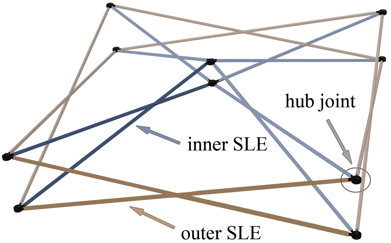
Deployable structures have been the subject of increasing attention as a result of their many virtues, such as their industrial prefabrication, their reusability, and their rapid construction time [20]. As one type of deployable scissor structure (e.g., [21,22]) composed of scissor-like elements (SLEs) (Figure 1), the deployable self-locking structure can support its own weight and bear a certain external load without imposing any geometric constraints when it is fully deployed. It is also bistable, that is, it is free of stress when either completely folded or completely expanded, which constitutes the basis for its geometric design [23,24]. With these characteristics, the self-locking structure possesses much more excellent properties than traditional structures, such as faster unfolding and higher reliability. Therefore, the self-locking structure, which was invented by Zeigler [25], has been applied in a wide variety of fields. Without changing the geometrical composition, such structure can be unfolded solely by the bending elastic deformation of components [26].
Among the many configurations of self-locking deployable grid structures, the semicylindrical shell is the most widely used structural style for temporary buildings (Figure 2). The double-layer semicylindrical grid structure is generally composed of hexahedral structural units (SUs, Figure 3), and each independent SU is characterized by the abovementioned integral grid structure. To further enhance the self-stabilizing capability of the entire grid after deployment, the studies focusing on SU configuration improvements are still in progress [27]. Correspondingly, some progress has been made in the research on more refined mechanical models [16,22,28]. Furthermore, in the direction of lightweighting semicylindrical grid structures, the reciprocal linkages proposed by Pérez-Valcárcel et al. [29,30] are expected to be a promising research direction.
The spatial configurations of all deployable grid structures have a vital influence on their structural performance; therefore, the geometric design of the spatial configuration is critical [31,32,33]. To reduce the design workload for grid structures with array characteristics or with complex spatial configurations, the geometries of repeatable parts and detachable simple parts can be separately designed first. Then, the final grid structure can be obtained by sequentially assembling the divided parts. Of course, this method of first designing each part separately and then assembling the whole structure also provides a way for effectively diversifying the types of deployable structures [34]. In particular, the member lengths of the SLEs in each assembled structure must meet the foldability conditions of the overall grid structure to ensure that the structure can fold smoothly (Figure 1). In actual engineering endeavors, most scissor structures are usually flat plates (e.g., [35,36]) or shell surfaces with a constant curvature profile (e.g., [2]). Unfortunately, further applications of semicylindrical deployable grid structures are hindered by the absence of a geometric design methodology that permits an arbitrary curvature profile. To solve this problem, researchers have developed their systematic geometric design methodologies by assuming some approximate geometric constraints or by not fully considering the hub sizes [37]. However, these methodologies require a large number of geometric parameters and the solution of complicated nonlinear equations, and thus are not very convenient for design purposes or for engineering applications.
Therefore, this paper proposes a new methodology for self-locking deployable semicylindrical structures. Compared to previous work (e.g., [37]), this approach does not require the introduction of the algebraic equation as a geometric constraint on the side elevation profile of the shell surface. There is also no need to assume approximate dimensions of the components, which thereby introduce additional geometrical incompatibilities, which would result in the grid structure failing to reach a minimum volume after folding. Rather, the proposed method first establishes the geometric constraint equations used to describe the side elevation profile by selecting appropriate length and angle parameters and then obtains the geometric parameter values of the shape. Combined with the equations derived from general SLEs, the geometric parameter values for the inner SLEs of each SU are obtained, after which the structural geometric design can finally be completed. Obviously, this approach considers the inner and outer SLEs of the SU separately, and thus, fewer coupling equations are required, thereby improving the calculation efficiency.
Moreover, the previous methods integrate the geometrical relationships of adjacent inner and outer SLEs into a single unfolded plan view, which is strictly only applicable to the computation of regular prismatic units in some special structures (e.g., [16,23]). In contrast, the method proposed in this paper considers the universal geometrical relationships of pairs of bars in SUs in three-dimensional space, making it more widely applicable. In addition, the introduction of symmetry not only benefits the design process but also facilitates the assembly of the structure. Therefore, the proposed methodology establishes the SU as a configuration with symmetrical characteristics and takes the joint sizes accurately into account so that the design results can be applied to actual engineering. The final examples and the model produced herein indicate the feasibility and broad applicability of the geometric design methodology for double-layer semicylindrical grid structures.

2. Outline of a Double-Layer Semicylindrical Grid Structure with Ideal Joints

2.1. Construction of the Semicylindrical Grid Structure Configuration

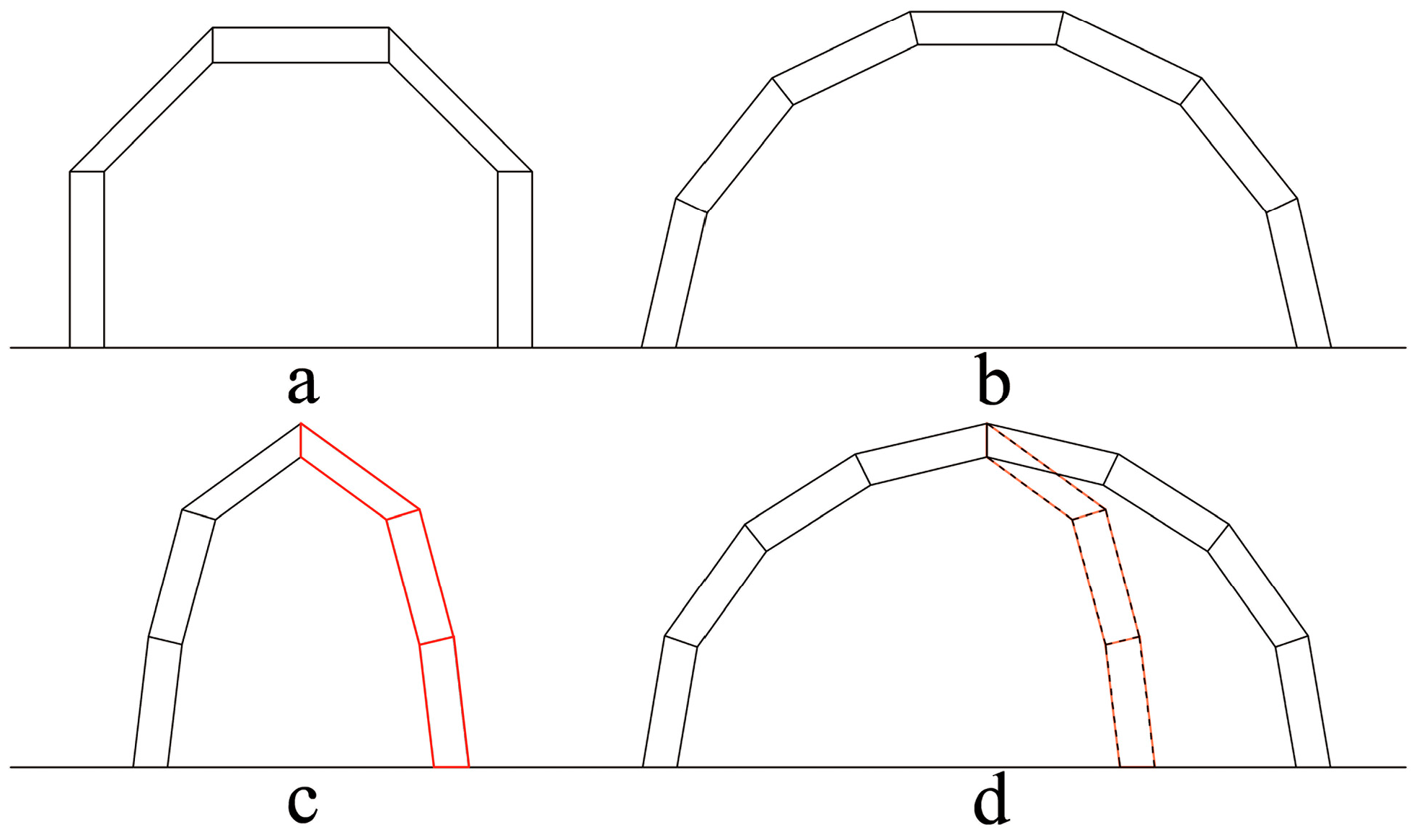
The derivation presented in this section is based on the assumption that the grid joints are ideal joints, which are spatially articulated nodes with a size of zero. The construction of the double-layer semicylindrical grid configuration is illustrated in Figure 4. This derivation will also provide the basis for the mathematical description of the geometric configuration throughout this paper.
An auxiliary global right-handed coordinate system is first established for convenience. Then, the projection curve of the structural outer layer surface with arbitrary curvature is plotted in the XOZ-plane, as shown in Figure 4a. The axis of symmetry of the surface is the Z-axis. One point of intersection between this curve and the X-axis is A1. S denotes the structural span. Similarly, the inner layer projection curve is plotted with identical curvature. The corresponding intersection point is denoted as a1, as shown in Figure 4b. The parameter t represents the structural thickness, which is the distance between A1 and a1.
This pair of curves translates into a distance of W along the Y-axis (Figure 4c). Accordingly, the structural upper layer surface is obtained, where B1 and b1 are the corresponding points after translation. The inner layer surface is formed by reducing the length of a1b1 symmetrically (Figure 4d), and d denotes the reduced length of the two sides. Combined with the lengths of the bars that will be derived in the following sections, the peripheral SLEs of the structure are inserted into the anticipated SU shapes (Figure 4e). Finally, the inner SLEs are inserted into the corresponding Sus (Figure 4f). This step also marks the completion of the construction of the structural configuration.

2.2. Selection of Geometric Parameters

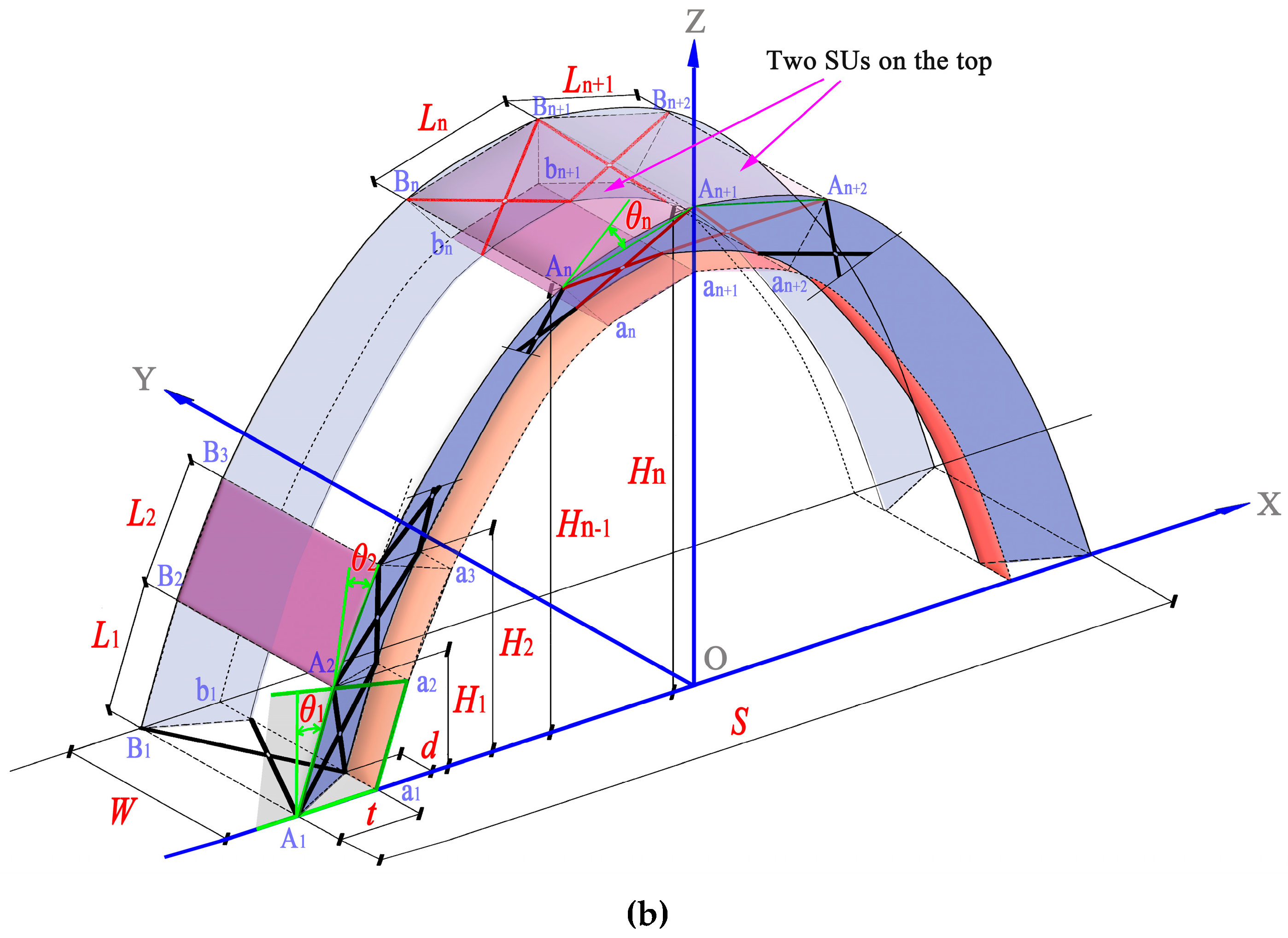
Based on whether an independent SU exists at the top of the grid, two types of configurations for the semicylindrical grid structure are given to facilitate the geometric design, as shown in Figure 5. In the geometric design, parameters are needed to establish a mathematical expression that describes the structural spatial configuration, and then a system of equations consisting of multiple expressions can be used to solve for the values of these parameters. However, there is a large number of geometric parameters suitable for establishing the above equations; therefore, to meet the needs of building functions and ensure the convenience of subsequent calculations, these parameters need to be reasonably selected. Obviously, for the purpose of effectively guaranteeing the spatial size of the structure, the parameters describing the geometric characteristics of the overall structure, including the net height, the lateral span, the façade length and the structural thickness, are suitable parameters for the geometric equations. In addition, to describe the changes in the curvature of the outer structural surface, angle variables reflecting the upper surfaces of the Sus should be selected as geometric parameters. Accordingly, the projected lengths of all Sus onto the side elevation profile of the structure can be selected as other parameters.
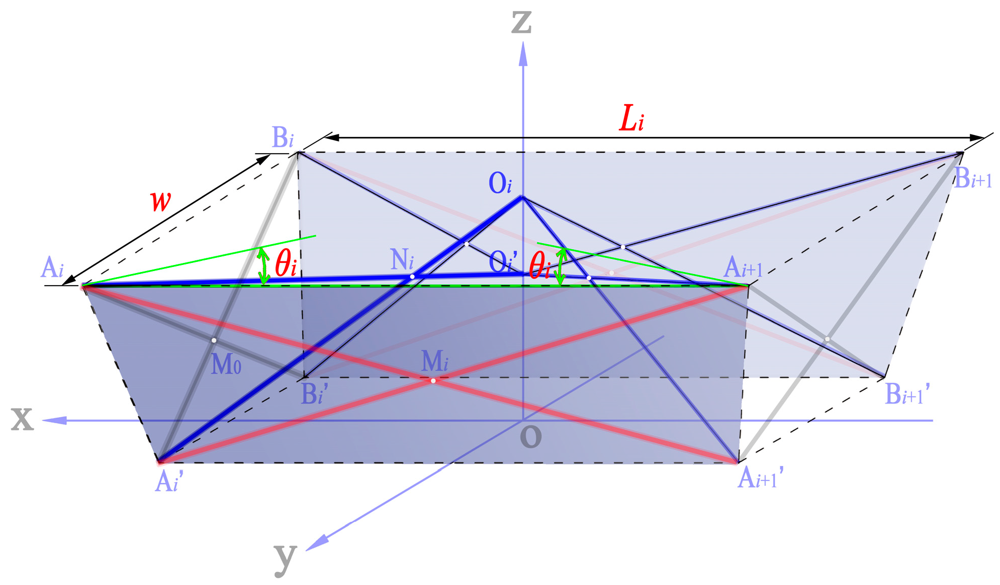
Allowing for the symmetry of a semicylinder, only one half-span arch is considered. The number of SUs constituting the half-span structure is n. Each geometric parameter is marked in Figure 5. Ai and Bi (i = 1, 2,…, n + 1) represent the lateral vertexes of the unit top rectangles in the upper layer, while Ai’ and Bi’ (i = 1, 2,…, n + 1) represent the vertexes of the bottom rectangles in the inner layer, refer to the example in Figure 6. ai is the corresponding projection of Ai’. Li (i = 1, 2,…, n) is the transverse length of the i-th unit. Hi (i = 1, 2,…, n) is the height of Ai+1. W denotes the overall width of the structure. In each SU (e.g., Figure 6), there are two planes of symmetry: the xoz-plane and the yoz-plane. In addition, the xoz-plane is parallel to the XOZ-plane in the global coordinate system. The xoy-plane coincides with the bottom surface of the SU Ai’Bi’Bi+1’Ai+1’ and is parallel to the upper surface AiBiBi+1Ai+1. For convenience, the variable representing the angle between the line AiAi+1 and the perpendicular line of Aiai in the global XOZ-plane is defined as θi (i = 1, 2,…, n).

2.3. Mathematical Descriptions of the Structural Profile

Known quantities should be presupposed based on the unique shape requirements. Assume that Hi, S, W, t, and d are known, for instance, and assume that Li and θi are the unknown quantities. According to the geometric constraints on the side elevation profile of the structure as well as the symmetry of each planar trapezoid Aiaiai+1Ai+1, the relationship of θi can be described as:
2 i = 1 n 1 θ i + α θ n = π / 2
where α is the selection coefficient. If structural configuration 1 is being referenced, α = 1; otherwise, α = 2. Because the SU has symmetrical characteristics and n ≥ 1, each angle parameter should meet the following constraint:
0 θ i π / 4
Furthermore, all the joint heights in the two configurations can be represented in a unified form:
k = 1 s L k cos ( 2 i = 1 k 1 θ i + θ k ) = H s ,   s = 1 , 2 , , n
For the present structural model, the height of each joint should vary between the following limits:
L 2 d 2 / 2 t 2 / 4 + t / 2 H s H s + 1 L 2 d 2 + s L 2 d 2 t 2 ,   s = 1 , 2 , , n 1
where L’ will be derived below to indicate the member length of the outer SLEs. The structural span can be denoted as follows:
k = 1 n L k sin ( 2 i = 1 k 1 θ i + θ k ) β 2 L n = S / 2
where β is the selection coefficient. If structural configuration 1 is being referenced, β = 1; otherwise, β = 0. In addition, S should be selected within a certain range:
t S / 2 L 2 d 2 / 2 t 2 / 4 + t / 2 + n 1 β / 2 L 2 d 2 t 2

2.4. Geometric Constraints on the Member Lengths of the SU

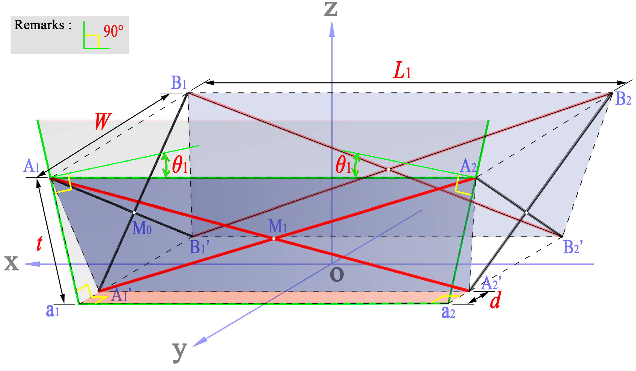
Consider the first SU separately (Figure 6). M0 and M1 are the pivots of the unit lateral trapezoids A1A1’B1’B1 and A1A1’A2’A2, respectively. Four equations exist between the member lengths simultaneously:
L A 1 M 0 = L B 1 M 0 ,   L A 1 M 0 = L B 1 M 0 ;   L A 1 M 1 = L A 2 M 1 ,   L A 1 M 1 = L A 2 M 1
The subscript refers to the line between two nodes. With the following foldability constraint:
L A 1 M 0 + L A 1 M 0 = L A 1 M 1 + L A 1 M 1
the following can be derived:
L A 1 B 1 = L A 1 A 2 = L
In other words, the members in the outer SLEs have the same length. This conclusion is also applicable to the other units. Since the Sus are connected by the same side face, the members in the outer SLEs of the overall structure also have the same length. In the A1A1’B1’B1 plane:
L = ( W d ) 2 + t 2
In the A1a1a2A2 plane, the explicit expression for the unit upper side length is as follows:
L 1 = ( L 2 d 2 ) ( t cos θ 1 ) 2 + t sin θ 1
Similar conclusions can be extrapolated for the other units:
L i = ( L 2 d 2 ) ( t cos θ i ) 2 + t sin θ i ,   i = 1 , 2 , , n
This equation also reveals the corresponding relationship between Li and θi in one SU.

2.5. Geometric Constraint Equations Describing the Structural Profile

From the derivation in the previous subsection, all the geometric parameters that determine the side elevation profile of the half-span structure can be expressed by the parameter Li and the parameter θi (i = 1, 2,…, n). Obviously, the final set of geometric constraint equations should have 2n unknown parameters, and 2n equations are needed for these unknown quantities.
First, the overall configuration of the double-layer semicylindrical grid structure requires that Equation (1) must be established. Second, the structural characteristics of each SU also require that Equation (12) must be established, where the number of equations is n. Finally, since the rise–span ratio has a great influence on the arch carrying capacity after the structure is fully deployed, Equation (5) for the structural span and the equation for the top joint height, that is, the equation when s = n in Equation (3), should be satisfied. At this point, n-3 equations are still required, and the corresponding number of equations should be selected in Equation (3) according to the needs of building functions to obtain the unique solution to the equations. From the above, the required number of equations is n ≥ 3. When n < 3, one of the structural spans and the top joint height is preferred as the control parameter. Due to the nonlinear characteristics of these equations, a numerical algorithm such as the quasi-Newton method can be used to solve them.

3. Pivot Endpoint Positions on the SLEs

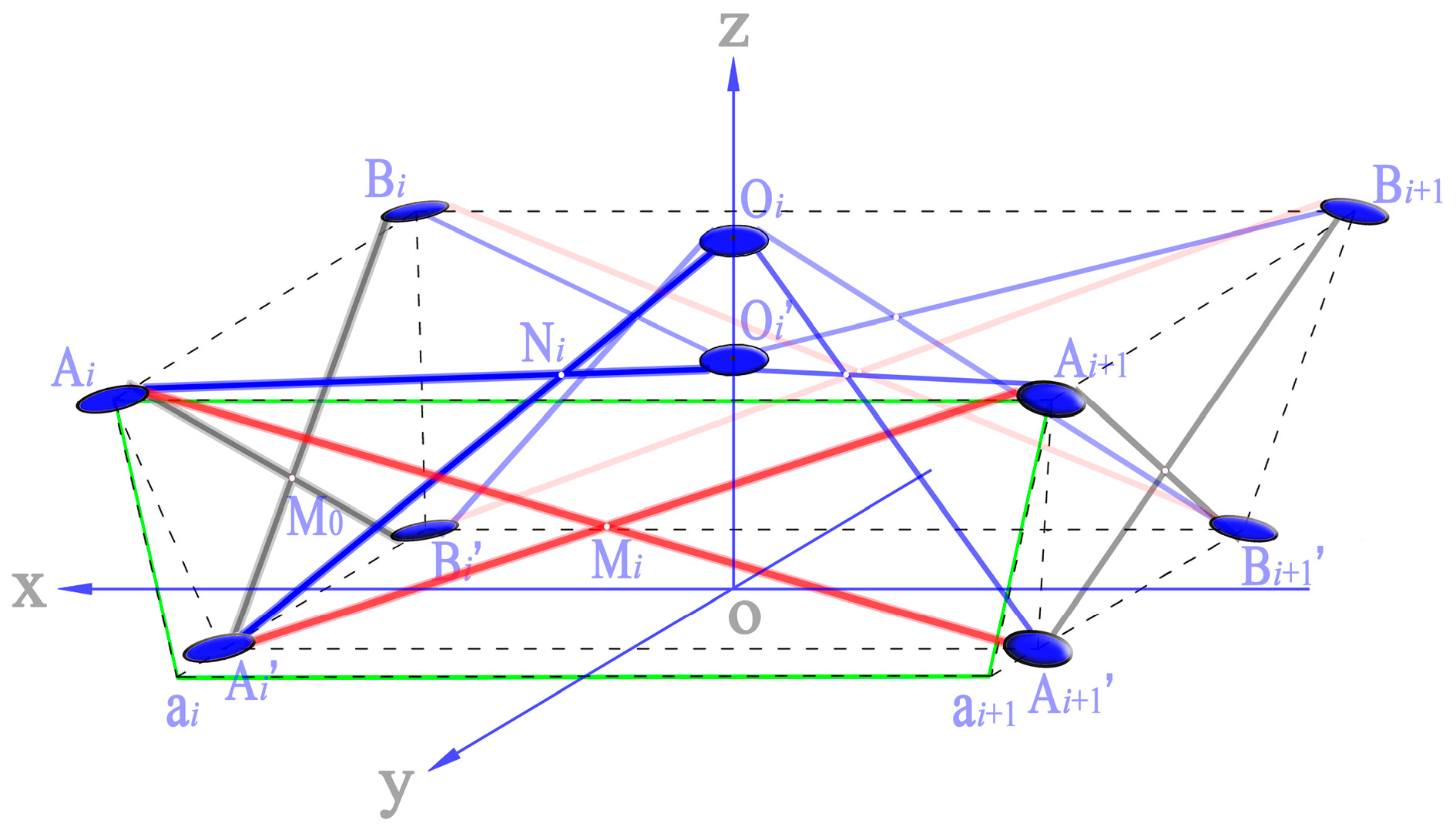
For the geometric design of a grid structure comprising SLEs, in addition to the required length of each member, it is also necessary to obtain the pivot endpoint positions on the SLEs. As shown in the previous sections, concise expressions can be obtained by introducing symmetrical properties into the structural configuration. Similar effects can be achieved for the expressions used to obtain the pivot endpoint positions. The general formation of a hexahedral SU is illustrated in Figure 7. Oi is the upper terminal node of the inner SLE on the z-axis, and Oi’ is the lower terminal node. M0 and Mi denote the pivots of AiAi’Bi’Bi and AiAi’Ai+1’Ai+1, respectively. Ni is the pivot of the inner SLE consisting of the members AiOi’ and Ai’Oi. The variable w representing the unit width is equal to the structural width W. Due to the symmetrical nature of the SU, the number of unknown SLEs has changed from eight pairs to three pairs (marked with different colored bold lines in Figure 7).

3.1. Outer SLEs of the SU

Consider the lateral face Ai’AiBiBi’ separately (Figure 8), where M0’ is the projection point of pivot M0 onto the side Ai’Bi’. The distances between Ai and M0, M0 and Bi’, and Ai’ and Bi’ are denoted as L01, L02, and L0, respectively. Accordingly, the following equations can be obtained:
L 02 = L 0 / 2 w 2 d × L
L 01 = L L 02
where L 0 = w 2 d .
Then, consider the lateral face AiAi’Ai+1’Ai+1 (Figure 9), where Mi is the pivot. The distance between Ai and Mi is Li1, and the remaining half is Li2. The intersection angle between AiAi+1 and the vertical line of Aiai is θi in the plane Aiaiai+1Ai+1. The following equations can be obtained:
L i 2 = L i / L i + L i × L
L i 1 = L L i 2
where L i = L i 2 t sin θ i . The pivot endpoint positions on the outer SLEs are expressed by the four equations shown above.

3.2. Inner SLEs of the SU

Generally, the two bars of one inner SLE within the SU are located on different planes. In this situation, the common perpendicular line between the axes of these two members can be used as the axis of the pivot, and their intersection points serve as the two endpoints of the pivot. To facilitate the geometric design of the structure, it is necessary to derive an explicit expression for the pivot endpoint coordinates; the theoretical derivation of this expression will be given below.
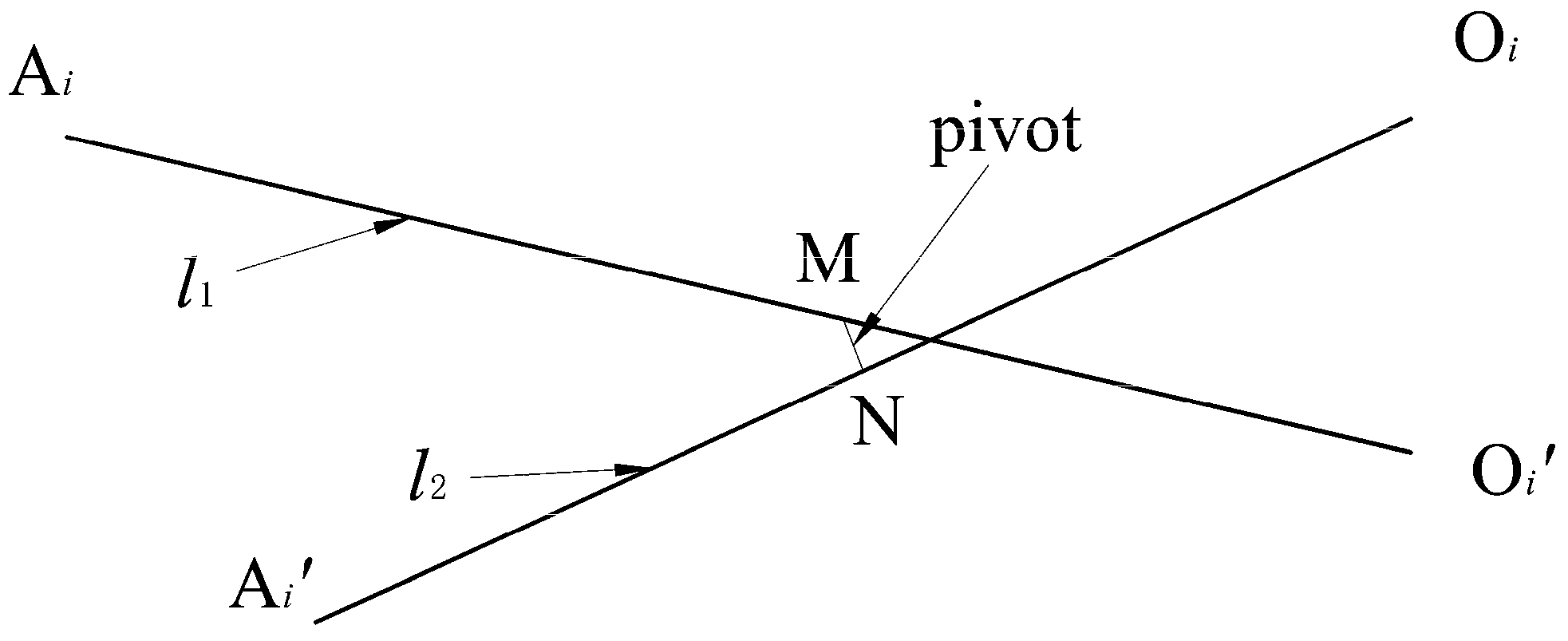
Assume that the two ends of the pivot axis are point M and point N (Figure 10), and the corresponding coordinates are (m1, m2, m3)T and (n1, n2, n3)T, respectively, where the superscript T is referred to as the transpose of a vector. The two endpoint coordinates of one axis l1 are (x11, y11, z11)T and (x12, y12, z12)T, and those of axis l2 are (x21, y21, z21)T and (x22, y22, z22)T. Therefore, the direction vector of each axis is (x12x11, y12y11, z12z11)T, (x22x21, y22y21, z22z21)T, and (n1m1, n2m2, n3m3)T. Due to the vertical relationships, these coordinates can be uniformly written as the following equation:
x j 2 x j 1 n 1 m 1 + y j 2 y j 1 n 2 m 2 + z j 2 z j 1 n 3 m 3 = 0 ,   j = 1 , 2
According to the above description, the straight lines along which the axis l1 and the axis l2 are located can be expressed as:
x x j 1 x j 2 x j 1 = y y j 1 y j 2 y j 1 = z z j 1 z j 2 z j 1 ,   j = 1 , 2
The points M and N are on these lines, as shown in the following:
γ 1 x j 1 x j 2 x j 1 = γ 2 y j 1 y j 2 y j 1 = γ 3 z j 1 z j 2 z j 1 = γ 0 ,   j = 1 , 2
When j = 1, γ represents the letter m, and the corresponding case represents the letter n. Further derivations can be conducted for the above equation:
γ 1 = γ 0 x j 2 x j 1 + x j 1 ,   γ 2 = γ 0 y j 2 y j 1 + y j 1 ,   γ 3 = γ 0 z j 2 y j 1 + z j 1 ,   j = 1 , 2
Combined with Equations (17) and (20), the following can be obtained:
x j 2 x j 1 n 0 x 22 x 21 m 0 x 12 x 11 + x 21 x 11 + y j 2 y j 1 n 0 y 22 y 21 m 0 y 12 y 11 + y 21 y 11 + z j 2 z j 1 n 0 z 22 z 11 m 0 z 12 z 11 + z 21 z 11 = 0 ,   j = 1 , 2
The above equation can be abbreviated as follows:
b j n 0 + c j m 0 = a j ,   j = 1 , 2
The solutions of these two linear equations are as follows:
m 0 = a 1 b 2 a 2 b 1 b 1 c 2 b 2 c 1 ,   n 0 = a 2 c 1 a 1 c 2 b 1 c 2 b 2 c 1
where the variables are listed below:
a j = x j 2 x j 1 x 21 x 11 + y j 2 y j 1 y 21 y 11 + z j 2 z j 1 z 21 z 11
b j = x j 2 x j 1 x 22 x 21 + y j 2 y j 1 y 22 y 21 + z j 2 z j 1 z 22 z 21
c j = x j 2 x j 1 x 12 x 11 + y j 2 y j 1 y 12 y 11 + z j 2 z j 1 z 12 z 11
The coordinates (m1, m2, m3)T and (n1, n2, n3)T can be obtained by providing the endpoint coordinates of axis l1 and axis l2. Since the outer contour of the SU has been determined in the previous section, the coordinates of one node per axis are known, that is, only the coordinates of the internal endpoints Oi and Oi’ of the inner SLE are unknown. However, from the construction of the structural configuration, the x-coordinate and y-coordinate values of the two nodes are both zero, and thus, the z-coordinate values become the only two geometric unknowns. By establishing a value for one z-coordinate and considering the foldability constraint, the other coordinate value will also become known. It should be noted that the preset value has a great influence on the structural self-locking ability. At this point, the foldability constraint of the inner SLE should be expressed as follows:
L A i M + L A i N = L
In this way, the problem of solving the member lengths of the inner SLEs and the pivot endpoint positions eventually reduces to the problem of solving the geometric parameter value (i.e., the z-coordinate value) inside an SU. To that end, a numerical solution can be obtained using a simple iterative method.

4. Geometric Design Methodology Considering Joint Sizes

The concepts and construction of the geometric design methodology for a half-span structure have been elaborated in the previous sections. However, the proposed methodology considering ideal joints can be used to preliminarily determine only whether the proposed set of design parameter values can obtain the required spatial configuration because the approach presented herein does not consider the joint dimensions. Thus, the results cannot be applied to an actual project. In this section, a disc-shaped hub joint commonly used in deployable grid structures is taken as an example to discuss the methodology considering joint sizes. Allowing for ideal joint conditions, the side elevation profile can be drawn using the geometric parameters of the overall structure. On this basis, the joint sizes will be considered in the following by regularly inserting the hub joints into the outer skeleton composed of ideal joints. In the proposed method, the hub center coincides with the ideal joint, and the ideal joint at this time becomes the intersection of a series of lines depicting the structural contour shape.
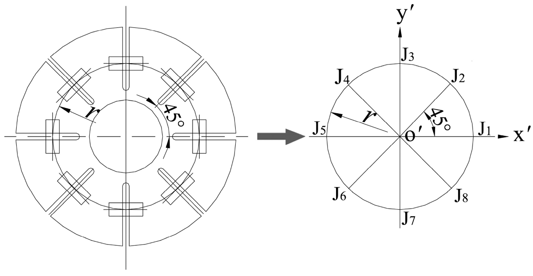
The hub joint is a discoid part with an equivalent radius r for connecting different rods, and the calculation model is shown in Figure 11. The spatial coordinate system still conforms to the right-hand rule, and the coordinate origin is at the centroid of the hub joint. The lines connecting the coordinate origin to the points Jk (k = 1, 2,…, 8) arranged counterclockwise along the circumference divide the disc into eight equal parts, where Jk represents the joint point between the rod end and the hub joint.

4.1. Spatial Configuration of Sus Considering Joint Dimensions

As mentioned earlier, for the preset geometric parameters that describe the side elevation profile of the structure, there are no differences between the structural model considering ideal joints and the one considering joint sizes. However, accounting for the sizes of joints will substantially change the member lengths, further resulting in changes in the unknown geometric parameters describing the grid structure profile and the unknown geometric parameter of the inner SLE of each SU.
Allowing for the symmetry of the SU and the convenience of assembly, the plane of each hub joint is supposed to be perpendicular to the hexahedral edge; for example, the joint at Ai is perpendicular to the intersection between the plane AiAi’Bi’Bi and the plane AiAi’Ai+1’Ai+1, the edge AiAi’. The SU model considering joint sizes is shown in Figure 12. The two inner hub joints are parallel to the xoy-plane, and the z-axis passes through their circle centers. A detailed description of the spatial transformation of the outer hub joints will be given in the following discussion. In addition, the selected geometric parameters describing the shape of the SU, including w, Li, and t, are identical to those describing the model considering ideal joints. Additionally, due to the symmetrical properties of the model, the three pairs of unknown SLEs are marked with different colored boldlines.
The construction of the SU model comprises the following steps:
  • The original relative positions between the joint coordinate systems and the unit coordinate system are illustrated in Figure 13a. The ideal joint positions are replaced by the circle centers. The three axes of the coordinate system of one hub joint are all parallel to the corresponding axes of the SU.
  • Rotate the joints at points Ai, Ai’, Bi’, and Bi about their y’-axes through an angle θi, and rotate the others in the peripheral SLEs through an angle -θi.
  • Rotate these joints again about their x’-axes. The joints at the points Ai, Ai’, Ai+1’, and Ai+1 are rotated through an angle -φ, and the others in the peripheral SLEs are rotated through an angle φ. Accordingly, based on the model construction process, the new unit configuration is obtained (Figure 13b) and φ = arctan ( d / t ) (Figure 9).

4.2. Outer SLEs Considering Joint Sizes

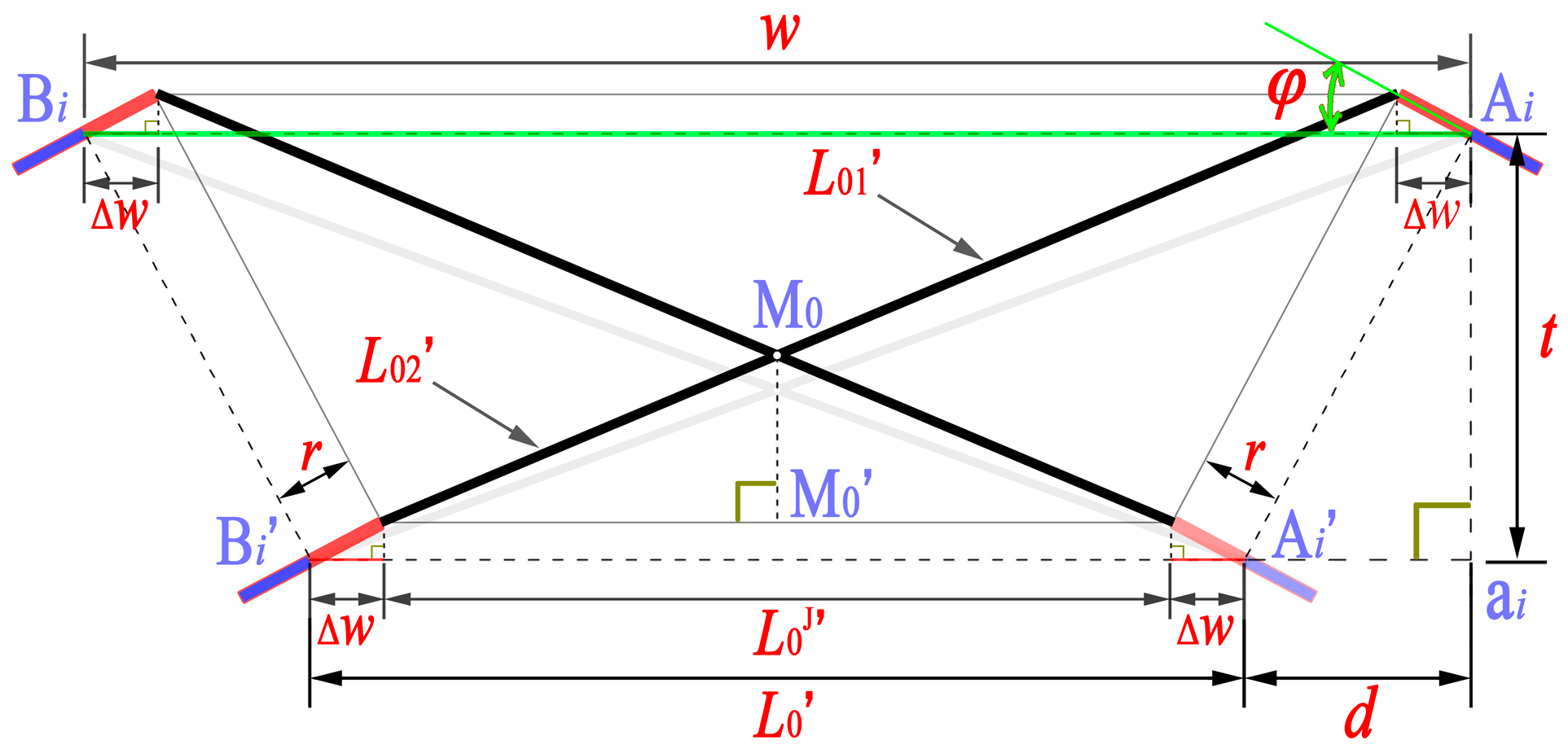
Based on the spatial transformation steps described above, joint point J7 on the hub joints Ai and Ai’ as well as joint point J3 on the hub joints Bi and Bi’ are still in the plane Ai’AiBiBi’. The new isosceles trapezoid consisting of these joint points is shown in Figure 14. M0’ is still the projection of M0 onto the short side. But, the length of the short edge becomes L0J. And M0 partitions the peripheral rod into two segments L01 and L02. Based on the side length without considering the joint sizes, a new side length can be obtained by reducing the length by 2Δw. The total length of each peripheral member can be derived as follows:
L = ( w 2 Δ w d ) 2 + t 2
The lengths of the two segments are expressed as follows:
L 02 = L 0 J / 2 w 4 Δ w 2 d × L
L 01 = L L 02
where Δ w = r cos φ , L 0 J = w 2 Δ w 2 d .
In the other plane AiAi’Ai+1’Ai+1, the total length of each rod is also L’ because of the foldability constraint and the symmetry of the structure (Figure 15). Similarly, after a series of transformations, point J5 on the hub joints Ai and Ai’ and point J1 on the hub joints Ai+1 and Ai+1’ are still on one plane. The side is reduced by 2∆Li. The longer side length is LiJ, and the shorter side length is LiJ. The pivot Mi partitions the peripheral rod into two lengths Li1 and Li2. Therefore, the following conclusions can be drawn:
L i 2 = L i J L i J + L i J × L
L i 1 = L L i 2
L i J = L i J 2 t sin θ i
L i J = ( L 2 d 2 ) ( t cos θ i ) 2 + t sin θ i
where Δ L i = r cos θ i .
In addition, the distance between the hub centers of the two hub joints Ai and Ai+1 can be expressed as follows:
L i = L i J + 2 Δ L i
For the overall structure considering joint sizes, when searching for the values of the unknown parameters Li and θi on the basis of the given geometric parameters t, r, d, W, S, and Hi, the geometric constraint Equation (12) needs to be replaced with Equation (35), and the simultaneous equations mentioned in Section 2.5 need to be solved.

4.3. Inner SLEs Considering Joint Sizes

For the inner SLEs, the spatial translation method presented above is not readily applicable for directly obtaining the rod length; therefore, the problem can be solved by calculating the position vector after the coordinate transformation of the rod endpoint. A brief introduction to the spatial transformation formula of the coordinate system is provided below:
P A = P BORG + R B A P B
where P A is the new nodal position vector in the global coordinate system A, and P B is the old vector for the same node in the local coordinate system B. P BORG denotes the origin position vector of B in A, and R B A denotes the rotation matrix:
R B A = r 11 r 12 r 13 r 21 r 22 r 23 r 31 r 32 r 33 = cos ( x A x B ) cos ( x A y B ) cos ( x A z B ) cos ( y A x B ) cos ( y A y B ) cos ( y A z B ) cos ( z A x B ) cos ( z A y B ) cos ( z A z B )
The elements of this matrix are the direction cosines between the axes of the two coordinate systems. For example, r12 is the direction cosine between the x-axis of A and the y-axis of B. In addition, R B A can be further written in an expanded form:
R B A = R C n A R C n 1 C n R C n 2 C n 1 R C m 1 C m R C 1 C 2 R B C 1
where Cm represents the intermediate stage of each small step change from B to A.
Therefore, the rotation matrix of each hub joint can be expressed according to the abovementioned transformation steps:
R o o = R o t ( y , ϕ 1 ) R o t ( x , ϕ 2 ) ,   ϕ 1 = ± θ i ,   ϕ 2 = ± φ
where R o t ( x , ϕ 1 ) is the rotation matrix rotating only about the x’-axis, and R o t ( y , ϕ 2 ) is the rotation matrix rotating only about the y’-axis.
Using the abovementioned spatial transformation theory, the spatial coordinates of the joint points Jk between the inner SLE members and the outer hub joints of the SU can be obtained.
In addition, for the convenience of the structural design, the coordinate vectors of the joint points on the two inner hub joints of the SU are listed below:
p J k o = r cos ( k 1 ) π 4 , r sin ( k 1 ) π 4 , z i s T ,   s = 1 , 2
where zi1 and zi2 are the z-coordinate values of the upper and lower inner hub joints, respectively, of the SU labeled i. When zis is zero, p J k o is the position vector of joint point Jk in the local coordinate system of the hub joint. Furthermore, Equations (20) and (23)–(27) can also be used to calculate the geometric parameters of the inner SLEs.

5. Design Examples and Physical Grid Structure

5.1. Design Examples of General Grid Structures

According to the design methodology proposed in this paper, the geometric design of an inner SLE is carried out separately after the design of the grid shape is completed, and the design should be based on the overall structural shape. In addition, for the geometric design of a general scissor structure that lacks a self-locking capability, it is fundamental to obtain the geometric parameters that determine the overall structural shape. Therefore, the design parameter values of the four sets of grid shapes that indicate the universal applicability of the proposed methodology to general double-layer deployable scissor structures are given first in Table 1.
The outlines of the four grid structures are plotted in Figure 16. Configuration a is a simple geometric form with an arbitrary curvature profile, whereas configuration b is a more common geometric form with a constant curvature profile. Configurations c and d represent geometric forms with generalized arbitrary curvature profiles, and the half spans of these two configurations can be assembled into a new structural configuration when the two configurations have the same side dimensions and conform to the foldability condition of the assembled structure. The diversity of structural forms can be immensely enriched by a similar assembly method.

5.2. Design Example of One Self-Locking Grid Structure

For a self-locking deployable grid structure, the geometric design of the inner SLE determines the self-locking ability of the structure and whether it can be smoothly deployed. Configuration a is selected as the design basis of the self-locking grid structure considering joint sizes for the convenience of both the calculation and the assembly, and all the geometric parameter values are listed in Table 2. For the inner SLEs of each SU, AiOi’ and Ai’Oi are selected to obtain the corresponding geometric parameter values. Moreover, to obtain a consistent table, the position vectors of the endpoints are listed separately in Table 3.

5.3. Physical Self-Locking Grid Structure

According to the results, a designed self-locking grid portion is subdivided into three components with array characteristics that are sequentially assembled into a complete physical grid structure. The members of this grid structure are made of hollow fiberglass tubes, the elastic modulus is 3.0 × 10⁴ MPa, and the density is 1.89 × 10⁻³ g/mm3; the cross section of the pipe has an outer diameter of 17.5 mm and a wall thickness of 1.6 mm. The physical self-locking grid structure can be smoothly deployed, as shown in Figure 17, thereby verifying the feasibility of the design methodology.
In addition, the hubs are made of polyhexamethylene adipamide, featuring an elastic modulus of elasticity of 3.8 × 10³ MPa and a density of 1.15 × 10⁻³ g/mm3. Certainly, the joints can be manufactured using any material that offers enough rigidity and suitable strength. Previous studies have shown that the choice of joint material has minimal effect on the self-locking capability of the structure presented in this paper [26,31]. In this study, the primary objective of selecting hub materials is to ensure that the structure has stable and reliable operational performance. Furthermore, with regard to further optimization of the hub structure design, the joint failure typically does not occur during the deployment process according to the relevant research we are carrying out. But there is a risk of destruction under ultimate load conditions after the structure is fully expanded. In conclusion, the hubs in the grid structure can meet the requirements for mechanism movement.
The output of a mature product requires a complete design process. For example, it has been found in practice that maintaining the self-locking performance index RF3b within a certain range for each SU ensures smoother unfolding and folding of the entire structure [31]. The example presented in this section only represents an interim result of a geometric design of the overall grid structure with suitable self-locking capability. Definitely, a series of subsequent research questions regarding geometric design, such as geometric parameter values selection, require a more in-depth and systematic exploration.

6. Conclusions

A geometric design model of deployable semicylindrical structures is proposed in this paper by introducing symmetrical structural characteristics. The proposed model considers the outer SLEs and the inner SLEs of the grid structure separately and establishes geometric constraint equations accordingly.
For the outer SLEs, instead of adding a geometric constraint on the side facade profile of the shell surface, the proposed methodology establishes a set of geometric constraint equations describing the shell surface profile by reasonably selecting some geometric parameters. Since the inner SLEs are considered separately, the number of coupled equations is relatively small. Therefore, the profile equations are concise and boast a high computational efficiency.
For the inner SLEs, the design methodology solves the parameter values of the inner SLEs based on the design of the external skeleton of the structure. The results of deriving the coordinate vectors of the general SLE pivot endpoints also provide an efficient approach for obtaining the complete geometric parameters of deployable self-locking grid structures.
When the sizes of the joints are taken into account, the member length can be corrected by the spatial translation method and the coordinate space variation method. By replacing the equation corresponding to an ideal joint with a modified equation for the side length of the SU and by forming a new system of equations, the structural shape with the joint sizes that satisfies the preset design parameters can be obtained.
The assembled physical structure can be successfully deployed, which verifies the feasibility of the methodology. Furthermore, some examples in this paper also show the universal applicability of the proposed methodology in the geometric design of a deployable scissor structure. This approach greatly enhances the innovative and expressive power of the design, thus painting a richer picture in terms of the diversity of structural design.

Author Contributions

Conceptualization, methodology, analysis, and writing—original draft preparation, Z.Z.; writing—review and editing, supervision, L.Y. All authors have read and agreed to the published version of the manuscript.

Funding

This research was funded by the Projects on Scientific Research Plan of the Shaanxi Province Education Department [grant number 23JK0309].

Data Availability Statement

Data are contained within the article.

Conflicts of Interest

The authors declare no conflicts of interest.

References

  1. Piñero, E.P. Three Dimensional Reticular Structure. U.S. Patent 3185164, 15 November 1961. [Google Scholar]
  2. Escrig, F.; Perez Valcarcel, J.; Sanchez, J. Deployable cover on a swimming pool in Seville. J. Int. Assoc. Shell Sp. 1996, 37, 39–70. [Google Scholar]
  3. Akgün, Y.; Gantes, C.J.; Sobek, W.; Korkmaz, K.; Kalochairetis, K. A novel adaptive spatial scissor-hinge structural mechanism for convertible roofs. Eng. Struct. 2011, 33, 1365–1376. [Google Scholar] [CrossRef]
  4. Buhl, T.; Jensen, F.V.; Pellegrino, S. Shape optimization of cover plates for retractable roof structures. Comput. Struct. 2004, 82, 1227–1236. [Google Scholar] [CrossRef]
  5. Wu-Jun, C.; Yao-Zhi, L.; Gong-Yi, F.; Jing-Hai, G.; Shi-Lin, D. A study on space masts based on octahedral truss family. Int. J. Space Struct. 2001, 16, 75–82. [Google Scholar] [CrossRef]
  6. Shi, Z.; Li, T.; Tang, Y.; Li, M.; Zhou, X.; Qian, J. Design and analysis of scissor-like hoop truss deployable antenna mechanism with arbitrary curvature support ribs. Acta Astronaut. 2024, 219, 24–40. [Google Scholar] [CrossRef]
  7. Roovers, K.; De Temmerman, N. Deployable scissor grids consisting of translational units. Int. J. Solids Struct. 2017, 121, 45–61. [Google Scholar] [CrossRef]
  8. Roovers, K.; De Temmerman, N. Geometric design of deployable scissor grids consisting of generalized polar units. J. Int. Assoc. Shell Sp. 2017, 58, 227–238. [Google Scholar] [CrossRef]
  9. Dinevari, N.F.; Shahbazi, Y.; Maden, F. Geometric and analytical design of angulated scissor structures. Mech. Mach. Theory 2021, 164, 104402. [Google Scholar] [CrossRef]
  10. García-Mora, C.J.; Sánchez-Sánchez, J. Geometric strategies to design a bistable deployable structure with straight scissors using stiff and flexible rods. Int. J. Solids Struct. 2022, 238, 111381. [Google Scholar] [CrossRef]
  11. Langbecker, T.; Albermani, F. Kinematic and non-linear analysis of foldable barrel vaults. Eng. Struct. 2001, 23, 158–171. [Google Scholar] [CrossRef]
  12. Mira, L.A.; Thrall, A.P.; De Temmerman, N. Deployable scissor arch for transitional shelters. Autom. Constr. 2014, 43, 123–131. [Google Scholar] [CrossRef]
  13. Kaveh, A.; Davaran, A. Analysis of pantograph foldable structures. Comput. Struct. 1996, 59, 131–140. [Google Scholar] [CrossRef]
  14. Pellegrino, S.; Calladine, C.R. Matrix analysis of statically and kinematically indeterminate frameworks. Int. J. Solids Struct. 1986, 22, 409–428. [Google Scholar] [CrossRef]
  15. Liao, Y.; Kiper, G.; Krishnan, S. Mobility analysis of tripod scissor structures using screw theory. Mech. Mach. Theory 2024, 191, 105468. [Google Scholar] [CrossRef]
  16. Arnouts, L.I.; De Temmerman, N.; Massart, T.J.; Berke, P. Geometric design of triangulated bistable scissor structures taking into account finite hub size. Int. J. Solids Struct. 2020, 206, 84–100. [Google Scholar] [CrossRef]
  17. Liao, Y.; Krishnan, S. Geometric design and kinematics of spatial deployable structures using tripod-scissor units. Structures 2022, 38, 323–339. [Google Scholar] [CrossRef]
  18. Zhang, R.; Guo, X.; Liu, Y.; Leng, J. Theoretical analysis and experiments of a space deployable truss structure. Compos. Struct. 2014, 112, 226–230. [Google Scholar] [CrossRef]
  19. Zhao, W.; Li, N.; Liu, L.; Leng, J.; Liu, Y. Mechanical behaviors and applications of shape memory polymer and its composites. Appl. Phys. Rev. 2023, 10, 011306. [Google Scholar] [CrossRef]
  20. Moy, J.J.; Tan, C.S.; Mohammad, S.; Abidin, A.R.Z. State-of-art review on deployable scissor structure in construction. Structures 2022, 42, 160–180. [Google Scholar] [CrossRef]
  21. Giménez Azorín, R.; Santana, M.V.B.; Berke, P.Z. Computational investigation of bistable and non-bistable deployable scissor structures. Structures 2024, 61, 106063. [Google Scholar] [CrossRef]
  22. Santana, M.V.B.; Arnouts, L.I.W.; Massart, T.J.; Gonçalves, P.B.; Berke, P.Z. Corotational 3D joint finite element tailored for the simulation of bistable deployable structures. Eng. Struct. 2021, 227, 111387. [Google Scholar] [CrossRef]
  23. Gantes, C.J. Deployable Structures: Design and Analysis; WIT Press: Southampton, UK, 2001. [Google Scholar]
  24. García-Mora, C.J.; Sánchez-Sánchez, J. The convergence surface method for the design of deployable scissor structures. Autom. Const. 2021, 122, 103488. [Google Scholar] [CrossRef]
  25. Zeigler, T.R. Collapsible Self-Supporting Structures. U.S. Patent 3968808, 13 July 1976. [Google Scholar]
  26. Zhao, Z.; Hu, W.; Yu, L. Experimental and numerical studies on the deployment process of self-locking cuboid foldable structural units. Adv. Struct. Eng. 2020, 23, 3496–3508. [Google Scholar] [CrossRef]
  27. Freire-Tellado, M.J.; Muñoz-Vidal, M.; Pérez-Valcárcel, J. Design of diagonalised square-base bistable modules. Arab. J. Sci. Eng. 2024, 49, 5949–5971. [Google Scholar] [CrossRef]
  28. Santana, M.V.B.; Hjiaj, M.; Berke, P.Z. Modal analysis of a bistable deployable module with a refined joint model. Eng. Struct. 2022, 269, 114798. [Google Scholar] [CrossRef]
  29. Pérez-Valcárcel, J.; Muñoz-Vidal, M.; Suárez-Riestra, F.; López-César, I.R.; Freire-Tellado, M.J. Deployable cylindrical vaults with reciprocal linkages for emergency buildings. Structures 2021, 33, 4461–4474. [Google Scholar] [CrossRef]
  30. Pérez-Valcárcel, J.; Muñoz-Vidal, M.; López-César, I.R.; Freire-Tellado, M.J.; Suárez-Riestra, F. Analysis of deployable cylindrical space bar structures of reciprocal linkages with frustoconical ends. Designs 2024, 8, 46. [Google Scholar] [CrossRef]
  31. Zhao, Z.; Yu, L.; Hu, W. Self-locking mechanism of foldable grid structures and capability evaluation of their structural units. Structures 2020, 27, 583–594. [Google Scholar] [CrossRef]
  32. Gantes, C.J.; Connor, J.J.; Logcher, R.D.; Rosenfeld, Y. Structural analysis and design of deployable structures. Comput. Struct. 1989, 32, 661–669. [Google Scholar] [CrossRef]
  33. Mira, L.A.; Coelho, R.F.; Thrall, A.P.; De Temmerman, N. Parametric evaluation of deployable scissor arches. Eng. Struct. 2015, 99, 479–491. [Google Scholar] [CrossRef]
  34. Escrig, F.; Valcarcel, J.P. Geometry of expandable space structures. Int. J. Space Struct. 1993, 8, 71–84. [Google Scholar] [CrossRef]
  35. Wujun, C.; Gongyi, F.; Jinghai, G.; Yanli, H.; Shilin, D. A new design conception for large span deployable flat grid structures. Int. J. Space Struct. 2002, 17, 293–299. [Google Scholar] [CrossRef]
  36. Kim, T.H.; Suh, J.E.; Han, J.H. Deployable truss structure with flat-form storability using scissor-like elements. Mech. Mach. Theory 2021, 159, 104252. [Google Scholar] [CrossRef]
  37. Gantes, C.J.; Konitopoulou, E. Geometric design of arbitrarily curved bi-stable deployable arches with discrete joint size. Int. J. Solids Struct. 2004, 41, 5517–5540. [Google Scholar] [CrossRef]
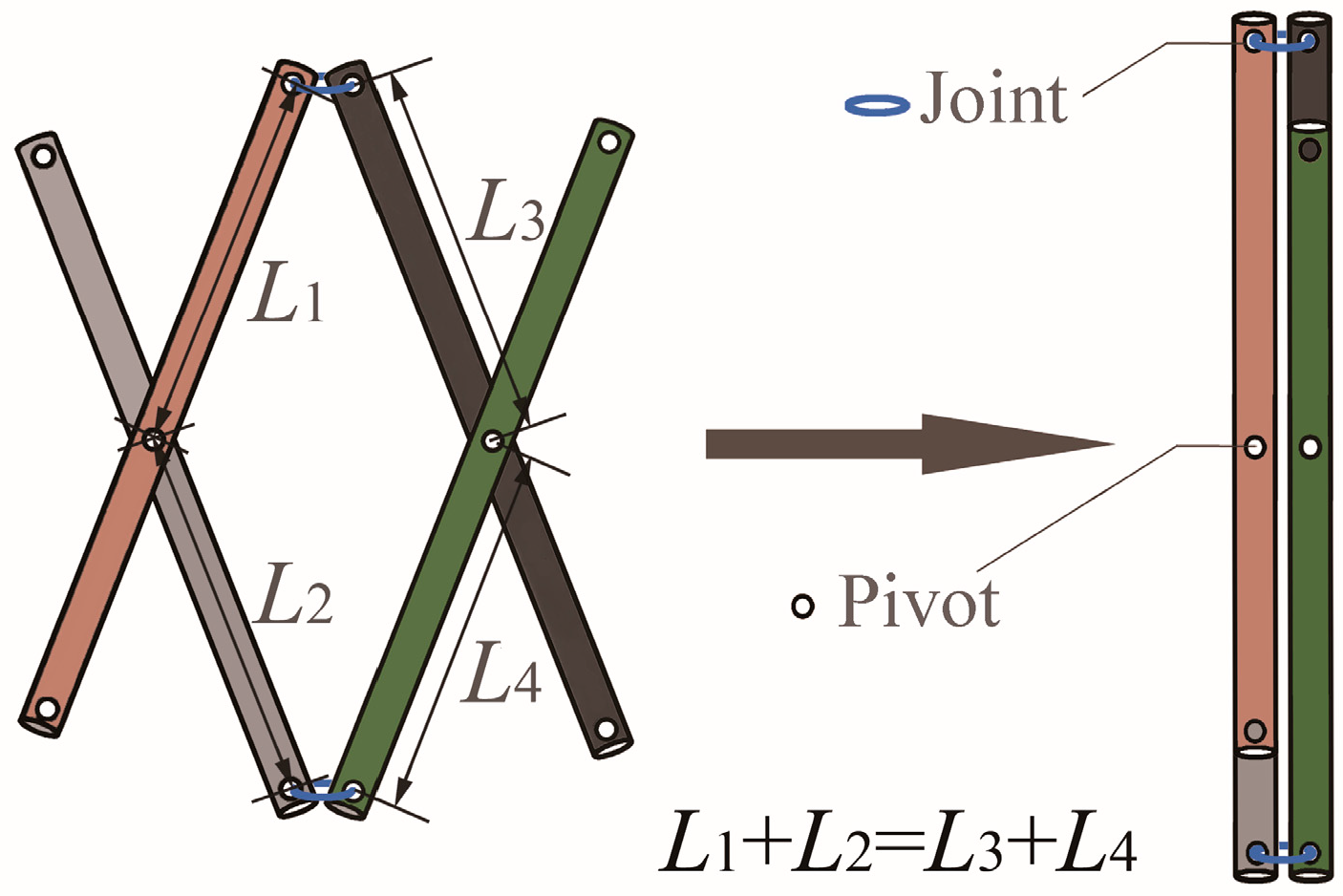
Figure 1. Scissors-like elements (SLEs) and foldability constraint.
Buildings 14 01690 g001
Figure 2. General deployable arch and self-locking deployable arch.
Buildings 14 01690 g002
Figure 3. Configuration of structural unit (SU).
Buildings 14 01690 g003
Figure 4. Construction of the double-layer semicylindrical grid model with ideal joints. (a) Projection of outer shell; (b) Projection of inner shell; (c) Two shell layers and outer layer surface; (d) Inner layer surface and SLEs in the lateral face; (e) Insert into other outer SLEs; (f) Insert into inner SLEs.
Buildings 14 01690 g004
Figure 5. Two types of configurations for the semicylindrical grid structure. (a) Configuration 1: an independent structural unit exists at the top of the grid; (b) Configuration 2: two structural units exist at the top of the grid.
Buildings 14 01690 g005aBuildings 14 01690 g005b
Figure 6. The first unit, at the bottom of the entire grid structure.
Buildings 14 01690 g006
Figure 7. General configuration of one unit with ideal joints.
Buildings 14 01690 g007
Figure 8. Outer SLE in the lateral face AiAi’Bi’Bi.
Buildings 14 01690 g008
Figure 9. Outer SLE in the lateral face AiAi’Ai+1’Ai+1.
Buildings 14 01690 g009
Figure 10. Inner SLE and its pivot MN.
Buildings 14 01690 g010
Figure 11. Real hub joint and corresponding geometric model.
Buildings 14 01690 g011
Figure 12. General SU model with joint sizes. The hub joint center coincides with the vertex of the hexahedron, and each hub is supposed to be perpendicular to the hexahedral edge.
Buildings 14 01690 g012
Figure 13. The construction of the SU model with considering hub joint sizes. (a) Original relative positions; (b) Final relative positions.
Buildings 14 01690 g013
Figure 14. Outer SLE in the lateral face AiAi’Bi’Bi with considering joint sizes.
Buildings 14 01690 g014
Figure 15. Outer SLE in the lateral face AiAi’Ai+1’Ai+1 with considering joint sizes.
Buildings 14 01690 g015
Figure 16. Four structural shapes of structure in side elevation.
Buildings 14 01690 g016
Figure 17. The fabricated structure and its deployment process.
Buildings 14 01690 g017
Table 1. The parameter values of deployable grid structure with four structural configurations.
ParameterUnitShape Type
abcd
n 3434
S/2mm2020.003010.001465.903000.00
W 1540.641271.071110.261110.26
t 300.00300.00300.00300.00
d 0.000.000.000.00
H1 1540.641305.991138.031145.00
H2 2790.322353.312218.492122.05
H3 2790.322934.533000.002732.45
H4 /2934.53/3000.00
φrad0.00000.00000.00000.0000
θ1 0.00000.22440.11710.1662
θ2 0.78540.22440.02590.2843
θ3 0.00000.22440.64240.1063
θ4 /0.2244/0.2287
L’mm1569.581305.991150.091150.09
L1 1540.641339.581145.881160.99
L2 1767.311339.581118.071197.59
L3 1540.641339.581304.461142.55
L4 /1339.58/1180.34
Table 2. The design results of a self-locking deployable grid structure with configuration a considering joint sizes.
Structural ConfigurationOuter SLEsInner SLEs
n 3L0Jmm1491.64LA1Mmm739.99
S/2mm2020.00L’ 1521.52LMO1′ 303.15
W 1540.64L01 760.76LA1′N 781.53
t 300.00L02 760.76LNO1 321.35
d 0.00L1J 1495.50LA2M 818.42
r 24.50L1J 1487.80LMO2′ 301.02
H1 1544.37L11 762.71LA2′N 703.09
H2 2790.32L12 758.79LNO2 317.84
H3 2790.32L2J 1710.21LA3M 743.34
θ1rad0.0128L2J 1301.00LMO3′ 303.16
θ2 0.7505L21 864.15LA3′N 778.17
θ3 0.0441L22 657.37LNO3 321.43
L’mm1521.51L3J 1504.93
L1 1544.49L3J 1478.47
L2 1746.05L31 767.50
L3 1553.88L32 754.01
Table 3. Position vectors of the inner SLE member endpoints.
Rotation Matrix and
Position Vector
First UnitSecond UnitThird Unit
R o o / 0.9999 0.0000 0.0128 0.0000 1.0000 0.0000 0.0128 0.0000 0.9999 0.7313 0.0000 0.6820 0.0000 1.0000 0.0000 0.6820 0.0000 0.7313 0.9990 0.0000 0.0441 0.0000 1.0000 0.0000 0.0441 0.0000 0.9990
p J 6 o A i mm(−17.32, −17.32, 0.00)T(−17.32, −17.32, 0.00)T(−17.32, −17.32, 0.00)T
P BORG A i (772.25, 770.32, 299.97)T(873.02, 770.32, 219.40)T(776.94, 770.32, 299.70)T
p o o A i (754.92, 753.00, 300.20)T(860.35, 753.00, 231.22)T(759.63, 753.00, 300.47)T
p J 6 o A i (−17.32, −17.32, 0.00)T(−17.32, −17.32, 0.00)T(−17.32, −17.32, 0.00)T
P BORG A i (768.40, 770.32, 0.00)T(668.42, 770.32, 0.00)T(763.71, 770.32, 0.00)T
p o o A i (751.07, 753.00, 0.22)T(655.75, 753.00, 11.82)T(746.40, 753.00, 0.76)T
p J 2 O i (17.32, 17.32, 370.00)T(17.32, 17.32, 317.60)T(17.32, 17.32, 370.00)T
p J 2 O i (17.32, 17.32, 246.71)T(17.32, 17.32, 196.22)T(17.32, 17.32, 246.32)T
M (231.68, 231.12, 262.25)T(244.01, 215.15, 205.63)T(232.36, 230.44, 262.01)T
N (231.12, 231.68, 262.27)T(216.08, 246.36, 222.40)T(230.44, 232.37, 262.07)T
Disclaimer/Publisher’s Note: The statements, opinions and data contained in all publications are solely those of the individual author(s) and contributor(s) and not of MDPI and/or the editor(s). MDPI and/or the editor(s) disclaim responsibility for any injury to people or property resulting from any ideas, methods, instructions or products referred to in the content.