Article

Finite Element Investigation of a Novel Cold-Formed Steel Shear Wall

by
Zhiqiang Xie
1,
Ye Bi
1,
Ying Fan
1,*,
Chengwei Gao
1,
Xiangdong Zhang
2,
Yin Feng
2,
Daxing Zhou
2 and
Lei Dong
2
1
School of Civil and Transportation Engineering, Beijing University of Civil Engineering and Architecture, Beijing 102616, China
2
China Railway Construction Group Co., Beijing 100070, China
*
Author to whom correspondence should be addressed.
Buildings 2024, 14(6), 1691; https://doi.org/10.3390/buildings14061691
Submission received: 17 April 2024 / Revised: 13 May 2024 / Accepted: 4 June 2024 / Published: 6 June 2024
(This article belongs to the Special Issue Research on the Seismic Design of Steel Frames)

Abstract

:
In this paper, a novel corrugated steel sheet central sheathed cold-formed steel (CCS-CFS) shear wall is proposed. This shear wall can address the problems of low shear strength and ductility in conventional cold-formed steel (CFS) shear walls caused by screw connection failure and eccentric sheet arrangement. A numerical simulation method for the novel shear wall was developed and verified through cyclic loading test results of two full-size shear wall specimens. Parameter analysis was then conducted to investigate the effects of screw spacing, sheet thickness ratio, and aspect ratio on the seismic performance of these shear walls, accompanied by design recommendations. The results indicated that this innovative shear wall configuration can effectively resolve the connection failure between the frame and the sheet. Furthermore, the CCS-CFS shear wall can effectively improve shear strength, energy dissipation capacity, and ductility. The developed numerical simulation method can accurately capture the hysteretic properties and failure modes of shear walls. In addition, it can address the shortcomings in conventional models that neglect the mixed hardening characteristic of steel and metal damage criteria, resulting in inaccurate simulation results and unrealistic buckling modes. The principal failure modes observed in the novel shear wall were identified as the plastic buckling of corrugated steel sheathing and the distortional buckling of the end stud. Reducing the screw spacing has a limited impact on its shear strength. It is recommended that the sheet thickness ratio of the CCS-CFS shear wall should be greater than 2.0, while the aspect ratio can be relaxed to 10:4.

1. Introduction

Earthquakes have a significant impact on the structural safety of buildings [1,2]. Many scholars have conducted research in this field. Deng, E et al. [3] presented an experimental–numerical investigation on an innovative fully prefabricated liftable connection (FPLC) for modular steel buildings (MSBs). The results indicate that the FPLC had a satisfactory deformation capacity and sufficient ductility under earthquake conditions. Yang, L et al. [4] proposed a displacement-amplified mild steel bar joint damper to solve some dampers that cannot give full play to the energy dissipation effect during small earthquakes. Wei, J et al. [5] carried out research on the seismic performance of concrete-filled steel tubular (CFST) composite columns with ultra-high performance concrete (UHPC) plates. These structures can withstand multiple earthquakes and have demonstrated good seismic performance.
A cold-formed steel (CFS) structure is a type of green building structure that has been widely used in low-rise residential [6,7] and office buildings due to its characteristics of light weight, high strength, industrialization and a high degree of assembly. In recent years, propelled by advancements in the construction industry, the CFS structure system has become a promising prospect for development in mid and high-rise constructions.
The main lateral stability and strength in CFS structures are provided by CFS shear walls. Therefore, the seismic performance of a shear wall [8,9,10] critically influences the seismic performance of the whole structure. Research by Niari et al. [11] and Feng et al. [12] revealed that the screw connection between the sheet and the frame in a single-sided CFS shear wall was prone to tilt and slip in the process of stress. This resulted in a noticeable pinching effect of the hysteretic curves and poor energy dissipation of components. In addition, screw connection failure was a brittle form of failure which meant that the seismic potential of components was not fully exploited, resulting in low shear strength and ductility of the shear wall. To address the above problems, a self-piercing rivet (SPR) connection and a hybrid connection (SPR and screws) were developed by Xie et al. [13,14]. Through experimental investigations, the researchers proposed methods for calculating the shear and tensile strength for these two types of joints, significantly improving the connection performance of shear walls. Therefore, improving the screw connection performance or introducing new connection types is an effective way to enhance the seismic performance of CFS shear walls.
An important reason for the low shear strength and ductility of CFS shear walls is the eccentric force caused by the single-sided placement of sheathing. Research conducted by Rizk and DaBreo et al. [15,16] revealed that the off-center positioning of the sheet subjected the studs of the wall to torsional moments. Furthermore, shear buckling deformations of the sheathing led to the sheet pulling over the heads of the screws, resulting in a loss of the out-of-plane constraint of the sheet on the steel frame. This decreased the compression strength and anti-collapse capabilities of the shear wall. Given these findings, experimental investigations on double-sheathed shear walls were completed by Santos [17]. The results indicated that while this new configuration effectively improved the torsional strength and stiffness of the wall, the challenge of low ductility due to premature screw connection failures remained. Subsequently, Wang et al., Briere et al. and Rogers et al. [18,19,20] innovatively proposed the center-sheathed CFS shear wall. Although this innovation partially solved the aforementioned problems, shear bearing capacity and stiffness were not substantially enhanced, owing to the low lateral stiffness of steel plates and the susceptibility to out-of-plane buckling.
For this reason, Yu et al. and Zhang et al. [21,22] developed a CFS shear wall sheathed with corrugated steel sheets. They found that corrugated steel sheathing demonstrated superior shear resistance compared to conventional steel sheathing. However, the main failure modes were screw connection failure and end stud buckling, with limited improvement in ductility.
Developing a numerical model of a CFS shear wall is an important way to simulate and predict its failure mode and hysteretic properties. Ngo et al. [11] proposed a numerical simulation method for CFS shear walls. However, the rigidity assumption of the sheathing was adopted in the modeling process, which meant the relative displacement of the sheet was ignored. As a result, the peak load and initial stiffness of the simulation results were too small, and the decreasing section of the hysteretic curve was not obvious. Niari [23] and Xu et al. [24] conducted finite element analysis of CFS shear walls by considering geometric and material nonlinearity, but this did not effectively solve the aforementioned problems. Additionally, Xu assumed the steel sheet to be an ideal elastic–plastic material, but this led to plastic deformation occurring easily in the middle of the steel sheet or the screw connection area at the corner of the wall. This significantly reduced the computational efficiency of the model.
To sum up, while the existing numerical model of a CFS shear wall considered material and geometric non-linearity to enhance its accuracy, the utilization of an ideal elastic–plastic constitutive model for steel proved inadequate. This manifested in challenges such as overly high initial stiffness and the absence of a clearly delineated decline section within the simulated hysteretic curve. Therefore, the numerical simulation of a CFS shear wall that considers the characteristics of steel mixed strengthening and metal damage criteria requires further development.
According to the aforementioned scholars’ research on traditional CFS shear walls, it is evident that the conventional cold-formed steel (CFS) shear wall exhibited weak resistance and low ductility caused by screw connection failure and eccentric sheet arrangement. To achieve a stronger and more ductile CFS shear wall, an innovative corrugated steel sheet central sheathed cold-formed steel (CCS-CFS) shear wall was conceived. Based on this, a refined numerical simulation method of the CCS-CFS shear wall was developed by considering the characteristics of steel mixed strengthening and metal damage criteria. The three issues of undersized peak load, excessive initial stiffness, and the decreasing section of the hysteretic curve were not obvious and could be effectively resolved. The effectiveness of the method was verified by cyclic loading test results of two full-size shear wall specimens. Following the validated finite element model, a comprehensive finite element analysis was conducted on parameters such as screw spacing, sheet thickness ratio, and aspect ratio. The impact of these parameters on the seismic performance and failure mechanism of the shear wall was systematically studied.

2. Design and Experimental Program of CCS-CFS Shear Wall Configuration

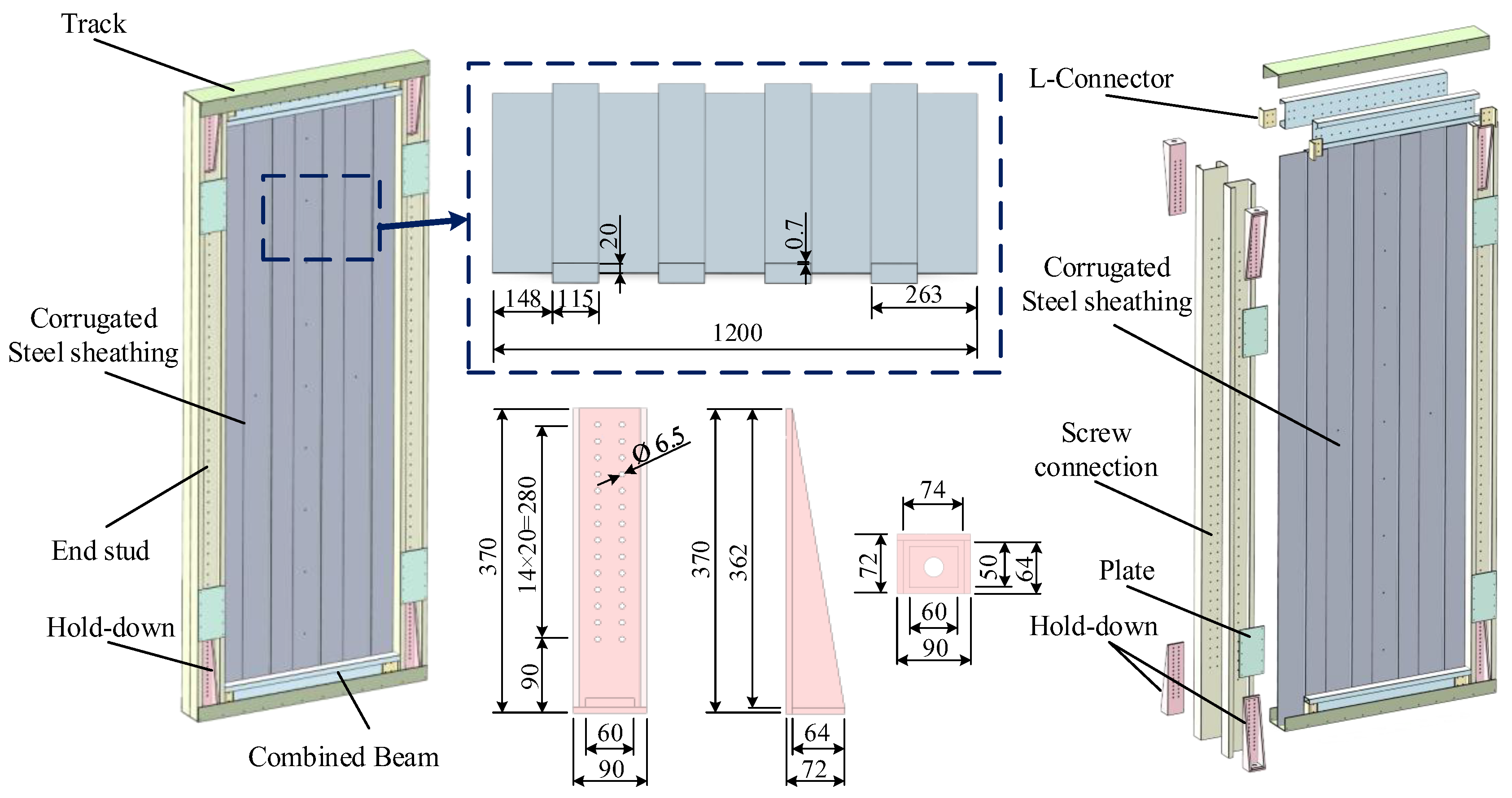
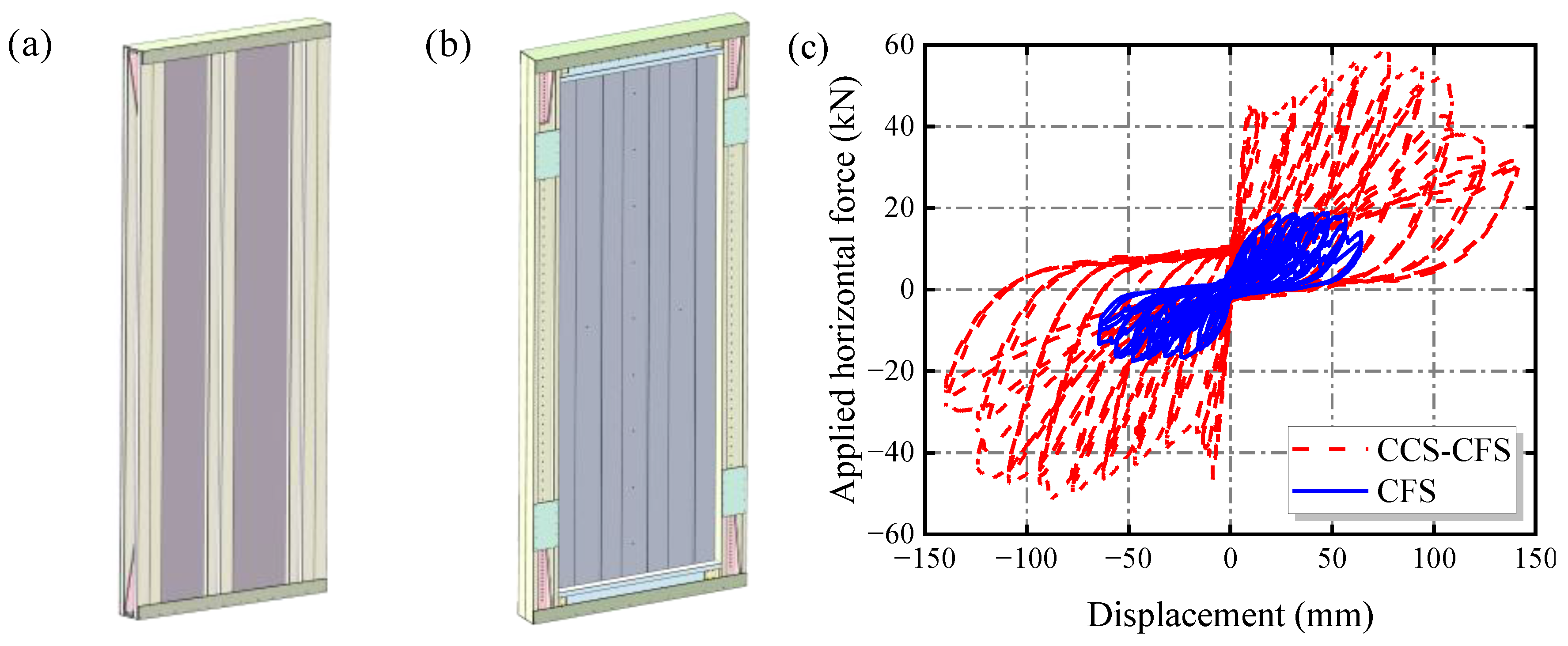
2.1. Innovative Configuration of the CCS-CFS Shear Wall

As a response to the limited strength and ductility of conventional CFS shear walls, this paper presents an innovative CCS-CFS shear wall with corrugated steel sheet central sheathing, as depicted in Figure 1. In this configuration, two back-to back corrugated steel sheets were centrally confined within the framing, providing a substantial increase in both shear resistance and ductility in comparison with conventional shear walls. The corrugated steel sheets were sandwiched by built-up vertical studs along the edges and horizontal members located at the base and top of the wall. Additionally, L-shaped connectors were used to connect the studs and the horizontal members, enhancing the overall stability of the shear wall through improved component connections. Furthermore, a symmetrical arrangement of hold-downs on both sides of the wall was employed to enhance connection performance and prevent hold-down failure or damage.
Compared with the conventional shear wall, the CCS-CFS shear wall offers the following advantages: (1) The two back-to-back corrugated steel sheets are centrally confined within the framing and sandwiched by built-up vertical studs along the edges and horizontal members located at the base and top of the wall. While ensuring a tight fit between the sheet and frame, the shear surface of the screws can be increased to avoid premature failure or pulling out of the sheets. This enhancement can significantly improve the shear strength and stiffness of the wall. (2) Placing the sheet in the middle of the frame serves a dual purpose. Firstly, by eliminating the torsion effect of the column caused by the eccentricity of the panel, it enhances the wall’s compression and collapse resistance. Secondly, it generates extra connection space and augments the number of connections between the sheet and frame. This reinforcement amplifies the skin effect of the sheet, enlarges the slip space of the connection, and ultimately enhances the ductility and seismic energy dissipation capabilities of the wall. (3) As a high-performance lateral force resistance component, the novel shear wall can be applied not only in multi-story steel structures but also in low-story CFS structures.

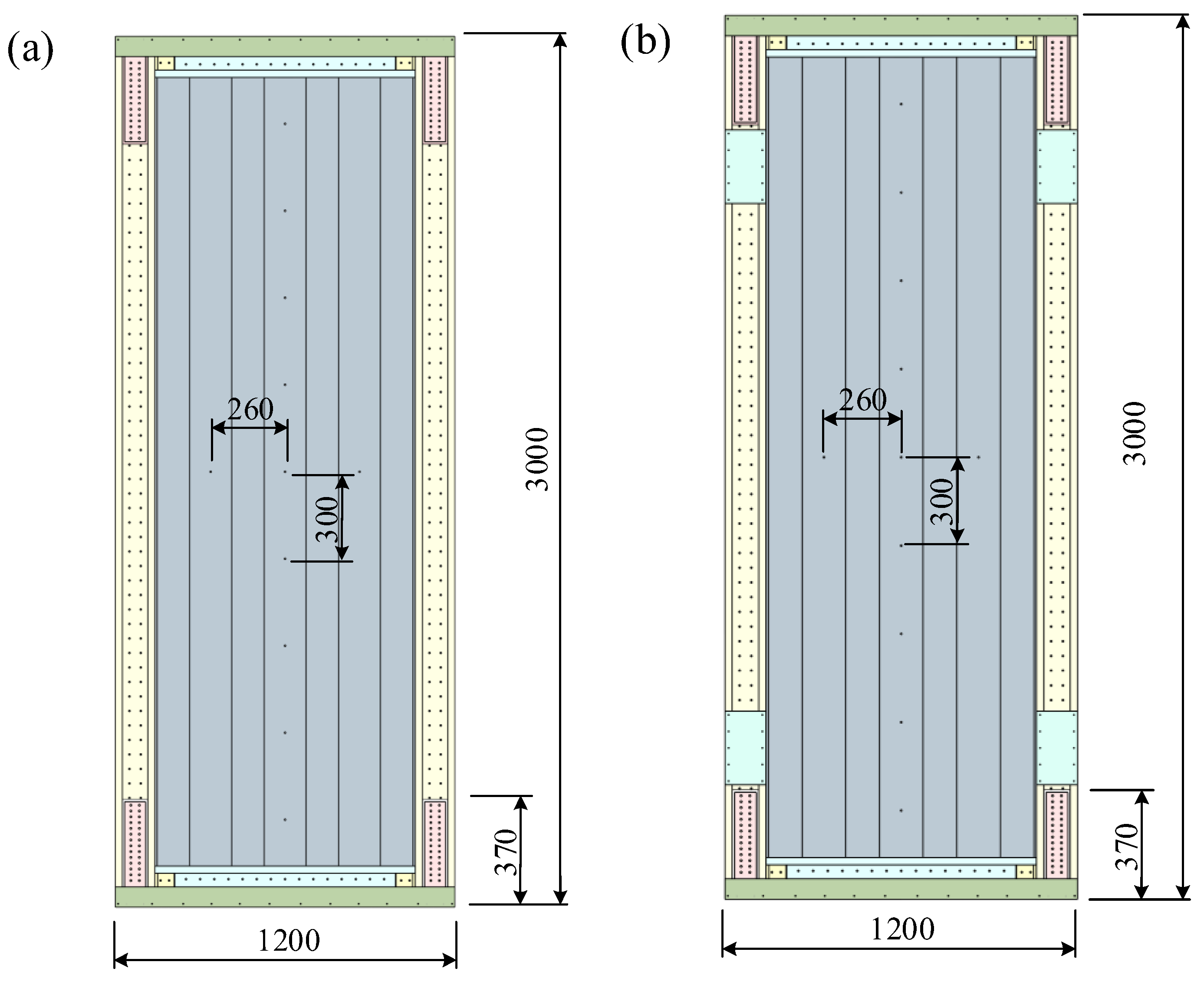
2.2. Specimen Design

Two full-size CCS-CFS shear wall specimens were designed and manufactured. The height and width of all specimens were 3000 mm and 1200 mm, respectively. The transverse brace comprised double C-shaped steel with 140 mm web × 55 mm flange × 25 mm lip × 2 mm thickness, fastened together by two lines of screws at intervals of 50 mm along the length of the web. The end studs consisted of two coupled C-shaped steel with 140 mm web × 75 mm flange × 25 mm lip × 2 mm thickness, fastened together by two lines of screws at intervals of 50 mm along the length of the web. The track comprised double U-shaped steel with 160 mm web × 70 mm flange × 2 mm thickness attached by two lines of SPRs at intervals of 50 mm along the length of the web. The interval between the two lines of screws was 40 mm. The cross-section size of the corrugated steel sheet was CS 1200 mm × 148 mm × 115 mm × 20 mm, with a thickness of 0.7 mm. The end studs of specimen SW-1 were not equipped with plates, while the end studs of specimen SW-2 were equipped with plates. Figure 2 presents the detailed configurations of the specimens.
ST5.5-grade screws were used for the shear wall. Due to the different thickness of the connected sheet, the length of the screw between the combined transverse brace and the corrugated steel sheet was 25 mm; the length between the transverse brace and the wave trough was 70 mm; and the length between the end studs and the corrugated steel sheet was 32 mm. ST6.3-grade screws were employed between the hold-downs and the steel frame. The failure modes, hysteretic curves, skeleton curves, and test results of two specimens were obtained by conducting cycle loading tests.

2.3. Material Properties

In accordance with Chinese Standard GB/T 228.1 [25], three coupons were tested for each component the results of which are presented in Table 1. The strength-to-yield ratio (fu/fy) of coupons was greater than 1.2 and the elongation did not fall below 10%. The ductility of materials satisfied the provision of North American specification AISI S100-16 [26].

2.4. Test Results Analysis

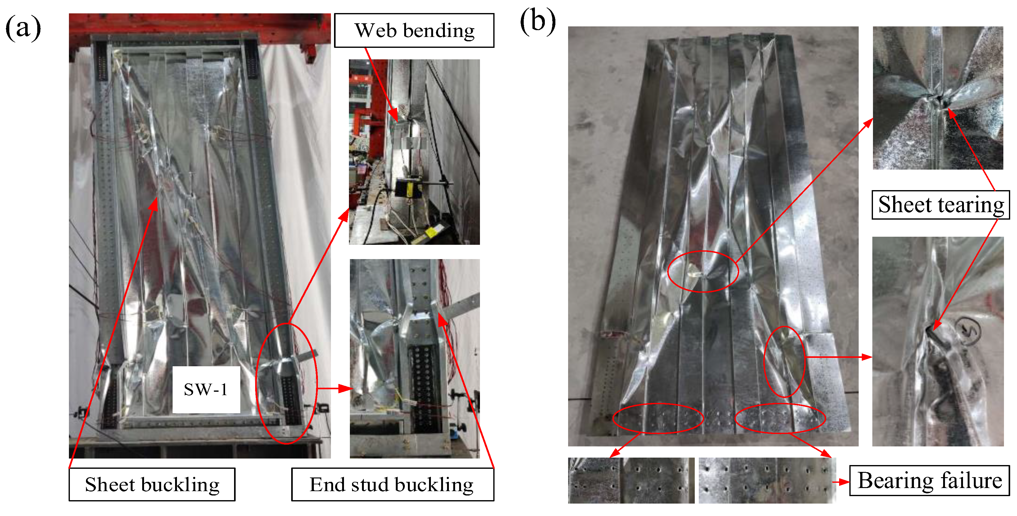
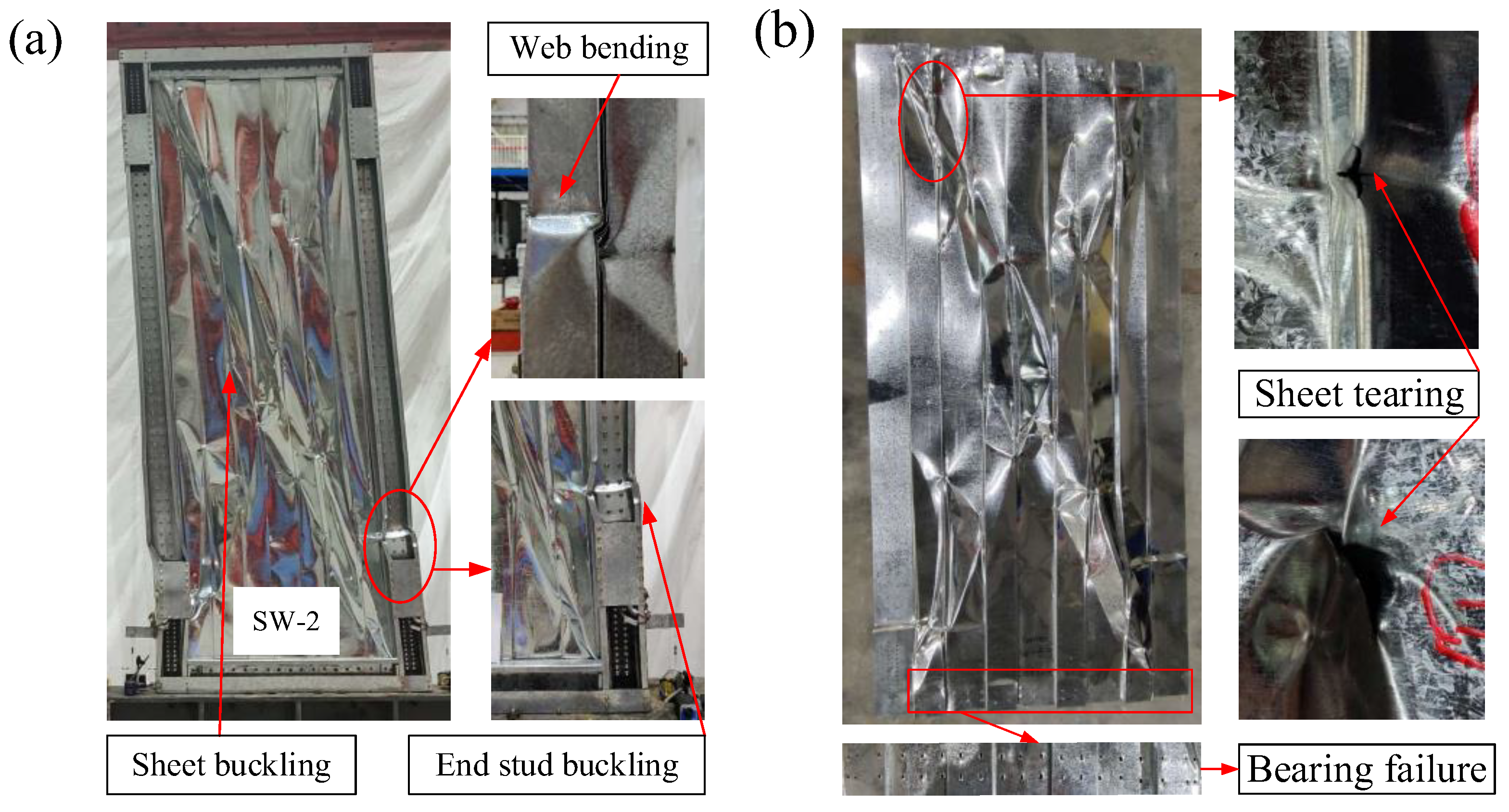
2.4.1. Failure Modes

At low load levels, both specimens exhibited elastic shear buckling of the corrugated steel sheet. When horizontal displacement reached 8mm, plastic buckling of the corrugated steel sheet was observed. At this point, the shear strength of the two specimens decreased, and the decline of specimen SW-1 was larger. As the horizontal displacement continued to increase, the shear strength of the two specimens gradually increased and a tension field appeared along the diagonal of specimens, as depicted in Figure 3a and Figure 4a. Simultaneously, the two flanges at the bottom of the left end stud buckled and the specimens entered the failure stage. When the wall shear strength dropped to 85% of the peak load, the test was terminated and the specimens were considered destroyed, as illustrated in Figure 3 and Figure 4. To summarize, the main failure modes of the novel shear wall were the plastic buckling of corrugated steel sheathing and the distortional buckling of the end stud. Most notably, the distortional buckling of the end stud was the key factor affecting the shear strength of the shear wall.

2.4.2. Hysteresis Curves

Figure 5 presents the hysteresis curves for each specimen. The test results are presented in Table 2. As depicted in Figure 5, the hysteresis curves of specimens SW-1 and SW-2 were similar. When the peak load was achieved, the shear strength of the specimens significantly degraded. The plastic hinge formed by the buckling of the end stud and the plastic deformation and tearing of the steel sheet increased the slip of the hysteresis curve, making the “pinched” phenomenon more obvious. Compared with specimen SW-1, the deformation capacity and cumulative energy dissipation capacity of specimen SW-2 increased by 16.4% and 16.6%, respectively. This was because the addition of plates to the end studs significantly enhanced its local flexural and compressive strength, effectively delaying the buckling and failure process. However, the shear strength and stiffness of the wall primarily depended on the sheet and steel frame, while the plate served merely to locally strengthen the end stud without directly enhancing the shear strength of the sheet or steel frame. Thus, the impact of adding plates on the shear strength and stiffness of the shear wall was relatively small.

2.4.3. Comparison with the Conventional CFS Shear Wall

Based on the test results obtained by Xie et al. [27], this section presents a comparison of the hysteretic curves and seismic performance indexes between the conventional CFS shear wall (Figure 6a) and specimen SW-2 (Figure 6b). The results of the comparison of hysteresis curves are displayed in Figure 6c. As depicted in Figure 6, specimen SW-2 demonstrated an approximately 60% increase in steel usage compared with the conventional CFS shear wall. Nevertheless, notable enhancements were observed in its shear stiffness, shear strength, and cumulative energy consumption, with increases of 267%, 208%, and 175%, respectively. In summary, the seismic performance of the CCS-CFS shear wall markedly improved compared with the conventional CFS shear wall. Hence, it is advisable to consider employing the CCS-CFS shear wall as a prospective lateral force resistance solution within a multi-layer CFS structure system.

3. Numerical Methodology

3.1. Modeling of Shear Walls

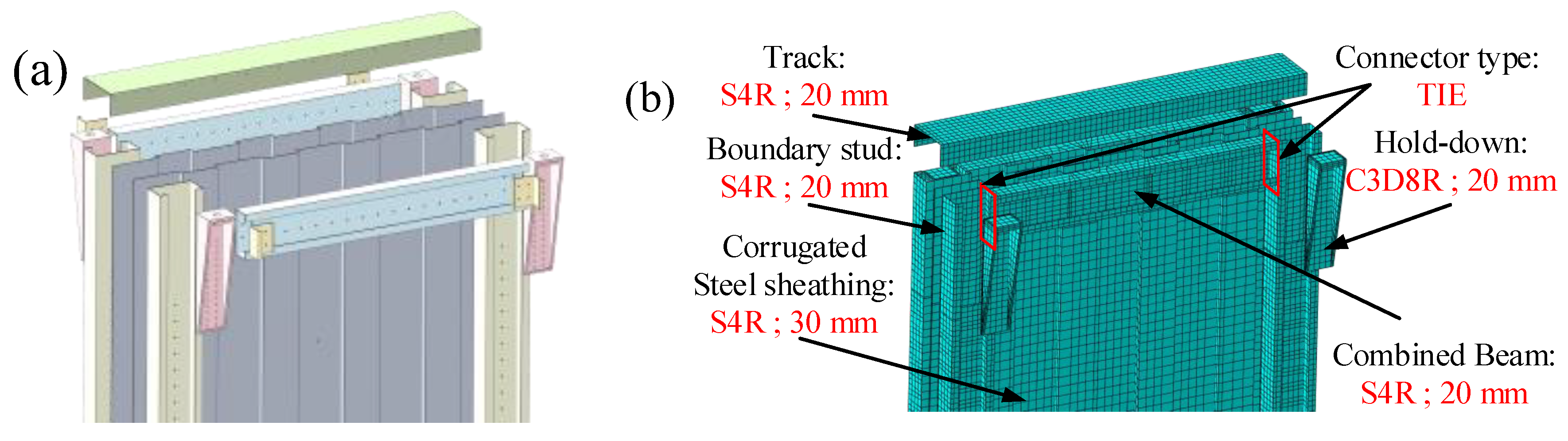
3.1.1. Element Choice and Mesh Size

As depicted in Figure 7, the S4R shell element was adopted to model the steel frame and sheet sheathing in ABAQUS [28]. The dimensions of the model were consistent with the specimen. During finite element modeling, an odd number of section points is specified throughout the shell thickness when integrating properties during analysis. Due to the relatively uniform thickness of materials within the wall, ABAQUS employs five section points throughout the thickness of a homogeneous shell. A study by Schafer et al. [29] revealed that the local, distortional and global buckling failure modes can be simulated more accurately with medium or suitable mesh. Therefore, the mesh size for the steel frame was set at 20 mm, while the mesh size for the sheet sheathing was 30 mm (Figure 7b).

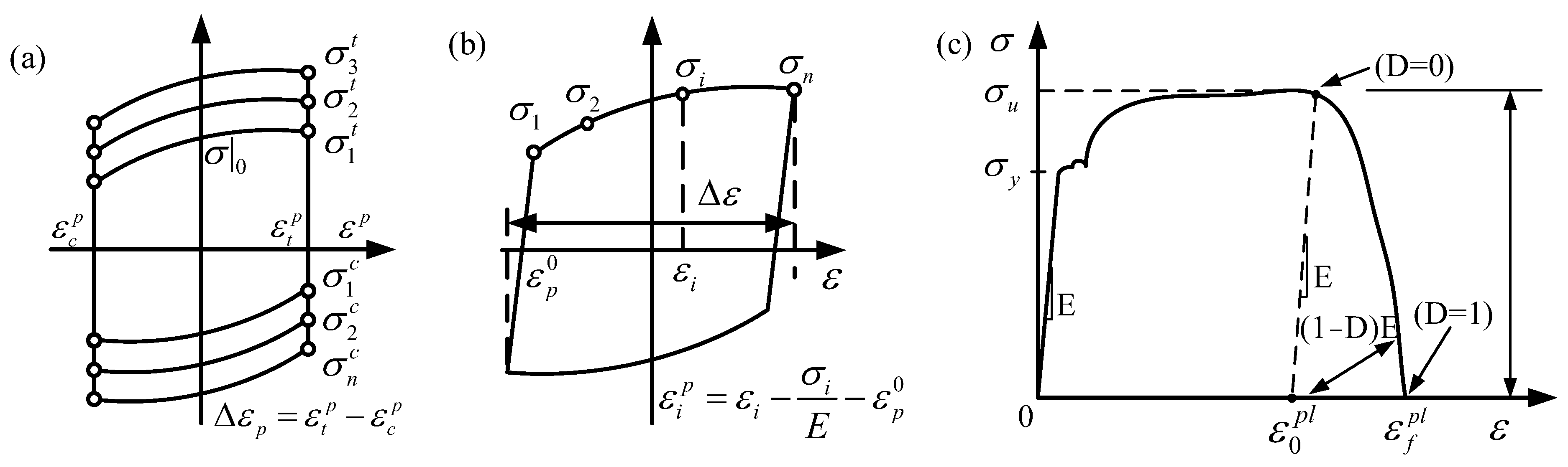
3.1.2. Material Modeling

According to the von Mises yield criteria [30], the steel exhibited the characteristics of mixed strengthening, as displayed in Figure 8a. To accurately simulate the hysteresis curve of the actual steel material, the combined module in ABAQUS and cycle hardening material properties were employed to simulate the steel under cycle loads. Material parameters were fitted using reference [31], and the results are detailed in Table 3.
Furthermore, steel material properties were determined according to coupon tests. The nominal stress ( σ n o m ) and strain ( ε n o m ) data were obtained from the material test (Table 1), and transformed into the input true stress ( σ t u r e ) and strain ( ε t u r e ) based on Equations (1)–(3) [32], as displayed in Figure 8b. Figure 8c depicts the true stress–strain curve of steel under tension. In order to achieve a more precise simulation of the failure behavior of the shear wall, ductile damage properties were incorporated into the material constitutive model. Additionally, the damage evolution sub-term of the steel damage evolution path was included.
ε n o m = l l 0 l 0 = l l 0 1
σ t u r e = σ n o m 1 + ε n o m
ε t u r e = ln 1 + ε n o m

3.1.3. Geometric Nonlinearity

Geometric nonlinearity in structural analysis pertains to the requirement of generating a new equilibrium equation based on the deformed state of a structure following significant deformation. Failure to account for this phenomenon can lead to substantial calculation errors due to the evolving shape and behavior of the structure under load. For example, consider a cantilever beam loaded vertically at the tip. If the tip deflection is small, the analysis can be considered as being approximately linear. However, if the tip deflections are large, the shape of the structure, and hence its stiffness, changes. Therefore, the geometric nonlinearity of the cantilever beam needs to be considered [33].
Consequently, because each member of the CCS-CFS shear wall was a shell element, the presence of geometric nonlinearities became particularly pronounced. When subjected to bending loads, these shell elements were prone to significant deformations, resulting in substantial displacements and rotations at critical buckling points within the structure. Therefore, the influence of geometric nonlinearity on shear wall must be considered in finite element analysis.

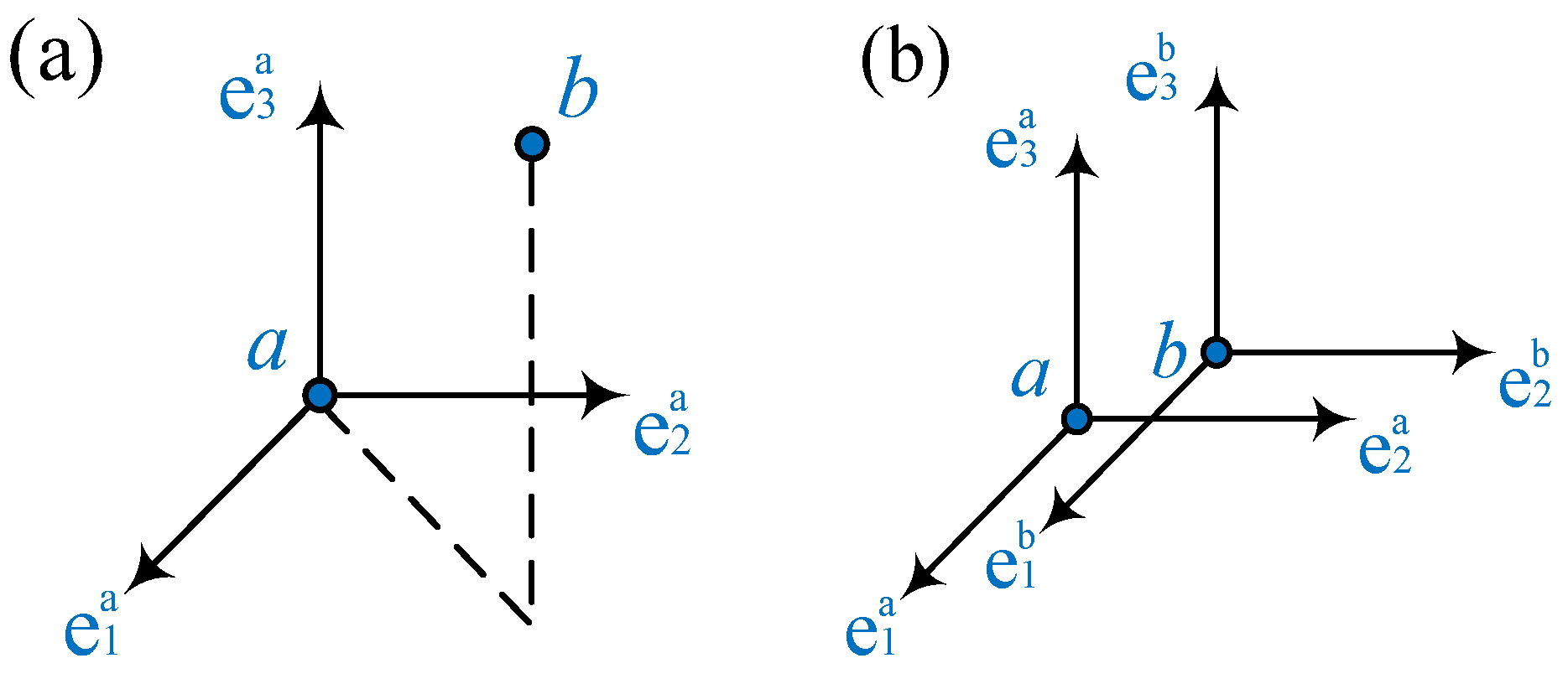
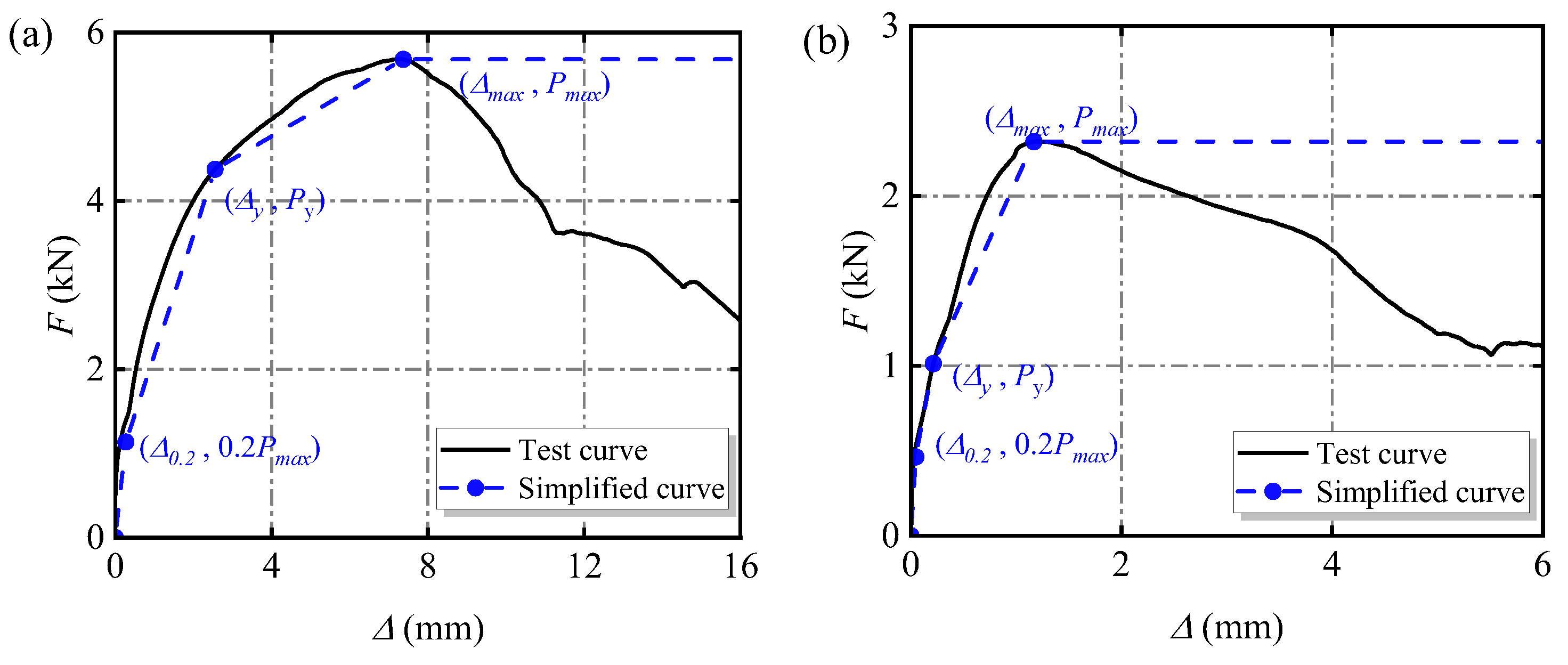
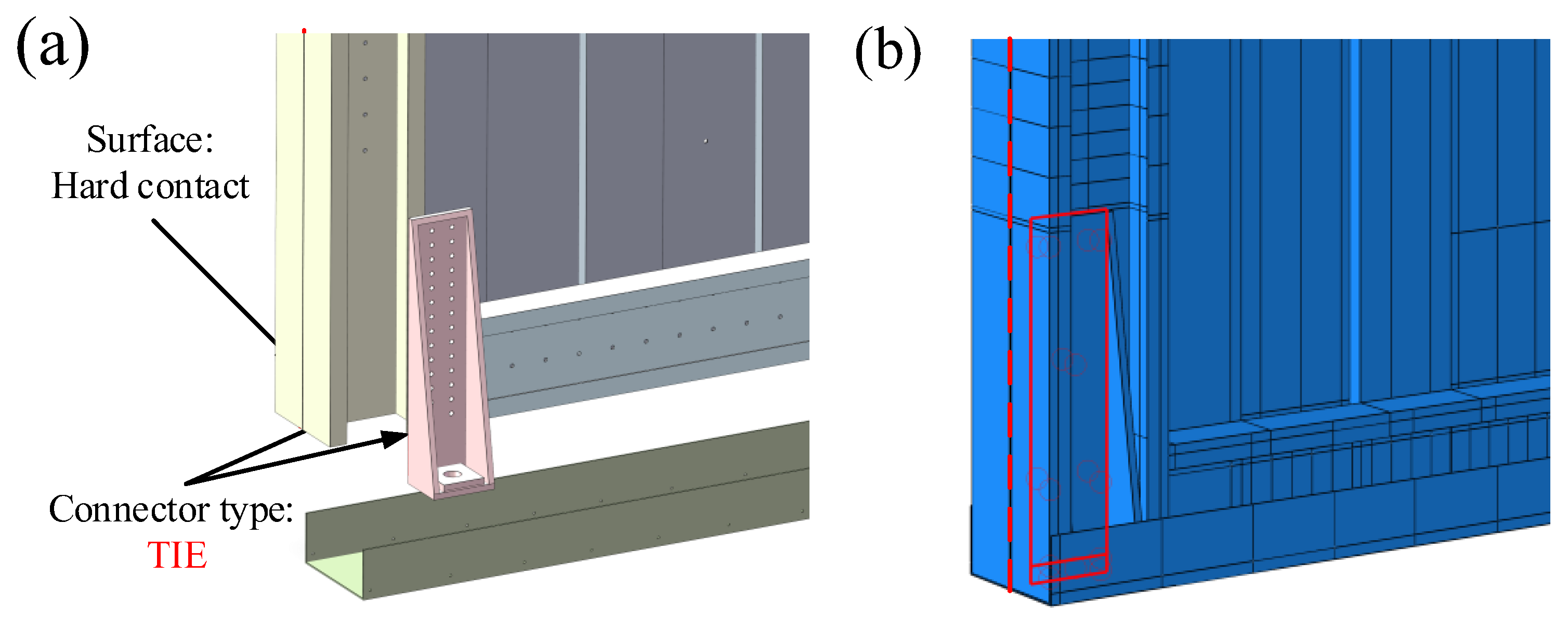
3.1.4. Modeling of the Screw Connection

The screw connection in the shear wall can be classified into three categories based on the varying base steel thicknesses: (1) connection between the track and the transverse brace (2 + 2 mm); (2) connection between the corrugated steel sheet and the end stud (2 + 0.7 + 0.7 + 2 mm); (3) connection between the corrugated steel sheet and the transverse brace (2 + 0.7 mm). Based on the test results, it was found that the screw connection between the track and the transverse brace remained essentially intact, with no instances of connection failure. Consequently, it was inferred that the joint exhibited rigidity, and was consequently modeled using a TIE constraint in the simulation. Slight hole wall expansion was evident in the connection between the corrugated steel sheet and the steel frame, indicating that a relative slip occurred between the two components. Thus, it was assumed that the joint was hinged and was simulated by a Cartesian connector (Figure 9). Because the combined plate thickness of the corrugated steel sheet and end stud differed from that of the corrugated steel sheet at the wave crest and transverse brace, two different constitutive models of screws were required for simulation. The constitutive model and calculation parameters are presented in Figure 10 and Table 4.
Figure 11 presents a simplified diagram of the hold-downs in the finite element model. During the cyclic loading tests, no damage was observed on the hold-downs, and they consistently remained within the elastic range. Therefore, the solid unit C3D8R was employed to simulate the hold-downs, and the constraint between it and the end stud was simplified to the TIE constraint.

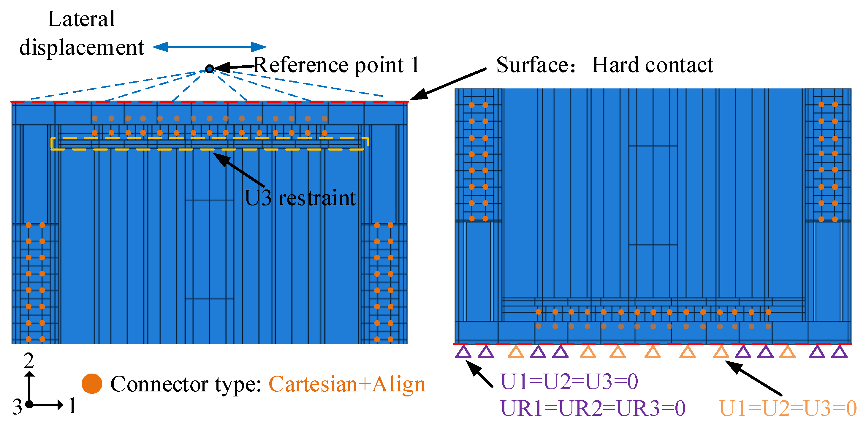
3.1.5. Boundary Conditions and Loading Mode

According to the test, the simulation of the boundary conditions of the CCS-CFS shear wall was primarily divided into the following: (1) The relationship between the top track and the loading beam. The web plate of the upper track was coupled to the reference point RP-1, and the translation degree of freedom in the loading direction was constrained. (2) Preventing out-of-plane instability of the wall during loading. The translation degree of freedom in the external direction of the wall was restricted. (3) The connection between the bottom track and the beam. The translation degree of freedom between the bottom track and the hold-downs was restricted. (4) Surface-to-surface contact with ‘‘hard-contact’’ behavior in a normal direction was introduced to simulate the interfaces between the frame members and the sheet. Additionally, the tangent behavior of interfaces was defined as frictionless, as depicted in Figure 12. To improve convergence in the analysis and acquire a hysteresis curve featuring a descending branch, we employed a monotonic loading scenario utilizing displacement-control loading within the model.

3.2. Model Validation

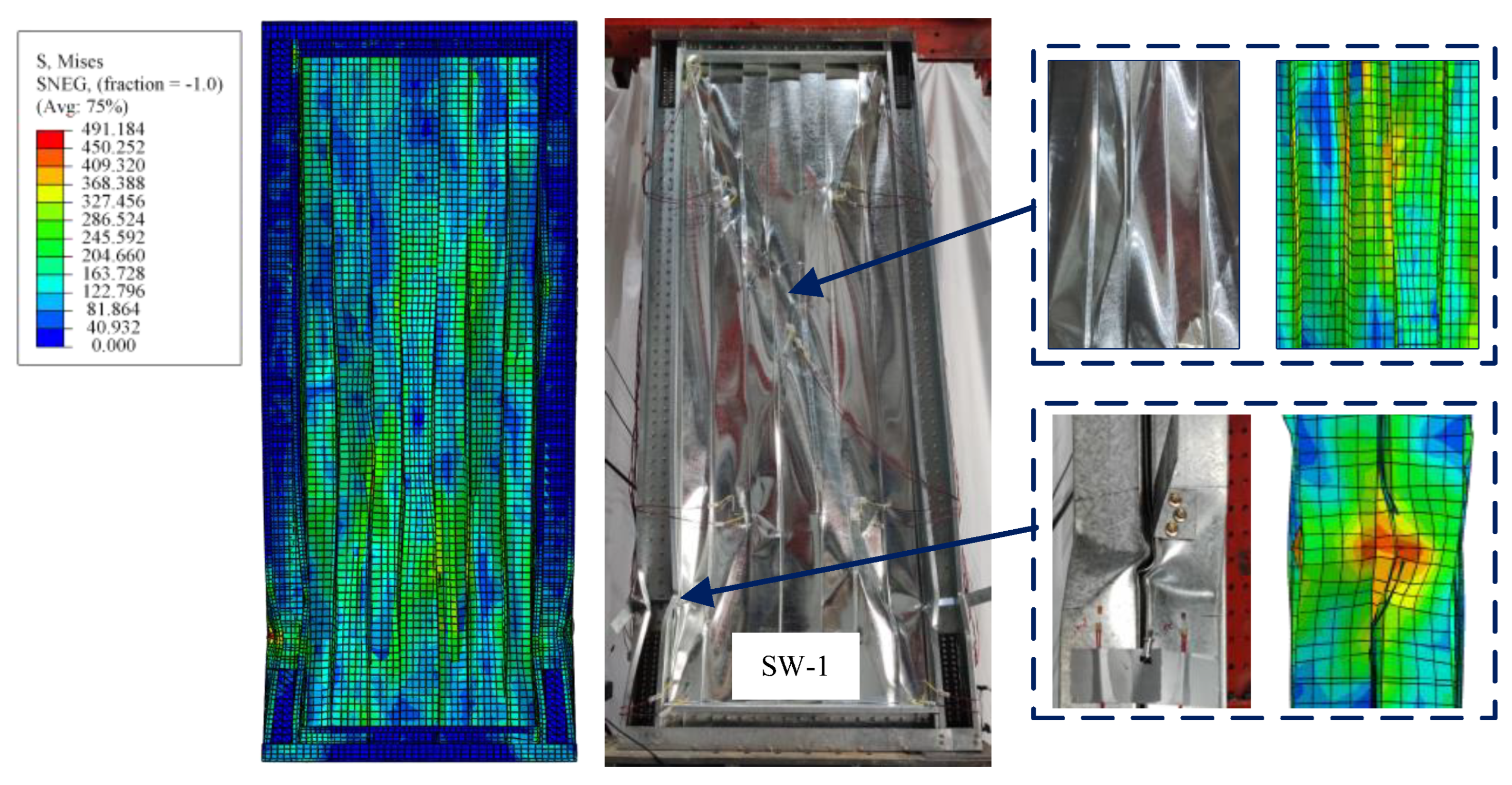
3.2.1. Comparison of Failure Mode

As depicted in Figure 13, the stress concentration in both specimens was primarily located in the compressed side studs (near the bottom hold-downs), which was consistent with the test results. In addition, the tension bands of both corrugated steel sheets were formed along the diagonal of the wall, which was in agreement with the test results. In summary, the failure mode observed in the finite element model aligned with the experimental results, thus validating the method used for modeling the CCS-CFS shear wall.

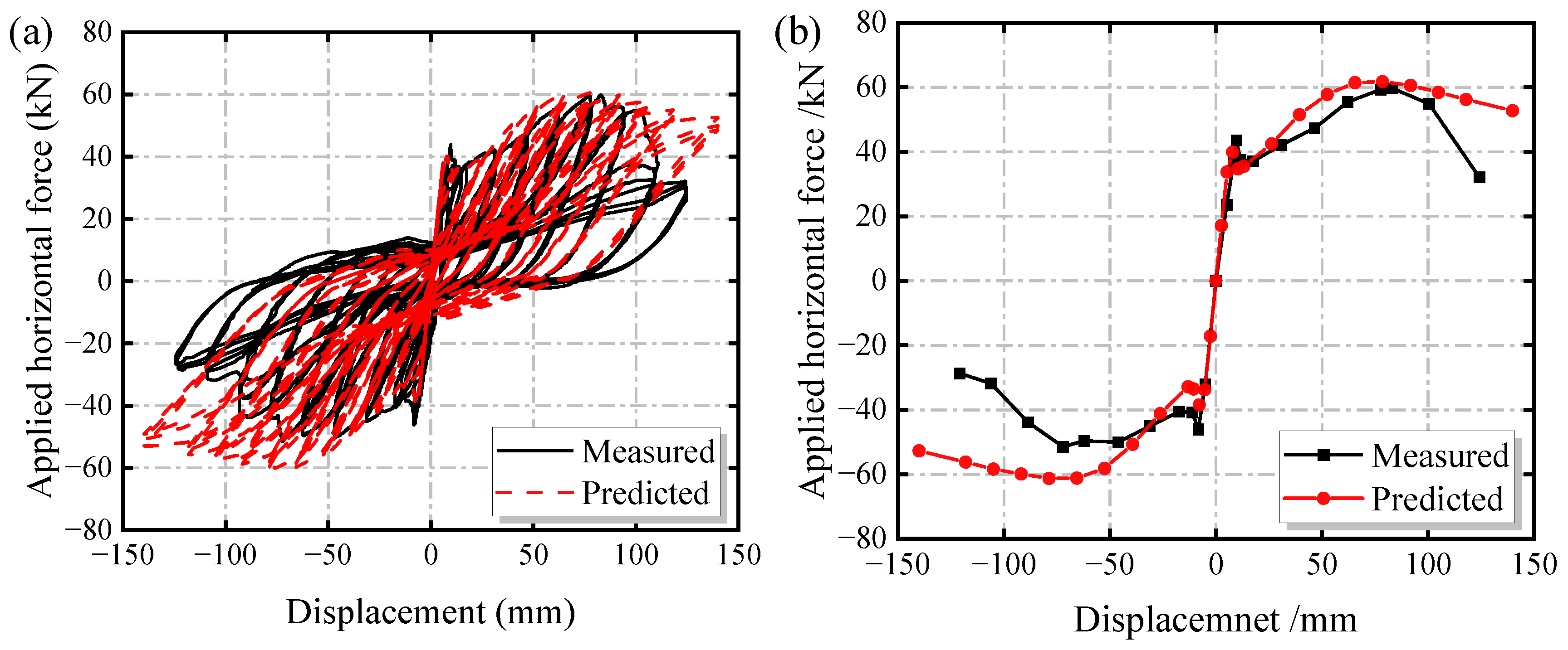
3.2.2. Comparison of Load–Displacement Curve

The test and finite element analysis hysteretic curves are displayed in Figure 14. For specimen SW-1, the hysteretic curve derived from the finite element analysis closely matched the test results, exhibiting a distinct decline section. Compared with the test results, the displacement of the finite element analysis curve in the falling section was larger. This variation could be attributed to the TIE constraint applied in certain connections of the wall, potentially resulting in slightly increased ductility of the shear wall in the simulation compared with the test specimen. However, as can be seen in Table 5, it is evident that the relative error between the test results and the finite element results was maintained within 12%, which meets the requisite standards in the field of civil engineering and enables subsequent parameter analysis.

4. Parametric Analyses

4.1. Influence of Screw Spacing on the Seismic Performance of the CCS-CFS Shear Wall

To investigate the effect of the screw spacing on the seismic performance of the CCS-CFS shear wall, five finite element models were designed with different screw spacings 50 mm, 75 mm, 100 mm, 125 mm and 150 mm [34,35]. The skeleton curves for these models are presented in Figure 15.
As illustrated in Figure 15, the impact of screw spacing on the seismic performance of the shear wall was relatively constrained. The finite element analysis results are listed in Table 6. As detailed in Table 6, when screw spacing increased in the range of 50 mm to 150 mm, the shear strength of the shear wall decreased linearly with a change range of −7.5%. By contrast, the ductility increased linearly in line with the increase in screw spacing, with a change range of approximately 39.7%. This is attributable to the innovative steel frame of the CCS-CFS shear wall, which modified the failure mode observed in conventional CFS shear walls. Consequently, the shear strength of the shear wall primarily relied on the steel frame and the sheet. However, as the screw spacing increased, the number of screws in the tension band of the sheet decreased. This may reduce the connection strength between the sheet and steel frame, while also decreasing the resistance of the screw group, resulting in heightened deformability. Therefore, it is highly recommended that the screw spacing be set at 100 mm to ensure the seismic performance of the shear wall and facilitate construction.

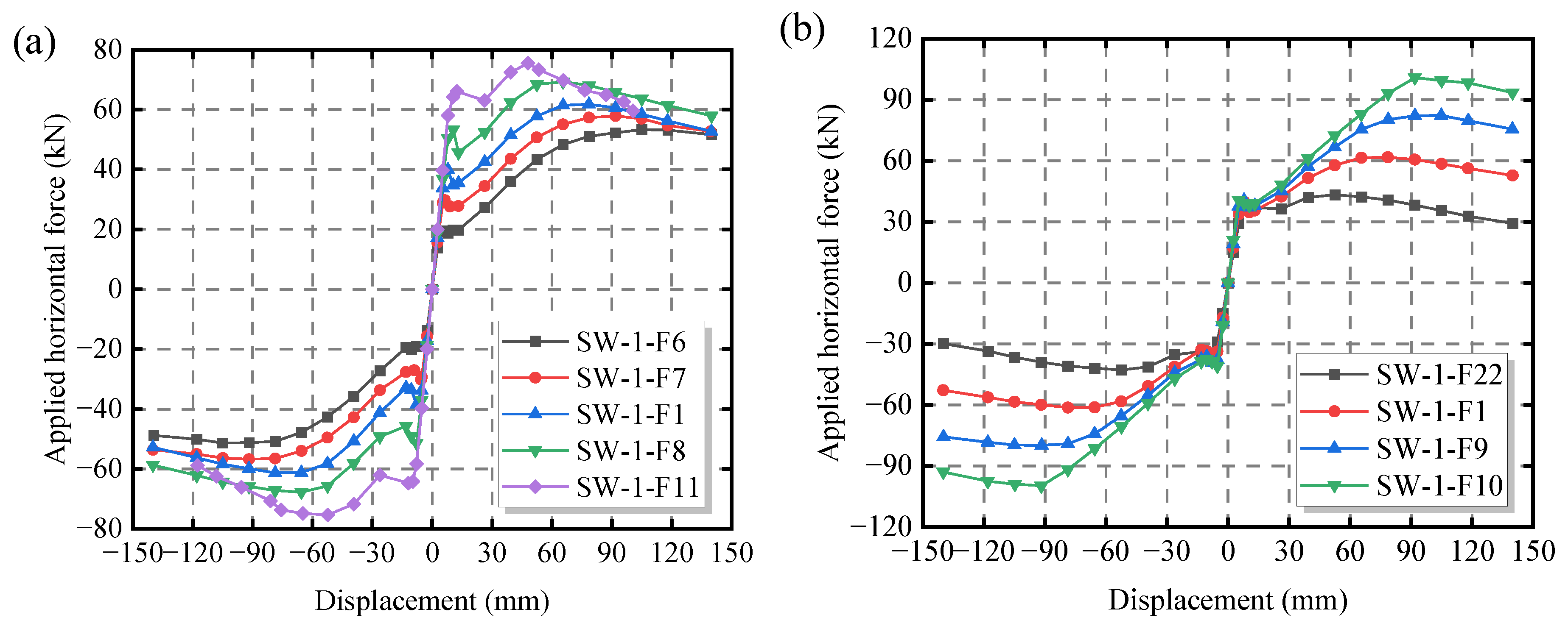
4.2. Influence of Sheet Thickness Ratio on the Seismic Performance of the CCS-CFS Shear Wall

According to the North American specification AISI S100-16 [26], the frame thickness (ts) not be less than the sheet thickness (tp). Referring to the methods for calculating the shear strength of self-tapping screws proposed in this specification, two cases of sheet thickness ratio ts/tp ≥ 2.5 and 1.0 ≤ ts/tp < 2.5 were analyzed. The corresponding parameters and specimen labels are listed in Table 7.
Figure 16 and Figure 17 depict the skeleton curves of models with sheet thickness ratios ts/tp ≥ 2.5 and 1 ≤ ts/tp < 2.5, respectively. As shown in Figure 17, when the sheet thickness ratio ts/tp ≤ 2.0, the shear wall was prone to brittle failure, which should be avoided in practical engineering applications. Therefore, it is suggested that in the structural design, the sheet thickness ratio ts/tp should be greater than 2.0 to ensure the seismic performance of the CCS-CFS shear wall. The simulation results of ts/tp > 2.0 are listed in Table 8. Figure 18 presents the skeleton curves of the models with sheet thickness ratio ts/tp > 2.0.
As detailed in Table 8, when the sheet thickness ratio ts/tp > 2.0 and the frame thickness was fixed and the sheet thickness was increased, the shear strength, shear stiffness, and ductility coefficient of the shear wall correlated positively with the sheet thickness. Conversely, both the yield displacement and maximum displacement correlated negatively with the sheet thickness. The increases in shear capacity, shear stiffness, and ductility coefficient were 41.34%, 44.02% and 35.00%, respectively. Thus, when ts/tp > 2.0, the stiffness and ductility of the shear wall can be effectively improved by increasing the sheet thickness.
However, when the sheet thickness was fixed, the shear strength and maximum displacement of the shear wall correlated positively with the frame thickness. In contrast, the shear stiffness and ductility coefficient exhibited minimal variation. The increases in maximum displacement and shear strength were 75.01% and 133.22%, respectively. Thus, when ts/tp > 2.0, increasing the frame thickness can effectively improve the shear strength and deformation capacity of the shear wall.
In summary, the seismic performance of the CCS-CFS shear wall was significantly influenced by the sheet thickness ratio, with an optimal ratio existing between the frame and the sheet. When ts/tp ≤ 2.0, the shear wall was prone to brittle failure. Therefore, it is suggested that the sheet thickness ratio of the CCS-CFS shear wall should exceed 2.0. When ts/tp > 2.0 and under the same parameters, increasing the frame thickness exerted a more significant impact on the shear strength of the shear wall than increasing the sheet thickness. By contrast, increasing the sheet thickness had a more pronounced effect on enhancing the shear stiffness and ductility of the shear wall compared to increasing the frame thickness.

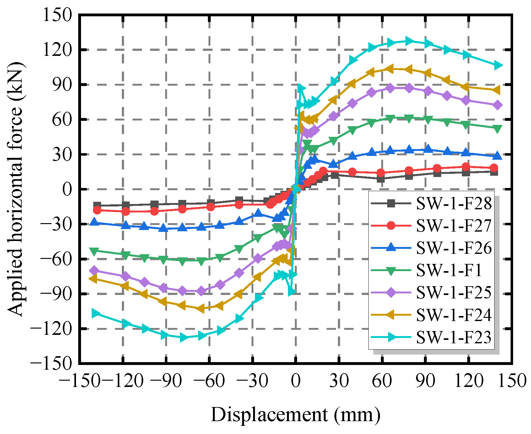
4.3. Influence of Aspect Ratio on the Seismic Performance of the CCS-CFS Shear Wall

The North American specification AISI S400 [36] stipulates that the aspect ratio of a shear wall should not exceed 2. When the ratio is greater than 2:1 and less than 4:1, the shear strength should be reduced by a reduction factor of 2 w/h. However, whether this reduction method that considers the influence of aspect ratio is applicable to the CCS-CFS shear wall is not particularly clear. Therefore, seven finite element analysis models with aspect ratios of 1.08, 1.33, 1.74, 2.50, 3.00, 3.96 and 4.45 were established to study the influence of aspect ratio on the seismic performance of the CCS-CFS shear wall.
Failure modes of CCS-CFS shear walls with different aspect ratios are displayed in Figure 19. As indicated in Figure 19, the stress concentration in both specimens was primarily located in the compressed side studs (near the bottom hold-downs) and the tension band of the sheet. Therefore, the failure mode of shear wall specimens was primarily manifested as distortion buckling of the end stud on the compressive side and buckling of the sheet. When the aspect ratio of the wall increased, the distortion degree of the compression side stud was weakened, and the number of shear deformation half-waves of the sheet was reduced.
Figure 20 depicts the skeleton curves of CCS-CFS shear walls with different aspect ratios. The test and finite element analysis results of shear walls with different aspect ratios are listed in Table 9. When the ratio increased from 1.08 to 4.45, the maximum displacement and shear strength of shear walls changed by −78.84% and 54.17%, respectively.
The relationship between the reduction coefficient of shear strength and the aspect ratio of the CCS-CFS shear wall is illustrated in Figure 21. The reduction factor of shear strength for CCS-CFS shear walls with different aspect ratios is more conservative when determined according to the method recommended by AISI S400. Under reciprocating loading, the shear strength of CCS-CFS shear walls approached unity when the aspect ratio was less than 2.5. To summarize, the effect of aspect ratio on the shear strength of CCS-CFS shear walls can be directly considered using the North American standard AISI S400 [36] and the aspect ratio limit for CCS-CFS shear walls can be relaxed to 10:4.

5. Conclusions

An innovative corrugated steel sheet central sheathed cold-formed steel (CCS-CFS) shear wall was proposed in this paper. Based on this, a refined numerical simulation method for the CCS-CFS shear wall was developed and verified through the cyclic loading test results of two full-size shear wall specimens. Furthermore, a comprehensive finite element analysis was conducted on parameters including screw spacing, sheet thickness ratio, and aspect ratio. The main conclusions are as follows.
(1)
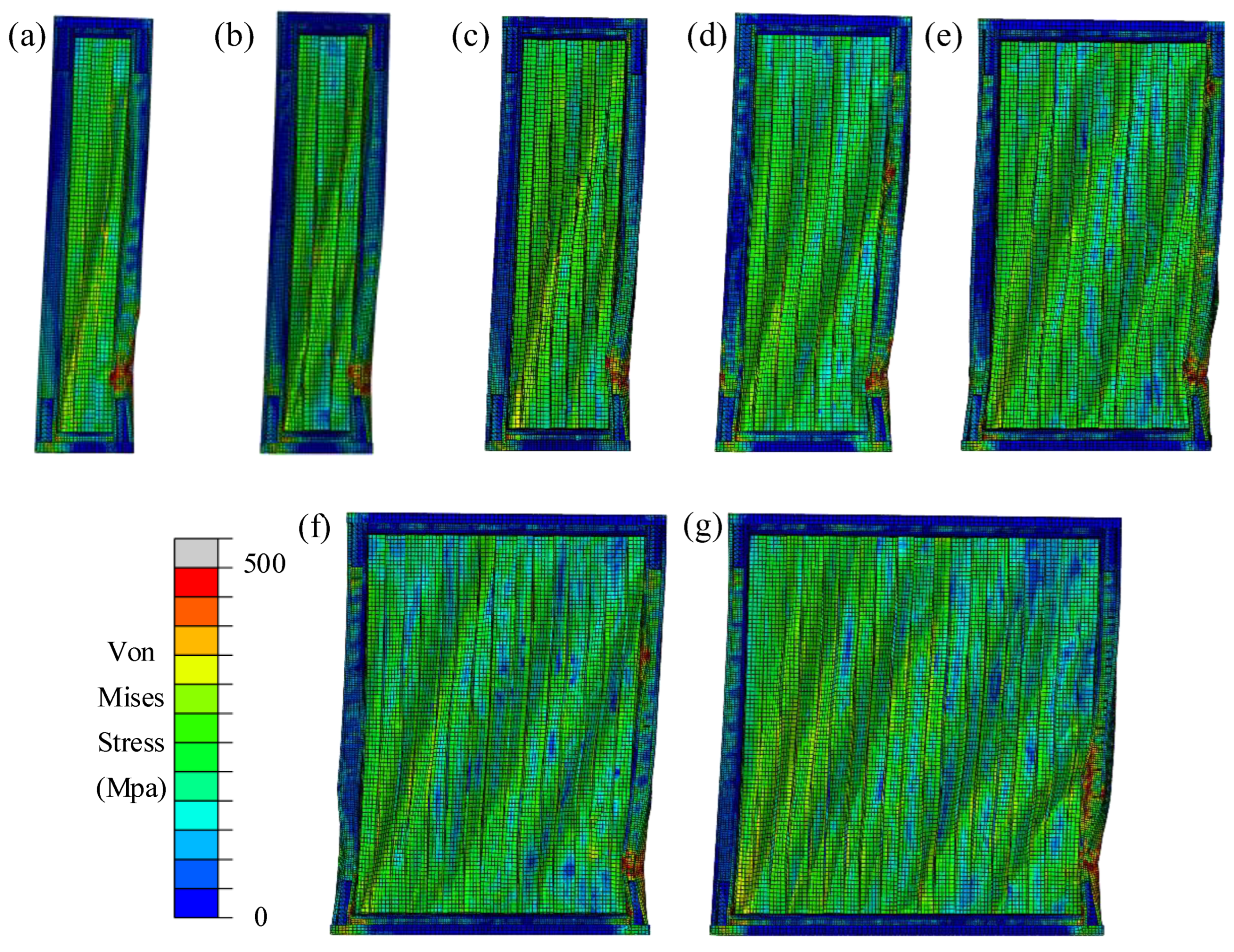
The CCS-CFS shear wall effectively solved the problem of a connection failure between frame and sheet. Under cyclic load, the main failure modes were the plastic buckling of the corrugated steel sheet and the distortional buckling of the end stud. The method of adding a plate to the side stud considerably improved the deformation ability of the shear wall but had limited influence on its shear strength and stiffness.
(2)
Compared with the conventional CFS shear wall, the shear strength, cumulative energy consumption and shear stiffness of the CCS-CFS shear wall were increased by 208%, 175%, and 267%, respectively. Therefore, it is recommended that the CCS-CFS shear wall be employed as a potential lateral force resistance scheme in a multi-layer CFS structure system.
(3)
By considering the characteristics of steel mixed strengthening and metal damage criteria, the detailed numerical simulation of the CCS-CFS shear wall developed in this paper can simulate the real failure mode of a shear wall. Furthermore, the finite element analysis results were in good agreement with the test results.
(4)
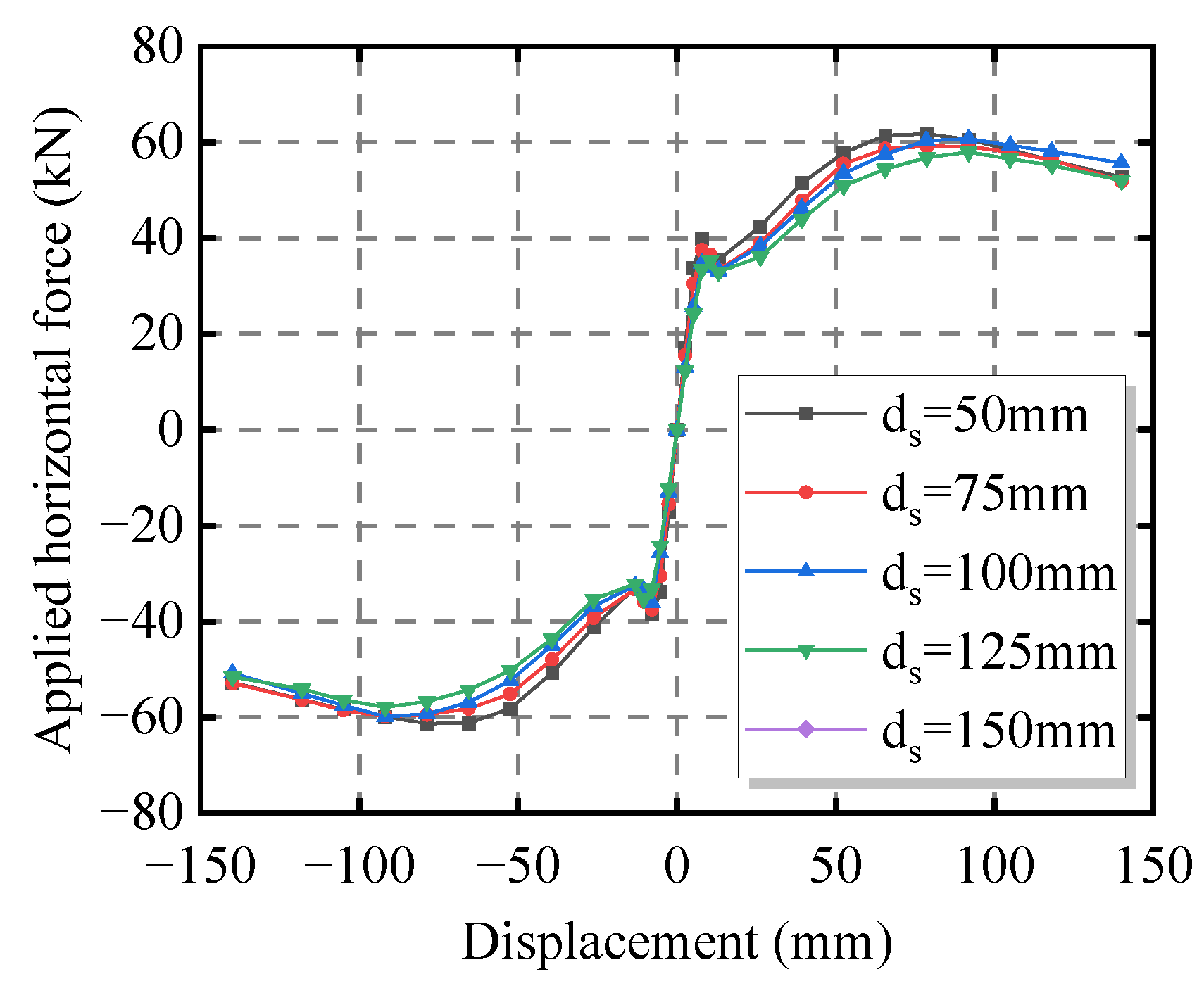
The influence of screw spacing on the seismic performance of the shear wall was relatively limited. Thus, it is highly recommended that the screw spacing be set at 100 mm to ensure the seismic performance of the shear wall and facilitate construction.
(5)
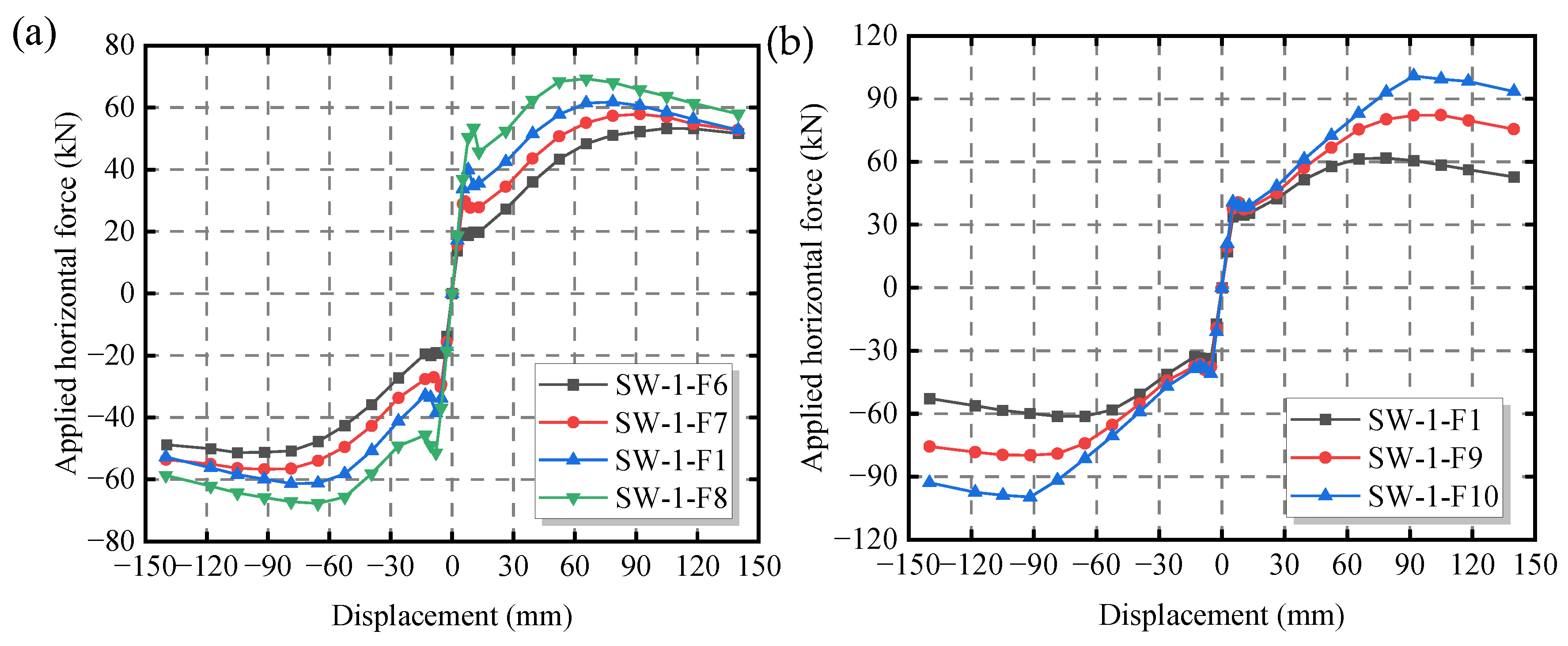
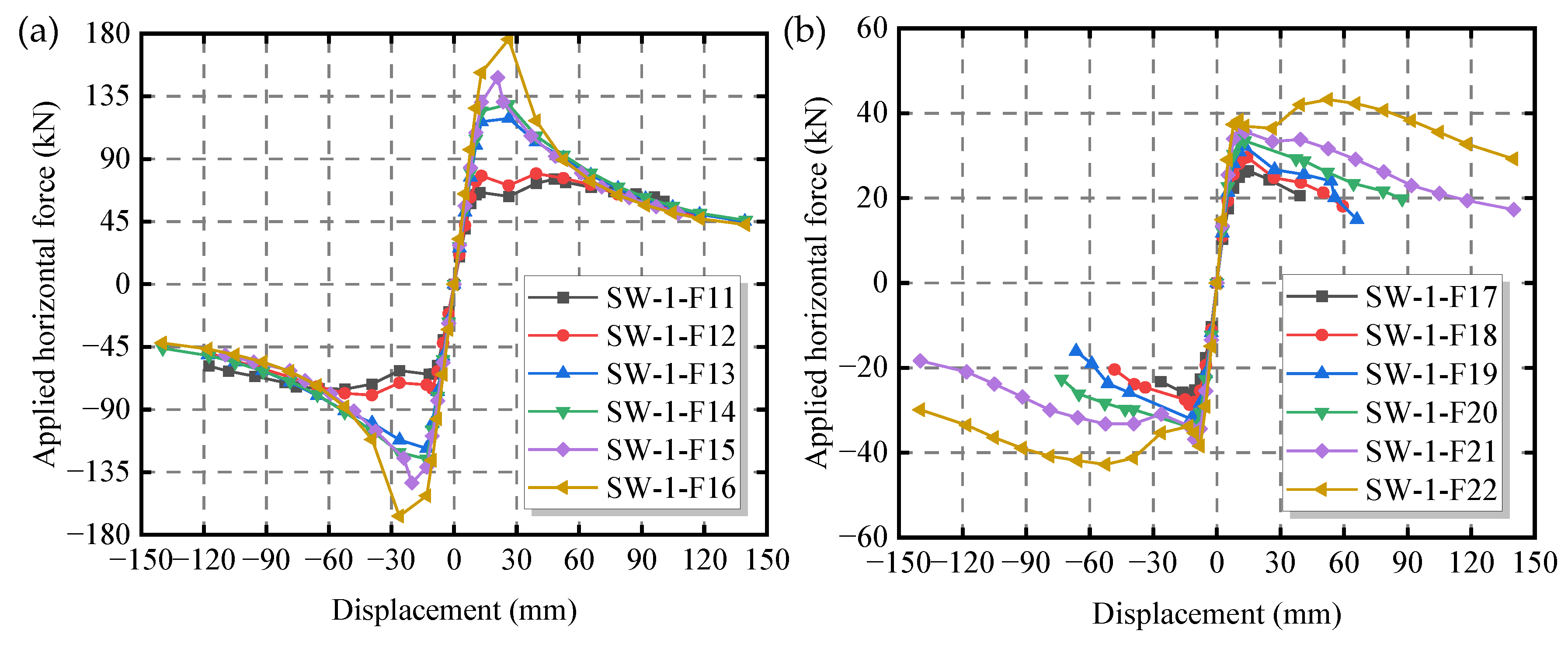
To prevent brittle damage to the wall, it is recommended that the sheet thickness ratio of the CCS-CFS shear wall exceed 2.0. Additionally, increasing the frame thickness can effectively enhance the shear strength of the shear wall, while significantly improving the shear stiffness and ductility of the shear wall can be achieved by increasing the sheet thickness.
(6)
The aspect ratio exerted a significant influence on both the shear strength and maximum displacement of the CCS-CFS shear wall. The impact on the shear strength of the shear wall can be directly assessed by referencing the North American code AISI S400, but its aspect ratio limit can be relaxed to 10:4.

Author Contributions

Methodology, Z.X. and Y.F. (Ying Fan); Software, Y.B.; Validation, X.Z., Y.F. (Yin Feng), D.Z. and L.D.; Data curation, Z.X., Y.B. and C.G.; Writing—original draft, Y.B. and Y.F. (Ying Fan); Writing—review & editing, Z.X., Y.F. (Ying Fan), C.G., X.Z., Y.F. (Yin Feng), D.Z. and L.D.; Visualization, Z.X.; Supervision, Z.X. All authors have read and agreed to the published version of the manuscript.

Funding

This research is supported by the National Natural Science Foundation of China (Grant No. 52008018), and the Program for Scientific Research of Beijing Municipal Education Commission (Grant No. KM202110016012). The research is also partially supported by the Pyramid Talent Training Project of Beijing University of Civil Engineering and Architecture (Grant No. JDYC20220804), the Cultivation project Funds for Beijing University of Civil Engineering and Architecture (Grant No. X23046), the Project funded by China Railway Construction Group Co., Ltd. (Grant No. LX22-21b) and the BUCEA Post Graduate Innovation Project (Grant No. PG2023030). Any opinions, findings, conclusions, or recommendations expressed in this article are those of the authors and do not necessarily reflect the views of the sponsors.

Data Availability Statement

Data is contained within the article.

Conflicts of Interest

Authors Xiangdong Zhang, Yin Feng, Daxing Zhou and Lei Dong were employed by the company China Railway Construction Group Co. The remaining authors declare that the research was conducted in the absence of any commercial or financial relationships that could be construed as a potential conflict of interest.

References

  1. Huang, H.; Yao, Y.; Liang, C.; Ye, Y. Experimental study on the cyclic performance of steel-hollow core partially encased composite spliced frame beam. Soil Dyn. Earthq. Eng. 2022, 163, 107499. [Google Scholar] [CrossRef]
  2. Zhang, H.; Xiang, X.; Huang, B.; Wu, Z.; Chen, H. Static homotropy response analysis of structure with random variables of arbitrary distributions by minimizing stochastic residual error. Comput. Struct. 2023, 288, 107153. [Google Scholar] [CrossRef]
  3. Deng, E.; Wang, Y.; Zong, L.; Zhang, Z.; Zhang, J. Seismic behavior of a novel liftable connection for modular steel buildings: Experimental and numerical studies. Thin-Walled Struct. 2024, 197, 111563. [Google Scholar] [CrossRef]
  4. Yang, L.; Ye, M.; Huang, Y.; Dong, J. Study on Mechanical Properties of Displacement-Amplified Mild Steel Bar Joint Damper. Iran. J. Sci. Technol. Trans. Civ. Eng. 2023. [Google Scholar] [CrossRef]
  5. Wei, J.; Ying, H.; Yang, Y.; Zhang, W.; Yuan, H.; Zhou, J. Seismic performance of concrete-filled steel tubular composite columns with ultra-high performance concrete plates. Eng. Struct. 2023, 278, 115500. [Google Scholar] [CrossRef]
  6. Hasanali, M.; Roy, K.; Mojtabaei, S.M.; Hajirasouliha, I.; Clifton, G.C.; Lim, J.B.P. A critical review of cold-formed steel seismic resistant systems: Recent developments, challenges and future directions. Thin-Walled Struct. 2022, 180, 109953. [Google Scholar] [CrossRef]
  7. Hasanali, M.; Mojtabaei, S.M.; Clifton, G.C.; Hajirasouliha, I.; Torabian, S.; Lim, J.B.P. Capacity and design of cold-formed steel warping-restrained beam–column elements. J. Constr. Steel Res. 2022, 190, 107139. [Google Scholar] [CrossRef]
  8. Deng, R.; Ye, L.; Wang, Y.H.; Li, P.; Shi, Y. Lateral performance of cold-formed steel framed shear walls using slitted sheathing with stiffeners. Eng. Struct. 2024, 302, 117385. [Google Scholar] [CrossRef]
  9. Wu, J.; Rogers, C. Cold-formed steel centre-sheathed (mid-ply) shear walls of intermediate resistance. Thin-Walled Struct. 2023, 188, 110834. [Google Scholar] [CrossRef]
  10. Liu, X.; Zhang, W.; Yu, C.; Li, Y.; Jiang, Z.; Yu, S. Experimental study on cold-formed steel shear walls with different corrugated steel sheathings. J. Constr. Steel Res. 2022, 199, 107639. [Google Scholar] [CrossRef]
  11. Niari, S.E.; Rafezy, B.; Abedi, K. Seismic behavior of steel sheathed cold-formed steel shear wall: Experimental investigation and numerical modeling. Thin-Walled Struct. 2015, 96, 337–347. [Google Scholar] [CrossRef]
  12. Feng, R.Q.; Zhu, B.; Xu, P.; Qiu, Y. Seismic performance of cold-formed steel framed shear walls with steel sheathing and gypsum board. Thin-Walled Struct. 2019, 143, 106238. [Google Scholar] [CrossRef]
  13. Xie, Z.; Zhang, W.; Chen, T.; Zhou, D.; Shi, L.; Tang, Y.; Yu, C. Comparative analysis and design method of shear strength for hybrid SPR-SDS joints in thin-walled steel structures. Structures 2021, 33, 4313–4329. [Google Scholar] [CrossRef]
  14. Xie, Z.; Zhang, A.; Yan, W.; Zhang, Y.; Mu, T.; Yu, C. Study on shear performance and calculation method for self-pierce riveted joints in galvanized steel sheet. Thin-Walled Struct. 2021, 161, 107490. [Google Scholar] [CrossRef]
  15. Rizk, R. Cold-Formed Steel Frame-Steel Sheathed Shear Walls: Improved Range of Shear Strength Values Accounting for Effect of Full Frame Blocking and Thick Sheathing/Framing Members. Master’s Thesis, McGill University, Montreal, QC, Canada, 2017. [Google Scholar]
  16. DaBreo, J.; Balh, N.; Ong-Tone, C.; Rogers, C.A. Steel sheathed cold-formed steel framed shear walls subjected to lateral and gravity loading. Thin-Walled Struct. 2014, 74, 232–245. [Google Scholar] [CrossRef]
  17. Santos, V. Higher Capacity Cold-Formed Steel Sheathed and Framed Shear Walls for Mid-Rise Buildings. Master’s Thesis, McGill University, Montreal, QC, Canada, 2017. [Google Scholar]
  18. Wang, Y.; Gu, C.; Tang, Q.; Shi, Y.; Zhang, H.; Ye, L. Experimental study on seismic behavior of buckling-restrained steel plate shear wall panel element by cold-formed steel with hat-section under pure shear load. J. Build. Struct. 2020, 41, 49–57+64. (In Chinese) [Google Scholar]
  19. Brière, V.; Santos, V.; Rogers, C.A. Cold-formed steel centre-sheathed (mid-ply) shear walls. Soil Dyn. Earthq. Eng. 2018, 114, 253–266. [Google Scholar] [CrossRef]
  20. Yu, C.; Yu, G.; Wang, J. Optimization of Cold-Formed Steel Framed Shear Wall Sheathed with Corrugated Steel Sheets: Experiments and Dynamic Analysis. In Proceedings of the 2015 ASCE Structures Congress, Portland, OR, USA, 23–25 April 2015; pp. 1008–1020. [Google Scholar]
  21. Zhang, W.; Mahdavian, M.; Li, Y.; Yu, C. Experiments and simulations of cold-formed steel wall assemblies using corrugated steel sheathing subjected to shear and gravity loads. J. Struct. Eng. 2016, 143, 04016193. [Google Scholar] [CrossRef]
  22. Ngo, H.H. Numerical and Experiment Studies of Wood Sheathed Cold-Formed Steel Framed Shear Walls; Johns Hopkins University: Baltimore, MD, USA, 2014. [Google Scholar]
  23. Xu, P. Seismic Performance Investigation of New-Type Cold-Formed Steel Framed Sheer Walls with Steel Sheathing; Southeast University: Nanjing, China, 2017. (In Chinese) [Google Scholar]
  24. Yi, J.; Gil, H.; Youm, K.; Lee, H. Interactive shear buckling behavior of trapezoidally corrugated steel webs. Eng. Struct. 2008, 30, 1659–1666. [Google Scholar] [CrossRef]
  25. GB/T228.1-2010; Metallic Materials-Tensile Testing-Part 1: Method of Test at Room Temperature. China Standards Press: Beijing, China, 2010. (In Chinese)
  26. AISI S100-16; North American Specification for the Design of Cold-Formed Steel Structural Members. American Iron and Steel Institute: Washington, DC, USA, 2016.
  27. Xie, Z.; Yan, W.; Yu, C.; Mu, T.; Song, L. Experimental investigation of cold-formed steel shear walls with self-piercing riveted connections. Thin-Walled Struct. 2018, 131, 1–15. [Google Scholar] [CrossRef]
  28. Dassault System Simulia Corp. ABAQUS Analysis User’s Manual Version 6.10; Dassault System Simulia Corp.: Providence, RI, USA, 2010. [Google Scholar]
  29. Schafer, B.W.; Li, Z.; Moen, C.D. Computational modeling of cold-formed steel. Thin-Walled Struct. 2010, 48, 752–762. [Google Scholar] [CrossRef]
  30. Chaboche, J.L. Time independent constitutive theories for cyclic plasticity. Int. J. Plast. 1986, 2, 149–188. [Google Scholar] [CrossRef]
  31. Wang, M.; Shi, Y.; Wang, Y. Equivalent constitutive model of steel with degradation and damage. J. Constr. Steel Res. 2012, 79, 101–114. [Google Scholar] [CrossRef]
  32. Shi, Y.; Wang, M.; Wang, Y. Experimental and constitutive model study of structural steel under cyclic loading. J. Constr. Steel Res. 2011, 67, 1185–1197. [Google Scholar] [CrossRef]
  33. ABAQUS. ABAQUS/Standard User’s Manual. Version 2019; Dassault Systemes Simulia Corp.: Johnston, RI, USA, 2019. [Google Scholar]
  34. JGJ 227-2011; Technical Specification for Construction of Low-Rise Cold-Formed Thin-Walled Steel Buildings. China Architecture and Building Press: Beijing, China, 2011. (In Chinese)
  35. JGJ/T 421-2018; Technical Standard for Cold-Formed Thin-Walled Steel Multi-Storey Residential Buildings. China Architecture and Building Press: Beijing, China, 2018. (In Chinese)
  36. AISI S400-20; North American Standard for Seismic Design of Cold-Formed Steel Structural Systems. American Iron and Steel Institute: Washington, DC, USA, 2020.
Figure 1. Schematic diagram of CCS-CFS shear wall (unit: mm).
Buildings 14 01691 g001
Figure 2. Configurations of specimens: (a) specimen SW-1; (b) specimen SW-2 (unit: mm).
Buildings 14 01691 g002
Figure 3. Failure modes of SW-1: (a) specimen SW-1; (b) corrugated steel sheet.
Buildings 14 01691 g003
Figure 4. Failure modes of SW-2: (a) specimen SW-2; (b) corrugated steel sheet.
Buildings 14 01691 g004
Figure 5. Hysteretic curves of the specimens: (a) specimen SW-1; (b) specimen SW-2.
Buildings 14 01691 g005
Figure 6. Comparison between the CFS shear wall and the CCS-CFS shear wall: (a) CFS shear wall; (b) specimen SW-2; (c) hysteretic curves.
Buildings 14 01691 g006
Figure 7. Finite element model of the CCS-CFS shear wall: (a) schematic diagram; (b) finite element model.
Buildings 14 01691 g007
Figure 8. Material model of steel: (a) isotropic strengthening model of steel; (b) steel dynamic strengthening model; (c) true stress–strain curve of steel tensile.
Buildings 14 01691 g008
Figure 9. Translational and rotational relations of the Cartesian connector: (a) translational connection; (b) rotary connection.
Buildings 14 01691 g009
Figure 10. Tested properties of the screw connection: (a) constitutive model I; (b) constitutive model II.
Buildings 14 01691 g010
Figure 11. Simplified diagram of the hold-downs in finite element model: (a) drawing of the hold-downs; (b) finite element simulation of the hold-downs.
Buildings 14 01691 g011
Figure 12. Cross-sectional dimensions of steel members.
Buildings 14 01691 g012
Figure 13. Comparison of failure modes between the finite element and test for specimen SW-1.
Buildings 14 01691 g013
Figure 14. Comparison of test and finite element load–displacement curves: (a) hysteretic curves; (b) backbone curves.
Buildings 14 01691 g014
Figure 15. Skeleton curves with various screw spacings.
Buildings 14 01691 g015
Figure 16. Skeleton curves with ts/tp ≥ 2.5: (a) the specimen with various sheet thicknesses; (b) the specimen with various frame thicknesses.
Buildings 14 01691 g016
Figure 17. Skeleton curves with 1 ≤ ts/tp < 2.5: (a) the specimen with various sheet thicknesses; (b) the specimen with various frame thicknesses.
Buildings 14 01691 g017
Figure 18. Skeleton curves with ts/tp > 2.0: (a) the specimen with various sheet thicknesses; (b) the specimen with various frame thicknesses.
Buildings 14 01691 g018
Figure 19. Failure modes of CCS-CFS shear walls under different aspect ratios: (a) 4.45:1; (b) 3.96:1; (c) 3.00:1; (d) 2.5:1; (e) 1.74:1; (f) 1.33:1; (g) 1.08:1.
Buildings 14 01691 g019
Figure 20. Skeleton curves with different aspect ratios.
Buildings 14 01691 g020
Figure 21. Relationship between reduction coefficient and aspect ratio.
Buildings 14 01691 g021
Table 1. Coupon test results for CFS components.
ComponentSteel Strength GradeSteel Thickness
t (mm)
Yield Strength
fy (MPa)
Tensile Strength
fu (MPa)
fu/fyElongation
S (%)
Corrugated steelQ2350.72383201.3433.67
Steel frameQ3552.03304331.3123.72
Table 2. Test results.
Specimen
Label
AmplitudeKe
(kN/mm)
Δy
(mm)
Py
(kN)
Δmax
(mm)
Pmax
(kN)
Δu
(mm)
μ
(--)
E
(J)
Ec
(--)
SW-1Positive4.6040.3545.2883.0959.73104.832.602.370.69
Negative6.2820.4841.5472.1951.4488.894.342.090.57
Average5.4430.4243.4177.6455.5996.863.182.230.63
SW-2Positive5.2028.8147.0777.0159.40105.203.652.590.65
Negative5.5232.1039.4789.5051.62120.463.752.610.79
Average5.3630.4643.2783.2655.51112.833.702.600.72
Table 3. Material parameter calibration.
Steel Strength Gradeσ|0
(N/mm2)
Q
(N/mm2)
bisoCkin,1
(N/mm2)
γ1Ckin,2
(N/mm2)
γ2Ckin,3
(N/mm2)
γ3Ckin,4
(N/mm2)
γ4
Q235238211.260501755050120305025100035
Q355330211.280001756800120285035145030
Note: σ|0 represents the stress at zero equivalent plastic strain; Q is the maximum change value of yield surface. biso is the ratio that the yield surface changes with increasing plastic strain. Ckin,k and γk are constants, proofread according to test results.
Table 4. Tested properties of the screw connection.
Connection ObjectConstitutive ModelΔ0.2
(mm)
0.2Pmax
(kN)
Ke
(kN/mm)
Δy
(mm)
Py
(kN)
Δmax
(mm)
Pmax
(kN)
End stud + Corrugated steel0.5111.1362.2262.5534.3767.3715.682
Beam + Corrugated steel0.0470.4649.9100.2141.0131.1682.319
Table 5. Comparison of eigenvalues between the finite element analysis and test results.
Specimen LabelKe
(kN/mm)
Δy
(mm)
Py
(kN)
Δmax
(mm)
Pmax
(kN)
SW-B-1FE analysis5.8133.9647.7978.6061.46
Test5.4430.4243.4177.6456.59
Error (%)6.8011.6310.091.248.61
Table 6. Finite element calculation results under different screw spacings.
Specimen LabelScrew Spacing
(mm)
Yield Displacement
(mm)
Yield Load
(kN)
Maximum Displacement
(mm)
Maximum Load
(kN)
Stiffness
(kN/mm)
Ductility
SW-1-F15033.9647.7978.6061.465.813.50
SW-1-F27535.7647.3578.7460.195.404.13
SW-1-F310042.1146.7691.8759.744.954.21
SW-1-F412542.3945.6091.9057.964.714.71
SW-1-F515042.5045.5491.9257.114.124.89
Table 7. Parameters and numbers of finite element models with different member thicknesses.
Sheet Thickness Ratio
(ts/tp)
Specimen LabelHeight (m) × Width (m)Stud (mm)Track
(mm)
Sheet
(mm)
Remark
ts/tp ≥ 2.54.00SW-1-F63.0 × 1.22.02.00.5The frame thickness is fixed, the sheet thickness is variable.
3.33SW-1-F73.0 × 1.22.02.00.6
2.86SW-1-F13.0 × 1.22.02.00.7
2.50SW-1-F83.0 × 1.22.02.00.8
2.86SW-1-F13.0 × 1.22.02.00.7The sheet thickness is fixed, the frame thickness is variable.
3.57SW-1-F93.0 × 1.22.52.50.7
4.29SW-1-F103.0 × 1.23.03.00.7
1≤ts/tp < 2.52.22SW-1-F113.0 × 1.22.02.00.9The frame thickness is fixed, the sheet thickness is variable.
2.00SW-1-F123.0 × 1.22.02.01.0
1.43SW-1-F133.0 × 1.22.02.01.4
1.33SW-1-F143.0 × 1.22.02.01.5
1.25SW-1-F153.0 × 1.22.02.01.6
1.00SW-1-F163.0 × 1.22.02.02.0
1.00SW-1-F173.0 × 1.20.70.70.7The sheet thickness is fixed, the frame thickness is variable.
1.14SW-1-F183.0 × 1.20.80.80.7
1.29SW-1-F193.0 × 1.20.90.90.7
1.43SW-1-F203.0 × 1.21.01.00.7
1.71SW-1-F213.0 × 1.21.21.20.7
2.14SW-1-F223.0 × 1.21.51.50.7
Table 8. Finite element calculation results under different member thicknesses.
Sheet Thickness Ratio
(ts/tp)
Specimen LabelΔy
(mm)
Py
(kN)
Δmax
(mm)
Pmax
(kN)
Ke
(kN/m)
μ
ts/tp > 2.0SW-1-F656.7844.97104.9853.315.274.00
SW-1-F744.7046.4091.8757.815.404.03
SW-1-F133.9647.7978.6061.735.814.17
SW-1-F826.2352.4165.6269.265.934.99
SW-1-F1119.0163.4252.4675.357.595.40
SW-1-F2216.2436.8152.5043.235.696.10
SW-1-F133.9647.7978.6061.735.814.03
SW-1-F951.1865.7784.8282.266.403.50
SW-1-F1064.0981.8291.88100.827.623.17
Table 9. Parameters and numbers of the finite element model under different aspect ratios.
Specimen LabelAspect RatioΔmax
(mm)
Pmax
(kN)
Shear Strength
(kN/m)
μ
SW-1-F231.0878.21137.5349.514.13
SW-1-F241.3378.75113.0650.474.10
SW-1-F251.7478.7387.1450.494.14
SW-1-12.5078.6061.7351.224.17
SW-1-F263.0091.9434.0033.663.78
SW-1-F273.96118.1119.3425.512.77
SW-1-F284.45137.5615.2322.602.35
Disclaimer/Publisher’s Note: The statements, opinions and data contained in all publications are solely those of the individual author(s) and contributor(s) and not of MDPI and/or the editor(s). MDPI and/or the editor(s) disclaim responsibility for any injury to people or property resulting from any ideas, methods, instructions or products referred to in the content.

