Article

A Fully Prefabricated Pile-Wall Composite Scheme of Open-Cut Tunnel and the Mechanical Behavior of the Composite Structure during Construction

1
Key Laboratory for Urban Underground Engineering of Ministry of Education, Beijing Jiaotong University, Beijing 100044, China
2
School of Civil Engineering, Beijing Jiaotong University, Beijing 100044, China
3
China Railway Siyuan Survey and Design Group Co., Ltd., Wuhan 430063, China
*
Author to whom correspondence should be addressed.
Buildings 2024, 14(6), 1693; https://doi.org/10.3390/buildings14061693
Submission received: 11 April 2024 / Revised: 1 June 2024 / Accepted: 4 June 2024 / Published: 6 June 2024
(This article belongs to the Section Construction Management, and Computers & Digitization)

Abstract

:
In open-cut assembled subway tunnels, foundation pit enclosure piles are typically cast in place. However, this conventional approach limits the functionality of the piles to serving as retaining structures during excavation, resulting in resource inefficiency and the underutilization of prefabrication techniques. To address this issue, a fully prefabricated pile-wall composite scheme is proposed for cut-and-cover tunnels to optimize the retaining effect of the piles and leverage the benefits of prefabricated technology. In this scheme, the retaining pile and lining are both prefabricated. The pile is the temporary retaining structure during pit excavation and a part of the sidewall. This scheme was researched and applied in Jinan, China. Field monitoring and numerical simulation were used to investigate the load transfer within the fully prefabricated pile-wall composite structure (PPWS) and its mechanical response, respectively. The results show: (1) The development of lateral earth pressures on the PPWS experienced three stages. The lateral earth pressure distribution indicates that the PPWS can fully activate the retaining effect of precast piles. (2) Following the backfilling of the joints, the horizontal displacement at the bottom of the precast pile reduced by 0.39 mm. Numerical simulation results indicate the effectiveness of precast pile restraint in PPWS. (3) The PPWS exhibited uniform deformation transition at the joints. The joints play a crucial role in coordinating deformation between the precast piles and sidewalls, utilizing the restraining effect of the precast piles.

1. Introduction

The prefabricated structure has the advantages of fast construction, high efficiency, and environmental protection. Over the past century, prefabricated technology has been increasingly utilized in tunnel and subway station construction worldwide, with notable examples such as the Kyoqiao station and the Platinum station [1,2]. In China, there has been a significant surge in the development of prefabricated metro stations in recent years. Since 2011, many stations across cities like Changchun, Guangzhou, Jinan, Shanghai, Harbin, and Qingdao have been successfully constructed using prefabricated technology [3,4]. There are two types of prefabricated construction methods commonly employed. (1) Fully Prefabricated Lining Structure: Yuanjiadian Station on Changchun Metro Line 2 is a representative example. This station is constructed using fully prefabricated components with grouted tongue-and-groove joints [5]. (2) Prefabricated Composite Structure: The main structures of these stations are composed of prefabricated and a cast-in-place structure, such as Shangchong Park station of Guangzhou Metro Line 11 [6], and Wuzhong Road Metro Station of Shanghai Metro Line 15 [3]. While this composite approach optimizes formwork and efficiency by incorporating prefabricated components, the on-site concrete pouring remains substantial. The assembly rate of this method is approximately 60%, limiting the full benefits of prefabricated technology. Many scholars have researched these prefabricated techniques [7,8,9,10]. Li and Su et al. [7,8] discussed the mechanical properties of this joint based on the full-scale test, focusing on bending and shear properties. The tongue and groove joints used in Yuenjiajian Station have good mechanical properties. Yang et al. explored the failure mode of this type of joint, and provided a suggested stiffness value using a full-scale experiment [11,12,13]. The experimental and numerical analyses were used by Tao and Ding [9,10] to comparatively study the differences in internal force and deformation between the fabricated and cast-in-place structures under seismic effects. The results of the shaking table test shows that the assembled underground structure has better energy absorption performance compared to the cast-in-place structure, but its deformation resistance is weaker [14]. Enclosure structure effectively improves the deformation resistance and joint stiffness of assembled underground structures [15]. Du and Liu et al. [16,17,18,19,20,21] investigated the deformation and mechanical response of fabricated joints connected with grouting sleeves based on the Jinanqiao station.
Although the main structure of the station is fully or partially constructed using prefabricated components with these prefabricated technologies, the envelope structure is still constructed using a cast-in-place and is designed using conventional methods. The bearing capacity of the envelope structure is not taken into account during the operation stage. This design method has two disadvantages: (a) the piles are abandoned after the station construction, which causes resource waste and environmental pollution; (b) the fertilizer tank has to be reserved between the pile and the sidewall, which wastes space and increases the amount of soil excavation. After the construction, the fertilizer tank also needs to be backfilled, which increases the project cost.
The composite wall utilizes the bearing capacity of the envelope structure to reduce the cost of the project [22]. However, the diaphragm wall was conventionally used in enclosures. Both the enclosure and the sidewall are either cast-in-place or the diaphragm wall is directly used as the sidewall [23,24]. At present, the only case of composite wall constructed using precast piles and cast-in-place sidewall is the West Yanmazhuang Station of Jinan rail transit R1 line [25,26]. This station was an island platform station with two floors underground. The length and the span of this station were 356.6 m and 18.3 m, respectively. The excavation depth of the foundation pit was 16.5 m below the ground surface, and its width was about 19.9 m. The high-pressure jet pile was applied outside the prefabricated pile as the water-resisting curtain. After the excavation of the foundation pit, the sidewall was connected with the prefabricated pile through the shear key, as shown in Figure 1. Although precast piles are used as enclosures in West Yanmazhuang Station [25,26], its sidewalls are still cast-in-place. Numerous investigations have explored the mechanisms of force transfer and load bearing in traditional cast in situ composite structures [23,24]. However, this method of construction does not take full advantage of prefabrication technology.
In order to fully utilize the advantages of prefabrication technology and to take advantage of the retaining effect of the enclosure structure, this paper proposes the fully prefabricated pile wall composite structure (PPWS) for the cut-and-cover tunnel, including the composite scheme, the layout plan of the prefabricated pile, the components of the tunnel structure, and the connection method of the PPWS.
In addition, unlike cast-in-place composite structures, the PPWS requires an assembly gap between the precast piles and the sidewall. The piles are connected to the sidewall with joints. Due to its special structural characteristics, the mechanical properties of the PPWS remain ambiguous. Previous research has focused on the tunnel lining [27,28,29,30,31]. The research on the construction mechanical behavior of the PPWS and the role of the joints between precast piles and the main structure are still rare. To address these problems, on-site monitoring is used to explore the earth pressure transfer of the PPWS, and numerical simulation is used to analyze the mechanical response of the PPWS and the pivotal role of joints.
This paper provides a basis for the design and promotion of the application of the PPWS to promote the development of the prefabrication and utilization of enclosure structures.

2. Project Overview

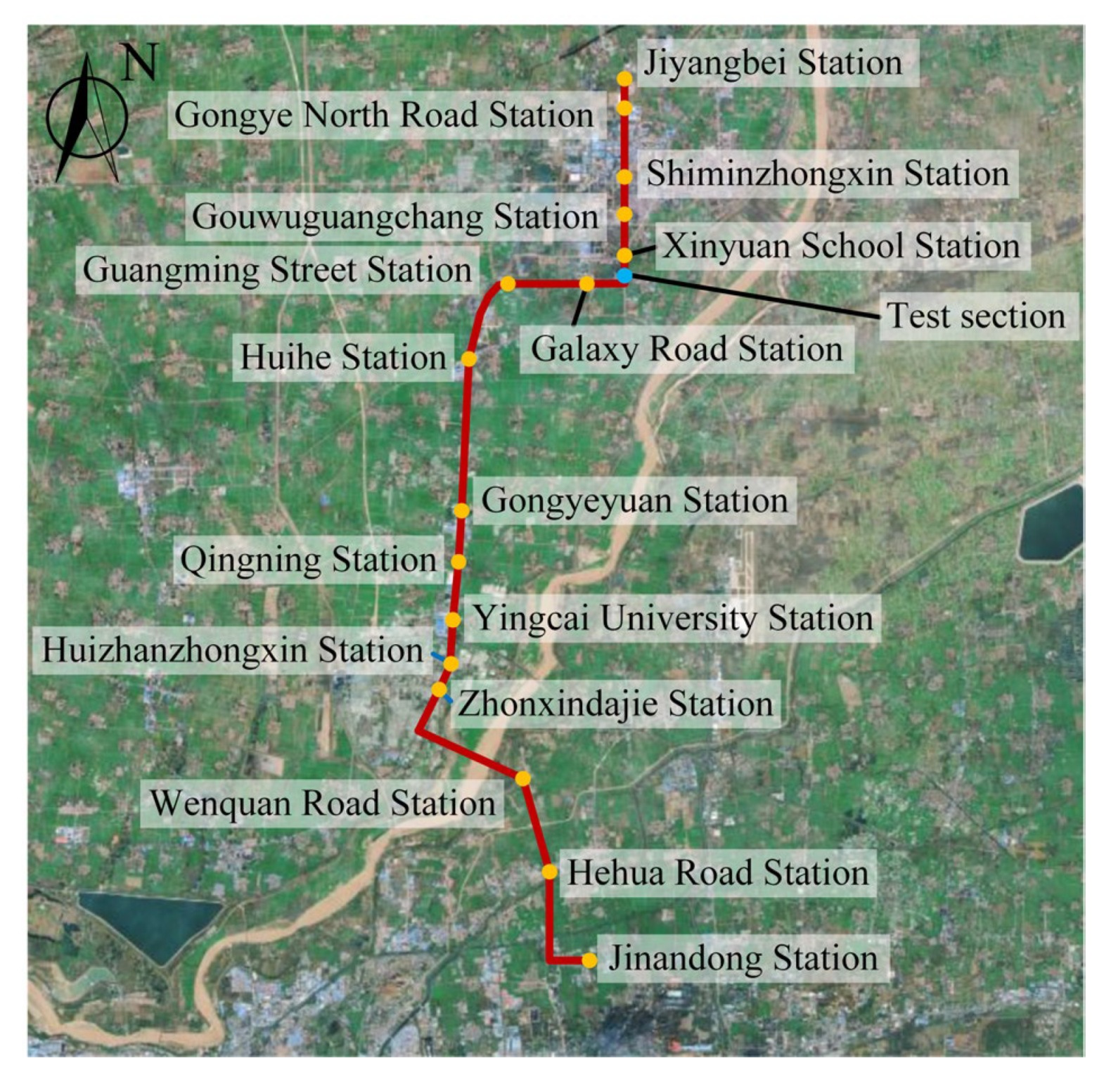
2.1. Project Background
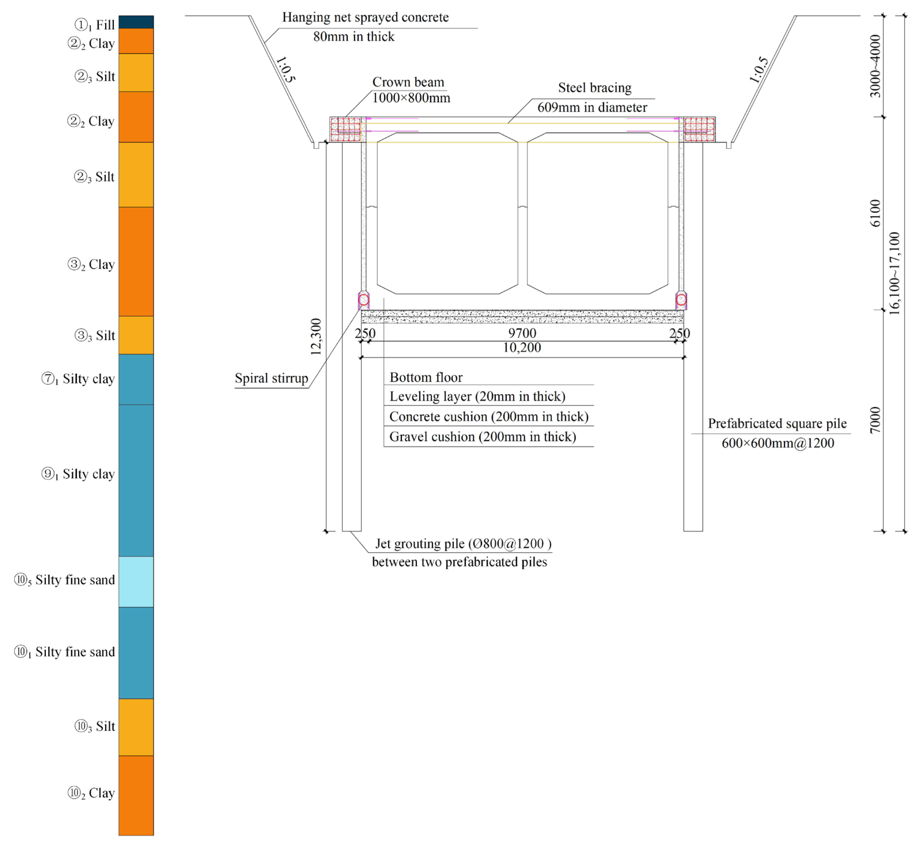
The Jiyang tram project in Jinan spans from Jinandong Station to Zhongxindajie Station. The total length of the line is about 35.5 km, of which the underground section constructed using the open-cut method is 16.4 km. The main structure of the underground section is a single-story double-span reinforced concrete frame structure. A specific 200 m of the underground section is selected as the test section for the implementation of the PPWS. The test section is situated between Galaxy Road Station and Xinyuan School Station. In this test section, the depth of the bottom plate is 9.2–10.2 m, and the soil covering of the top plate is 3–4 m. The site of the test section is shown in Figure 1.

2.2. Site Condition

Figure 2 displays the typical geological profile of the project. The strata in this project was composed of fill, clay, silt, silty clay, and silty fine sand. According to the soil profile, the junction location of the text section is mostly silt, clay, and silty clay. The long-term phreatic water level is 4.6 m.

3. Scheme of PPWS for Open-Cut Tunnel

3.1. Envelope Structure System

As an envelope structure, 600 mm × 600 mm precast square piles with a spacing of 1200 mm were used. The crown beam aligns with the top slab of the precast lining, featuring a 600 mm × 740 mm × 500 mm cast-in-place area. During the foundation pit excavation, internal support is provided by steel supports with specifications of Φ 609 mm diameter, 16 mm thickness, and 3600 mm spacing. According to the differences in environmental conditions and stratum characteristics around the tunnel, the open-cut foundation pit is supported by slope + soil nail support and steel sheet pile support, respectively. The cross-section of the tunnel constructed using PPWS is shown in Figure 3.

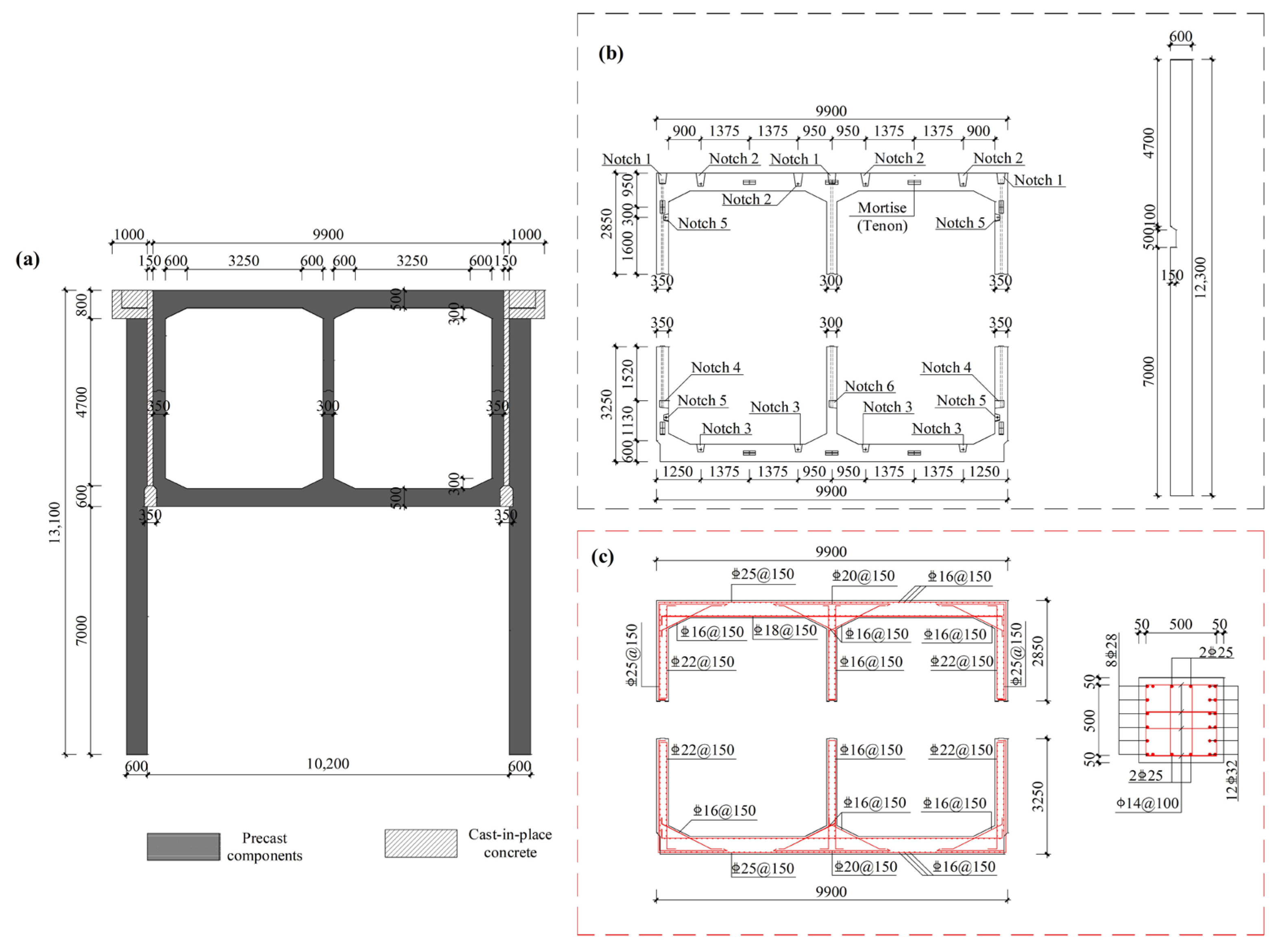
3.2. Main Lining Structure

The main lining structure is composed of two precast components: the M component and W component, as depicted in Figure 3. The height of the M and W components is 2.85 m/3.25 m. The longitudinal joints between the M and W components are assembled using staggered joints. A mortise–tenon joint is adopted in assembly-lining structures. After assembly, prestressed tendons are utilized to connect the M and W components into a ring lining. The top plate is covered with soil for 4 m. The outer frame dimensions of the tunnel section are 9.9 m (width) × 6.1 m (height), and the standard length of each ring is 2.4 m. Mortise–tenon joints and prestressed tendons are also employed in the connection between rings.

3.3. Connection between Precast Pile and Sidewall

For the cast-in-place structure, the retaining pile can be completely close to the sidewall, but the retaining pile and lining structure of this project are prefabricated structures. Due to errors in pore-forming and the installation location of the prefabricated pile, an assembly gap was reserved between the prefabricated pile and the prefabricated sidewall. The crown beam is linked to the top of the sidewall, while the prefabricated pile is connected to the bottom of the sidewall. Figure 4 illustrates the connection method between the precast pile and the sidewall.
The assembly method is summarized as follows:
A 100 mm × 500 mm notch was reserved at the bottom of the sidewall (SWN). The longitudinal bar of W component was exposed in the notch. The precast pile also reserved a notch (PPN) and exposed the longitudinal bar. Then, SWN and PPN were connected through spiral stirrups with the size of C14@150 mm and 4 Փ10 inserted bars. The joint B would be backfilled with C50 concrete after completion of the assembly.
A 600 mm × 740 mm × 500 mm cast-in-place area and sleeve were reserved at the crown beam and the top of the sidewall, respectively. After the prefabricated lining was positioned, the connection bar was connected to the sleeve and bound with the reserved reinforcement of the crown beam. The assembly gap was backfilled with C20 concrete after reinforcement binding, and then we filled joint A with C50 concrete.

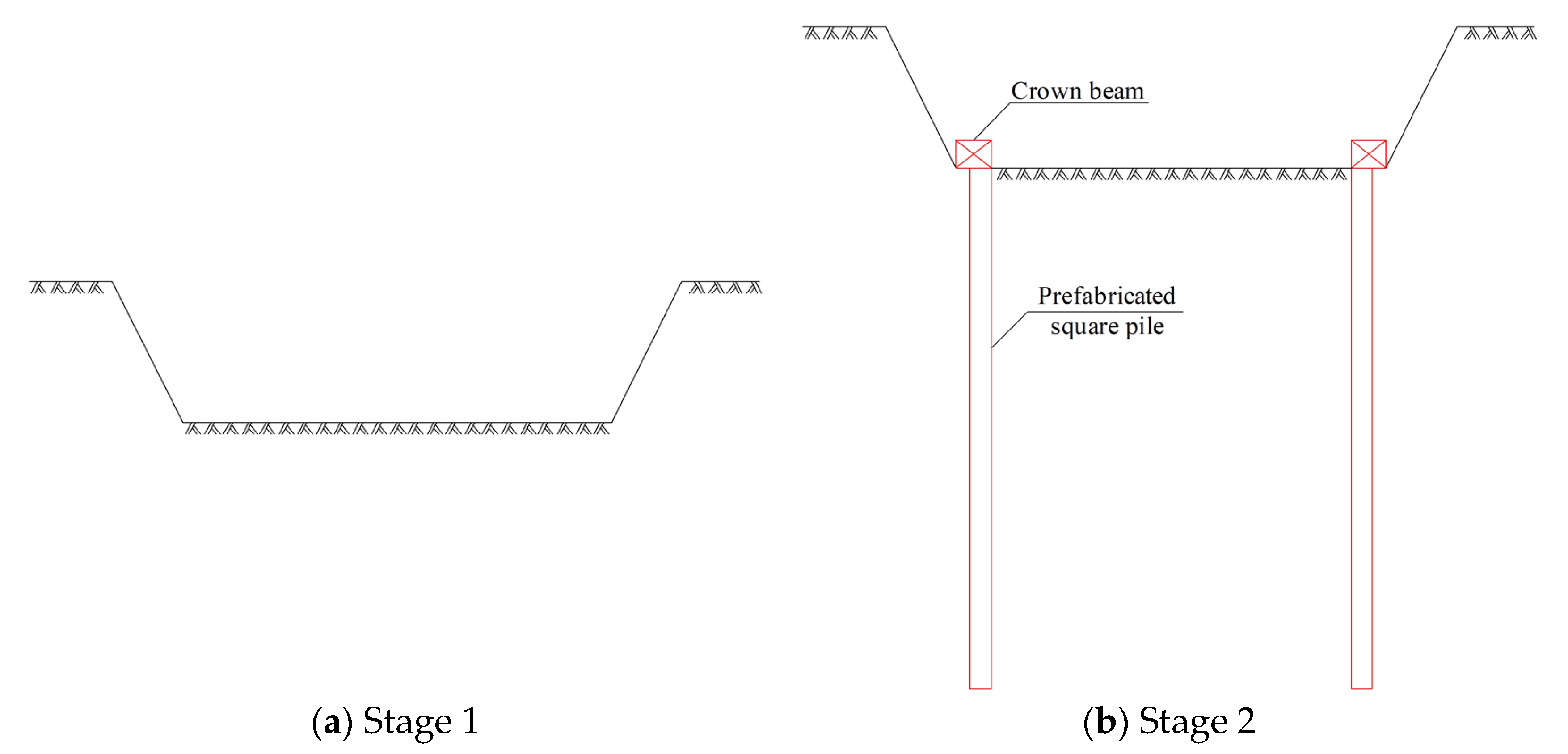
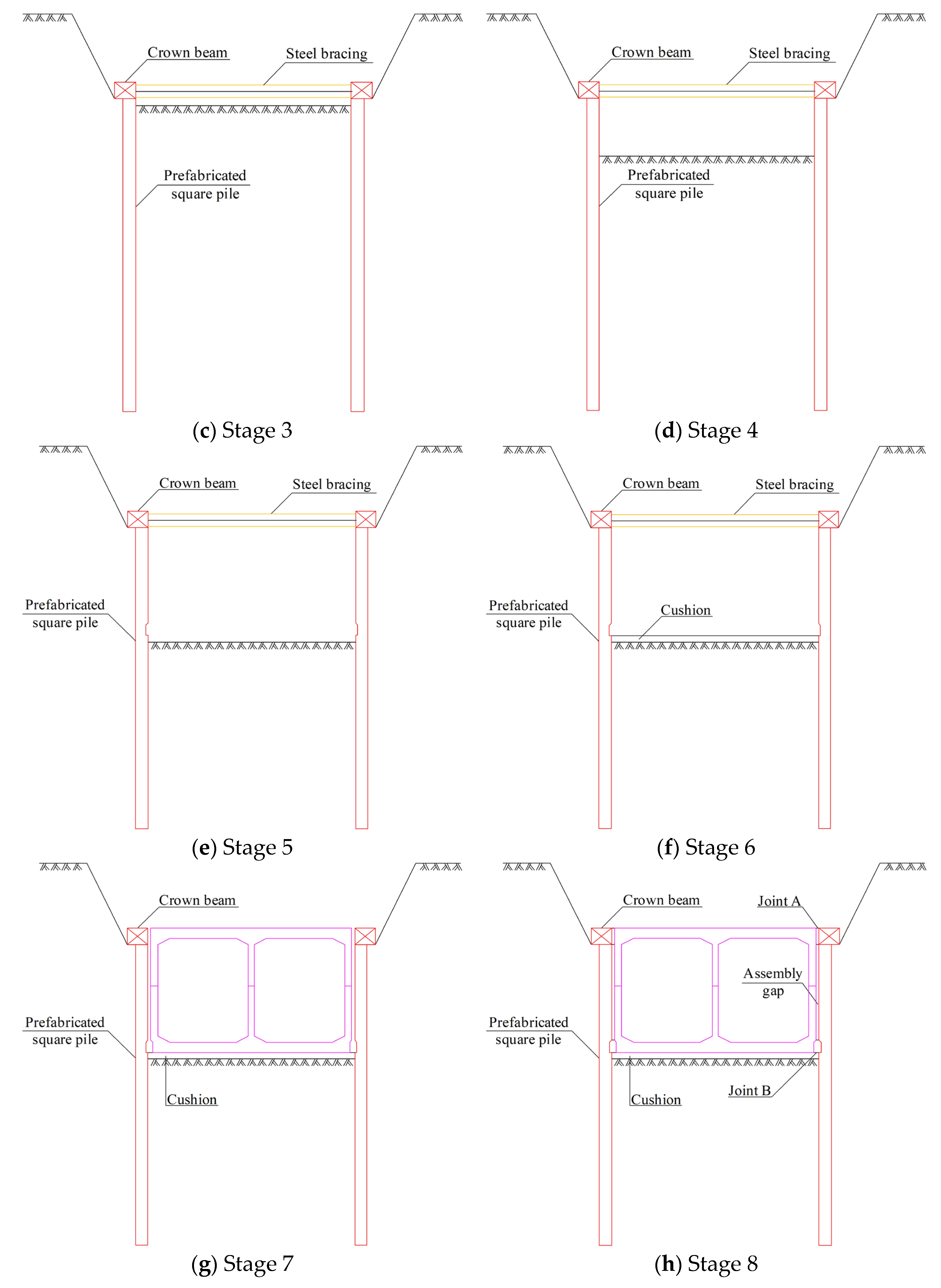
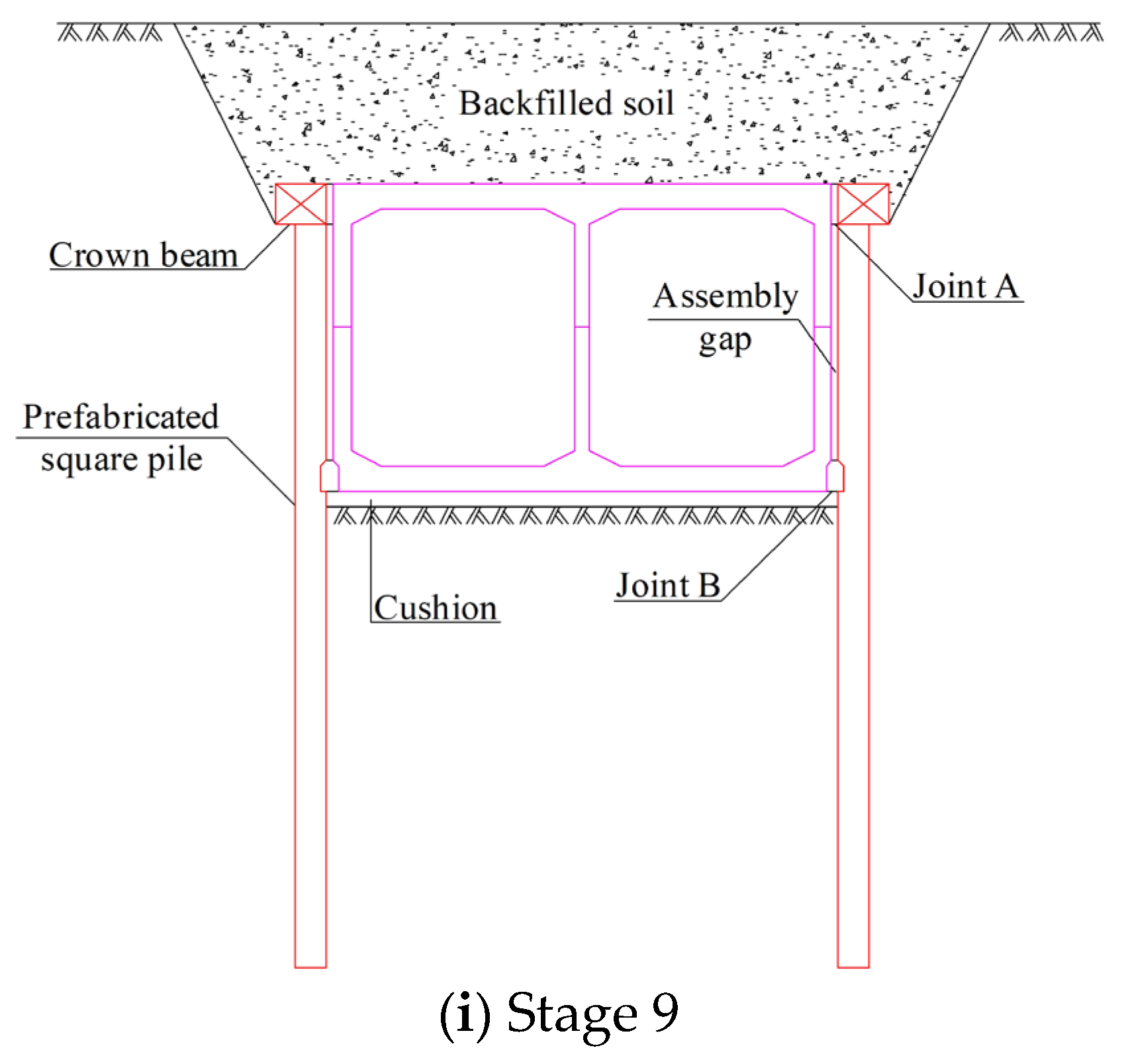
3.4. Assembly Process of Prefabricated Structure

The assembly process of the prefabricated structure is summarized in the following stages, as shown in Figure 5. Stage 1: Grading excavation and constructing 80 mm of the hanging net sprayed concrete with C20 concrete. Stage 2: Excavate the foundation pit to the crown beam level and construct the crown beam and precast piles. Stage 3: Excavate the foundation pit to 0.5 m below the steel supports and construct steel supports. Stage 4: Using the bench method for excavation, the first step is to excavate to 6.5 m. Stage 5: Excavate to the bottom of the pit. Stage 6: Construct a 200 mm gravel cushion and 200 mm concrete cushion and make level for assembly preparation. Stage 7: Hoist the W component in place after removing the steel supports, followed by hoisting the M component. The M and W components were assembled using the tongue and groove joints. Prestressed tendons were tensioned through notches that connect the M and W components. Stage 8: Backfill the assembly gap with C20 concrete after filling joint B with C50 concrete, then filling joint A with C50 concrete. The connection of the lining to the precast piles is described in Section 3.3. Stage 9: Backfill the crown and cover the soil to restore the ground to the design elevation.

4. Earth Pressure Transfer in PPWS

In order to investigate whether the PPWS can fully utilize the retaining effect of prefabricated piles, on-site monitoring was conducted on the lateral earth pressure of the PPWS.

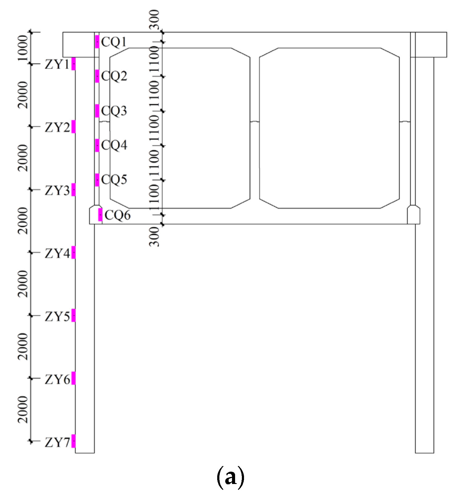
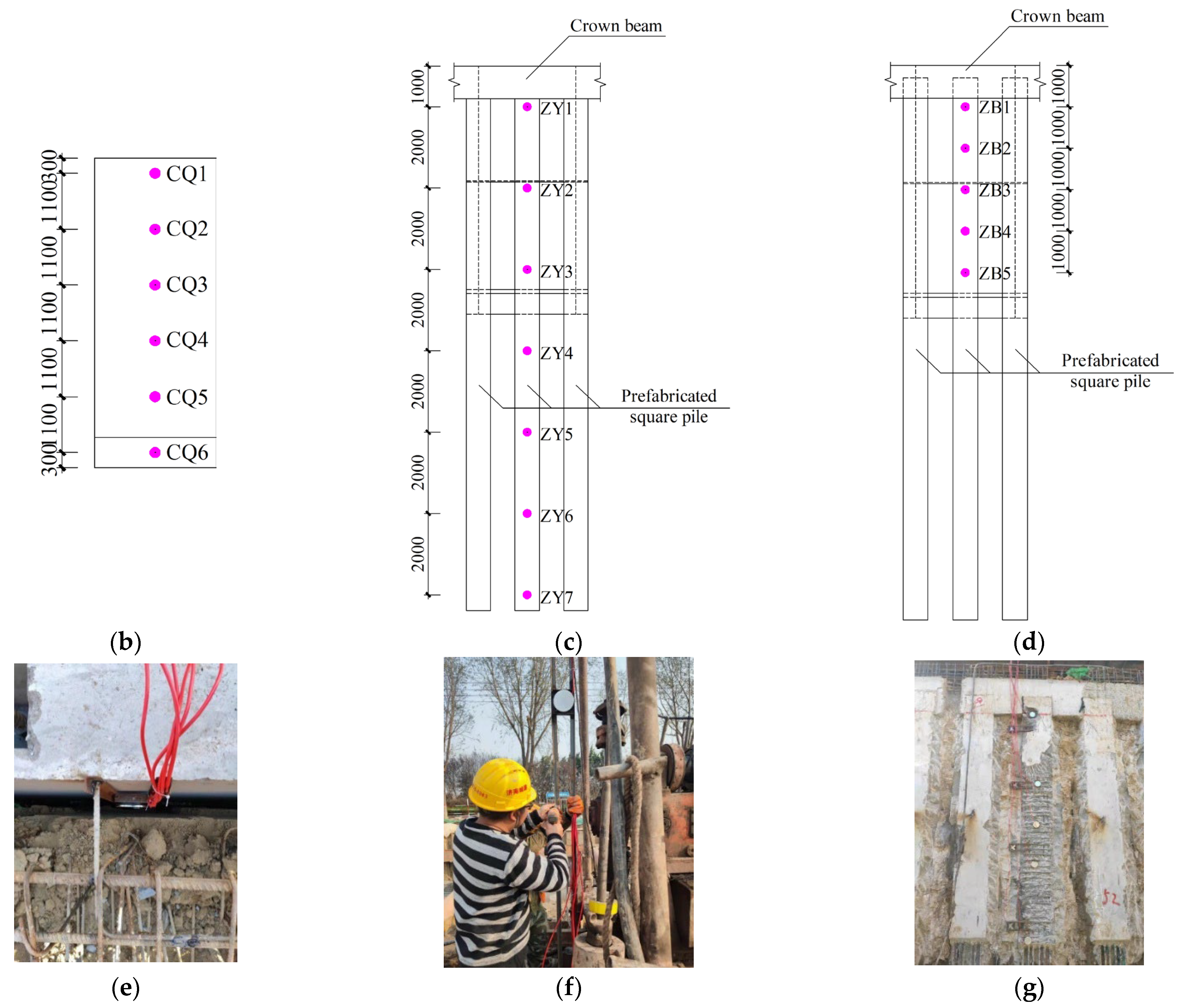
4.1. Layout of the Monitoring System and Monitoring Scheme

Two monitoring sections were selected for on-site monitoring. Each monitoring section including a prefabricated pile and a ring tunnel lining. The positions of each earth pressure measuring point are illustrated in Figure 6.
The earth pressure transducers on the soil-facing (ZY1-ZY7) and back (ZB1-ZB5) sides of the prefabricated pile were used to monitor the lateral earth pressure borne by the prefabricated pile and the lateral earth pressure transmitted to the tunnel lining, respectively. The spacing between the pressure transducers on the soil-facing side was 2.0 m, while the pressure transducers on the soil-facing side were 1.0 m. The pressure transducers with a spacing of 1.0 m on the outer surface of the sidewall (CQ1-CQ6) were employed to monitor the lateral soil pressure borne by the tunnel lining. Monitoring of the earth pressure on the facing soil of the pile began once the precast piles were constructed. After the assembly gap and joints were backfilled, the earth pressure on the pile’s back soil side and the sidewall’s outer side were measured. Monitoring once a day ceased when the soil pressure on the outside of the lining sidewall stabilized.

4.2. Monitoring Data Analysis

The results of the two monitoring sections are similar. Due to some invalid measurement points in the second monitoring section during construction, the results from the first monitoring section were selected for analysis.

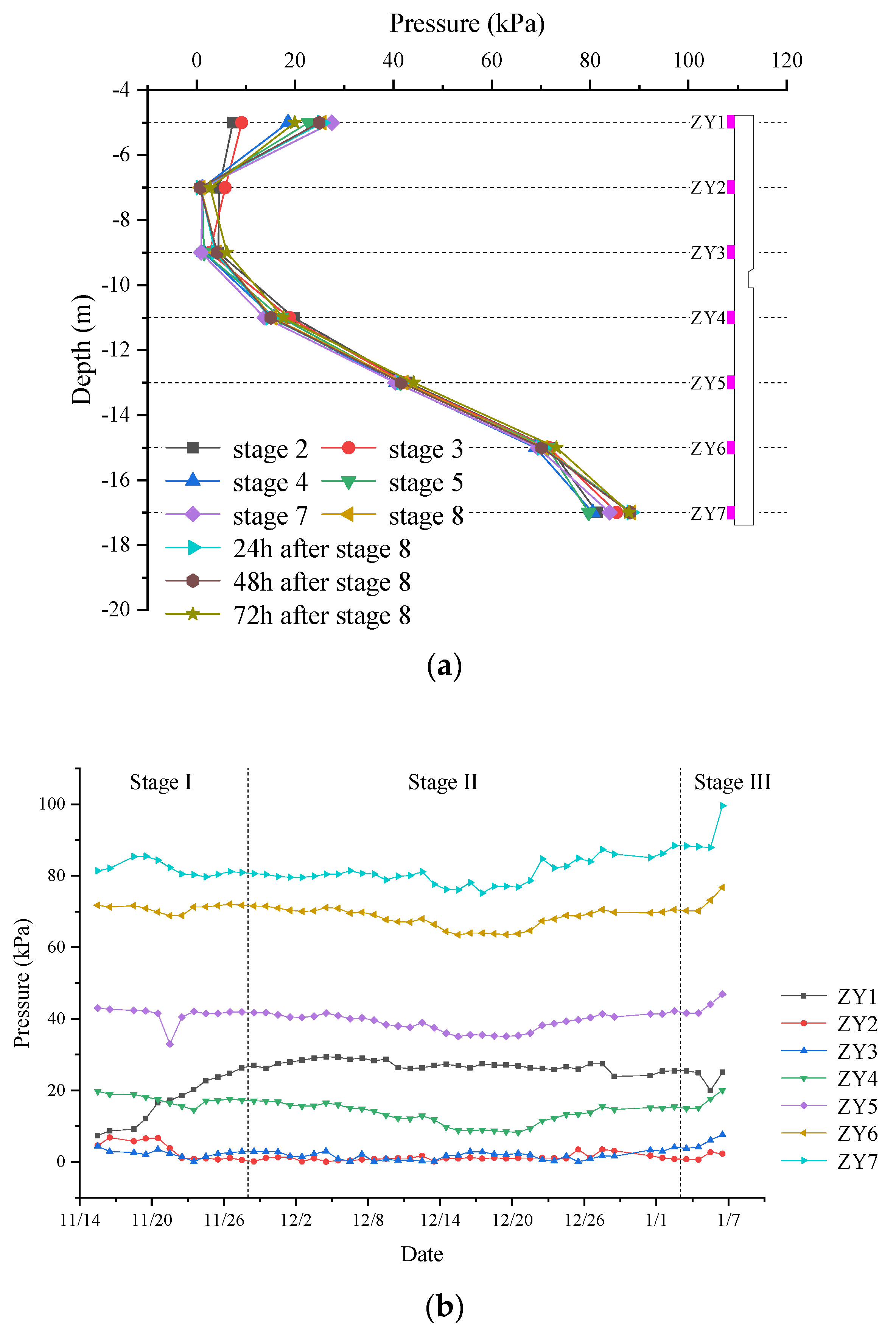
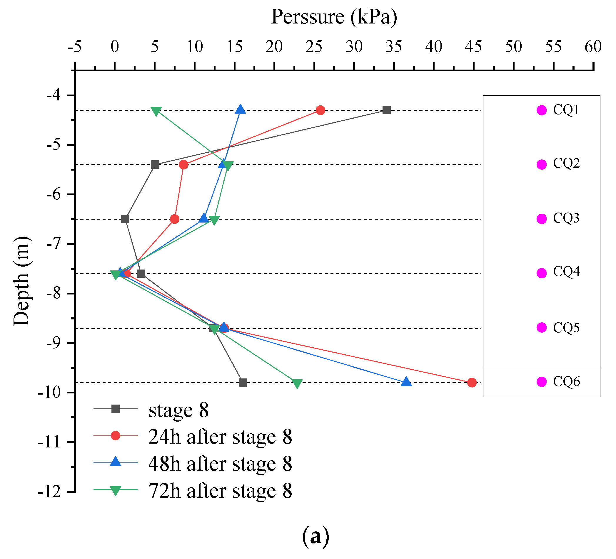
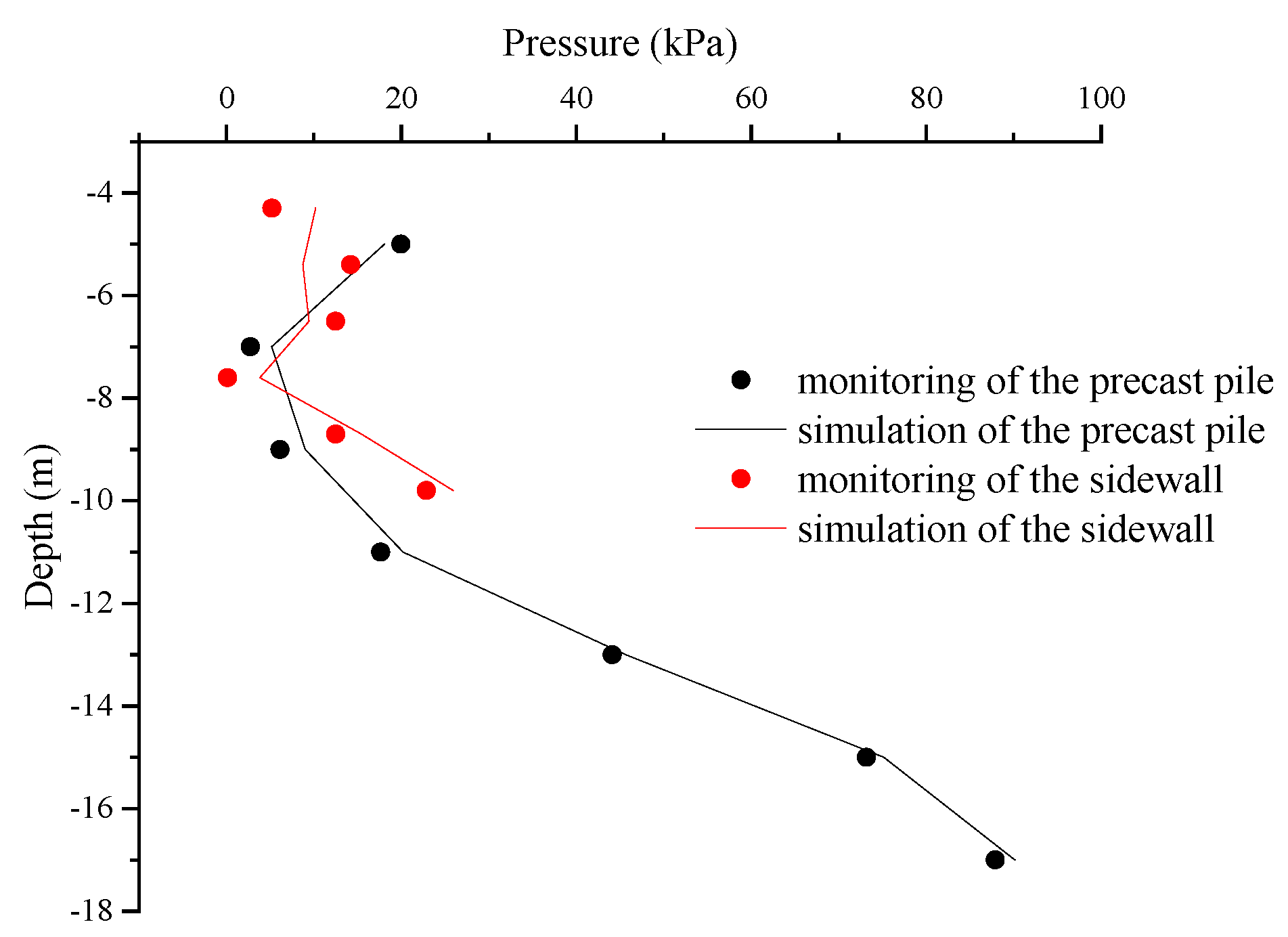
4.2.1. Earth Pressure on the Facing Soil Side of the Prefabricated Pile

The variation law of earth pressure on the facing soil side of prefabricated piles was analyzed. The distribution of earth pressure on the facing soil side at different construction stages, and its variation curve with time are shown in Figure 7.
  • The earth pressure on the facing soil side of prefabricated piles was distributed in a “C” shape, with higher pressures at the top and bottom compared to the middle of the pile. The earth pressure at the top and bottom of the pile was 9.15 kPa and 85.34 kPa, respectively.
  • The earth pressure at the top of the pile gradually increased to a maximum value of 22.70 kPa before the removal of steel supports, decreasing after the backfilling of the assembly gap. The steel supports provided reliable support to the precast piles during excavation. After the assembly gap was filled, a stable connection was established between the precast pile top and the sidewall. The precast piles and the sidewall shared the earth pressure as PPWS.
  • Based on monitoring data, three stages of earth pressure development were identified during construction. Stage I (pit excavation): The excavation of the foundation pit resulted in the earth pressure at the top of the pile increasing to 26.34 kPa. The earth pressure at the pile body gradually decreased and eventually stayed near 0. The earth pressure at the bottom of the pile remained above 80.0 kPa. Stage II (lining construction): The earth pressures remained stable. Stage III (PPWS formation): The earth pressure in the middle of the pile increased by 1.92–5.65 kPa, while the top and bottom of the pile decreased by 0.52 kPa and 5.50 kPa, respectively. Once the joints were filled, lining provided support and restraint to the precast piles through the joints. The precast piles eventually formed PPWS with the tunnel lining and carried the external loads.
Figure 7. Earth pressure on the facing soil side of the prefabricated pile; (a) Earth pressure under different construction stages; (b) Earth pressure during construction.
Buildings 14 01693 g007

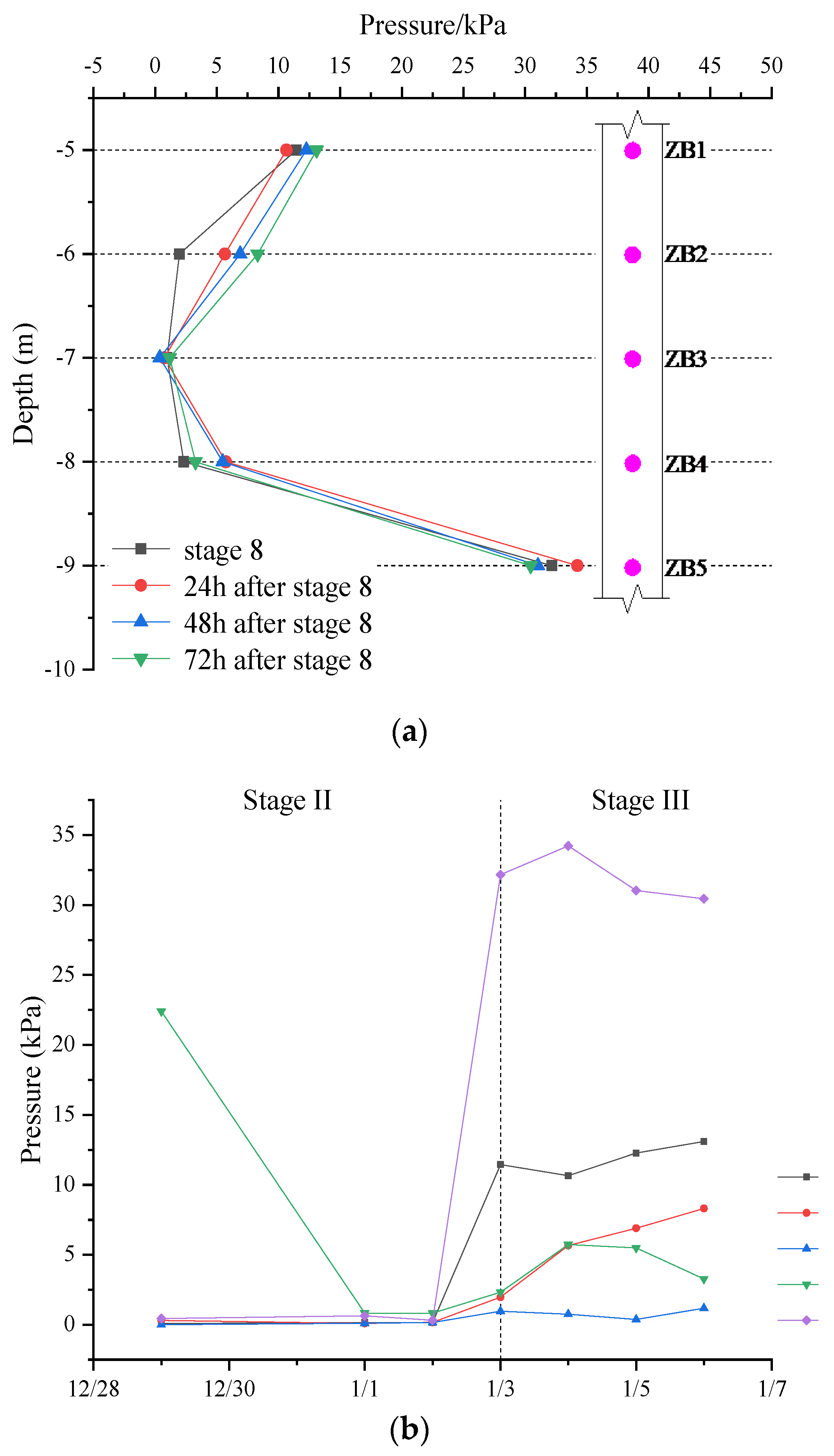
4.2.2. Earth Pressure on the Facing Soil Side of the Prefabricated Pile

The earth pressure on the facing soil side of prefabricated piles after joints were filled, and its variation curve with time are shown in Figure 8.
  • The earth pressure on the back soil side of prefabricated piles was distributed in a “C” shape. The earth pressure at the connection point between the prefabricated piles and the lining exhibited relatively higher values compared to other locations, indicating the effective transfer of external loads by the joints.
  • In comparison to the earth pressure on the facing soil side of the precast pile, the earth pressure on the back soil side was generally lower, except for the middle section of the pile body. The earth pressure on the facing and back soil sides of the precast piles is shown in Table 1. The PPWS fully utilized the retaining effect of precast piles, leading to a decrease in earth pressure on the back soil side of the upper part of the piles by 1.56 kPa to 6.85 kPa. After the joints were filled, the lining and precast piles were able to deform in coordination with the joints to support external loads. The earth pressure on the back soil side of the precast pile in the middle of the pile increased by 24.32 kPa instead.
  • In Stage II: The joints and assembly gaps had not yet been filled, and the earth pressure behind the piles was close to zero. In Stage III: the precast piles and the tunnel lining formed PPWS. The earth pressure increased by 0.21 kPa to 1.65 kPa in the pile, except for the middle of the pile where a decrease of 1.72 kPa was observed. The joints played a crucial role as force-transmitting hubs, with the earth pressure at the joints being notably higher than at other locations on the pile.

4.2.3. Earth Pressure on the Outside of the Sidewall

The earth pressure on the outside of the sidewall and its variation curve with time are shown in Figure 9.
  • As the concrete hardened, the precast piles established the PPWS with the sidewall, and the precast piles took up some of the earth pressure. As a result, the earth pressure exerted on the top of the sidewall decreased from 34.10 kPa to 5.20 kPa.
  • The earth pressure on the lower section of the sidewall increased to 44.78 kPa 24 h after the node was backfilled. This increase was attributed to the use of micro-expansive concrete in the assembly gap, causing coarse particles to settle and concentrate in the lower region. As the concrete gradually solidified and the precast piles formed an effective connection with the lining, the retaining effect of the precast piles was effectively utilized, resulting in a reduction in the earth pressure on the lower part of the sidewall to 22.86 kPa.

5. The Construction Mechanical Effect of PPWS

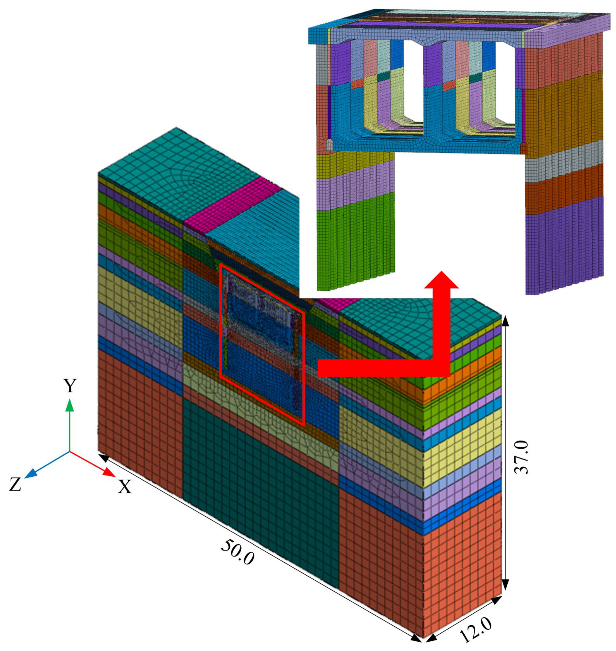
5.1. Numerical Model

In order to investigate the internal force and deformation of the PPWS in different construction stages and the role of joints in the PPWS, this paper adopts the finite element software Midas GTS NX [32] to establish a three-dimensional numerical model to analyze the construction mechanical effect of the PPWS.
The tunnel was constructed using the open-cut method with an overburden thickness of 4.0 m and a total width of 9.9 m. Considering the influence of the boundary effects of the computational model and the computational efficiency, the five-ring liner was selected for modeling, as shown in Figure 10. The distance from the lateral boundary of the model and the distance between the lower bound of the model from the top should be taken sufficiently so that the effects of the boundaries in the numerical model on the results were minimized. The displacement and the stress contours in the finite element software indicate that this distance is sufficient [33]. The model size is 50.0 m (X-direction) × 37.0 m (Y-direction) × 12.0 m (Z-direction). A fixed boundary is used at the bottom. The rest of the boundary restricts its normal displacement.

5.2. The Constitutive Model of the Soil and Structure

Soil is simulated by the Modified Mohr–Coulomb model (MMC). Compared to the Mohr–Coulomb model, the MMC model consists of a nonlinear elastic and elastic–plastic model, with no effect between shear and compression yield. Therefore, the MMC corrects the abnormality of the pit bottom and surface uplift [34]. The support structures, such as precast piles, tunnel linings, and steel supports, are simulated with elastic. Steel supports are simulated with beam, shotcrete is simulated with shell, prestressed reinforcements are simulated with embedded truss, and the rest are solid.
The MMC employs a double-hardening model in the shear and compression directions. This model accounts for the impact of unloading excavation, and results in more accurate simulations. The elastic modulus of the soil can be adjusted to different values according to loading and unloading to restore its loading and unloading properties. The main parameters of the MMC are secant elastic modulus ( E 50 r e f ), tangent elastic modulus ( E o e d r e f ), and unloading elastic modulus ( E u r r e f ).
For natural state soils, the stress–strain behavior during a single loading is highly nonlinear, with different moduli depending on the stress level. Thus E 50 identifies the stress-related modulus of a single loading, replacing the initial modulus E as the tangent modulus for small strains. E 50 is shown in Equation (1):
E 50 = E 50 r e f σ 3 + c cot φ p σ r e f + c cot φ p m
where c is the internal friction angle; m is the power exponent associated with the stress level; φ is the cohesion under p-stress conditions; and E 50 r e f corresponds to the reference stress σ r e f . The actual modulus depends on the effective confirming pressure σ 3 in the triaxial test. The σ r e f is expressed in terms of a certain σ 3 . Associate the equations corresponding to different σ 3 to arrive at E 50 r e f .
The modified Mohr–Coulomb model highlights two main types of hardening: shear hardening, and compression hardening. Shear hardening is used to simulate the partial load phenomenon during the loading and unloading processes. The unloaded and reloaded stress paths are represented by another stress-related modulus E u r , which is given by Equation (2):
E u r = E u r r e f σ 3 + c cot φ p σ r e f + c cot φ p m
where E u r r e f is the reference modulus for unloading and reloading. E u r is the actual modulus of elasticity, which can be obtained from Hooke’s law of conversion of modulus of elasticity to shear modulus in Equation (3):
E u r = 2 1 + μ u r G u r
where G u r is the shear modulus.
Compression hardening is used to simulate is used to simulate the phenomenon of plastic strain due to initial compression during consolidation. The relationship between E 50 and E o e d is shown in Equation (4):
E o e d = E o e d r e f σ 3 + c cot φ p σ r e f + c cot φ p m
According to the geological investigation report, the physical and mechanical parameters of the strata are obtained as shown in Table 2. The physical and mechanical parameters of the structure are shown in Table 3.
The general contact is employed to simulate the interactions between the components, with normal direction contact facilitating compressive stress transfer, and the tangential direction governed by the Coulomb friction model. The friction coefficient between components of the main lining structure is set at 0.2, while for other components, it is 0.6 [19,21,35].

5.3. Mesh Sensitivity Analyses

The mesh sensitivity of the model was analyzed in order to determine the final mesh size of the model. The meshing was carried out by dividing the stratum into inner and outer layers, and the inner layer was taken to be 2.5 times the width of the pit, with a width of 2.5 m and a depth of 18.7 m. The rest is the outer layer stratum. The three model element sizes are shown in Table 4. Figure 11 shows the calculation results of the three models. From the results, it can be seen that there is not much difference among the three results. Therefore, the result of Model1 was used for analysis. Model1 has a total of 568,350 elements and 348,005 nodes.

5.4. Model Validation

Figure 12 shows a comparison of the results between the monitoring and numerical simulation, which demonstrates the excellent agreement and validates the structural modeling scheme and material parameters used in this paper.

5.5. Numerical Results and Analysis

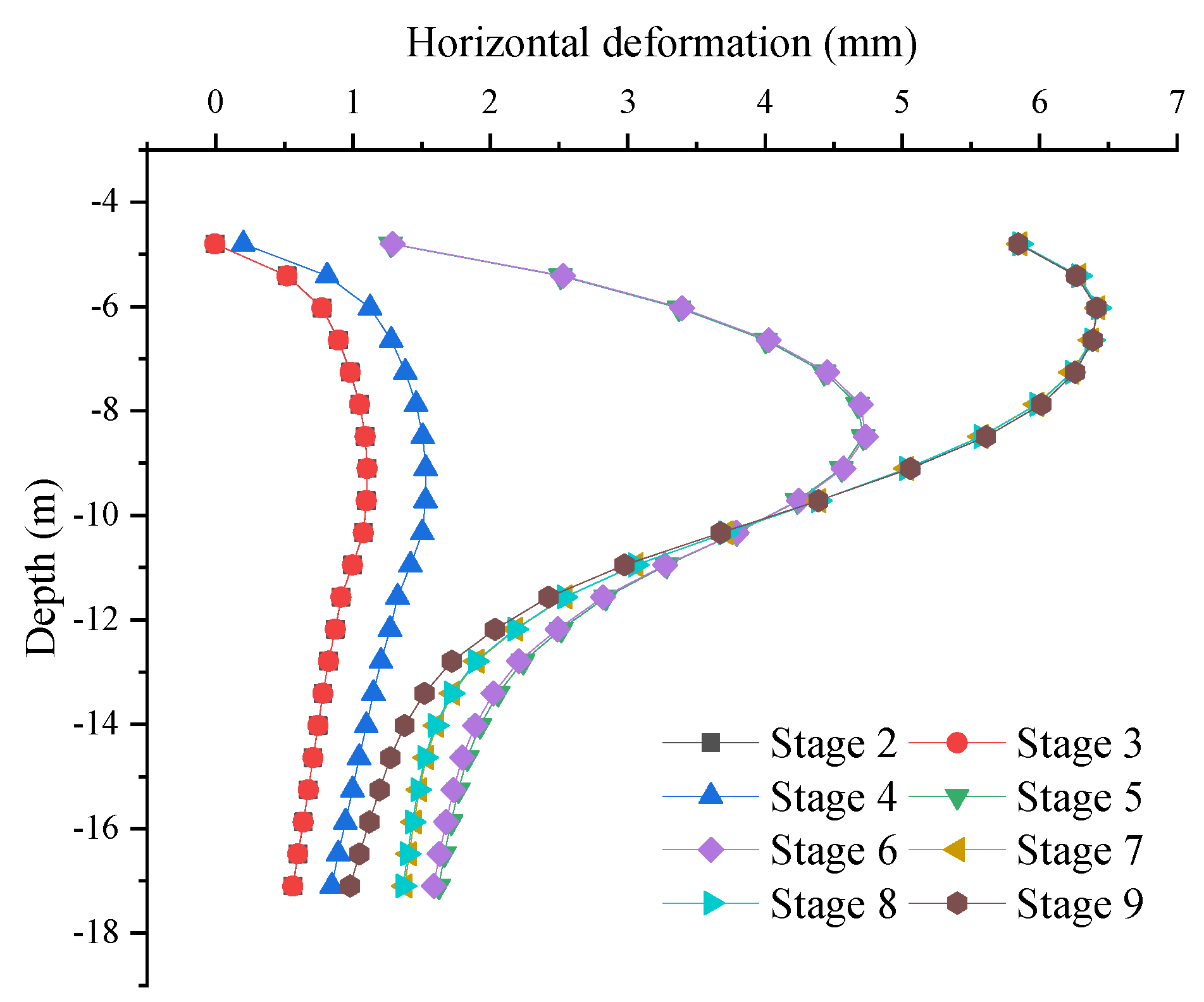
5.5.1. Deformation of The Precast Piles

Figure 13 shows the relationship between the horizontal deformation and depth of precast piles at different stages of construction. Excavation unloading caused the precast piles to deform towards the excavation side, with horizontal deformation gradually increasing as construction advanced. The maximum deformation of the precast piles, reaching 4.73 mm, occurred at the middle of the pile when the pit was excavated to its bottom. The horizontal deformation at the pile top increased when the steel support was removed, and its maximum deformation increased to 6.42 mm. After the steel support was removed, the horizontal deformation stabilized. The steel supports effectively constrained horizontal deformation of the precast piles until their removal. After the prefabricated piles and the sidewall formed an effective connection through the joints, the horizontal displacement at the pile top was effectively controlled and no longer increased, while the horizontal displacement at the pile toe was reduced to 0.98 mm, a decrease of 0.39 mm. This indicates that the lining formed a composite structure with the precast piles after the joints’ backfill, which was crucial for connection.

5.5.2. Stress of The Precast Piles

Figure 14 shows the minimum principal stress cloud for precast piles under each critical construction stage. The minimum principal stresses of precast piles exhibit a non-uniform distribution along the buried depth. The minimum principal stress at the bottom of the precast pile was relatively large before pit excavation, and gradually increased as pit excavation proceeded. The minimum principal stress of the precast piles was most significantly affected when the pit was excavated to the bottom of the pit, and the minimum principal stress extreme value increased from −0.46 MPa to −5.30 MPa. Due to excavation, the minimum principal stress was larger on the facing soil side in the middle of the pile. Dividing the pile at its middle, the minimum principal stress on the facing soil side of the pile is relatively large above the middle of the pile, and the opposite is true below the middle of the pile.

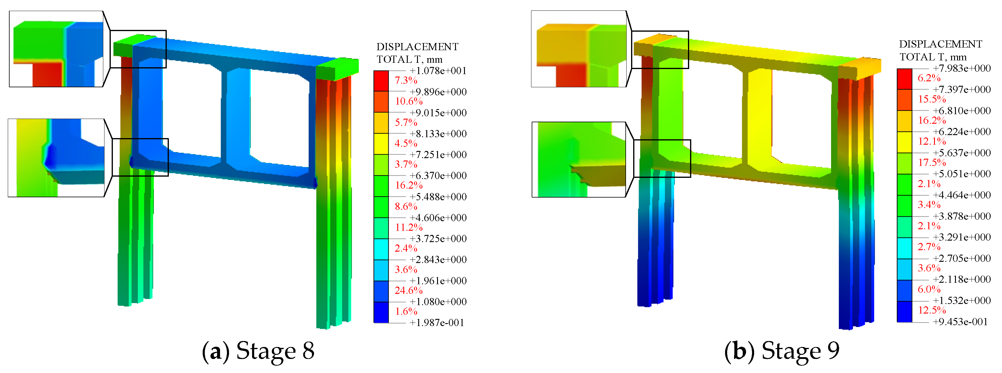
5.5.3. Deformation of The Precast Piles

Figure 15 shows the deformation cloud of the composite structure under each construction stage after the backfilling of joints and the assembly gap. The deformation of precast piles and lining differed greatly. The deformation at the joints was uniform. Therefore, the joints were able to transfer the deformation effectively, allowing the precast piles and lining to deform together. Displacement for both sides of the joints is shown in Table 5. The displacement at the connection of joint B to the pile was reduced by 0.96 mm compared to the disconnection. In contrast, the displacement distribution at joint A was consistent, and showed no significant difference due to the continuous connection with the crown beam. Table 6 shows the deformation at various locations on the sidewall and pile top. After the cover backfill, the displacement of the precast pile top decreased by 2.93 mm, while the displacements at the top plate, baseplate, and sidewall increased by 4.38 mm, 4.29 mm, and 3.82 mm, respectively. Therefore, the liner and precast piles were connected by joints to form the PPWS to withstand the external loads. The lining also supported the precast piles.

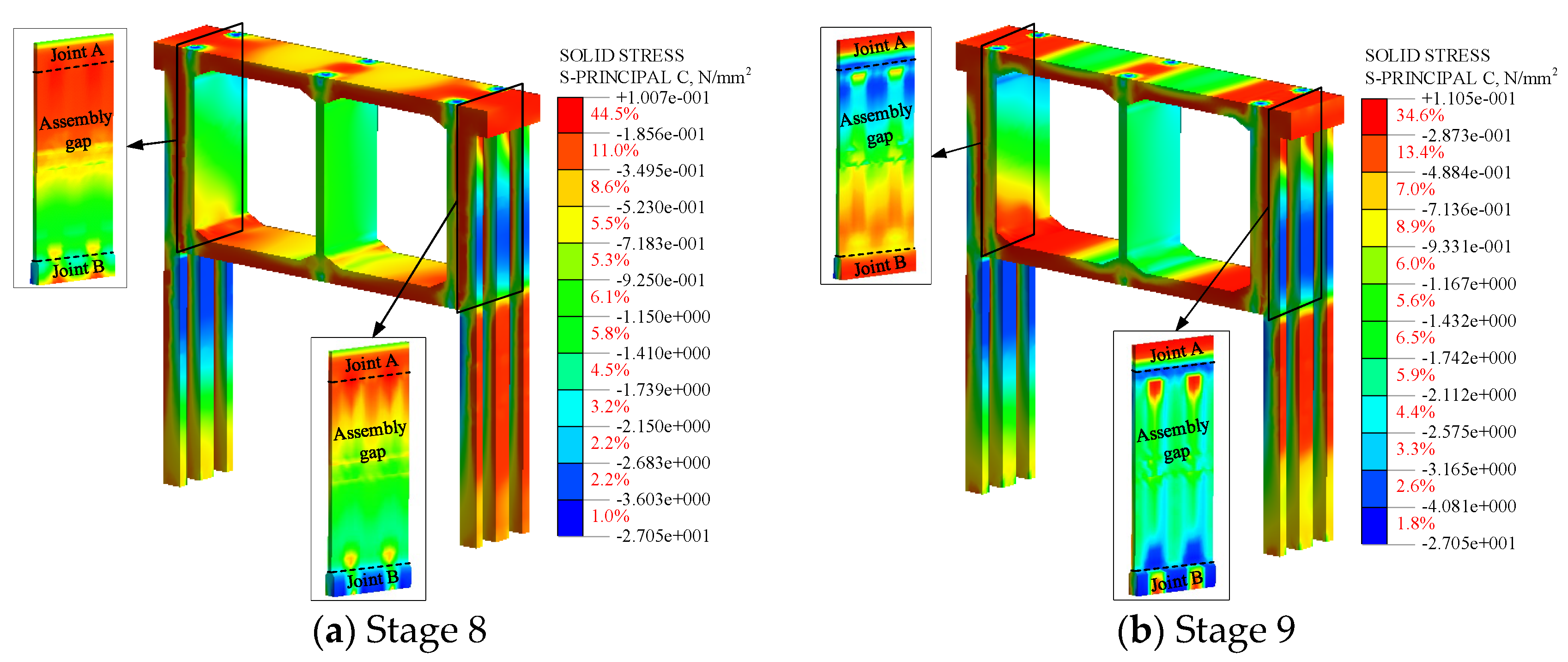
5.5.4. Stress and Strain of The PPWS

Figure 16 shows the minimum principal stress cloud for the PPWS. The lining was subject to stress concentrations in the presence of prestressing tendons. The minimum principal stresses maximum for sidewalls and precast piles are shown in Table 7. After the joints were backfilled, the precast piles predominantly carried external loads, with minimum principal stresses at the precast piles exceeding those at the tunnel sidewalls by 4.26 MPa and 5.49 MPa, respectively. The minimum principal stresses were greater at the connection to the pile than at the unconnected area. Therefore, the joints and assembly gaps effectively acted as force transfer hubs in the PPWS. The stress distribution at joint A is more uniform because there is no disconnection between joint A and the crown beam. Joint B also shows a non-uniform distribution with higher stresses at the connection.
Figure 17 shows the minimum principal strain cloud of the PPWS, and the strain distribution of PPWS is similar to the stress distribution. However, the strain distribution at the precast piles is relatively uniform and larger than at the lining. This is consistent with the large deformation of the precast piles, and also indicates that the PPWS fully utilizes the retaining effect of the precast piles.

5.5.5. Internal Forces of The PPWS

Figure 18 shows the distribution of internal forces in the lining (green wireframe shows the lining schematic). After the overburden backfill, there was a significant increase in the internal forces in the lining structure, with relatively high internal forces in the shoulder of the lining, and high shear and bending moments in the middle of the base plate. Consequently, the joint A connections and the middle of the base plate are the weak points of the structure, which need to be paid more attention to during the construction and operation stages. Although the joints effectively connect the sidewall and the precast piles, there is still a lack of connection at the assembly gaps. Therefore, the internal forces of the lining adopted cast-in-place composite sidewall is lower than the PPWS after the overburden backfill.

6. Conclusions and Recommendations

The following conclusions have been obtained from the research in this paper:
  • The open-cut section tunnel constructed with PPWS increases the prefabrication rate and utilized retaining piles. The pile and tunnel lining are constructed using fully precast technology in the PPWS. After the tunnel lining is assembled, the precast piles are connected to the sidewall through wet joints.
  • The development of earth pressure on the PPWS can be divided into three stages: pit excavation (Stages I), lining construction (Stage II), and PPWS formation (Stage III). After the connection of the precast piles to the lining, the earth pressure on the tunnel sidewall connection was reduced, so the PPWS effectively utilized the retaining effect of the precast piles.
  • The stresses and deformations of PPWS differ on both sides of the joints and transition uniformly at the joints. Therefore, the joints which act as the force-transmitting hub effectively connect the precast piles and the tunnel lining.
  • The horizontal deformation of the precast piles was reduced as a result of the formation of the composite structure. Therefore, the precast piles should be connected to the tunnel lining as soon as possible after the pit excavation is completed.
  • The liner shoulder and the middle of the base plate experienced high internal forces following the overburdened backfill. Consequently, the middle of the base plate and the joints is a weak point of the PPWS, which should be emphasized during construction and operation.
Overall, the PPWS is a green construction technique which improves the prefabrication rate of the open-cut section tunnel and avoids waste of retaining piles. However, PPWS still has some disadvantages: assembly gap width, joint selection, and segmentation can be optimized. The optimization of this scheme will be continued in the future to promote the application of this type of structure.

Author Contributions

S.M. and Z.L.: conceptualization, methodology, project administration, and writing the original draft; R.F.: data collection, plotting curves and analysis, and review. All authors have read and agreed to the published version of the manuscript.

Funding

This research was funded by the National Key Research and Development Program of China (No. 2018YFC0808705), and the Science and Technology Research and Development Program of China Railway Siyuan Survey and Design Group Co., Ltd. (No. 2021K026).

Data Availability Statement

The data used to support the findings of this study are available from the corresponding author upon request.

Acknowledgments

Financial supports are gratefully acknowledged.

Conflicts of Interest

Author Ruian Fu was employed by the company China Railway Siyuan Survey and Design Group Co., Ltd. The remaining authors declare that the research was conducted in the absence of any commercial or financial relationships that could be construed as a potential conflict of interest.

References

  1. Koyama, Y. Present status and technology of shield tunneling method in Japan. Tunn. Undergr. Space Technol. 2003, 18, 145–159. [Google Scholar] [CrossRef]
  2. Li, P.; Wei, Y.; Zhang, M.; Huang, Q.; Wang, F. Influence of non-associated flow rule on passive face instability for shallow shield tunnels. Tunn. Undergr. Space Technol. 2022, 119, 104202. [Google Scholar] [CrossRef]
  3. Yang, X. Development and prospect of construction technology for prefabricated metro station in China. Tunn. Constr. 2021, 41, 1849–1870. [Google Scholar] [CrossRef]
  4. Yang, X. Research and application of prefabricated structure construction technology for metro station. Tunn. Constr. 2022, 42, 345–354. [Google Scholar] [CrossRef]
  5. Yang, X.; Lin, F. Prefabrication technology for underground metro station structure. Tunn. Undergr. Space Technol. 2021, 108, 103717. [Google Scholar] [CrossRef]
  6. Liu, T.; Lu, J.; Wang, D.; Liu, H.; Mo, N.; Zhai, L. 3D nonlinear finite element modelling of mechanical behavior of a new wall-beam-strut joint for prefabricated underground construction and validation again experimental testing. Structures 2021, 33, 3202–3221. [Google Scholar] [CrossRef]
  7. Li, Z.; Wang, C.; Su, H.; Shi, S. An experiment Study on the evolution law of concrete structure crack and joint seam deformation for tenon groove joints in the prefabricated metro station. China Civ. Eng. J. 2015, 48, 409–413. [Google Scholar]
  8. Li, Z.; Su, H.; Lu, S.; Wang, C.; Xu, X. Experimental study on flexural mechanical properties of the double tenon groove joints of prefabricated subway station. China Civ. Eng. J. 2017, 50, 28–32. [Google Scholar] [CrossRef]
  9. Ding, P.; Tao, L.; Yang, X.; Zhao, J.; Shi, C. Three-dimensional dynamic response analysis of a single-ring structure in a prefabricated subway station. Sustain. Cities Soc. 2019, 45, 271–286. [Google Scholar] [CrossRef]
  10. Tao, L.; Ding, P.; Shi, C.; Wu, X.; Wu, S.; Li, S. Shaking table test on seismic response characteristics of prefabricated subway station structure. Tunn. Undergr. Space Technol. 2019, 91, 102994. [Google Scholar] [CrossRef]
  11. Yang, X.; Lin, F.; Huang, M.; Cao, R. Experimental Analysis of Bending Stiffness Characteristics of Grouted Double Mortise-Tenon Joint for Prefabricated Metro Station Structure. Adv. Civ. Eng. 2021, 2021, 9958436. [Google Scholar] [CrossRef]
  12. Yang, X.; Lin, F.; Huang, M.; Valvo, P.S. Analysis of the Law of Joint Deformation for Grouted Mortise-Tenon Joint. Adv. Civ. Eng. 2022, 2022, 2909993. [Google Scholar] [CrossRef]
  13. Lin, F.; Yang, X. Mechanical properties analysis of joints for prefabricated metro station structure based on Whole-process in-situ monitoring. Tunn. Undergr. Space Technol. 2023, 138, 105202. [Google Scholar] [CrossRef]
  14. Tao, L.; Ding, P.; Yang, X.; Lin, P.; Shi, C.; Bao, Y.; Wei, P.; Zhao, J. Comparative study of the seismic performance of prefabricated and cast-in-place subway station structures by shaking table test. Tunn. Undergr. Space Technol. 2020, 105, 103583. [Google Scholar] [CrossRef]
  15. Tao, L.; Shi, C.; Ding, P.; Yang, X.; Bao, Y.; Wang, Z. Shaking table test of the effect of an enclosure structure on the seismic performance of a prefabricated subway station. Tunn. Undergr. Space Technol. 2022, 125, 104533. [Google Scholar] [CrossRef]
  16. Liu, H.; Han, Q.; Bai, Y.; Xu, C.; Du, X. Connection performance of restrained deformed grouted sleeve splice. Adv. Struct. Eng. 2018, 21, 488–499. [Google Scholar] [CrossRef]
  17. Liu, H.; Xu, C.; Du, X. Seismic response analysis of assembled monolithic subway station in the transverse direction. Eng. Struct. 2020, 219, 110970. [Google Scholar] [CrossRef]
  18. Chen, J.; Xu, C.; El Naggar, H.M.; Du, X. Study on seismic performance and index limits quantification for prefabricated subway station structures. Soil Dyn. Earthq. Eng. 2022, 162, 107460. [Google Scholar] [CrossRef]
  19. Chen, J.; Xu, C.; Du, X.; Han, R.; El Naggar, H.M. Physical and numerical modeling of seismic soil-structure interaction of prefabricated subway station structure. Eng. Struct. 2023, 290, 116364. [Google Scholar] [CrossRef]
  20. Chen, J.; Xu, C.; El Naggar, H.M.; Du, X. Comparative study on seismic performance of prefabricated and cast-in-place underground structures under different site conditions. Soil Dyn. Earthq. Eng. 2023, 171, 107998. [Google Scholar] [CrossRef]
  21. Chen, J.; Xu, C.; El Naggar, H.M.; Du, X. Seismic response analysis of rectangular prefabricated subway station structure. Tunn. Undergr. Space Technol. 2023, 131, 104795. [Google Scholar] [CrossRef]
  22. Fu, J.; Zhuang, H.; Wang, X.; Chen, S.; Chen, G. Influence of diaphragm wall connection mode on earthquake response of subway station structure. J. Nat. Disasters 2018, 27, 42–50. [Google Scholar] [CrossRef]
  23. Zhu, Z.; Guo, Z.; Lu, H. Shear performance of steel plug-in joints for the precast concrete sidewalls of subway entrance/exit structures. Case Stud. Constr. Mat. 2022, 17, e01313. [Google Scholar] [CrossRef]
  24. Qiu, T.; Sun, X.; Chen, X.; Su, D.; Zhang, J.; Xu, Z.; Song, R.; Wang, X. Experimental study and resilience modeling for prefabricated hollow diaphragm walls of full-assembled underground stations under urban multi-disturbance conditions. Tunn. Undergr. Space Technol. 2023, 135, 105044. [Google Scholar] [CrossRef]
  25. Lu, L.; Wang, G.; Wang, W.; Xu, Q.; Wang, Y. Research on the Structure Design and Mechanics Analysis of the Precast Pile-retaining Wall for Metro Station. J. Railw. Eng. Soc. 2017, 34, 93–98. [Google Scholar]
  26. Lu, L.; Wang, G.; Xu, Q.; Sun, H.; Wang, Y.; Wang, D. Deformation Behavior of the Support Structure of Deep Foundation Pit Supported by Composite Column Pile. J. Railw. Eng. Soc. 2019, 36, 93–98. [Google Scholar]
  27. Huang, Z.; Bai, H.; Zhang, C.; Ma, S.; Zhang, J. Mechanical Behavior and Damage Evolution of a Fabricated Rectangular Tunnel with a Mortise-and-Tenon Joint under Internal Explosion. J. Perform. Constr. Facil. 2023, 37. [Google Scholar] [CrossRef]
  28. Tang, B.; Cheng, S.; Yeboah, M.; Cheng, H.; Tang, Y.; Wang, C. Strength of fabricated enclosed roadway support structure for TBM-excavated coal mine roadways: Experimental and numerical study. Tunn. Undergr. Space Technol. 2023, 131, 104779. [Google Scholar] [CrossRef]
  29. Wei, K.; Xu, Y.; Li, M. Study on seismic performance of transverse frame of prefabricated elevated subway station. Structures 2022, 42, 255–267. [Google Scholar] [CrossRef]
  30. Xu, P.; Wei, Y.; Yang, Y.; Zhou, X. Application of fabricated corrugated steel plate in subway tunnel supporting structure. Case Stud. Constr. Mat. 2022, 17, e01323. [Google Scholar] [CrossRef]
  31. Wang, Q.; Qin, Q.; Jiang, B.; Xu, S.; Zeng, Z.; Luan, Y.; Liu, B.; Zhang, H. Mechanized construction of fabricated arches for large-diameter tunnels. Autom. Constr. 2021, 124, 103583. [Google Scholar] [CrossRef]
  32. Wang, H.; Tu, B.; Su, P.; Gu, X. MIDAS GTS NX Numerical Simulation Technology and Engineering Applications; Dalian University of Technology Press: Dalian, China, 2019; ISBN 9787568522465. [Google Scholar]
  33. Maleki, M.; Khezri, A.; Nosrati, M.; Hosseini, S.M.M.M. Seismic amplification factor and dynamic response of soil-nailed walls. Model. Earth Syst. Environ. 2022, 9, 1181–1198. [Google Scholar] [CrossRef]
  34. Huang, M.; Shen, Q.; Zhang, C.; Meng, Z. Study on the Influence of Construction Undercrossing Existing Station at Zero Distance in Confined Water. Appl. Sci. 2022, 12, 5887. [Google Scholar] [CrossRef]
  35. He, H.; Li, Z.; Ma, S.; Cui, X. Effect of strata restraint on seismic performance of prefabricated sidewall joints in fabricated subway stations. Front. Struct. Civ. Eng. 2023, 17, 763–779. [Google Scholar] [CrossRef]
Figure 1. The site of the test section.
Buildings 14 01693 g001
Figure 2. The cross-section of the tunnel constructed using PPWS (units: mm).
Buildings 14 01693 g002
Figure 3. PPWS: (a) integral structure; (b) structure partition; (c) reinforcement (units: mm).
Buildings 14 01693 g003
Figure 4. Connection method between precast pile and side wall: (a) cross-section; (b) top connection: joint A; (c) plan of joint A; (d) bottom connection: joint B.
Buildings 14 01693 g004
Figure 5. The assembly process of prefabricated structure.
Buildings 14 01693 g005aBuildings 14 01693 g005bBuildings 14 01693 g005c
Figure 6. Layout and installation of measurement points (units: mm). (a) Cross-section diagram of measurement points layout; (b) Layout of lining measurement points; (c) Layout of measurement points on the soil-facing side of prefabricated piles; (d) Layout of measurement points on the back soil side of prefabricated piles; (e) Installation of sidewall measurement points; (f) Installation of measurement points on the soil-facing side of prefabricated piles; (g) Installation of measurement points on the back soil side of prefabricated piles.
Buildings 14 01693 g006aBuildings 14 01693 g006b
Figure 8. Earth pressure on the back soil side of the prefabricated pile; (a) Earth pressure under different construction stages; (b) Earth pressure during construction.
Buildings 14 01693 g008
Figure 9. Earth pressure on the outside of the sidewall; (a) Earth pressure under different construction stages; (b) Earth pressure during construction.
Buildings 14 01693 g009aBuildings 14 01693 g009b
Figure 10. Numerical simulation model (units: m).
Buildings 14 01693 g010
Figure 11. Comparison of the horizontal deformation of the pile.
Buildings 14 01693 g011
Figure 12. Comparison of the pressure between the monitoring and numerical simulation.
Buildings 14 01693 g012
Figure 13. Horizontal deformation of precast piles under different construction stages.
Buildings 14 01693 g013
Figure 14. Minimum principal stress cloud for precast piles under critical construction stages.
Buildings 14 01693 g014
Figure 15. Deformation clouds of the PPWS at each construction stages.
Buildings 14 01693 g015
Figure 16. Minimum principal stress cloud for the PWWS at each construction stages.
Buildings 14 01693 g016
Figure 17. Minimum principal strain cloud for the PWWS at each construction stages.
Buildings 14 01693 g017
Figure 18. Internal forces in tunnel lining.
Buildings 14 01693 g018
Table 1. Comparison of earth pressure on the facing and back soil side of precast piles.
Measurement PointEarth Pressure (kPa)Difference (kPa)
ZY119.94−6.85
ZB113.09
ZY22.74−1.56
ZB31.18
ZY36.1324.32
ZB530.45
Table 2. Physical and mechanical parameters of the strata.
Soil LayerDepth (m)Density (kg/m3)Cohesion/c (kPa)Friction Angle/φ(°) E 50 r e f (MPa) E o e d r e f (MPa) E u r r e f (MPa)
Fill0–0.4190010105.95.947.2
Clay0.4–1.2184019.111.423.523.5188
Silt1.2–2.4184020.9202121168
Clay2.4–4.0184019.111.423.523.5188
Silt4.0–6.05184020.9202121168
Clay6.05–9.5178016.79.32222176
Silt9.5–10.7185020.621.721.521.5172
Silty clay10.7–12.3194020.314.82525200
Silty clay12.3–17.1198023.215.82727216
Silty fine sand17.1–18.720000202323184
Silty clay18.7–21.6202030.418.23030270
Silt21.6–23.4199022.221.52626208
Clay23.4–37.0196038.317.930.430.4243.2
Table 3. Physical and mechanical parameters of the structure.
StructureDensity (kg/m3)Elastic Modulus/E (GPa)Poisson Ratio
Lining250034.50.2
Crown Beam250034.50.2
Precast Pile250034.50.2
Joint250034.50.2
Assembly Gap230025.50.2
Cushion230025.50.2
Steel Support78502100.3
Table 4. Grid size of the model.
ModelPPWSInner StratumOuter Stratum
Model1150 mm150–600 mm600–1200 mm
Model2300 mm300–800 mm800–1600 mm
Model3450 mm450–900 mm900–1800 mm
Table 5. Displacement for both sides of the joints.
Displacement at Precast Pile (mm)Displacement at Sidewall (mm)
ConnectionUnconnected Part
Joint A6.81-5.32
Joint B4.245.25.99
Table 6. Deformation at different construction stage.
Displacement (mm)Difference (mm)
Construction StageStage 8Stage 9
Top Plate1.846.224.38
Baseplate3.137.424.29
Sidewall1.415.233.82
Precast Pile Tip10.597.66−2.93
Table 7. Maximum minimum principal stress for sidewall and precast piles.
Maximum Minimum Principal Stress (MPa)
Construction StageStage 8Stage 9
Precast Pile−8.55−9.41
Sidewall−3.06−5.15
Difference5.494.26
Disclaimer/Publisher’s Note: The statements, opinions and data contained in all publications are solely those of the individual author(s) and contributor(s) and not of MDPI and/or the editor(s). MDPI and/or the editor(s) disclaim responsibility for any injury to people or property resulting from any ideas, methods, instructions or products referred to in the content.

