Article

Selection and Layout Optimization of Double Tower Cranes

1
School of Management Science and Real Estate, Chongqing University, Chongqing 400045, China
2
CCCC Urban Investment Holding Co., Ltd., Guangzhou 510000, China
3
China Construction Second Engineering Bureau Ltd., Beijing 100160, China
4
Chongqing Jianzhu College, Chongqing 400072, China
*
Author to whom correspondence should be addressed.
Buildings 2024, 14(6), 1705; https://doi.org/10.3390/buildings14061705
Submission received: 10 May 2024 / Revised: 1 June 2024 / Accepted: 3 June 2024 / Published: 7 June 2024
(This article belongs to the Section Construction Management, and Computers & Digitization)

Abstract

:
As the scale of construction expanded and the number of prefabricated buildings increased, a single tower crane could no longer meet the construction requirements, necessitating the simultaneous operation of more tower cranes to improve construction efficiency. To optimize the efficiency and cost of lifting prefabricated concrete components and address the selection and layout optimization of dual tower cranes, this paper proposed a double tower crane selection and positioning optimization model that integrated feasible layout area solving and optimization based on different objectives. By analyzing the mathematical relationship between the layout positions of the tower cranes and the positions of the prefabricated component storage yard and installation sites, a mathematical model for the feasible layout area of double tower cranes was established and solved using a genetic algorithm. On this basis, optimization models were established with the objectives of minimizing cost, achieving the shortest total lifting time, and achieving the maximum value coefficient, and they were solved using a genetic algorithm. The model was verified and analyzed through a case study. The research results indicated that the double tower crane selection scheme could achieve more than twice the lifting efficiency of the same model single tower crane. When the total lifting time was similar, choosing based on the principles of value engineering could yield the optimal solution with lower costs. These research findings provided a reference for the selection of tower crane schemes and the cost reduction and efficiency improvement of on-site prefabricated concrete component lifting construction.

1. Introduction

Prefabricated construction, which utilizes factory-made components, modular design, and on-site assembly, is a construction method that offers numerous advantages compared to traditional construction methods, including fast construction speed, quality control, resource conservation, and pollution reduction. Consequently, many countries and regions have enacted policies to encourage and support the development of prefabricated construction [1]. The production of the main components in prefabricated construction is typically completed in factories, and they are then transported to the site for installation. The lifting of prefabricated components is a critical process throughout the construction process of prefabricated buildings. Prefabricated buildings often require a large number of prefabricated components and modules for on-site assembly, and the lifting of these components and modules typically requires large lifting equipment. Tower cranes, as a type of lifting equipment, possess advantages such as tall lifting height, high lifting capacity, and operational flexibility. These attributes enable them to efficiently undertake various lifting tasks, making them essential equipment in prefabricated construction sites [2]. The selection of tower cranes and tower crane layout planning (TCLP) can have a significant impact on costs and construction schedules. Multi-tower crane layout planning (MTCLP), which involves the selection of tower crane types, quantities, and positions, as well as material storage locations, is crucial for balancing material transportation efficiency and overall costs. However, determining the optimal layout scheme with appropriate tower cranes and tower crane positions remains a significant challenge: many construction managers primarily rely on their own experience to make decisions regarding tower crane type selection, quantity, and on-site layout, lacking quantitative analysis of factors such as site conditions, prefabricated component quality, tower crane performance, and operating costs [3]. Currently, scholars are applying mathematical methods to determine the optimal positions of tower cranes. These methods systematically consider different site conditions and constraints to address the challenges of TCLP, further assisting the empirical decision-making process.
In previous studies, researchers have commonly considered minimizing the shortest lifting time or the overall cost as the primary objectives in tower crane layout planning. They constructed mathematical models to find optimal or approximate optimal solutions under a series of constraints. Early research laid the foundation for determining tower crane positions. As research progressed, the construction of models became more comprehensive, considering additional constraints and optimization objectives. To solve the problem, scholars have employed various optimization methods, ranging from exact solution methods such as branch and bound [4] to metaheuristic algorithms such as genetic algorithms [5], particle swarm optimization [6], etc., to address tower crane layout optimization problems. Additionally, some studies have utilized hybrid metaheuristic algorithms, combining multiple heuristic strategies to more effectively solve specific problems [7]. These algorithms can effectively improve the speed of finding suboptimal solutions. However, with the increasing scale of prefabricated construction and the acceleration of construction progress, situations often arise where a single tower crane cannot meet the construction needs. It becomes necessary to increase the number of tower cranes to complete the lifting work, and factors such as the prefabricated component yard, quality, and installation positions all influence the selection and layout of tower cranes. Therefore, how to optimize the selection and positioning of two tower cranes working simultaneously at the construction site is an urgent problem that needs to be addressed.
Despite some research progress, existing studies still have certain limitations. For instance, there is relatively limited research in the field of double tower crane layout planning, and there is a lack of in-depth optimization studies specifically tailored to prefabricated construction. Therefore, this paper aims to establish a mathematical model for double tower crane layout planning based on the principles of value engineering, combined with the mathematical relationship between tower crane placement and prefabricated component yard positioning. Corresponding optimization algorithms were proposed. The effectiveness of the model was validated through case studies, and the potential applications in practical engineering were explored.

2. Literature Review

2.1. Selection and Layout Planning of Tower Cranes

Based on the different numbers of research objects, studies related to tower crane selection and positioning problems can be divided into research on single tower crane selection and positioning and research on multi-tower crane selection and positioning.
The layout problem of a single tower crane is the basis of research on tower crane layout optimization. Choi and Harris [8] were the first to conduct optimization research on the optimal placement positions of single tower cranes, with the optimization objective being the minimization of total costs. Building on the work of Choi and Harris, Nadoushani et al. [9] employed the idea of mixed integer programming and set the minimization of leasing costs as the optimization objective, constructing an optimization model and discussing the optimal tower crane model and position under this objective. Zhang et al. [10] established an optimization mathematical model based on minimizing the hook running time by studying the constraint relationships between supply points, demand points, and crane positions. Subsequently, to improve the optimization results of single tower crane operations, Huang et al. [11] considered the yard to be a variable and proposed a mixed integer linear model based on Zhang’s model, which determined not only the optimal tower crane positions but also the optimal yard positions. Building on previous research, Huang and Wong [12] constructed a mixed integer programming model for tower crane movement, achieving more accurate results compared to past studies. However, a limitation of their research is the lack of consideration of safety factors and other constraints related to tower crane operations.
As the volume and scale of construction projects continue to increase, a single crane often struggles to handle all lifting tasks. In such cases, multiple cranes need to be used simultaneously to meet construction deadlines, prompting researchers to focus on the optimization of crane groups. Mathematical models in tower crane layout planning studies are used to find optimal solutions or strategies under a set of defined constraints, with the aim of maximizing or minimizing specific objective functions. Zhang’s model [13] laid the foundation for determining the positions of tower crane groups. This model includes criteria such as balancing workload, minimizing path conflicts, and maximizing efficiency in time and cost. Many subsequent studies on tower crane layout planning have referenced this model and its assumptions, incorporating mixed integer programming (MIP), mixed integer linear programming (MILP), and binary mixed integer linear programming (BMILP) models to formulate tower crane layout planning problems with constraints and objectives, aiming to minimize transportation time or costs. Abubakr and Marzouk [14] further refined the optimization model based on Zhang’s research, resulting in a more accurate decision-making process for determining the number of cranes used in construction. Dienstknecht [14] developed an exact branch-and-bound approach that overcomes the limitations encountered when using CPLEX to handle mixed-integer programming. Briskorn [15] constrained the Tower Crane Selection and Placement Problem to a set of discrete candidate locations, simplifying it to a Weighted Set Cover Problem without losing optimality. As the number of cranes deployed in construction increases, scholars have found that the efficiency of work teams is also a key factor affecting lifting efficiency. Peng et al. [16] constructed an optimization model to explore the impact of the number of work teams on the time and cost of lifting using multiple cranes, using mobile cranes as the research object and basing the model on the shortest construction period and the lowest cost. Ji [17] optimized the positioning of multiple cranes and yards, considering the collaborative capabilities within the overlapping working ranges of cranes during the optimization process. As research progresses, the composition of constraints, influencing factors, and optimization objectives has become more comprehensive.

2.2. Optimization Problem

Studies related to tower crane layout planning typically aim to minimize hoisting time or transportation costs. Li [18] optimized for achieving the shortest hoisting time as the objective function, while Nadoushani [9], Briskorn [19], and others aimed to minimize total costs. Unlike many studies that aimed to minimize the operation time of individual tasks, Khodabandelu [20] developed an agent-based modeling simulation tool to investigate the impact of dynamic supply selection on crane efficiency. Ji [17] considered a combination of the above research objectives, aiming to study tower crane layout planning that minimizes overall time and costs. In addition, metrics such as minimizing path conflicts and ensuring safety are also common research objectives in tower crane layout planning.
Optimization algorithms are used to find the optimal or approximately optimal solutions within given mathematical model constraints to meet specific goals, such as cost minimization, maximizing efficiency, or optimizing workload distribution. The branch and bound method is a precise solving method that gradually converges to the optimal solution by continuously decomposing and searching, ensuring that the best tower crane layout planning solution is found. To shorten the computation time, metaheuristic algorithms are used to find approximately optimal tower crane layout solutions within a reasonable time. Marzouk [5] applied the genetic algorithm (GA) to determine tower crane layout, achieving the different objectives of minimizing conflicts and minimizing time and costs. Yang [6] used particle swarm optimization (PSO), while Wu [21] used simulated annealing (SA) to determine tower crane layout with the objective of minimizing overall costs. The firefly algorithm (FA) has also been used in related research. Compared to single metaheuristic algorithms, hybrid metaheuristic algorithms combine multiple heuristic strategies, leveraging the advantages of different algorithms more effectively, and they may be more efficient in solving specific problems. The particle bee algorithm (PBA), combining bees (bee algorithm, BA) and birds (particle swarm optimization, PSO), was introduced to minimize crane operating costs by determining tower crane positions [7].
Some auxiliary tools are used in tower crane layout planning. Building Information Modeling (BIM) can provide mathematical inputs for tower crane layout planning mathematical models and perform conflict detection on the resulting optimal tower crane layout plans. Riga [22] retrieved site conditions and building elements through BIM and approximated complex shapes using convex hulls. Dasovic [23] proposed an active Building Information Modeling (BIM) approach that integrates intelligent algorithms and automation tools, transforming BIM models from mere information storage and display platforms to dynamic optimization and decision support systems. A virtual reality (VR) tool developed by Zhang [24] can generate tower crane layouts through real-time feasibility checks, select layouts through multi-criteria performance evaluations, and simulate interactive tower crane lifting and lowering. Li [18] employed a generative adversarial network (GAN) called Crane GAN and proposed an automatic TCLP system that generates tower crane layouts based on blueprint inputs without manual information extraction.
Table 1 lists some previous studies, indicating whether they focused on single or multiple tower cranes, their research objectives, and the optimization algorithms used.
In summary, the studies by the aforementioned scholars lack the comprehensive exploration of feasible layout areas for twin tower cranes in construction. Specific mathematical models for feasible areas were not proposed, despite factors such as the prefabricated component yard, its quality, and installation positions all influencing the selection and layout of tower cranes. Studies on optimizing tower crane layouts in prefabricated construction are insufficiently focused, with optimization goals often centered around minimizing the hoisting time or cost rather than incorporating value engineering. Therefore, this paper establishes a mathematical model based on the relationship between the positions of tower crane placements and prefabricated component yards, as well as installation positions, with a foundation in value engineering for optimizing feasible layout areas for attached twin tower cranes in prefabricated construction. By utilizing genetic algorithms to solve for maximum value engineering coefficients, the model is validated through case studies.

3. Methodology

3.1. Problem Description and Assumptions

This study on the selection and layout optimization of double tower cranes involved two steps. Firstly, establishing a model for feasible area arrangement of double tower cranes to determine the applicable scenarios and identify feasible layout areas for the two tower cranes. Secondly, developing a value engineering-based model for the selection and layout optimization of double tower cranes, aiming to find the optimal positions for the two tower cranes within the feasible layout areas under different objective functions.
The known conditions and basic assumptions of this study were as follows:
  • Known Conditions
    • The coordinates of each vertex of the building outline are known;
    • The coordinates of the demand points and supply points for components are known;
    • The tower crane studied in this paper is a luffing jib tower crane, with the attachment path distance from the building outline denoted as dBTC, and dBTC = 4 m.
  • Assumptions
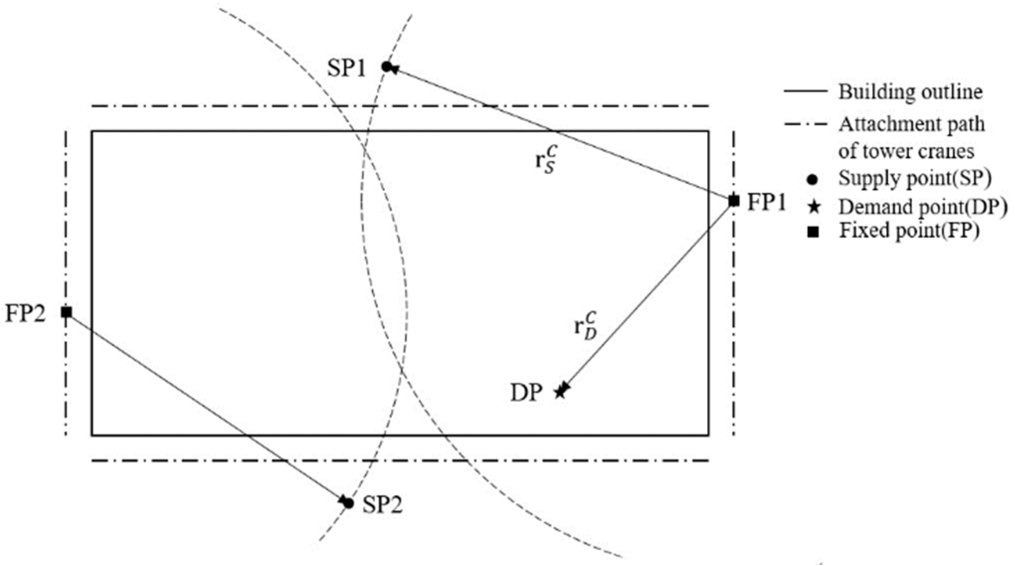
    • In the mathematical model, the stacking and unloading/installation points of prefabricated components are simplified as points, without considering their spatial volume effects, referred to as supply points (SPs) and demand points (DPs), respectively.
    • In the mathematical model, the base of the tower crane is simplified as a point, referred to as a fixed point (FP), without considering its spatial volume effects.
    • The impact of terrain, roads, and obstacles on this study is not considered.
    • Each lifting task is executed by only one tower crane, and both tower cranes perform lifting simultaneously. Task allocation is not considered.
    • The spatial lifting problem is considered on standard floor levels, without considering staggered construction.
The relationship between supply points (SPs), demand points (DPs) and fixed points (FPs) is illustrated in Figure 1.
In Figure 1, r D C represents the distance between the base of the tower crane and the demand point of the component, while r S C represents the distance between the base of the tower crane and the supply point of the component.

3.2. Variable Setting

The parameters to be used in the modeling process, along with their descriptions, are presented in Table 2.

3.3. Model of Feasible Layout Area for Double Tower Cranes

This model consists of two main parts: analysis of the applicability of double tower cranes and analysis of the layout area of double tower cranes.
  • Applicability of Double Tower Cranes
The lifting capacity of a crane was determined by the boom length–load curve. Taking the TC6013 tower crane as an example, the lifting capacities corresponding to different boom lengths and their fitting functions are shown in Figure 2.
In construction projects, when a given model of tower crane cannot fulfill all lifting tasks at any feasible layout point but adding another tower crane of the same model would enable the completion of all lifting tasks, a double tower crane configuration must be employed. The conditions to be met are as follows:
∃ tower crane fixed points x c 1 , y c 1 , x c 2 , y c 2
For the ∀ component supply point S x s i , y s i i I and the ∀ component demand point D x d j , y d j j J
x c 1 x s i 2 + y c 1 y s i 2 L Q ,   x c 1 x d j 2 + y c 1 y d j 2 L Q
or
x c 2 x s i 2 + y c 2 y s i 2 L Q ,   x c 2 x d j 2 + y c 2 y d j 2 L Q
II.
Layout Area of Double Tower Cranes
Continuing from the conditions outlined earlier for the use of double tower cranes, we proceeded with the analysis of feasible layout areas for double tower cranes.
As shown in Figure 3, there were a total of six component demand points on the work surface of this construction project, namely Di, Di+1, Di+2, Di+3, Di+4, and Di+5, where Di, Di+1, Di+3, and Di+4 require components with a weight of Q h , while Di+2 and Di+5 require prefabricated components with a weight of Q k , where Q h > Q k . There were two component supply points, namely Sj and Sj+1. The maximum jib radius of the tower crane corresponding to the two types of components was denoted as L Q h and L Q k . As shown in Figure 3, the area enclosed by six circles with centers at Di, Di+1, Di+2, Di+3, Di+4, and Di+5 and radii L Q h and L Q k , respectively, along with the building outline, formed the feasible layout area for the tower crane. Our analysis revealed that only when two tower cranes of this model were positioned in regions C and H could the lifting tasks for the six component demand points be completed.
The regions C and H were designated as Dtc, representing the feasible layout area for the double tower cranes. Region C was named dtcI, and region H was named dtcJ, representing the feasible layout areas for TC1 and TC2, respectively.
To use the double tower cranes for coordinated lifting operations, the safety distance between the adjacent tower crane towers, denoted as L T C , had to be considered. L T C was set to 2 m. Therefore, when the first tower crane selected a point C1 within dtcI, the placement point C2 for the second tower crane had to satisfy the safety distance requirement:
x c 1 x c 2 2 + y c 1 y c 2 2 R + 2
R represents the distance from the end of the jib of the tower crane to the tower body.
As shown in Figure 4, when any point in dtcI is chosen as the placement point for TC1, there are some areas in dtcJ that cannot be used as the placement point for TC2 due to the safety distance requirement.
III.
Model of Feasible Layout Area for Double Tower Cranes
Based on the analysis above, the occurrences and layout areas of double tower cranes could be determined. To improve and expedite the problem-solving process, a mathematical model and solution algorithm was constructed as follows:
i. Input construction project information, as detailed in Table A1.
ii. Input parameters of tower crane, as detailed in Table A2.
iii. Solve for the type of double tower crane and feasible layout areas. The steps are as follows and illustrated in the flowchart in Figure 5:
a. Determine the maximum jib radius for each type of tower crane based on the known prefabricated component information. For the given N types of tower crane models, evaluate each one to find the maximum jib radius L Q n corresponding to a prefabricated component of weight Q .
b. Determine if all lifting tasks can be completed using a single tower crane. Check if there exists an installation point within the permissible area for tower crane placement that satisfies formulas (1) to (2). If such a point exists, it indicates that a single tower crane of that type can complete all lifting tasks.
c. Determine if all lifting tasks can be completed using two tower cranes. Check if there exist two layout points within the permissible area for tower crane placement that satisfy the conditions for the applicability of double tower cranes. If such points exist, it indicates that two tower cranes of that type can complete all lifting tasks while also meeting the safety distance requirements.
d. Identify the feasible layout area range for the combination of double tower cranes. Find all layout points that meet the requirements and designate them as Dtc, representing the feasible layout area for the double tower crane combination.
e. Determine the set of feasible layout positions for the combination of double tower cranes. Select any point from Dtc as the layout point for TC1, and through reverse deduction, determine all feasible layout points for TC2 corresponding to the selected point for TC1.
Figure 5. An algorithm flow chart of the feasible layout area of double tower cranes.
Buildings 14 01705 g005

3.4. Model for Selection and Layout Optimization of Double Tower Cranes under Different Objectives

In this section, mathematical models for optimizing the selection and layout of double tower cranes were established with the objectives of minimizing the lifting time, minimizing the operation cost, and maximizing the value engineering coefficient.
I.
Optimizing for Minimum Lifting Time
Tower cranes serve as crucial horizontal and vertical transportation tools in prefabricated construction, significantly impacting construction progress. Scholars often choose the total time T t o t a l taken by tower cranes to complete all lifting tasks as a key evaluation metric in the optimization research performed on tower crane layouts.
The lifting motion of a tower crane involves horizontal rotation and trolley slewing in the horizontal direction, as well as lifting and lowering in the vertical direction. Therefore, the lifting time of a tower crane mainly consists of horizontal and vertical motion times. The calculation of the lifting motion time of a tower crane is as follows:
i. Horizontal Motion Time Formula
The operating time of a tower crane mainly consists of horizontal and vertical motion times. When the tower crane performs horizontal motion, it needs to rotate around the tower base position C x c , y c , z c , moving the hook from directly above the component storage area (supply point S x s , y s , z s ) to directly above the component installation position (demand point D x d , y d , z d ). This process includes both the rotation of the jib and the radial motion of the trolley, as shown in Figure 6.
Formulas (4) to (6), respectively, calculate the horizontal distances from the demand point to the tower crane, from the supply point to the tower crane, and from the demand point to the supply point,
r D C = x d x c 2 + y d y c 2
r S C = x s x c 2 + y s y c 2
r S D = x d x s 2 + y d y s 2
Formulas (7) to (8), respectively, calculate the time for trolley to complete radial movement T r and the time for the jib to complete horizontal rotation T ω ,
T ω = 2 × 1 v ω arccos r S C 2 + r D C 2 + r S D 2 × r D C × r S C 2 0 arccos θ π
T r = r D C r S C v r 1 + r D C r S C v r 2
In practical scenarios, the radial motion of the trolley and the rotation of the jib can occur simultaneously. So, we combined Formulas (7) and (8) to calculate the total time for horizontal motion. The parameter α indicates the coordination between the trolley motion and the jib rotation, with values ranging from 0 to 1, where 0 and 1 represent fully simultaneous and fully sequential motion, respectively. Hence, the total time for horizontal motion is given by Formula (9).
T h = α T r + max 1 α T r , T ω t
ii. Vertical Motion Time Formula
When the jib rotates to the specified position and the trolley is directly above the demand or supply point, the hook needs to be lowered by the trolley to complete the loading or unloading task. After unloading, it needs to ascend without load to the safety height h 0 and return to the supply point SP. Formulas (10) to (12), respectively, calculate the lifting time T u p , lowering time T d o w n , and total vertical motion time T V ,
T u p = z d z s + h 0 V v 1 + h 0 V v 2
T d o w n = h 0 V v 1 + z d z s + h 0 V v 2
T V = T u p + T d o w n
iii. Lifting Motion Time Formula
In actual construction, the horizontal and vertical movements of tower cranes can occur simultaneously or sequentially. Therefore, the parameter γ is designed to represent the coordination between the horizontal and vertical movements of the tower crane, with values ranging from 0 to 1. The extreme values of 0 and 1, respectively, represent complete simultaneous and complete sequential movements. Thus, the time for a single tower crane to complete all lifting tasks T C when positioned at point C x c , y c , z c is given by
T C = γ T V + max 1 γ T V , T h + T u n l o a d + T l o a d
Based on the calculation of the time for a single lifting task mentioned above, the objective function for minimizing the total lifting time of the project is constructed as follows:
min T t o t a l = min max T 1 , T 2
= min max i 1 = 1 I 1 j = 1 J T 1 x c 1 , y c 1 , i 2 = 1 I 2 j = 1 J T 2 x c 2 , y c 2
The logic of the solution algorithm for minimizing the hoisting time objective is as follows, using the process outlined in Figure 7a:
a. Input the information of the building structure, components, and tower crane.
b. Calculate the maximum jib radius L for lifting the prefabricated components.
c. Compute the feasible layout area Dtc for the double tower crane, using the logic shown in Figure 5.
d. From Dtc, derive the feasible layout area dtcI for tower crane TC1 and dtcJ for tower crane TC2, using the logic shown in Figure 5.
e. Choose a point from dtcI as the installation point Ci for TC1 and find all feasible layout areas dtcij for TC2 corresponding to Ci. Choose a point x c j , y c j from dtcij as the installation point Cj for TC2.
f. Calculate the shortest hoisting time for all placement points in dtcI as min min T t o t a l i j . If min min T t o t a l i j = T t o t a l a b , then the corresponding placement points Ca and Cb are the optimal installation point combinations for the tower crane model.
g. Compute the minimum completion hoisting time for each type of double tower crane combination to determine the optimal layout for each type of double tower crane combination.
h. Compare the hoisting times for completing the project with different combinations of double tower cranes, selecting the optimal model combination corresponding to the shortest hoisting time.
II.
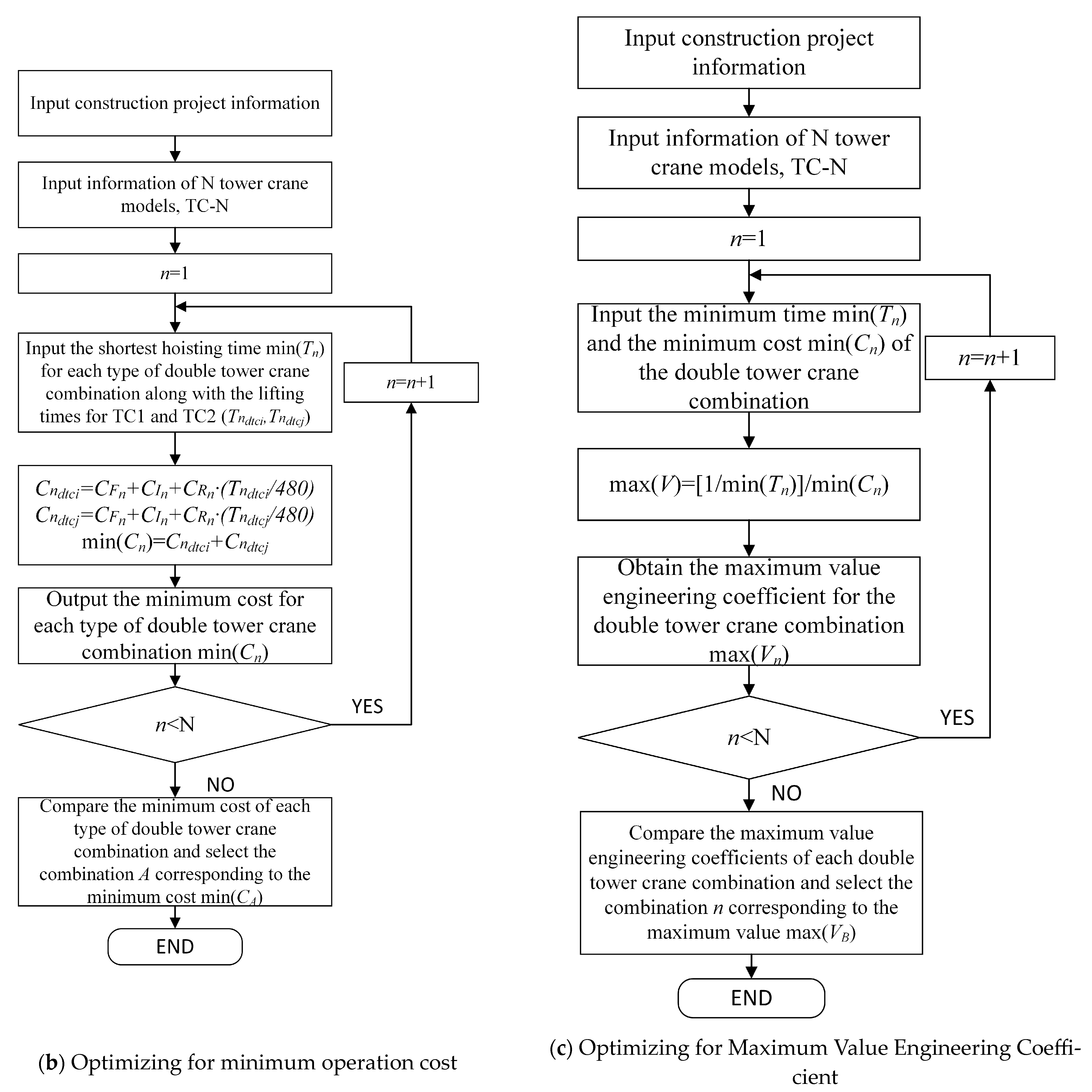
Optimizing for Minimum operation cost
As an essential economic indicator, operation cost has been regarded as a crucial criterion in recent research on tower crane layout optimization. Therefore, this paper considers it to be one of the optimization objectives for selection and layout. Assuming tower crane leasing as the premise, the operation cost of tower crane is divided into fixed cost and variable cost. The objective function is formulated as follows:
min C t o t a l = min C t c 1 + C t c 2
= min C F 1 + C I 1 + C R 1 × T n 480 + C F 2 + C I 2 + C R 2 × T n 480
To minimize operation cost as the objective, the algorithm logic is outlined as follows, using the process depicted in Figure 7b:
a. Input the coordinates of the building boundary lines, locations for prefabricated component stacking and installation, and parameters of prefabricated components;
b. Input the price information including leasing fees, base fees, and fees for the setup, teardown, and transportation for various types of tower cranes;
c. Input the minimum lifting time for each type of tower crane combination min T n = min T t o t a l i j ;
d. Calculate the required costs C t c 1 and C t c 2 , as well as the total cost of completing the construction project lifting tasks C t o t a l i j ;
e. Compute the minimum operation cost for each type of double tower crane combination, compare the operation costs of different double tower crane combinations for completing the project, and select the optimal type combination corresponding to the minimum operation cost.
III.
Optimizing for Maximum Value Engineering Coefficient
Value engineering is a management technique for analyzing and studying the functions and costs of a system. Value ( V ), function ( F ), and cost ( C ) are its three fundamental elements. In this study, the reciprocal of the total lifting time T t o t a l , denoted as 1 / T t o t a l , was chosen as the quantification indicator for the function F , while the total operation cost of tower cranes C t o t a l for completing all tasks served as the quantification indicator for cost.
The value engineering index was computed for each scenario, with a larger value engineering coefficient indicating higher value. The optimization objective function is as follows:
max V = max F C = max 1 / T t o t a l C t o t a l = max 1 / max T 1 , T 2 C t c 1 + C t c 2
The dimension of the value engineering coefficient V is 1 / t i m e R M B , indicating that the smaller the total cost and the shorter the lifting time of a solution, the higher its cost-effectiveness.
With the objective of maximizing the value engineering coefficient, the logic of the solution algorithm is as follows, as illustrated in Figure 7c:
a. Input the coordinates of the building boundary, the positions of prefabricated components for stacking and installation, and the parameters of prefabricated components;
b. Input the main parameters of the tower crane;
c. Input the minimum lifting time min T n and the minimum operation cost min C n for each type of tower crane;
d. Calculate the maximum value engineering coefficient max V n for each type of double tower crane combination and select the optimal double tower crane combination corresponding to the maximum value engineering coefficient.
Figure 7. Flowchart of logic for double tower crane selection and layout optimization under different objectives.
Buildings 14 01705 g007aBuildings 14 01705 g007b

4. Case Study

4.1. Case Overview

This study focused on the selection and positioning optimization of twin tower cranes by using a teaching building at a middle school in Chongqing, China, as a case study. The optimization process consisted of three steps: firstly, identifying feasible layout areas for twin tower cranes; secondly, determining the optimal placement positions based on the shortest hoisting time; and, finally, selecting the best configuration based on the maximum value engineering coefficient.
I.
Basic Information of Construction Site
The teaching building of this middle school was a frame-shear wall structure, covering an area of 6032 m2, with a total of 12 floors and a floor height of 3 m, making the total height of the building 36 m. The layout plan of the construction project is shown in Figure 8.
The prefabricated components planned to be used in the teaching building included prefabricated columns, prefabricated shear walls, prefabricated stairs, prefabricated composite beams, and prefabricated composite slabs. The bottom-left corner point of the building outline served as the origin, and XY coordinates were established accordingly. Detailed information on standard floor prefabricated components, as well as their respective masses and installation positions, is provided in Table A3. Information regarding the prefabricated component yard is provided in Table 3.
The attachment points for the tower crane were discretely positioned along the perimeter of the building, extending 4 m from the outer edge. These attachment points were distributed every meter along the length and width of the building, excluding the four corners. There were a total of 184 permitted attachment points for the tower crane. The locations of these permitted attachment points are depicted in Figure 9, along with the locations of the component supply points and installation points.
II.
Tower Crane Basic Information
The construction project planned to use five types of attaching tower cranes, namely TC5513, TC6013, TC6015, TC6515, and TC6517. Their respective performance parameters are detailed in Table 4.

4.2. Results

I.
Tower crane selection scheme feasible layout area solution results
For the tower crane feasible layout area solution algorithm, the construction project had a total of five tower crane selection options. Table 5 displays the details.
For the tower crane feasible layout area solution algorithm, seven schemes corresponding to the standard floor of the teaching building for all prefabricated components of the tower crane feasible layout area are shown in Figure 10a–g.
II.
Tower crane selection scheme layout optimization results
The optimal layout results for each tower crane selection scheme, with the minimum lifting time set as the optimization target, are shown in Figure 11a–g.
As shown in Figure 10, when the storage yard and the demand points for prefabricated components are symmetrically distributed, the selection scheme for the double tower crane has two time-optimal layout points, while the selection scheme for the single tower crane has only one.
The total lifting time, total cost of use, and value engineering coefficient of the standard layer of the prefabricated components of the project are detailed in Table 6.

5. Discussion

The results presented in the previous section demonstrated the effectiveness of the proposed mathematical model for determining the feasible layout areas of double tower crane systems, as well as the optimization models for tower crane selection and positioning under different objective functions. In this section, the solution results of feasible layout areas for different tower crane selection schemes were analyzed, and the optimization results between single tower crane schemes and double tower crane schemes were compared. Furthermore, a comparative analysis of the optimal tower crane selection layout schemes under different objective functions was conducted. The main comments and insights are summarized in the following text.

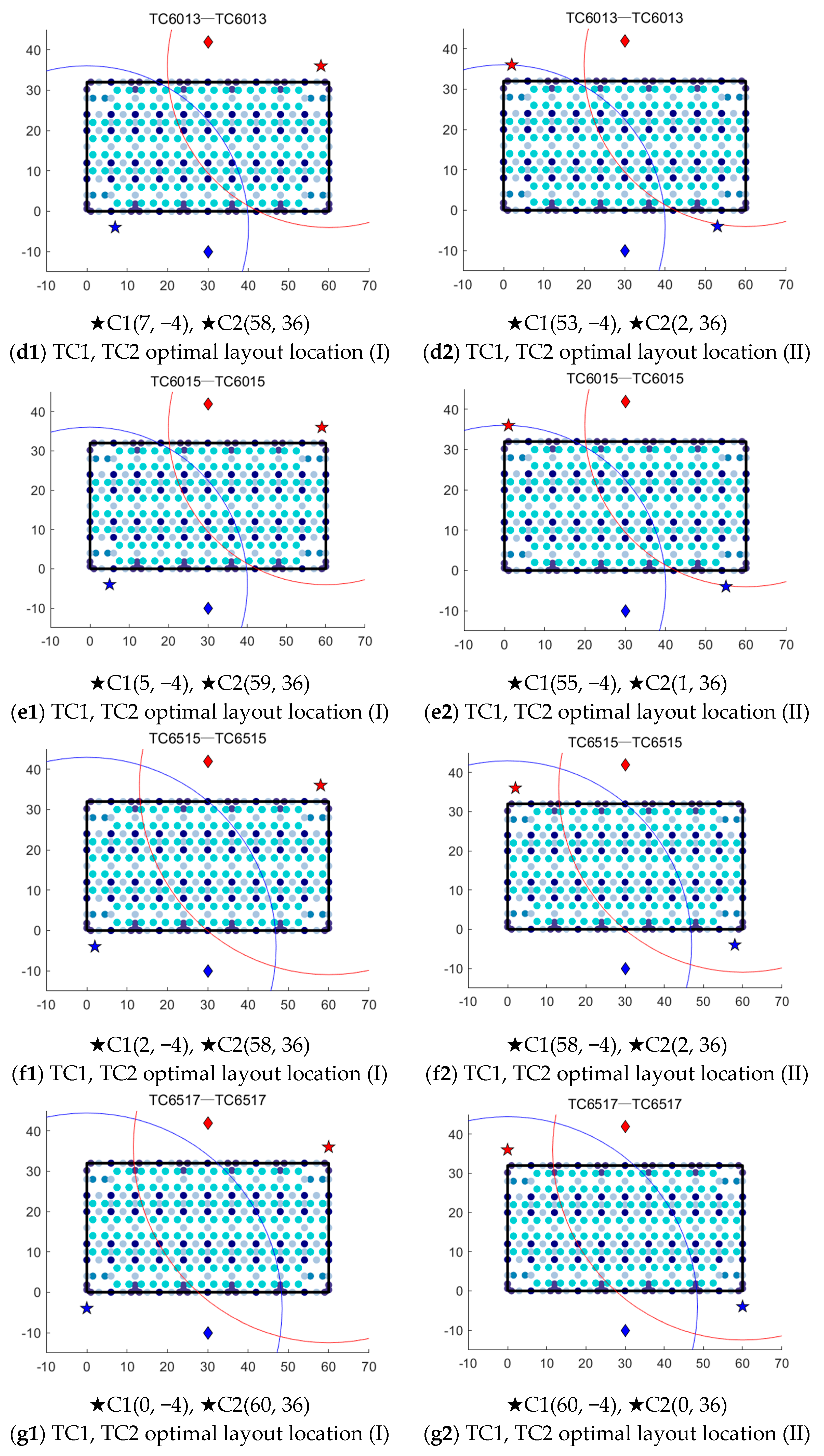
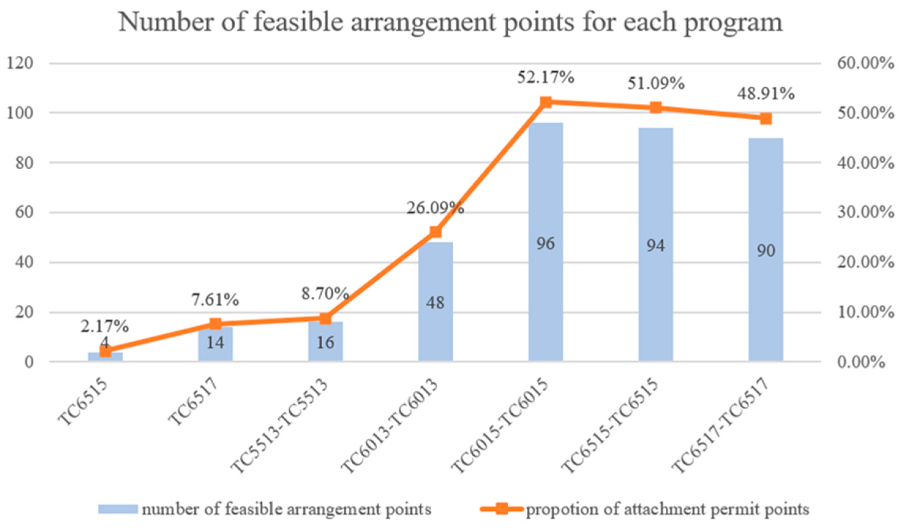
5.1. Analysis of Feasible Layout Area Solution Results of Different Tower Crane Selection Scheme

In the previous section, the feasible layout areas for tower cranes corresponding to the seven types of tower crane selection schemes for the standard floors of the teaching building were calculated and presented in the form of feasible layout points. Based on this, the number of feasible layout points for tower cranes for each selection scheme was statistically analyzed, as shown in Figure 12.
Based on the analysis of Figure 10 and Figure 12, the following points were determined:
The feasible layout area for a single tower crane increased with the size of the tower crane model.
The feasible layout area of the twin tower crane increased with the combination of twin tower crane models and the increase in lifting moment, within a certain range. However, beyond this range, as the boom length increased, constrained by the safety distance between the two-tower crane towers (LTC = 2 m), the feasible layout area gradually decreased, albeit with a small reduction, stabilizing overall.
Among the seven selection schemes, the scheme with the smallest feasible layout area was the one with only one TC6515 (Scheme 1), which had four feasible layout points, accounting for only 2.17% of the permissible attachment points of the tower crane. The scheme with the largest feasible layout area was the one with two TC6015 (Scheme 5), which had 96 feasible layout points, accounting for 52.17% of the permissible attachment points of the tower crane. The feasible layout area of Scheme 5 was 24 times that of Scheme 1.
For the same type of tower crane, the feasible layout area for two cranes was more than six times larger than that for only one crane, such as Scheme 6 (two TC6515) compared to Scheme 1 (TC6515) and Scheme 7 (two TC6517) compared to Scheme 2 (TC6517).

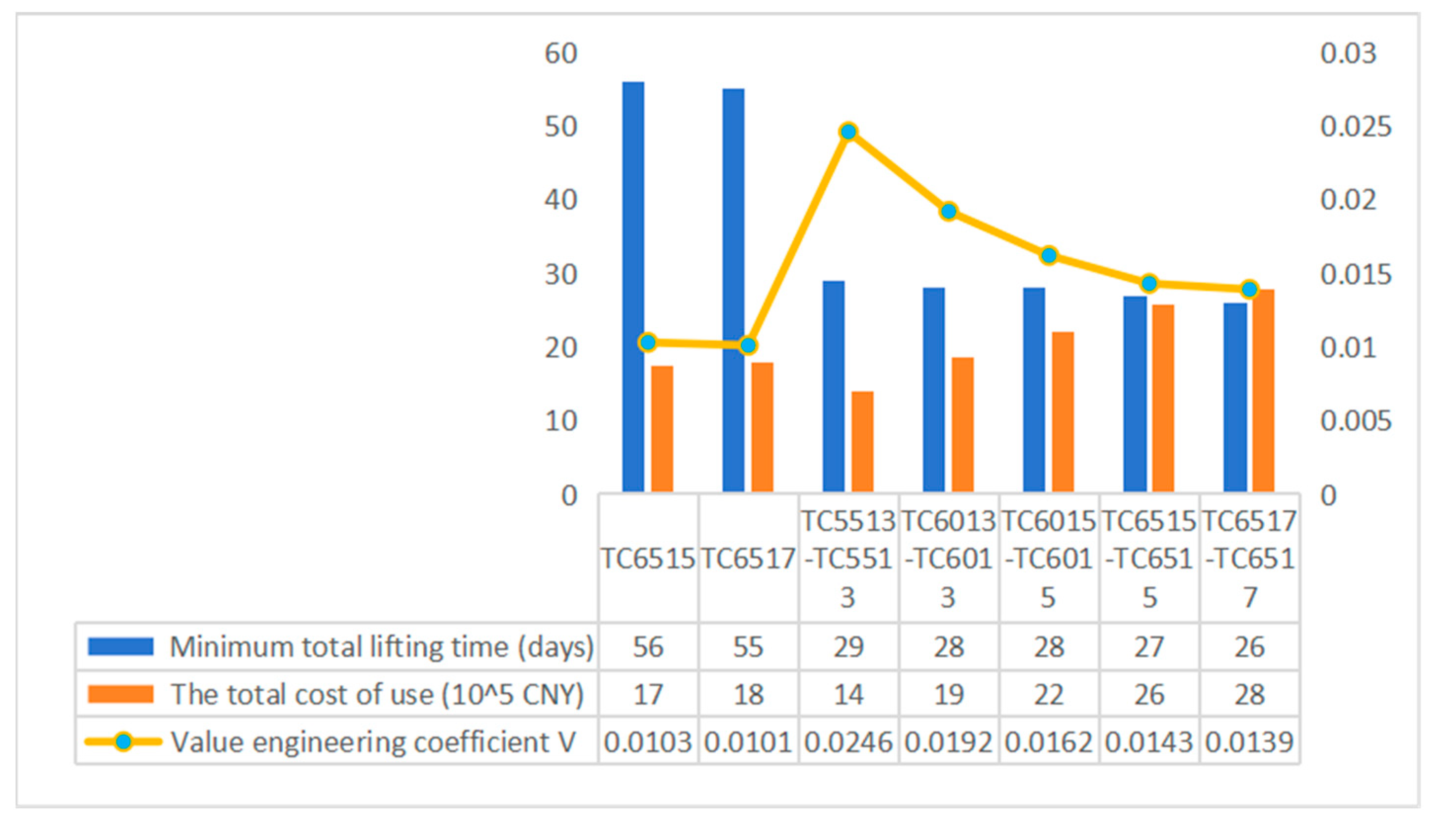
5.2. Comparative Analysis of Optimal Tower Crane Selection and Layout Schemes under Different Objectives

In this section, a comparative analysis of optimal tower crane selection and layout schemes under different objective functions was conducted. According to the results in Table 6, in the case study of this research, the optimal solution corresponding to the shortest total hoisting time for prefabricated components was the TC6517-TC6517 double tower crane scheme, while the optimal solutions corresponding to the minimum usage cost and maximum value engineering coefficient were both the TC5513-TC5513 double tower crane scheme. The solutions of tower crane selection schemes under different objectives are shown in Figure 13.
Based on Table 6 and Figure 13, the following conclusions could be drawn:
In terms of total hoisting time, the TC6517-TC6517 scheme had the shortest hoisting time, at 26 days, and it also had the strongest overall lifting capacity. For both single tower and double tower crane schemes, as the tower crane model size increased, the lifting capacity increased, and the shortest hoisting time for prefabricated components consistently decreased. In the comparison of double tower crane combination schemes, it was observed that although the hoisting time of the smallest model double tower crane scheme was greater than that of the largest model double tower crane, it was only 1.1 times that of the hoisting time of the largest model double tower crane. This indicated that when the smaller model double tower crane could meet the hoisting requirements of the construction site components, the efficiency improvement achieved by selecting the larger model double tower crane scheme was not significant.
In terms of operating costs, the TC5513-TC5513 scheme had the lowest operating cost at 140,000 yuan. Regardless of whether it was a single tower crane scheme or a double tower crane scheme, the total operating costs increased monotonically with the size of the tower crane model. Scheme 3, which used the TC5513-TC5513 double tower crane selection scheme, achieved the minimum operating cost. Its operating cost was lower than that of the single tower crane selection scheme, indicating that this scheme could reduce the total cost by saving leasing fees through time savings. Schemes 1 (single TC6015) and 2 (single TC6017) had relatively lower operating costs compared to Schemes 6 (two TC6015) and 7 (two TC6017). This was because using one less tower crane in the scheme reduced fixed costs such as entrance and exit fees and foundation costs to only 50% of those in the double tower crane selection scheme of the same model. However, the double tower crane selection schemes of the same model did not achieve lower total costs than the single tower crane schemes by reducing leasing fees through shortened hoisting times.
In terms of value engineering coefficient, for the double tower crane combinations, although Scheme 7 (two TC6017) had the shortest hoisting time, its value engineering coefficient was only 0.0139, the smallest among the double tower crane combinations. The value engineering coefficient of two TC5513s (Scheme 3) was the largest (0.0246), which was 1.77 times that of Scheme 7, indicating that Scheme 3 was the optimal choice for this engineering case. Therefore, in actual engineering construction, when the hoisting times of various tower crane selection schemes are similar, selecting the optimal scheme based on the value engineering principle can result in lower costs.

5.3. Comparative Analysis of Single Tower Crane Schemes and Double Tower Crane Schemes Solutions

In traditional construction projects, decision-makers typically opted for a single tower crane when the main parameters of one tower crane sufficed for on-site construction needs. Even in the case study adopted in this paper, certain models of single tower cranes were capable of meeting on-site construction requirements. Combining this observation with the results depicted in Figure 13, a comparative analysis of the solutions for single tower crane and double tower crane configurations can be presented as follows:
In terms of total hoisting time for prefabricated components, the calculated shortest hoisting time for prefabricated components using a single tower crane configuration was significantly longer than that for double tower crane configurations. Employing a double tower crane selection scheme notably enhanced hoisting efficiency, reducing hoisting time. Theoretically, this time savings exceeded 50% compared to single tower crane selection schemes, equivalent to achieving a work efficiency of over double that of single tower crane configurations of the same model (approximately 2.13 times). However, due to overlapping work areas for double tower cranes, there were instances where both cranes could not perform hoisting tasks simultaneously, meaning the hoisting time for a single crane was not precisely twice that of a double crane configuration.
Regarding cost considerations, the cost of employing a single tower crane configuration did not universally surpass those of the double tower crane configurations, with the TC5513-TC5513 scheme demonstrating the lowest usage cost.
Concerning the maximum value engineering coefficient, all single tower crane schemes exhibited coefficients lower than those of double tower crane schemes.
From the above three perspectives of comparison between single tower crane and double tower crane schemes, it could be inferred that in the present research case, adopting a double tower crane scheme proved superior to a single tower crane scheme. This conclusion deviated from the traditional practice of tower crane decision-making, which typically involved the use of only one tower crane when the parameters of a single tower crane sufficed for on-site construction needs. Therefore, the choice between a single or multiple tower cranes was not only based on simplistic considerations of tower crane parameters but also took into account project objectives such as minimizing project duration and costs. A comprehensive evaluation of various schemes was conducted to make informed decisions.

6. Conclusions

To optimize the efficiency and cost of lifting prefabricated concrete components, address the selection and layout optimization of double tower cranes, and reveal the interaction mechanisms between the positioning of double tower cranes, the quality of prefabricated components, storage yards, and installation locations, this study began with the mathematical modeling of feasible placement areas for double tower cranes. Based on this, optimization models were established according to different optimization objectives and solved using genetic algorithms, with implementation performed on the MATLAB 2017b platform. The models were verified and analyzed through a specific engineering case study. The following conclusions were drawn:
For the same construction project, when the location of the component storage yard was known, the feasible placement area for a single tower crane continuously increased as the crane model size increased. However, for double tower cranes, the feasible placement area only increased with the crane model size within a certain range. Due to safety distance requirements, beyond this model range, the feasible placement area slightly decreased as the model size further increased.
After layout optimization, the lifting time for the double tower crane selection scheme was less than 50% of that for the single tower crane selection scheme. The lifting efficiency was more than twice that of a single tower crane of the same model, indicating that using the double tower crane selection scheme in this project could significantly improve construction efficiency.
Unlike construction managers who tended to select single tower crane schemes based on experience, in actual construction projects, if a single small model tower crane was insufficient to complete all lifting tasks, adding another crane of the same model saved more total lifting time compared to replacing it with a larger model. This approach achieved the goal of shortening the construction period. When the lifting times of various tower crane selection schemes were similar, choosing based on the principles of value engineering yielded the optimal solution with lower costs.
This paper integrated theoretical research with engineering practice and proposed a new understanding of tower crane selection. The established mathematical model for feasible layout areas and selection optimization of twin tower cranes was applied in construction processes to effectively improve decision accuracy, enhance construction efficiency, and reduce construction costs.
In future research, the model proposed in this paper could be further optimized in the following aspects: (1) Specific and dynamic formulation of constraints. This study only considered constraints such as the prefabricated component storage area, installation position, and tower crane, as well as factors like lifting distance and height, to simplify the research. However, in actual construction, facing more complex working conditions and environments, there are many factors that affect and limit the placement and application of tower cranes. Therefore, subsequent research needs to comprehensively consider the main conditions and corresponding constraints in the actual construction environment to deepen the preliminary results of this paper. Construction sites are dynamic, and constraints may change with the construction stage, necessitating the development of dynamic models based on the static model proposed in this study. (2) Integration with advanced technologies. Digital twin technology can synchronize and integrate data in real time, combined with sensors, IoT (Internet of Things) devices, and BIM, to more accurately predict and describe the dynamic construction site. This would provide support for MTCLP based on the model proposed in this paper. Artificial intelligence can be used to develop automated crane operation and management systems, combined with the experience of on-site planners and the mathematical model proposed in this paper, to provide optimized solutions for TCLP problems.

Author Contributions

All authors contributed to this study’s conception and design. Material preparation and data collection and analysis were performed by Y.F., J.B., J.L. (Jingjun Lin), C.Z. and J.L. (Jun Liu). The first draft of the manuscript was written by Y.F. and all authors commented on previous versions of the manuscript. All authors have read and agreed to the published version of the manuscript.

Funding

This work was supported by the “Graduate Research and Innovation Foundation of Chongqing, China” under Grant [No. CYS19016]; “the Construction Science and Technology Plan Project of Chongqing” under Grant [No. Construction and Scientific 2023 Project No. 2-1]; “the Youth Project of Science and Technology Research Program of Chongqing Education Commission of China” under Grant [No. KJQN202304302]; and “the Science and Technology Innovation Project in the Field of Housing and Urban Rural Construction in Sichuan Province” under Grant [No. SCJSKJ2022-27].

Data Availability Statement

The original contributions presented in the study are included in the article, further inquiries can be directed to the corresponding author.

Conflicts of Interest

Author Jingjun Lin is employed by the CCCC Urban Investment Holding Co., Ltd. Author Jun Liu is employed by the China Construction Second Engineering Bureau Ltd. The remaining authors declare that the research was conducted in the absence of any commercial or financial relationships that could be construed as a potential conflict of interest.

Appendix A

Table A1. Parameter information table of construction project.
ParametersDescriptions
B x Horizontal coordinates of each vertex of the building outline
B y Vertical coordinates of each vertex of the building outline
R x Horizontal coordinates of each vertex of the construction site boundary line
R y Vertical coordinates of each vertex of the construction site boundary line
D x Horizontal coordinates of DP
D y Vertical coordinates of DP
D z Z coordinates of DP
A t c Available location for the tower crane in the project
Table A2. Tower crane parameter information table.
ParametersDescriptions
TC_nModel of the tower crane
M n Rated lifting moment of the tower crane
L Q _ n Maximum lifting radius corresponding to the lifting capacity Q of the tower crane
L max _ n Maximum lifting radius of the tower crane
L min _ n Minimum lifting radius of the tower crane
enThe real number in the fitting function of the tower crane’s lifting radius Ln and lifting capacity Q
fnThe real number in the fitting function of the tower crane’s lifting radius Ln and lifting capacity Q
Table A3. The quality and installation location information of standard floor prefabricated components of the school construction project.
Types of
Prefabricated Components
Identification Numbers of DPCoordinates of DPThe Mass of the Prefabricated Components (t)
DxDy
Prefabricated columnC1~C56.0, 18.0, 30.0, 42.0, 54.00.02.5
C6~C160.0, 6.0, 12.0, 18.0, 24.0, 30.0,
36.0, 42.0, 48.0, 54.0, 60.0
8.02.5
C17~C270.0, 6.0, 12.0, 18.0, 24.0, 30.0,
36.0, 42.0, 48.0, 54.0, 60.0
12.02.5
C28~C380.0, 6.0, 12.0, 18.0, 24.0, 30.0,
36.0, 42.0, 48.0, 54.0, 60.0
20.02.5
C39~C490.0, 6.0, 12.0, 18.0, 24.0, 30.0,
36.0, 42.0, 48.0, 54.0, 60.0
24.02.5
C50~C546.0, 18.0, 30.0, 42.0, 54.032.02.5
Prefabricated shear wallW1~W101.0, 11.0, 13.0, 23.0, 25.0,
35.0, 37.0, 47.0, 49.0, 59.0
0.01.8
W11~W160.0, 12.0, 24.0, 36.0, 48.0, 60.00.61.8
W17~W220.0, 12.0, 24.0, 36.0, 48.0, 60.01.81.8
W23~W280.0, 12.0, 24.0, 36.0, 48.0, 60.030.21.8
W29~W340.0, 12.0, 24.0, 36.0, 48.0, 60.031.41.8
W35~W441.0, 11.0, 13.0, 23.0, 25.0,
35.0, 37.0, 47.0, 49.0, 59.0
32.01.8
Prefabricated staircaseS1~S41.5, 4.5, 55.5, 58.54.02.6
S5~S81.5, 4.5, 55.5, 58.528.02.6
Prefabricated composite beamB1~B103.0, 9.0, 15.0, 21.0, 27.0,
33.0, 39.0, 45.0, 51.0, 57.0
0.02.5
B11~B210.0, 6.0, 12.0, 18.0, 24.0, 30.0,
36.0, 42.0, 48.0, 54.0, 60.0
4.03.0
B22~B313.0, 9.0, 15.0, 21.0, 27.0,
33.0, 39.0, 45.0, 51.0, 57.0
8.02.5
B32~B420.0, 6.0, 12.0, 18.0, 24.0, 30.0,
36.0, 42.0, 48.0, 54.0, 60.0
10.01.5
B43~B523.0, 9.0, 15.0, 21.0, 27.0,
33.0, 39.0, 45.0, 51.0, 57.0
12.02.5
B53~B630.0, 6.0, 12.0, 18.0, 24.0, 30.0,
36.0, 42.0, 48.0, 54.0, 60.0
16.03.0
B64~B733.0, 9.0, 15.0, 21.0, 27.0,
33.0, 39.0, 45.0, 51.0, 57.0
20.02.5
B74~B840.0, 6.0, 12.0, 18.0, 24.0, 30.0,
36.0, 42.0, 48.0, 54.0, 60.0
22.01.5
B85~B943.0, 9.0, 15.0, 21.0, 27.0,
33.0, 39.0, 45.0, 51.0, 57.0
24.02.5
B95~B1050.0, 6.0, 12.0, 18.0, 24.0, 30.0,
36.0, 42.0, 48.0, 54.0, 60.0
28.03.0
B106~B1153.0, 9.0, 15.0, 21.0, 27.0,
33.0, 39.0, 45.0, 51.0, 57.0
32.02.5
Prefabricated composite panelF1~F167.5, 10.5, 13.5, 16.5, 19.5, 22.5,
25.5, 28.5, 31.5, 34.5, 37.5, 40.5,
43.5, 46.5, 49.5, 52.5
2.01.7
F17~F327.5, 10.5, 13.5, 16.5, 19.5, 22.5,
25.5, 28.5, 31.5, 34.5, 37.5, 40.5,
43.5, 46.5, 49.5, 52.5
6.01.7
F33~F521.5, 4.5, 7.5, 10.5, 13.5, 16.5, 19.5, 22.5,
25.5, 28.5, 31.5, 34.5, 37.5, 40.5,
43.5, 46.5, 49.5, 52.5, 55.5, 58.5
10.01.7
F53~F721.5, 4.5, 7.5, 10.5, 13.5, 16.5, 19.5, 22.5,
25.5, 28.5, 31.5, 34.5, 37.5, 40.5,
43.5, 46.5, 49.5, 52.5, 55.5, 58.5
14.01.7
F73~F921.5, 4.5, 7.5, 10.5, 13.5, 16.5, 19.5, 22.5,
25.5, 28.5, 31.5, 34.5, 37.5, 40.5,
43.5, 46.5, 49.5, 52.5, 55.5, 58.5
18.01.7
F93~F1121.5, 4.5, 7.5, 10.5, 13.5, 16.5, 19.5, 22.5,
25.5, 28.5, 31.5, 34.5, 37.5, 40.5,
43.5, 46.5, 49.5, 52.5, 55.5, 58.5
22.01.7
F113~F1287.5, 10.5, 13.5, 16.5, 19.5, 22.5,
25.5, 28.5, 31.5, 34.5, 37.5, 40.5,
43.5, 46.5, 49.5, 52.5
26.01.7
F129~F1447.5, 10.5, 13.5, 16.5, 19.5, 22.5,
25.5, 28.5, 31.5, 34.5, 37.5, 40.5,
43.5, 46.5, 49.5, 52.5
30.01.7
Note: For prefabricated columns, prefabricated shear walls, and prefabricated staircases, Dz is (n × 3.0), while for prefabricated composite beams and prefabricated composite panels, Dz is (n × 6.0), where n represents the floor number.

References

  1. Ferdous, W.; Bai, Y.; Tuan Duc, N.; Manalo, A.; Mendis, P. New advancements, challenges and opportunities of multi-storey modular buildings—A state-of-the-art review. Eng. Struct. 2019, 183, 883–893. [Google Scholar] [CrossRef]
  2. Hussein, M.; Zayed, T. Crane operations and planning in modular integrated construction: Mixed review of literature. Autom. Constr. 2021, 122, 103466. [Google Scholar] [CrossRef]
  3. Lin, J. Research on Layout Optimization of Double Tower Cranes in Prefabricated Buildings. Master’s Thesis, Chonqing University, Chongqing, China, 2021. [Google Scholar]
  4. Li, H.; Li, X. A Branch-and-Bound Algorithm for the Bi-Objective Quay Crane Scheduling Problem Based on Efficiency and Energy. Mathematics 2022, 10, 4705. [Google Scholar] [CrossRef]
  5. Marzouk, M.; Abubakr, A. Decision support for tower crane selection with building information models and genetic algorithms. Autom. Constr. 2016, 61, 1–15. [Google Scholar] [CrossRef]
  6. Yang, B.; Fang, T.; Luo, X.; Liu, B.; Dong, M. A BIM-Based Approach to Automated Prefabricated Building Construction Site Layout Planning. Ksce J. Civ. Eng. 2022, 26, 1535–1552. [Google Scholar] [CrossRef]
  7. Lien, L.-C.; Cheng, M.-Y. Particle bee algorithm for tower crane layout with material quantity supply and demand optimization. Autom. Constr. 2014, 45, 25–32. [Google Scholar] [CrossRef]
  8. Choi, C.W.; Harris, F.C. A model for determining optimum crane position. Proc. Inst. Civ. Eng. Part 1-Des. Constr. 1991, 90, 627–634. [Google Scholar] [CrossRef]
  9. Nadoushani, Z.S.M.; Hammad, A.W.A.; Akbarnezhad, A. Location Optimization of Tower Crane and Allocation of Material Supply Points in a Construction Site Considering Operating and Rental Costs. J. Constr. Eng. Manag. 2017, 143, 04016089. [Google Scholar] [CrossRef]
  10. Zhang, P.; Harris, F.C.; Olomolaiye, P.O. A computer-based model for optimizing the location of a single tower crane. Build. Res. Inf. 1996, 24, 113–123. [Google Scholar] [CrossRef]
  11. Huang, C.; Wong, C.K.; Tam, C.M. Optimization of tower crane and material supply locations in a high-rise building site by mixed-integer linear programming. Autom. Constr. 2011, 20, 571–580. [Google Scholar] [CrossRef]
  12. Huang, C.; Wong, C.K. Optimization of crane setup location and servicing schedule for urgent material requests with non-homogeneous and non-fixed material supply. Autom. Constr. 2018, 89, 183–198. [Google Scholar] [CrossRef]
  13. Zhang, P.; Harris, F.C.; Olomolaiye, P.O.; Holt, G.D. Location optimization for a group of tower cranes. J. Constr. Eng. Manag. Asce 1999, 125, 115–122. [Google Scholar] [CrossRef]
  14. Dienstknecht, M. A branch and bound approach for the tower crane selection and positioning problem with respect to mutual interference. 4OR Q. J. Oper. Res. 2023, 21, 105–123. [Google Scholar] [CrossRef]
  15. Briskorn, D.; Dienstknecht, M. Covering polygons with discs: The problem of crane selection and location on construction sites. Omega-Int. J. Manag. Sci. 2020, 97, 102114. [Google Scholar] [CrossRef]
  16. Peng, B.; Flager, F.L.; Wu, J. A method to optimize mobile crane and crew interactions to minimize construction cost and time. Autom. Constr. 2018, 95, 10–19. [Google Scholar] [CrossRef]
  17. Ji, Y.; Leite, F. Optimized Planning Approach for Multiple Tower Cranes and Material Supply Points Using Mixed-Integer Programming. J. Constr. Eng. Manag. 2020, 146, 04020007. [Google Scholar] [CrossRef]
  18. Li, R.; Chi, H.-L.; Peng, Z.; Li, X.; Chan, A.P.C. Automatic tower crane layout planning system for high-rise building construction using generative adversarial network. Adv. Eng. Inform. 2023, 58, 102202. [Google Scholar] [CrossRef]
  19. Briskorn, D.; Dienstknecht, M. Mixed-integer programming models for tower crane selection and positioning with respect to mutual interference. Eur. J. Oper. Res. 2019, 273, 160–174. [Google Scholar] [CrossRef]
  20. Khodabandelu, A.; Park, J.; Arteaga, C. Crane operation planning in overlapping areas through dynamic supply selection. Autom. Constr. 2020, 117, 103253. [Google Scholar] [CrossRef]
  21. Wu, K.; de Soto, B.G.; Zhang, F. Spatio-temporal planning for tower cranes in construction projects with simulated annealing. Autom. Constr. 2020, 111, 103060. [Google Scholar] [CrossRef]
  22. Riga, K.; Jahr, K.; Thielen, C.; Borrmann, A. Mixed integer programming for dynamic tower crane and storage area optimization on construction sites. Autom. Constr. 2020, 120, 103259. [Google Scholar] [CrossRef]
  23. Dasovic, B.; Galic, M.; Klansek, U. Active BIM Approach to Optimize Work Facilities and Tower Crane Locations on Construction Sites with Repetitive Operations. Buildings 2019, 9, 21. [Google Scholar] [CrossRef]
  24. Zhang, Z.; Pan, W. Virtual reality supported interactive tower crane layout planning for high-rise modular integrated construction. Autom. Constr. 2021, 130, 103854. [Google Scholar] [CrossRef]
  25. Amiri, R.; Sardroud, J.M.; Kermani, V.M. Decision support system for tower crane location and material supply point in construction sites using an integer linear programming model. Eng. Constr. Archit. Manag. 2023, 30, 1444–1462. [Google Scholar] [CrossRef]
  26. Tam, C.M.; Tong, T.K.L.; Chan, W.K.W. Genetic algorithm for optimizing supply locations around tower crane. J. Constr. Eng. Manag. Asce 2001, 127, 315–321. [Google Scholar] [CrossRef]
  27. Wang, J.; Zhang, X.; Shou, W.; Wang, X.; Xu, B.; Kim, M.J.; Wu, P. A BIM-based approach for automated tower crane layout planning. Autom. Constr. 2015, 59, 168–178. [Google Scholar] [CrossRef]
  28. Zhang, Z.; Pan, W. Multi-criteria decision analysis for tower crane layout planning in high-rise modular integrated construction. Autom. Constr. 2021, 127, 103709. [Google Scholar] [CrossRef]
  29. Javier Irizarry, E.P.K. Optimizing location of tower cranes on construction sites through GIS and BIM integration. J. Inf. Technol. Constr. 2012, 17, 351–366. [Google Scholar]
  30. Huang, C.; Wang, Z.K.; Li, B.; Wang, C.; Xu, L.S.; Jiang, K.; Liu, M.; Guo, C.X.; Zhao, X.F.; Yang, H. Discretized Cell Modeling for Optimal Layout of Multiple Tower Cranes. J. Constr. Eng. Manag. 2023, 149, 04023068. [Google Scholar] [CrossRef]
Figure 1. Plane graph of tower crane.
Buildings 14 01705 g001
Figure 2. Lifting capacity change curve.
Buildings 14 01705 g002
Figure 3. Schematic diagram of tower crane layout range.
Buildings 14 01705 g003
Figure 4. Feasible layout area for TC2.
Buildings 14 01705 g004
Figure 6. Schematic diagram of the material lifting process of a tower crane.
Buildings 14 01705 g006
Figure 8. Building plan of standard floor of a middle school teaching building.
Buildings 14 01705 g008
Figure 9. Prefabricated component supply point, installation point, and tower crane permit attachment point diagram.
Buildings 14 01705 g009
Figure 10. Schematic diagram of feasible layout areas of tower cranes for various selection schemes.
Buildings 14 01705 g010aBuildings 14 01705 g010b
Figure 11. A schematic diagram of the optimal layout position of the hoisting time of each tower crane selection scheme.
Buildings 14 01705 g011aBuildings 14 01705 g011bBuildings 14 01705 g011c
Figure 12. Schematic diagram of the size of the feasible layout area of tower cranes in various selection schemes.
Buildings 14 01705 g012
Figure 13. Calculation results of tower cranes for different selection schemes under different objectives.
Buildings 14 01705 g013
Table 1. The literature on tower crane layout optimization.
No.Research ObjectsResearch ObjectivesImproved Mathematical Modeling 1Optimization AlgorithmAuxiliary ToolsResearch
1Single Tower CraneMinimizing total costMIP\ 2\Nadoushani [9]
2Minimizing total costMILP\BIMBriskorn [19]
3Minimizing total cost\SA\Wu [21]
4Minimizing total costILP\\Amiri [25]
5Minimizing total time\\GANLi [18]
6Minimizing total cost and time\GA\Tam [26]
7Minimizing total cost and timeMIP\\Ji [17]
8Shortest hook movement distanceBMIP\\Huang [12]
9Multiple Tower CranesMinimizing total cost\PSO\Lien and Cheng [7]
10Minimizing total time\FABIMWang [27]
11Safety and minimizing total time\\Fuzzy Analytic Hierarchy ProcessZhang [28]
12Safety and minimizing total time\\VRZhang [24]
13Balancing workload and minimizing path conflicts\\\Zhang [13]
14Minimizing path conflicts and maximizing coverage area\\BIM&GISIrizarry [29]
15Minimizing path conflicts and minimizing idle time\GABIMMarzouk [5]
16Precisely describing irregularly shaped sites and buildingsMILP\\Huang [30]
1 Improved Mathematical Modeling refers to the improvements made based on Zhang’s model in [13]. 2 The slash (\) represents the fact that it is not covered in this article.
Table 2. Parameters and descriptions.
ParametersDescriptions
r D C Horizontal projection distance from FP to DP
r S C Horizontal projection distance from FP to SP
r S D Horizontal projection distance from DP to SP
L Q Jib radius
v ω Rotation speed of the tower crane
θ Rotation angle of the tower crane
T r Time for trolley to complete radial movement
T ω Time for jib to complete horizontal rotation
v r 1 Speed of the trolley moving radially while loaded
v r 2 Speed of the trolley moving radially while unloaded
α Coordination degree between trolley motion and jib rotation
T h Total horizontal movement time
h 0 Safety height
T u p Lifting time
T d o w n Lowering time
T V Total vertical movement time
V v 1 Vertical movement speed of loaded tower crane
V v 2 Vertical movement speed of unloaded tower crane
z d Z-coordinate of DP
z s Z-coordinate of SP
γ Coordination level between horizontal and vertical movements of the tower crane
T C Time to complete all lifting tasks
T u n l o a d Unloading time of the hook at DP
T l o a d Loading time of the hook at SP
T t o t a l Total time of the project lifting works
T 1 Total lifting time of TC1
T 2 Total lifting time of TC2
I 1 Number of components handled by TC1
I 2 Number of components handled by TC2
J Number of floors requiring lifting operations
T 1 x c 1 , y c 1 Time for a single lifting task when TC1 is located at ( x c 1 , y c 1 )
T 2 x c 2 , y c 2 Time for a single lifting task when TC2 is located at ( x c 2 , y c 2 )
C t o t a l Total operation cost of the tower cranes
C t c 1 Operating cost of TC1
C t c 2 Operating cost of TC2
C F 1 Cost of foundation construction for TC1
C F 2 Cost of foundation construction for TC2
C I 1 Cost of installation and dismantling for TC1
C I 2 Cost of installation and dismantling for TC2
C R 1 Rental cost per day for TC1
C R 2 Rental cost per day for TC2
V Value engineering coefficient
Table 3. Information regarding the prefabricated component yards.
Title 1Coordinates of Supply Points
SxSy
SP130.042.0
SP230.0−10.0
Table 4. Attached tower crane performance parameter information table.
Parameter
Information
Tower Crane Models
TC5513TC6013TC6015TC6515TC6517
Maximum lifting height H max (m)150150150150150
Maximum lifting boom width L max (m)5560606565
Minimum lifting boom width L min (m)2.52.52.52.52.5
Lifting boom length R (m)5661.0361.7466.0066.75
Maximum lifting capacity (t)86101212
Rotation speed v ω (rad/min)4.44.44.44.44.4
Load variation speed v r 1 (m/min)2025252525
No-load variable speed v r 2 (m/min)5055555555
Load take-off and landing speed v v 1 (m/min)40507080100
No-load take-off and landing speed v v 2 (m/min)100100100100100
Rental fees C r (RMB/d)6001000130015001600
Access and installation costs C I (RMB)32,00040,00045,00055,00060,000
Basic production costs C F (RMB)21,00025,00029,00035,00038,000
Table 5. Tower crane selection scheme for school building construction project.
Scheme NumberTower Crane Model Combination
1TC6515
2TC6517
3TC5513-TC5513
4TC6013-TC6013
5TC6015-TC6015
6TC6515-TC6515
7TC6517-TC6517
Table 6. The total time required to complete the lifting of the components of each selection scheme.
Selection SchemesTower Crane Model CombinationOptimal Timing
Positioning (I), (II)
Minimum Total Lifting Time Min (Ttotal)The Total Cost of Use (CNY)Value Engineering Coefficient V
1TC6515C1(30, 36)\26,607.06173,147.070.0103
2TC6517C1(30, 36)\26,193.57179,854.920.0101
3TC5513-TC5513C1(9, −4)
C2(57, 36)
C1(51, −4)
C2(3, 36)
13,766.99140,417.480.0246
4TC6013-TC6013C1(7, −4)
C2(58, 36)
C1(53, −4)
C2(2, 36)
13,376.73185,736.380.0192
5TC6015-TC6015C1(55, −4)
C2(1, 36)
C1(5, −4)
C2(59, 36)
13,307.26220,080.990.0162
6TC6515-TC6515C1(2, −4)
C2(58, 36)
C1(58, −4)
C2(2, 36)
12,507.29258,170.570.0143
7TC6517-TC6517C1(0, −4)
C2(60, 36)
C1(60, −4)
C2(0, 36)
12,244.21277,628.070.0139
Disclaimer/Publisher’s Note: The statements, opinions and data contained in all publications are solely those of the individual author(s) and contributor(s) and not of MDPI and/or the editor(s). MDPI and/or the editor(s) disclaim responsibility for any injury to people or property resulting from any ideas, methods, instructions or products referred to in the content.

