Article

Study on Strong Earthquake Failure of Single-Layer Spherical Reticulated Shell Structures with Central Suspended Equipment

1
College of Civil Engineering and Architecture, Northeast Electric Power University, Jilin 132000, China
2
Key Lab of Structure Dynamic Behaviour and Control of the Ministry of Education, Harbin Institute of Technology, Harbin 150090, China
3
Key Lab of Smart Prevention and Mitigation of Civil Engineering Disasters of Ministry of Industry and Information Technology, Harbin Institute of Technology, Harbin 150090, China
*
Author to whom correspondence should be addressed.
Buildings 2024, 14(6), 1706; https://doi.org/10.3390/buildings14061706
Submission received: 25 April 2024 / Revised: 23 May 2024 / Accepted: 3 June 2024 / Published: 7 June 2024
(This article belongs to the Section Building Structures)

Abstract

:
In recent years, there have been more and more engineering examples of installing giant suspended equipment (e.g., central suspended LED display) in large-span space structures; however, there are fewer studies on the seismic response and strong-seismic failure process of large-span space structures after the addition of central suspended equipment. In this paper, changes in the nodal displacements of the reticulated shell structure before and after the addition of the central suspended equipment, the proportion and distribution characteristics of the plastic shell members, and the strong seismic deformation of the reticulated shell structures are taken as indexes under the different ground motions. This paper analyses the influence characteristics of the suspended equipment on the seismic response of Kiewitt K-8 single-layer spherical reticulated shell structures and reveals the influence laws of suspended equipment with different masses on the displacement of mounting nodes and the nodes in other rings in the reticulated shell structure. Based on the plastic degree development analysis of the structures under strong ground motion, the paper analyses the failure mechanism of the reticulated shell structures with central suspended equipment and summarizes two typical failure modes. The paper analyses the influence laws and characteristics of different factors (span, rise-to-span ratio, different seismic loads and the length of suspended cables) on the seismic response of the reticulated shell structures with central suspended equipment.

1. Introduction

In large-span space structures, there is often a large mass of equipment (e.g., LED display screen) hanging in the centre of the structure, and the weight of the suspended equipment often reaches several tonnes [1]. It has been shown that when the mass of equipment added to the main structure exceeds 0.1% of the mass of the main structure, its influence on the seismic response of the main structure cannot be ignored [2]. Therefore, it is necessary to study the seismic response and strong earthquake failure mechanism of large-span space structures with suspended equipment. Currently, seismic response analyses for main structures with heavy suspended equipment have focused on high-rise reinforced concrete frame structures, cylinder structures, and towering structures [3,4,5]. It is common for scholars to analyse the effect of a suspended mass placed inside the structure on the dynamic response of the main structure according to a pendulum-tuned mass damper. Fernando et al. [6] analysed the influence mechanism of a tuned mass damper (TMD; the range of mass ratio is 0.5–2.5%) on the dynamic response of a single-degree-of-freedom main structure and analysed the effect of different damper parameters on the displacement response of the main structure. Zheng et al. [7] further analysed the influence of TMD (the range of mass ratio is 0.5–10%) on the dynamic properties of multi-degree-of-freedom systems and investigated the displacement response of high-rise buildings with TMD under wind loads, using the structural displacement response variance ratio as an indicator to optimise the TMD parameters. Based on the above research, it was found that the suspended mass element has a significant effect on the dynamic response of multi-storey and high-rise buildings, so some scholars have also carried out research on the influence of suspended mass element on the dynamic performance of large span space structures. Ye et al. [8,9] applied the theory of tuned mass damper to analyse the dynamic response of large-span space structures (the average mass ratio is 1–2%), and investigated the influence of mass-tuned mass damper on the dynamic characteristics of single-layer spherical reticulated shell structures. Hu et al. [10] further analysed the effect of suspended mass element on the wind vibration response of a spherical reticulated shell structures (the average mass ratio is 5%), and analysed the optimization parameters of the suspended mass element for the wind vibration response of the shell. The above studies are based on the vibration reduction effect of suspended mass dampers to analyse the influence of suspended mass element on the dynamic performance of large-span space structures, and optimise the arrangement scheme of suspended mass element. On the other hand, in practical engineering, the situation of central suspended equipment in large-span spatial structures is more common, and whether central suspended equipment can play a seismic reduction effect needs to be further studied. Liu et al. [11,12] investigated the seismic response of single-layer spherical reticulated shell structures with suspended display screen under three-direction earthquakes and found that the suspended equipment changes the self-oscillation characteristics of the shell structure and increases the internal forces in the shell members and the magnitude of nodal accelerations. Xue et al. [13,14] conducted a vibration table test on a tension string structure with a central suspended display screen and found that the suspended display screen has a significant impact on the structural vibration response, pointed out the influence of the suspended display screen needs to be considered in the design stage of the structure.
The above studies provide valuable experience in analysing the influence of suspended equipment on the seismic response of reticulated shell structures, but there are still some issues that need to be analysed in depth. Firstly, scholars have generally analysed the vibration reduction effect of suspended mass element on the dynamic performance of the high-rise frame structures, but this is different from the situation of a reticulated shell structure with central suspended equipment. Although the additional mass (such as central suspended equipment) does not alter the static bearing capacity and design scheme of the reticulated shell structure, the suspended equipment will affect the seismic performance of the reticulated shell structure by changing the higher-order vibration modes, which is different from the situation in high-rise frame structures. On the other hand, if the mass of central suspended equipment is relatively larger, approximately equal to 50% of the node mass, the installation positions of the suspended equipment are also relatively fixed, which would cause local damage to the reticulated shell structure. The above differences will result in existing studies not being suitable for seismic response analysis of reticulated shell structures with central suspended equipment. In addition, although some scholars have analysed the seismic performance of reticulated shell structures with central suspended equipment, the research mainly focuses on the influence of suspended equipment on the acceleration of the shell nodes and the internal force of shell members. There is still a gap in the research on the seismic response and failure process of reticulated shell structures with suspended equipment under strong seismic actions.
In this paper, the analysis of the seismic response and strong earthquake failure process of the Kiewitt K-8 single-layer spherical reticulated shell structures with suspended equipment are carried out; the reticulated shell structures are supported on the ground directly. Firstly, based on the typical examples, the paper analyses the influence of suspended equipment connected by single steel pipe and steel cables on the seismic response of single-layer reticulated shell structures respectively. Secondly, the paper analyses the influence characteristics of suspended equipment in the elastic and plastic stages of the reticulated shell structures on the seismic performance of the whole structures and summarizes two typical failure modes. Finally, the paper analyses the influence law of the different factors (the span, the rise-to-span ratio, different ground motion and the length of the suspended cables) on the seismic response of the reticulated shell structures with suspended equipment.

2. Methodology

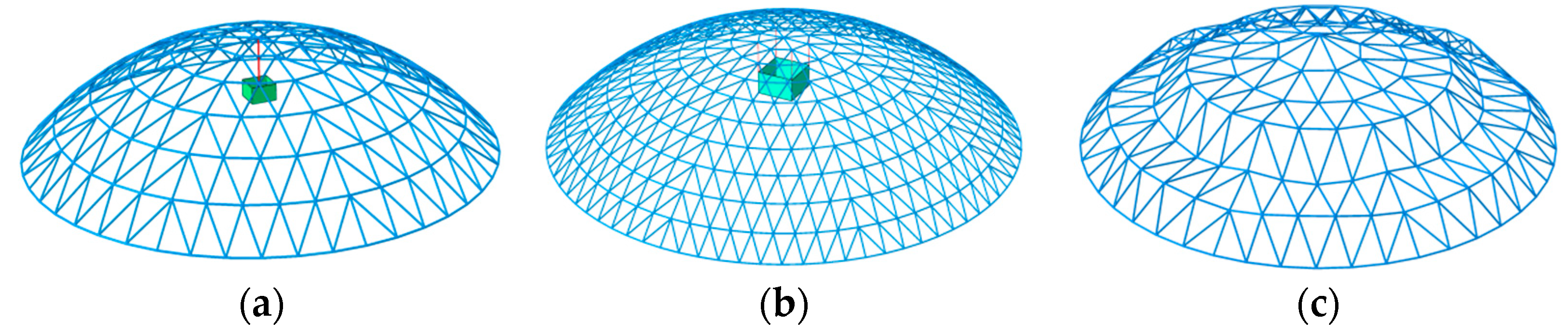
2.1. Finite Element Model of a Shell with Suspended Equipment

In this paper, the main structure is a Kewitt K8 single-layer spherical reticulated shell structure, with spans of 40 m, 80 m, 100 m, and 120 m, and the rise-to-span ratio is taken as 1/3, 1/5, and 1/7, respectively. The roof load is taken as the constant load of 155 kg/m2 and the live load as 50 kg/m2, respectively. According to the safety factor and stiffness requirements of the specifications [15], the cross-section of the shell members and ring number of shell are shown in Table 1.
In large-span space structures, central suspended equipment (LED display screen) is generally installed in steel frames which are connected to the node of the main structure by steel pipe or steel cable. The two connections are related to the size and weight of the LED display screen [16,17]. For different span of the reticulated shell structure, it is necessary to use different sizes of display screen to meet the requirements of the visual distance for the shell with small span (the span is 40 m in this paper). Due to its small size and the light weight of the suspended display screen, a single steel pipe is used to connect the suspended equipment (LED display screen) to the centre node of the shell. For a shell with a larger span (such as 80 m), the size and weight of the display screen is larger, and steel cables are used to connect the suspended equipment to the nodes in the first ring near the centre node of the shell. According to existing research statistics [1], the weight range of suspended display screen equipment is between 45 kg/m2 and 183 kg/m2; in this paper, the weight of the display screen is 60 kg/m2.
x 2 + y 2 + z + R f 2 = R 2
In finite element analysis, the node coordinate function of the Kiewitt K8 single-layer reticulated shell structure is shown in the Equation (1) [18], where x (y and z) is the spatial coordinates of the reticulated shell nodes, R is the curvature radius, and f is the height of reticulated shell structure. The finite element models of the reticulated shell structures are established in Abaqus 6.13 finite element software based on Python program application. In finite element models, beam elements (B31) are used to simulate the shell members and the steel pipe which is used to connect the shell centre node and suspended equipment, the constitutive model of shell members and steel pipe is an ideal elastic–plastic model, with an elastic modulus of 206 GPa and a yield strength of 235 MPa. The steel cable is a 26 mm diameter wire rope, with an elastic modulus of 103 Gpa and a Poisson’s ratio of 0.25, the truss (T3D2) element is used to simulate steel cable, and the cable is assigned a tensile-only material property. The finite element analysis model is shown in Figure 1a,b. According to existing studies, when the initial defect mode of a single-layer reticulated shell structure is the first eigenvalue buckling mode, the load-bearing capacity of the reticulated shell structure is usually the lowest [19,20]. Therefore, the first eigenvalue buckling mode of the shell is used as the initial defect mode of the model. The initial defect mode only considers defects at node positions, without considering the initial bending of the shell members, as shown in Figure 1c. The defect amplitudes are selected as L/1500.

2.2. The Finite Element Analysis Method

This paper uses the incremental dynamic time history analysis method (IDA, the peak value of seismic acceleration is used as a scaling parameter) in the full load domain to analyse the strong earthquake failure process of the reticulated shell structures with a suspended equipment (central suspended display screen). On the basis of incremental dynamic time history analysis of reticulated shell structure, we analyse the seismic performance analysis indicators of reticulated shell structures underground motions with different acceleration amplitudes. The analysis indicators include the maximum relative displacement Umax of the nodes in reticulated shell structures under seismic action, the proportion and distribution of plastic members in the reticulated shell structures, and the deformation of the whole structure. As shown in Equations (2) and (3), where Ui is the relative displacement of the i-th node of the reticulated shell structure, u i , X 0 and u i , X N are the absolute displacement in the X-direction before and after the seismic action of the i-th node of the shell, respectively. The material non-linearity and geometric non-linearity of the reticulated shell structure are considered in finite element analysis. The plasticity type of the shell member is based on hysteretic models. As shown in Figure 2a–d, the cross-section of the reticulated shell member is divided into 8 integral points; if one integral point of cross-section of a shell member enters plasticity, the shell member is counted as a 1P plastic member; if all 8 integral points of cross-section of a shell member enter plasticity, the member is counted as an 8P plastic shell member. The calculation of the proportion of plastic shell members is shown in Equations (4) and (5), where N1P is the number of 1P shell members, N1 is the proportion of the number of N1P, N3P, N5P, and N8P members to the total number of the shell members (Ntotal), and N8 is the proportion of the number of N8P members to the total number of the shell members.
U i = u i , X N u i , X 0 2 + u i , Y N u i , Y 0 2 + u i , Z N u i , Z 0 2
U max = max U 1 , U 2 , U 3 , , U i , U n
N 1 = N 1 P + N 3 P + N 5 P + N 8 P N t o t a l
N 8 = N 8 P N t o t a l
The seismic responses of the reticulated shell structure are different under the action of different ground motions, the reticulated shell structure is a vibration mode-intensive structure, and the higher-order vibration mode has a significant effect on its seismic responses [21,22]. On the other hand, due to the long self-oscillation period of the suspended equipment, the lower-frequency vibration will cause the resonance phenomenon of the suspended equipment and will aggravate the vibration response of the reticulated shell structures. Therefore, it is necessary to analyse the influence of different ground motions on the seismic response of the reticulated shell structure with suspended equipment. This paper selects 14 ground motions and analyses their spectral characteristic values (βl) as shown in Equation (6) [23], where Sa(Ti) is the seismic acceleration response spectrum value, Ti is the period interval corresponding to the seismic acceleration response spectrum, and PGA is the peak value of seismic acceleration. When the βl value of the ground motion is less than 0.2, the seismic motion is a shorter period ground motion (ordinary ground motion), when the βl value of the ground motion is greater than 0.2, the ground motion is a medium or long period ground motion (longer-period ground motion). The ground motion information is shown in Table 2.
β l = T i 2 S a T i P G A T i 2

3. Results and Discussion

3.1. Analysis of the Influence Mechanism of Suspended Equipment

In this section, an analysis of the seismic response of a reticulated shell structure with suspended equipment under three-direction ground motion (Taft, 1952) is carried out using D407 and D805 reticulated shell structures as examples. The reticulated shell D407-W refers to the shell D407 without suspended equipment, and the reticulated shell D407-SE refers to the shell D407 with suspended equipment. The reticulated shell D407-SE connects the suspended equipment to the centre node of the shell with steel pipe (single-node steel pipe connection), while the reticulated shell D805-SE connects the suspended equipment to the first ring nodes near the centre node of the shell with steel cables (steel cable connection). Comparison of the influence of the suspended equipment on the maximum nodal displacements of the reticulated-shell structure and the degree of plastic shell members development are shown in Figure 3 and Figure 4.
As shown in Figure 3a, it can be seen that the influence of the suspended equipment on the Umax of the reticulated shell structures shows a fluctuating trend. To provide a clearer analysis of the influence of suspended equipment, in this paper, the seismic influence coefficient γ of the suspended equipment on the reticulated shell structure is used to express the influence of the suspended equipment on the deformation of the reticulated shell structures under all levels of seismic loading, as shown in Equation (7), where U max , shell and U max , SE are the maximum relative displacements of the nodes in the reticulated shell structures before and after the addition of the suspended equipment, and γj represents the seismic influence coefficient of suspended equipment on the j-th ring nodes in the reticulated shell structure, as shown in Equation (8).
γ = U max , shell U max , SE U max , shell × 100 %
γ j = U j , max , shell U j ,   max , SE U j ,   max , shell × 100 %
As shown in Figure 3b,c, when the seismic acceleration amplitude is less than 1 g, the plastic development degree of the reticulated shell members is relatively lower, the proportion of 1P plastic shell members is less than 40% (N1 ≤ 40%, N8 ≤ 2.5%), the suspended equipment of the two kinds of connections (single-node steel pipe connection and steel cable connection) reduce the Umax of the shell D407 and D805 by 0% to 7.2% and 2.1% to 7.7%, respectively, and the vibration reduction effect of suspended equipment with steel cable connection is more significant for the typical example D805. When the seismic acceleration amplitude reaches 1.2 g, the plastic development degree of the shell D805-SE significantly deepens (N1 ≈ 60%, N8 ≈ 36%), and the suspended equipment with a steel cable connection even increases the Umax of the shell by 1%. On the other hand, the plastic development degree of D407-SE is still relatively lower (N1 < 40%, N8 ≈ 13.3%), the vibration reduction effect of the equipment with a single-node steel pipe connection is more obvious for the typical example D407,which reduces the Umax of the shell by 5% and reduces the proportion of 8P plastic shell members (N8) by 3%.
As shown in Figure 5a–c, when the proportion of the 1P plastic shell members is less than 60% (N1 ≤ 60%), the fluctuation range of the seismic influence coefficients (γ) of the suspended equipment with single-node steel pipe connection on the three kinds of rise-to-span ratios (1/7, 1/5, and 1/3) reticulated shells with the span of 40 m are −22.8~27%, −12~5.8%, and −1.4~1.8%, respectively. It can be found that the fluctuation range of the coefficient (γ) of suspended equipment with single-node steel pipe connection decreases with the increase of the rise-to-span ratio of the shell. This is because suspended equipment with a single-node steel pipe connection is only used in reticulated shell structures with a small span (40 m), and suspended equipment with a single-node steel pipe connection has a smaller influence on the horizontal seismic response of other nodes of the reticulated shell structures. As the rise-to-span ratio increases, the vertical stiffness of the reticulated shell structure increases, the influence of the suspended equipment on the vertical seismic response of the reticulated shell structure with a larger rise-to-span ratio is not obvious.
As shown in Figure 5d–f, for the large-span (80 m) reticulated shell structure with steel cable connection suspended equipment, when the plastic development degree of the reticulated shell structure is shallow (N1 ≤ 40%), the suspended equipment with steel cable connection has the minimum vibration reduction influence on the reticulated shell structure with a 1/3 rise-to-span ratio. However, as the plastic development degree of the reticulated shell structures increases (N1 > 40%), suspended equipment with a steel cable connection has the largest fluctuation range of γ on the 1/3 rise-to-span ratio reticulated shell structure. This is because the steel cable connection only bears tension and not pressure; under the action of three-direction ground motion, suspended equipment always applies a downward load on the mounting node of a reticulated shell structure. When the amplitude of seismic acceleration is small, the effect of suspended equipment on reticulated shell structures with high vertical stiffness (such as 1/3 rise span ratio) is relatively small. When the seismic acceleration amplitude is large, the plastic development degree of the reticulated shell structure gradually deepens, and the suspended equipment significantly affects the horizontal seismic response of the nodes of the reticulated shell structure with 1/3 rise-to-span ratio through more severe swinging.
To further analyse the influence of suspended equipment, this paper separately analyses the reticulated shell structures with suspended equipment on the elastic stage and failure stage.

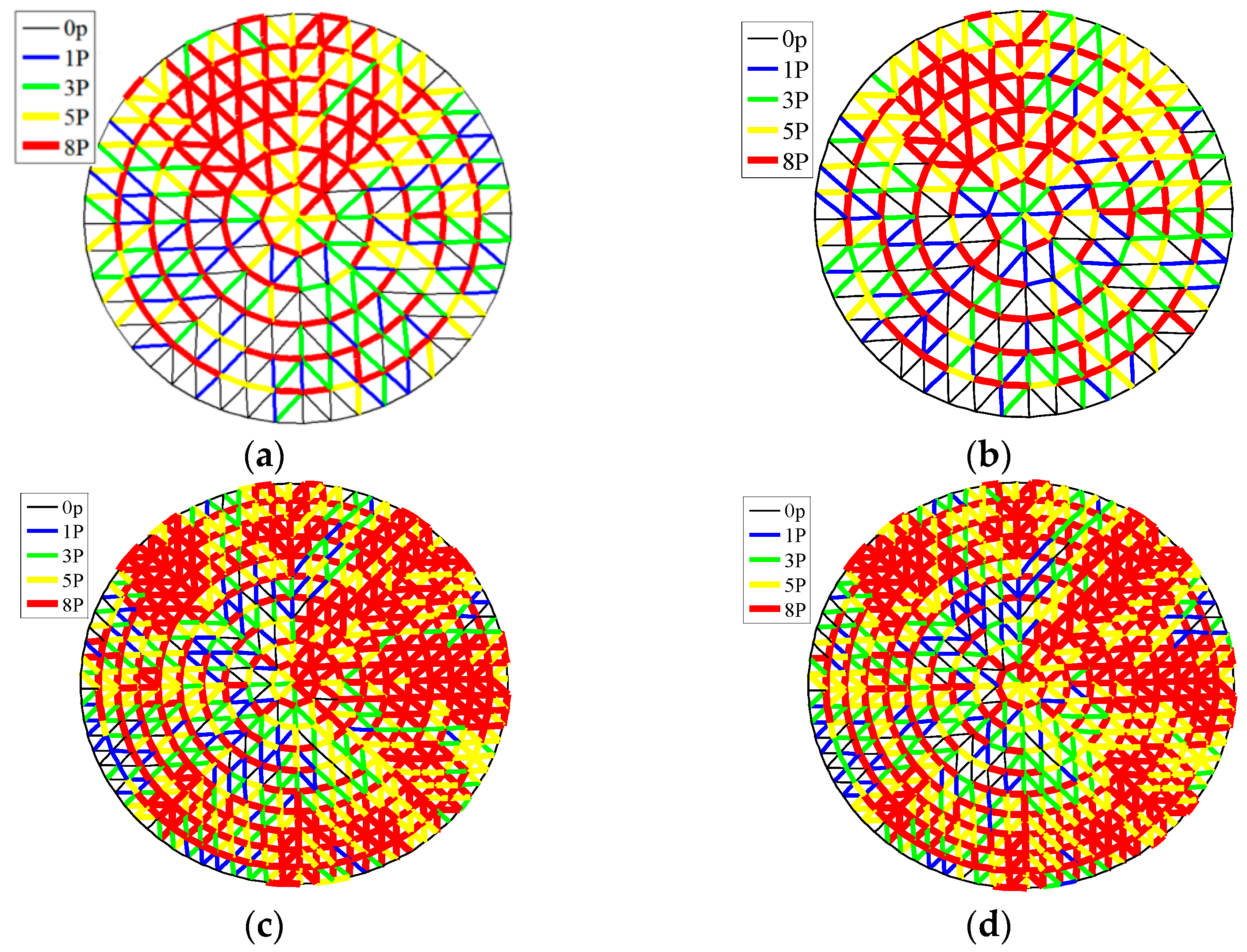
3.1.1. Elastic Stage Analysis

When the seismic acceleration amplitude is small, both the single-node steel pipe connection and the steel cable connection of the suspended equipment undergo slight oscillation under seismic action, and the influence mechanism of the two kinds of connections on the displacement response of the reticulated shell nodes are basically the same. The paper compares the average value of γj in each ring of a 40 m and 80 m span reticulated shell structure under seismic action with an acceleration amplitude of 0.2 g and analyses the influence of suspended equipment on the elastic stage of the reticulated shell structures. The weight of the suspended equipment is taken as 50%, 100%, and 150% of the weight of the suspended equipment in Table 1.
As shown in Figure 6a–c, the influence of suspended equipment with single-node steel pipe connections on the displacement of the centre node of a 40 m span reticulated shell structure is significant. The suspended equipment reduces the displacement of the mounting node of the shell by three different rise-to-span ratios (1/7, 1/5, 1/3); the ranges of γ1 are 20~35%, 23~26%, 0.5~2.3%, and the γj of other rings are almost zero. As shown in Figure 6d–f , suspended equipment with steel cable connections significantly increases the displacement response of the mounting nodes of an 80m span reticulated shell structure with three different rise span ratios. The values of γj of other ring nodes show a trend of first increasing and then decreasing outward from the 2nd or 3rd ring around central node, in which the vibration reduction region of the shell D805 is the 3rd ring to the 6th ring nodes of the reticulated shell structure, the shell D805 has the widest range of vibration reduction region. By comparing the values of γj in each ring of the reticulated shell structure with different masses of suspended equipment, it can be found that when the reticulated shell structure is in the elastic phase, the larger the mass of the suspended equipment, the more obvious its effect of reducing node displacement in the vibration reduction region of the reticulated shell structure, but at the same time, it also exacerbates the node displacements in other rings of the reticulated shell structures.

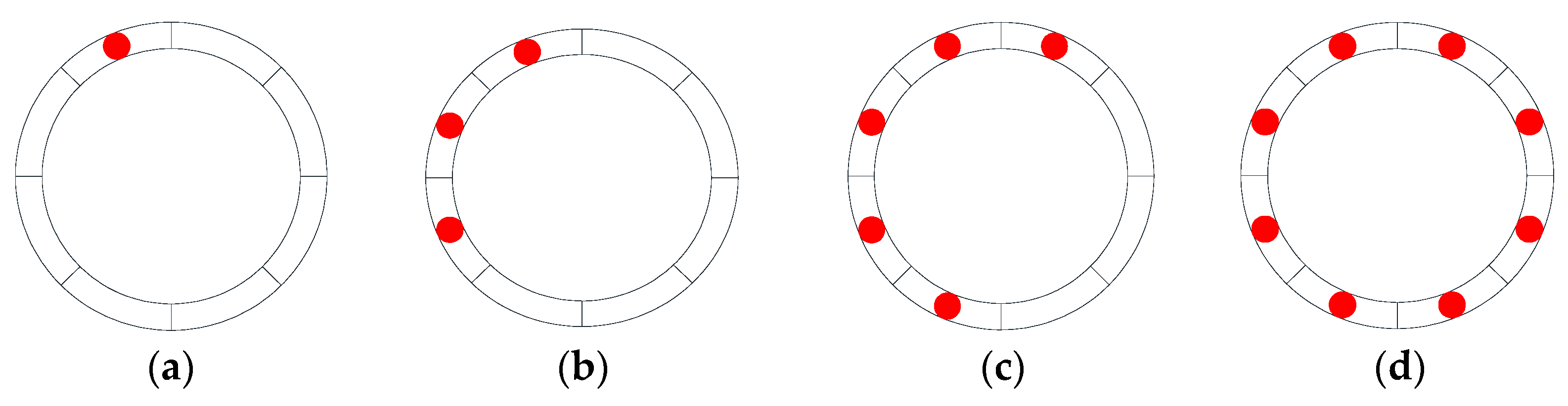
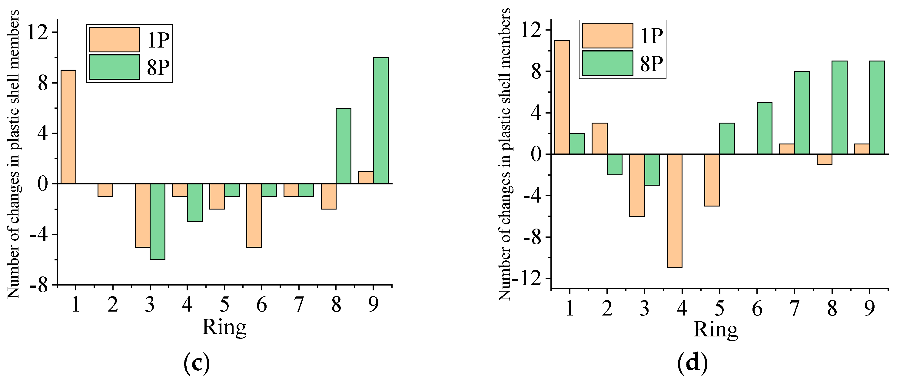
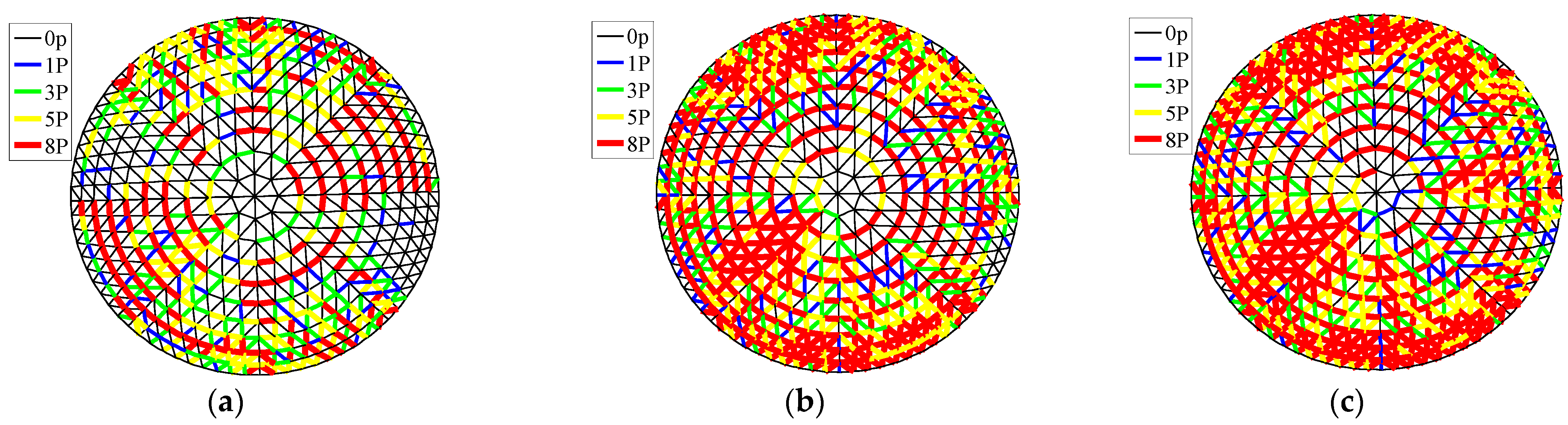
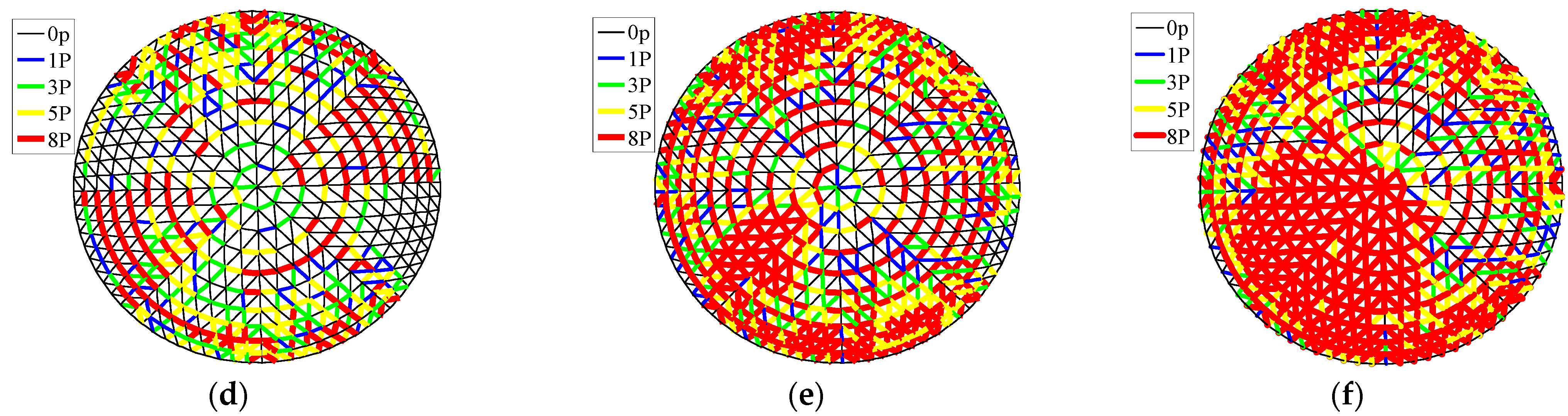
3.1.2. Failure Stage Analysis

With the increase of seismic acceleration amplitude, the proportion of plastic shell members in the reticulated shell structure increases, and the influence of the suspended equipment on the seismic performance of the reticulated shell structure also shows a more dramatic fluctuation change. By analysing the strong seismic response of the reticulated shell structure with suspended equipment, it is found that the failure modes of the 40m span reticulated shell structures with single-node steel pipe connected suspended equipment are unchanged, while suspended equipment with steel cable connection would cause a change in the strong seismic failure mode of the reticulated shell structure. The typical failure modes can be divided into the following two types.
(1)
Failure Mode 1
Failure mode 1 shows that under seismic action, the suspended equipment changes the distribution of plastic shell members of the reticulated shell structures by swinging, but the location of the reticulated shell structure where the Umax occurs does not change, and when the seismic damage limit load is reached, the suspended equipment aggravates the deformation of the reticulated shell structure, which leads to the collapse of the reticulated shell structure. As shown in Figure 7a, under the action of GM-3 ground motion with an acceleration amplitude of 1.2 g, the suspended equipment has a significant vibration reduction influence on the shell D803 (γ = 34%), and under the action of GM-3 ground motion with an acceleration amplitude of 1.8 g, the deformation of the reticulated shell structure D803 significantly increases (γ = −37%), but the position of the maximum deformation does not change. When the seismic acceleration amplitude is 2 g, the reticulated shell structure D803-SE experiences large-scale collapses first, as shown in Figure 7).
As shown in Figure 7b,c and Figure 8, the suspended equipment causes changes in the distribution of plastic shell members in each ring of the reticulated shell structure D803. Under GM-3 ground motion with an acceleration amplitude of 1.2 g, the suspended equipment increased 9 plastic shell members in the first ring node area near the centre node of the reticulated shell structure D803, and the number of 8P plastic shell members in the two ring node areas near the support (the eighth and ninth rings) increased by 6 and 10, respectively. However, the proportion of plastic shell members in the other rings decreased; at this time, the plastic development degrees of the reticulated shell structures D803-W and D803-SE were relatively lower. Although the suspended equipment increased the number of 8P plastic shell member on the outer edge of the reticulated shell structure D803, the plastic shell members did not concentrate in a certain connected area, and the vibration reduction influence of suspended equipment on the shell D803 was more significant. Under GM3 ground motion of acceleration amplitude of 1.8 g, the suspended equipment caused the proportion of 8P plastic shell members in the 5th to 9th rings of the reticulated shell structure D803-SE to increase significantly. As shown in Figure 8, due to the concentrated appearance of 8P plastic shell members in the region of the 5th to 9th ring points of the reticulated shell structure D803-SE, it directly leads to the continuous increase of the deformation of the 4-th ring nodes and the obvious depression. The main reason for the overall failure of the reticulated shell structure caused by the suspended equipment is that the suspended equipment causes a concentrated appearance of 8P plastic members area near the position of Umax, which intensifies the development of reticulated shell structure deformation and leads to the overall failure of the structures.
(2)
Failure Mode 2
Failure mode 2 is characterized by the suspended equipment exacerbating the plastic development of the shell members near the mounting node of the reticulated shell structure under seismic action. When the ultimate seismic failure load is reached, the suspended equipment causes obvious local depressions near the mounting node of the reticulated shell structure and continues to develop, ultimately leading to the overall collapse of the reticulated shell structure.
As shown in Figure 9a–e, the suspended equipment significantly increased the proportion of 8P members near the mounting node of the reticulated shell structure D805, resulting in obvious local depressions near the mounting node of the reticulated shell structure D805. When the seismic acceleration amplitude was 2.4 g, due to the violent swing of the suspended equipment, the local depressions at the mounting node of the reticulated shell structure D805-SE continued to develop; when the seismic motion of GM-13 was loaded to 20th second, the reticulated shell structure D805-SE completely collapsed.

3.2. Analysis of the Influence Law of Suspended Equipment

Based on the above analysis, it was found that the effect of suspended equipment on the seismic response of the reticulated shell structure is significant. This paper will carry out the analysis of the seismic response of the reticulated shell structures with suspended equipment under different influencing factors (span, rise-to-span ratio, different ground motions, and length of steel cables).

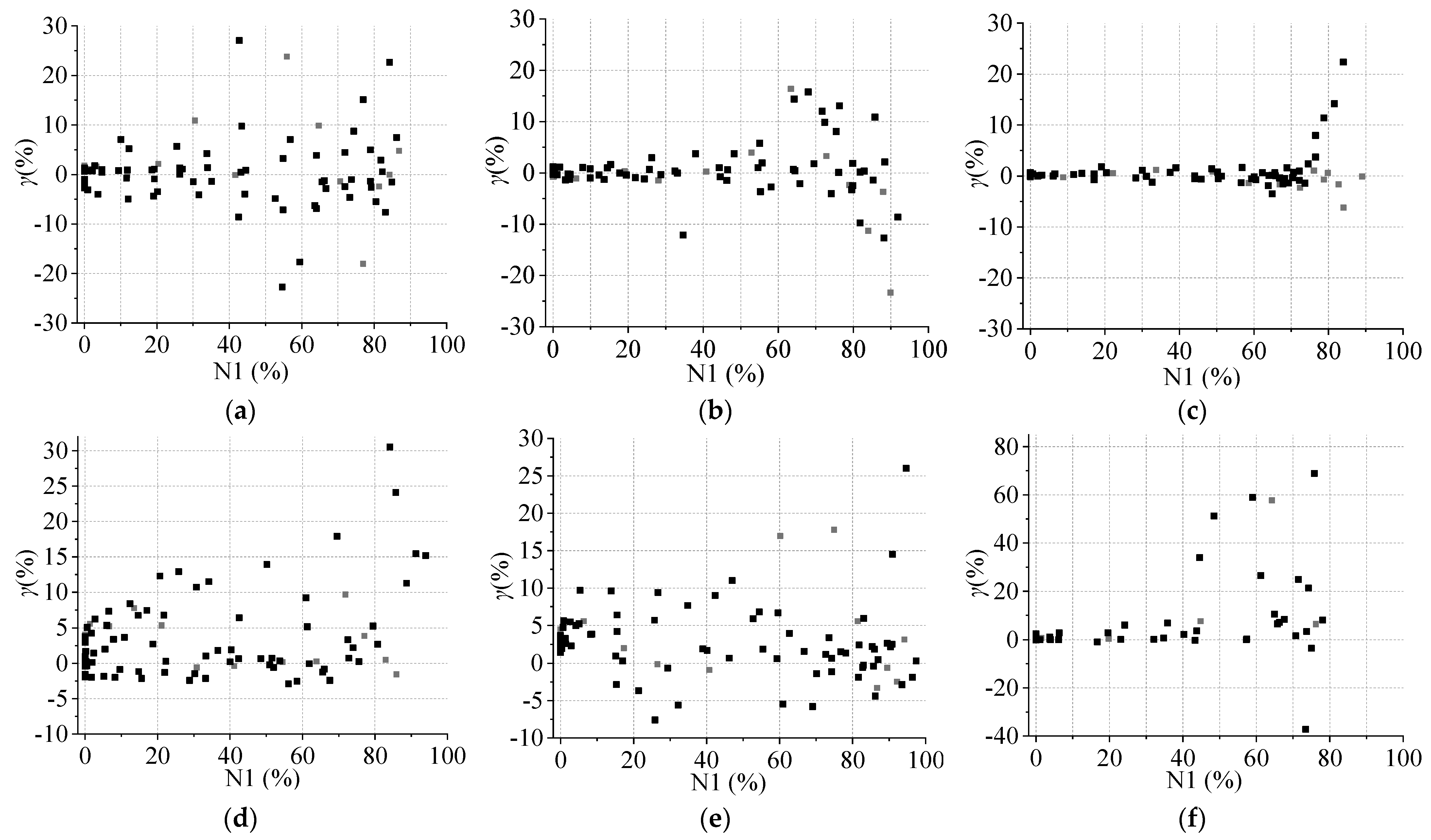
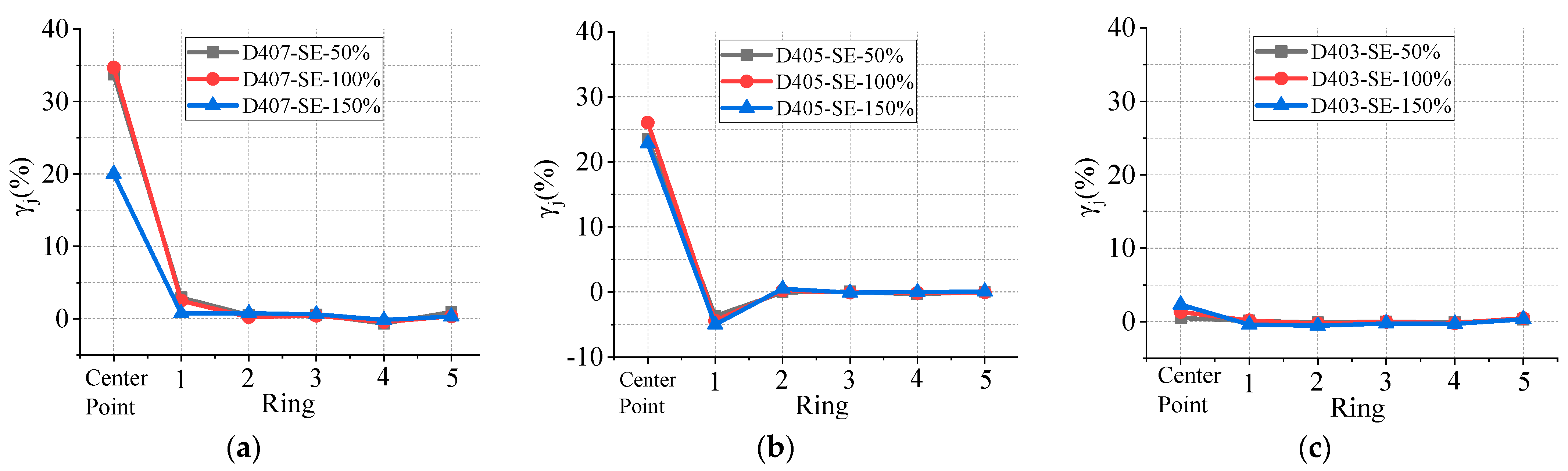
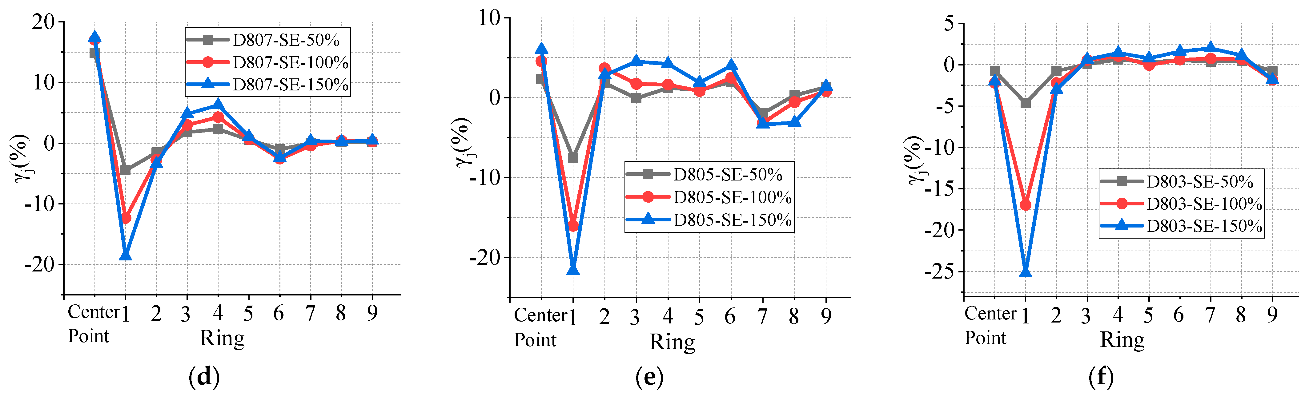
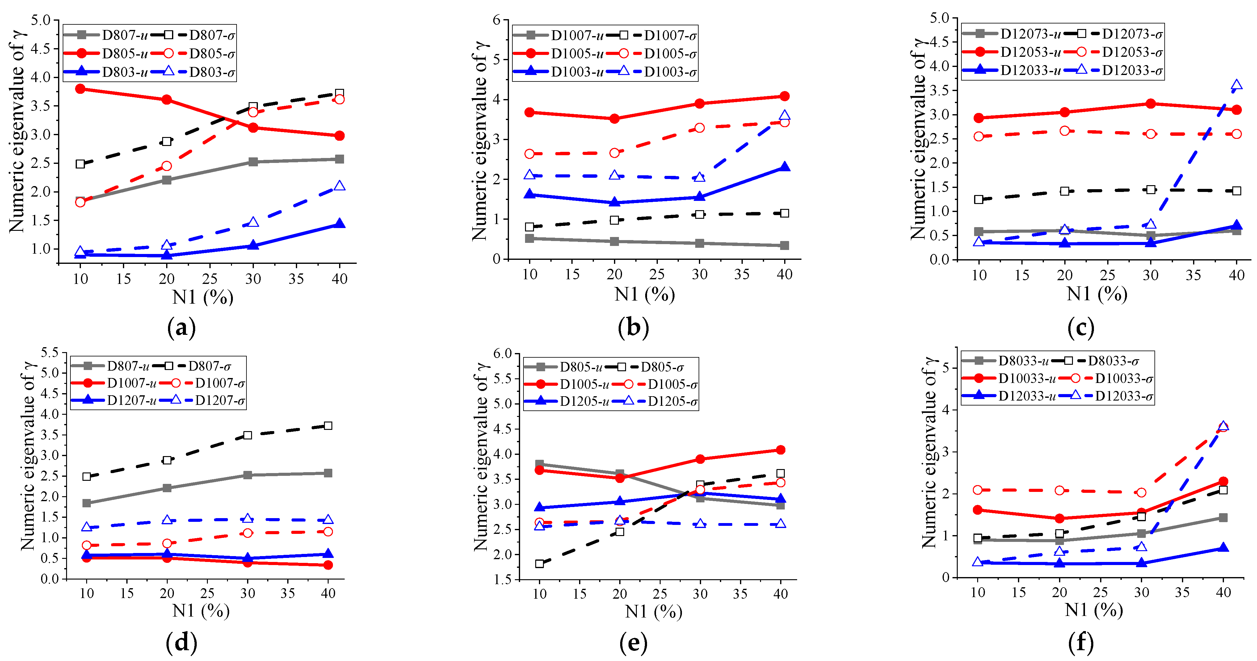
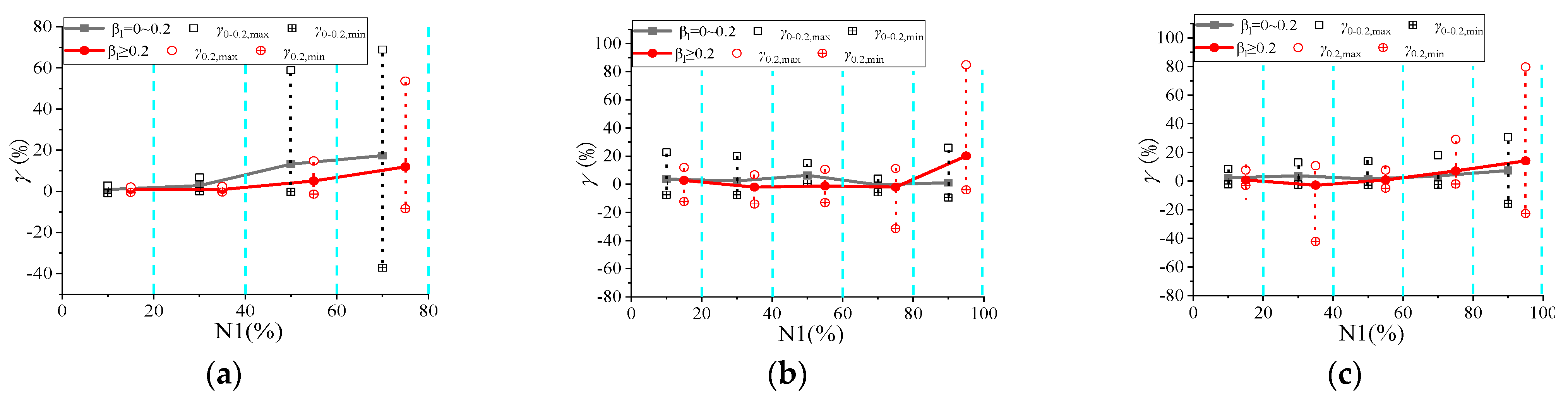
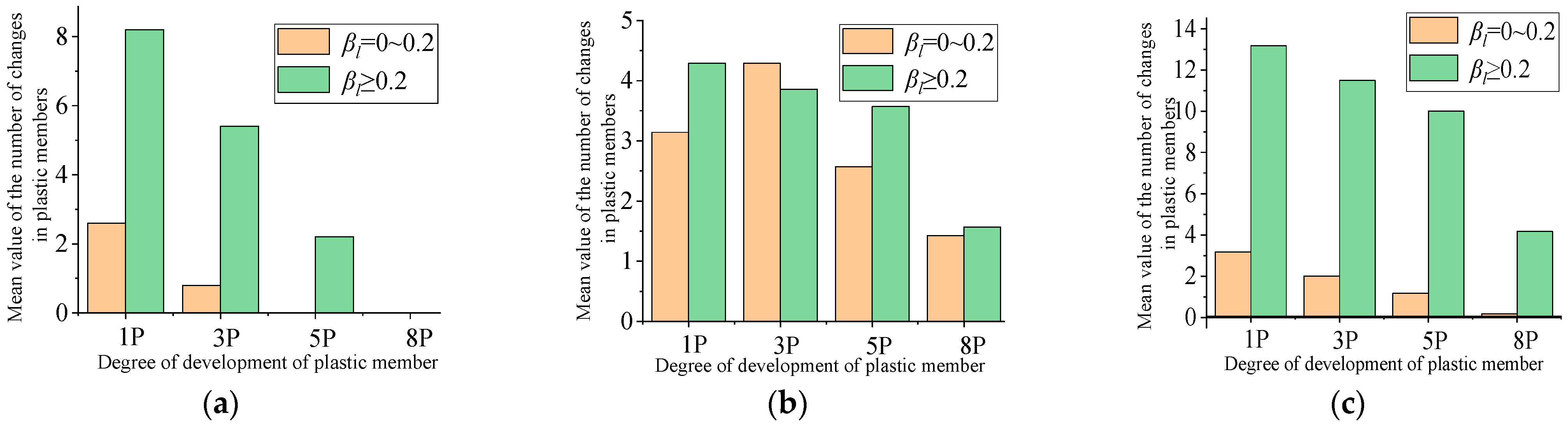
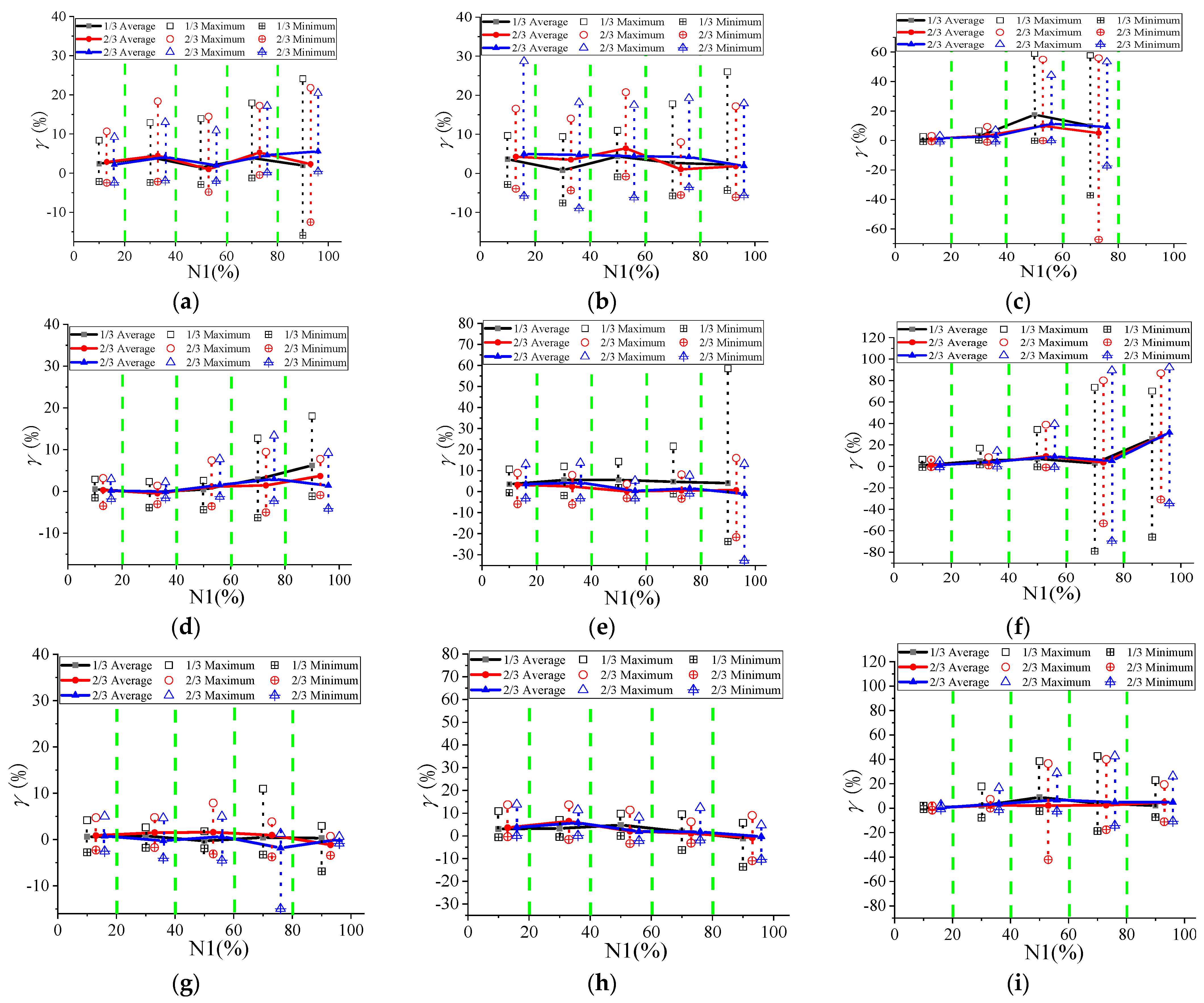
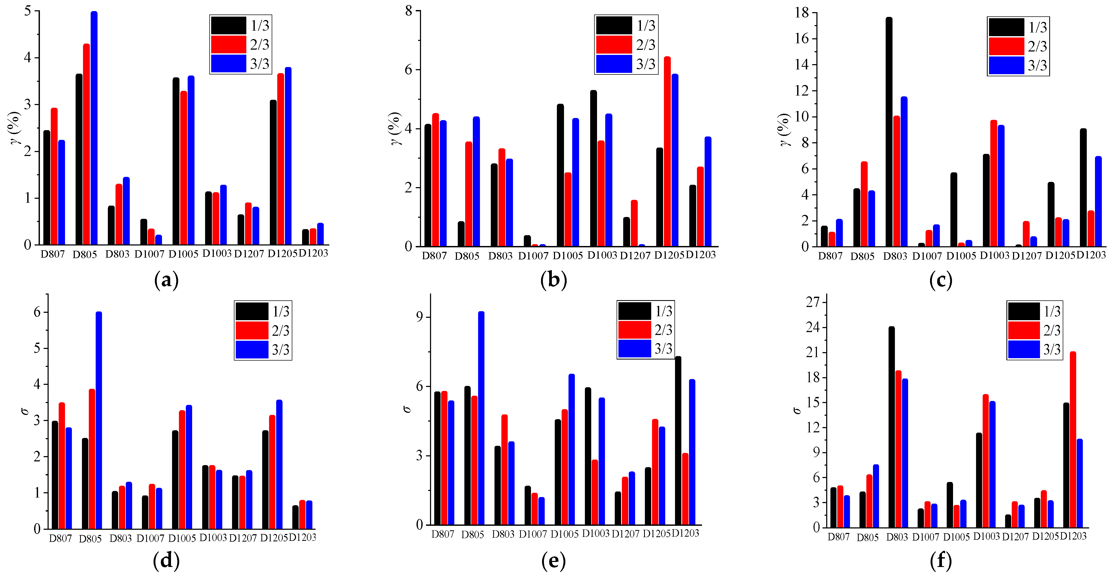
3.2.1. Influence of Spans and Rise-to-Span Ratios

In this section, the analysis of the influence of suspended equipment on the seismic response of reticulated shell structures with different spans (80 m, 100 m, and 120 m) and rise-to-span ratios (1/3, 1/5, and 1/7) will be carried out, where seven ground motions (GM1-GM7, as shown in Table 2) are applied to the reticulated shell structures.
As shown in Figure 10, the seismic influence coefficient γ of suspended equipment on reticulated shell structures with different spans and rise-to-span ratios show fluctuating changes as the proportion of plastic shell members increases. When the proportion of plastic members is larger (N1 > 40%), the discreteness of the seismic influence coefficients of all reticulated shell structures tends to increase. This trend is most significant in the reticulated shell structures with 1/3 rise-to-span ratio, indicating that the suspended equipment will exacerbate the uncertainty of the seismic performance of the reticulated shell structure with 1/3 rise-to-span ratio.
When the plastic development degree of the reticulated shell structure is shallow (N1 ≤ 40%), the seismic influence coefficient (γ) of the suspended equipment on the reticulated shell structures follows a normal distribution. The relationship between the numeric eigenvalues of the seismic influence coefficient (γ) and the proportion of plastic shell members (N1) are shown in Figure 11. Figure 11a–c show that the influence of suspended equipment on the reticulated shell structures mainly manifest as a vibration reduction effect, in which the effect of suspended equipment on the reticulated shell structures with a 1/5 rise-to-span ratio is the most obvious.
The span, rise-to-span ratio factors, and different degree of plastic development of the whole structure have a coupling effect on each other, and this comprehensive effect should be taken into consideration. As shown in Figure 11d–f, for the 1/7 rise-to-span ratio and larger-span (100 m and 120 m) reticulated shell structures, when the proportion of plastic shell members is less than 40%, the influence of the suspended equipment is very small. For the 1/5 rise-to-span ratio reticulated shell structure, when the N1 degree of plasticity of the reticulated shell structure is less than 20%, the influence of the suspended equipment on the reticulated shell structure decreases with the increase of span. For the 1/3 rise-to-span ratio reticulated shell structure, when the proportion of N1 is close to 40%, the dispersion of the value of γ tends to increase significantly with the increase of span of the reticulated shell structure, which indicates that the influence of the suspended equipment on the seismic performance of the 1/3 rise-to-span ratio reticulated shell structure with larger spans tends to be more unstable.

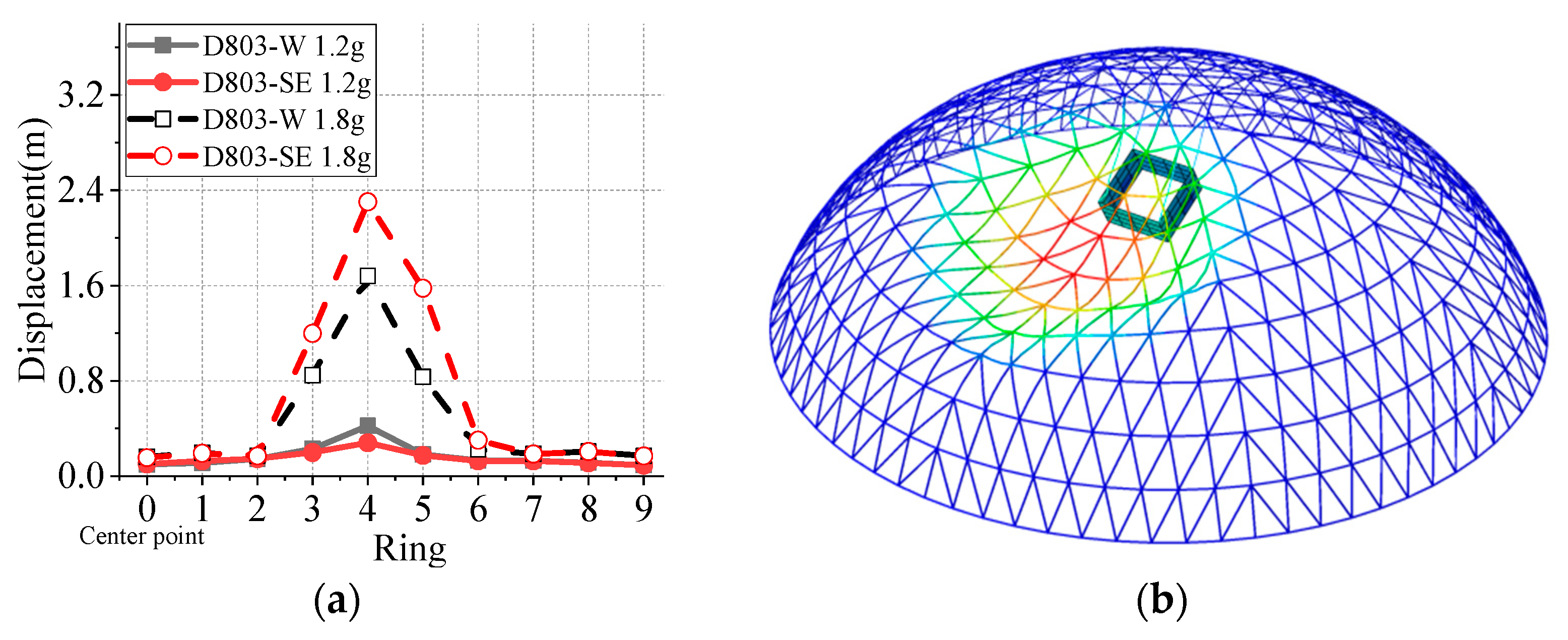
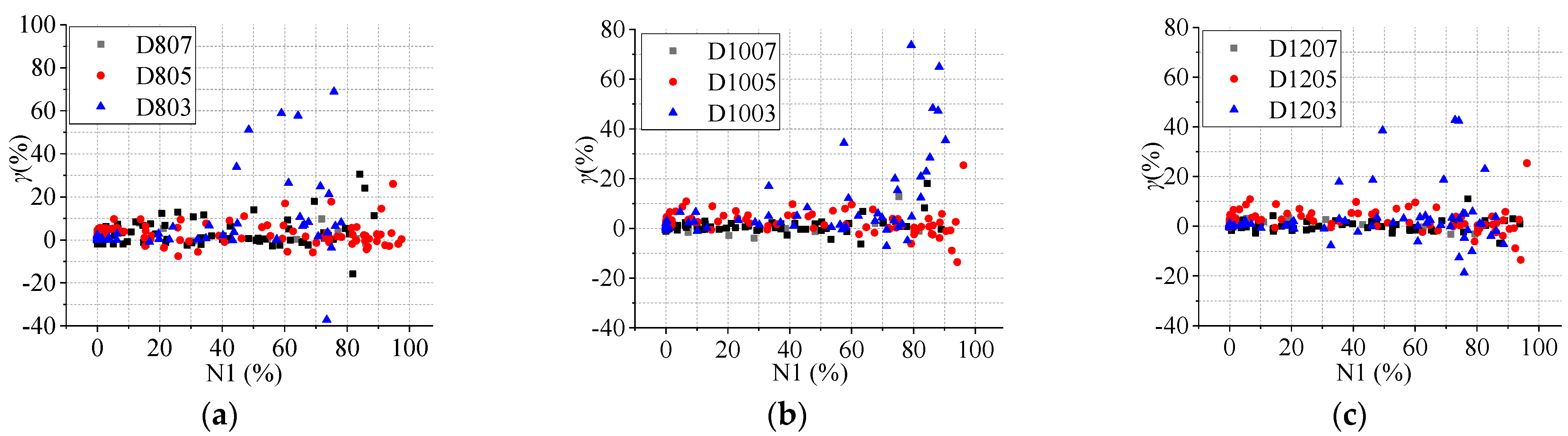
3.2.2. Influence of Different Ground Motions

This paper applies 7 ordinary ground motions (GM1-GM7) and 7 longer-period ground motions (GM8-GM14) to the reticulated shell structures with three different rise-to-span ratios, and compares the seismic influence coefficients of suspended equipment on the reticulated shell structures under different ground motions.
The influences of suspended equipment on the seismic performance of reticulated shell structures varies under different ground motions, different rise-to-span ratios, and the different degree of plastic development of the shell, the coupling effect of various factors needs to be considered. As shown in Figure 12a, under two types of ground motion, the vibration reduction influence of the suspended equipment on the reticulated shell structures with 1/3 rise-to-span ratio are similar. This is because the horizontal stiffness of the reticulated shell structures with larger rise-to-span ratio is relatively weak. Under two types of ground motion, the plastic shell members are mainly distributed in the area near the supports, and with the increase of seismic acceleration amplitude, the position of maximum node displacement gradually develops into a full section member yield area. The premature collapse of the structure leads to different types of ground motion having a smaller influence on the seismic performance of the reticulated shell structures with suspended equipment.
As shown in Figure 12b,c, under the action of longer-period ground motion, the influence of the suspended equipment on the reticulated shell structures with rise-to-span ratios of 1/7 and 1/5 are more significant. When the proportion of plastic members is larger (N1 > 60%), the fluctuation range of the seismic influence coefficient of suspended equipment is significantly increased. This is because under the action of longer-period seismic motion, the suspended equipment is more prone to significant oscillation. The suspended equipment has higher potential energy, and the larger the oscillation amplitude, the more significant influence on the redistribution of internal forces in the shell members, which leads to an increase in the fluctuation range of the influence of the suspended equipment on the seismic response of the reticulated shell structures.
On the other hand, the suspended equipment with steel cables has a significant impact on the mounting node displacement and the distribution of plastic shell members around mounting nodes. As shown in Figure 13a–c, under longer-period ground motion (GM8-GM-14), the suspended equipment causes the proportion of 1P and 8P plastic shell members in the first ring node area of the reticulated shell structure to be significantly higher than that under ordinary ground motions (GM1-GM-7). Based on the above analysis, it is found that longer periods ground motions are more likely to cause local damage to the area near the mounting nodes of the reticulated shell structures with suspended equipment and can even change the failure mode under strong earthquake.

3.2.3. Influence of Length of Steel Cable

The length of the steel cable is an important factor that affects the seismic response of a reticulated shell structure with suspended equipment. The length of the steel cable is selected as 1/3, 2/3, and 3/3 times the height of the reticulated shell structure, with spans of 80 m, 100 m, and 120 m respectively. The rise span ratio is selected as 1/7, 1/5, and 1/3, respectively, and seven ordinary ground motions (GM1-GM7) are selected from Table 2 for loading.
As shown in Figure 14, the influence of suspended equipment with different steel cable lengths on the seismic response of the reticulated shell structure shows fluctuating changes, and as the plastic deformation of the structure intensifies, the influence range of suspended equipment tends to increase. The length of steel cables, spans, rise-to-span ratios, and different degrees of plastic development of the shell all affect the seismic response of reticulated shell structures with suspended equipment, and the coupling effect of the above factors needs to be considered. In this section, the influence of different steel cable lengths are analysed according to three stages of proportion of plastic shell members (N1 is between 0–20%, 20~40%, and 40~60%, respectively) in reticulated shell structures with different spans and rise-to-span ratios. In these three stages, the seismic influence coefficients (γ) of suspended equipment with different steel cable lengths on the reticulated shell structure follow a normal distribution; the numeric eigenvalues of γ are shown in Figure 15.
As shown in Figure 15a, when N1 is less than 20%, the influence of different steel cable lengths on the values of γ is not obvious, and the maximum difference in the mean value of γ is not more than 1.5%. Figure 15d shows that, for the reticulated shell structures with 1/5 rise-to-span ratio, with the increase in the length of the steel cable, the dispersion of values of γ increase.
As shown in Figure 15b,e, when N1 is in the range of 20% to 40%, the maximum difference in the mean values of γ for the suspended equipment with different steel cable lengths is 3.6%, and the degree of dispersion of γ increases significantly.
As shown in Figure 15c,f, when N1 is in the range of 40% to 60%, the influence of the suspended equipment with three kinds of steel cable lengths on the 1/3 rise-to-span ratio reticulated shell structure is more significant, and the mean values and standard deviations of γ caused by different cable lengths on the 1/3 rise-to-span ratio reticulated shell structure have the largest difference, which indicates that the suspended equipment with different cable lengths will exacerbate the uncertainty of the seismic response of the 1/3 rise-to-span ratio reticulated shell structure.

4. Conclusions

This paper analyses the seismic response of the Kiewitt K-8 single layer spherical reticulated shell structure with suspended equipment, researches the influence mechanism of the suspended equipment on the strong seismic failure process of the reticulated shell structures, analyses the influence laws of the suspended equipment on the seismic response of different reticulated shell structures, and obtains the following conclusions.
(1) When the reticulated shell structure is in the elastic stage, the steel cable connection suspended equipment will significantly increase the seismic displacement response of the mounting node, but will reduce the maximum node displacement in other rings of reticulated shell structure, and this trend becomes more obvious with the increase of the mass of the suspended equipment. When the single steel pipe connects the suspended equipment and the centre node of the reticulated shell structures, the suspended equipment will reduce the displacement response of the mounting node, and the influence on the seismic displacement response of the nodes in other rings is small.
(2) Under the action of strong earthquakes, the suspended equipment affects the seismic response of the reticulated shell structures by changing the distribution of plastic shell members, and this paper summarises two typical strong earthquake failure modes of the reticulated shell structure with suspended equipment.
(3) Under the action of ordinary ground motions, when the degree of plasticity development of the reticulated shell structure is shallow (N1 ≤ 40%), the suspended equipment mainly shows a vibration reduction effect, in which the vibration reduction effect on the reticulated shell structures with 1/5 rise-to-span ratio is most obvious. With the deepening of the plasticity of the reticulated shell structure, the seismic influence coefficient of the suspended equipment fluctuates, in which the fluctuation of the seismic influence coefficient of suspended equipment in the reticulated shell structure with 1/3 rise-to-span ratio is the most drastic.
(4) Under the action of longer-period ground motions, the suspended equipment is more likely to cause local damage to the reticulated shell structure and even change the failure mode of the structure.
(5) Under the action of ordinary ground motions, when the degree of plasticity development N1 of the reticulated shell structure is smaller than 20%, the dispersion of the seismic influence coefficient of the suspended equipment on the reticulated shell structures with 1/5 rise-to-span ratio increases with the increase of the length of the steel cables. When the degree of plasticity development of the reticulated shell structure is deeper (N1 ≥ 40%), the influence of the suspended equipment with different lengths of the steel cables on the seismic response of the reticulated shell structures with 1/3 rise-to-span ratio is the most violent fluctuation, and the suspended equipment exacerbates the seismic response uncertainty of the reticulated shell structures with 1/3 rise-to-span ratio.

Author Contributions

Conceptualization, W.L and X.Z.; Methodology, W.L and X.Z.; Software, W.L and X.Z.; Validation, W.L.; Formal Analysis, W.L and X.Z.; Investigation, W.L.; Resources, W.L.; Data Curation, W.L.; Writing-Original Draft Preparation, W.L. and X.Z.; Writing-Review and Editing, W.L. and X.Z.; Visualization, W.L.; Supervision, X.Z.; Project Administration, W.L.; Funding Acquisition, W.L. All authors have read and agreed to the published version of the manuscript.

Funding

This study was supported by the Jilin Provincial Department of Education Science and Technology Research Project (JJKH20230142KJ), Northeast Electric Power University Doctoral Research Initiation Fund (BSJXM-2022221). The authors extend their sincere gratitude for the support.

Data Availability Statement

The original contributions presented in the study are included in the article, further inquiries can be directed to the authors.

Conflicts of Interest

The authors declare no conflict of interest.

References

  1. Cai, X.; Yu, H.; Nan, C. Discussion on Design of Center-hung Scoreboard System for Large Arena. Electr. Technol. Intell. Build. 2018, 12, 92–98. [Google Scholar]
  2. Qin, Q.; Li, Y. Design floor spectra for nonstructural components and equipment in buildings. J. Tsinghua Univ. 1997, 37, 22–29. [Google Scholar]
  3. Wang, X.; Liu, H.; Ou, J. Analysis of seismic response and catastrophic behavior of suspended structure systems. J. Earthq. Eng. Eng. Vib. 2009, 29, 121–125. [Google Scholar]
  4. Wang, C.; Lu, Z.; Wu, J. Seismic response of semi-flexible suspension vibration-absorption structures. J. Build. Struct. 2008, 29, 107–112. [Google Scholar]
  5. Wang, Z.; Hao, H. Optimization design and model tests for a pendulum eddy-current tuned mass damper. J. Vib. Shock. 2017, 37, 1–7. [Google Scholar]
  6. Fernando, S.O.; Suzana, A.; José, L.V.B. Design Criteria for A Pendulum Absorber to Control High Building Vibrations. In Proceedings of the 11th International Conference on Vibration Problems, Lisbon, Portugal, 9–12 September 2013; pp. 1–10. [Google Scholar]
  7. Zheng, G. Parameter Optimization of Multi-TMDs for Wind Excited Vibration Suppression of Tall Buildings. Adv. Build. Technol. 2002, 2, 1025–1032. [Google Scholar]
  8. Ye, J.; Chen, Y. Optimum Design for Reticulated Shell Structure TMD Systems Subjected to Seismic Excitations. J. Vib. Eng. 2000, 13, 376–384. [Google Scholar]
  9. Ye, J.; Chen, Y.; Shen, S. The present situation of seismic vibration control of reticulated shell structures using TMD system. J. Harbin Univ. CE Archit. 2000, 33, 10–14. [Google Scholar]
  10. Hu, J.; Huang, J.; Li, C. TMD Control Analysis for reticulated shell for wind vibration. J. Build. Struct. 2001, 2, 31–35. [Google Scholar]
  11. Liu, R.; Ji, C.; Li, X.; Wang, C.; Wang, G. On the seismic performance of the single-layer reticulated shell with a center-hung scoreboard under multiple seismic excitations. Shock. Vib. 2023, 2023, 3366063. [Google Scholar] [CrossRef]
  12. Xu, J.; Liu, R.; Ji, C.; Wang, C.; Wang, G. Effect of the CHS on Seismic Responses of the Single-Layer Spherical Reticulated Shell under Vertical Seismic Motions. Adv. Civ. Eng. 2023, 2023, 6720684. [Google Scholar] [CrossRef]
  13. Xue, S.; Zhao, Z.; Li, X.; Liu, R.; Dezhkam, M.; Lu, Z.; Liu, T.; Fan, Q.; Jing, H. Shaking table test research on the infuence of center-hung scoreboard on natural vibration characteristics and seismic response of suspen-dome structures. Buildings 2022, 12, 1231. [Google Scholar] [CrossRef]
  14. Xue, S.; Lu, Z.; Li, X.; Liu, R.; Zhao, Z.; Jing, H.; Fan, Q.; Liu, T.; Dezhkam, M. Experimental and numerical investigations on the infuence of center-hung scoreboard on dynamic characteristics of suspend-dome structure. J. Build. Eng. 2022, 57, 104787. [Google Scholar] [CrossRef]
  15. Ministry of Housing and Urban-Rural Development of the People’s Republic of China. Technical Specification for Space Frame Structures; China Planning Press: Beijing, China, 2010. [Google Scholar]
  16. Ministry of housing and urban rural development of the People Republic of China. Design Code for Sport Building (JGJ 31-2003); China Construction Industry Press: Beijing, China, 2003. [Google Scholar]
  17. Ministry of housing and urban rural development of the People Republic of China. Requirements and Test Method for LED Display in Sport Venues; China Construction Industry Press: Beijing, China, 2013. [Google Scholar]
  18. Zhang, Y.; Xue, S.; Yang, Q.; Fan, F. Large Span Space Structures; China Machine Press: Beijing, China, 2014. [Google Scholar]
  19. Zhi, X. Influence of initial geometric imperfection on static stability of single-layer reticulated shell structure. Spat. Struct. 2021, 27, 9–15. [Google Scholar]
  20. Fan, F.; Zhi, X. Failure Mechanism of Reticulated Shells under Earthquake; Science Press: Beijing, China, 2014. [Google Scholar]
  21. Li, W.; Zhi, X.; Fan, F. Influence of a Roofing System on the Seismic Performance of Single-Layer Spherical Reticulated Shell Structures. Buildings 2022, 12, 155. [Google Scholar] [CrossRef]
  22. Fan, F.; Zhi, X.; Li, W. Analysis of the Acceleration Response Spectrum in Single-Layer Spherical Reticulated Shell Structures. Appl. Sci. 2022, 12, 2116. [Google Scholar] [CrossRef]
  23. Li, X.; Wang, W.; Wu, D.; Xu, X.L.; Li, Z.J. Study on Characteristics Analysis and definition method of long period ground motion. J. Vib. Shock. 2014, 27, 685–692. [Google Scholar]
Figure 1. Single-layer spherical reticulated shell structures with suspended equipment. (a) The shell with single-node steel pipe connection; (b) the shell with steel cable connection; (c) the initial defect mode of the model (the defect amplitude is L/30 in Figure 1c).
Buildings 14 01706 g001
Figure 2. Different degrees of plasticity in the cross-section of the shell members. (a) 1P; (b) 3P; (c) 5P; (d) 8P.
Buildings 14 01706 g002
Figure 3. Seismic response of reticulated shell structures with suspended equipment. (a) Umax-PGA. (b) Proportion of the plastic shell members-PGA. (c) γ-N1 cures for D407 and D805.
Buildings 14 01706 g003
Figure 4. Comparison of plastic member distributions of reticulated shell structures. (a) D407-W 1.8 g. (b) D407-SE-1.8 g. (c) D805-W 1.6 g (d) D805-SE-1.6 g.
Buildings 14 01706 g004
Figure 5. γ-N1 cures of reticulated shell structures with suspended equipment. (a) D407-SE, (b) D405-SE, (c) D403-SE, (d) D807-SE, (e) D805-SE, (f) D803-SE.
Buildings 14 01706 g005
Figure 6. Influences of different mass suspended equipment on displacement response of reticulated shell structures. (a) D407. (b) D405. (c) D403. (d) D807. (e) D805. (f) D803.
Buildings 14 01706 g006aBuildings 14 01706 g006b
Figure 7. Seismic responses of ring nodes of reticulated shell structures with suspended equipment. (a) Maximum relative displacement of each ring nodes. (b) Deformation of D803-SE GM3-2 g (the loading time is the 19th second). (c) Changes in plastic shell members of each ring after adding suspended equipment at 1.2 g. (d) Changes in plastic shell members of each ring after adding suspended equipment at 1.8 g.
Buildings 14 01706 g007aBuildings 14 01706 g007b
Figure 8. Distributions and deformation of D803 plastic members of shells with suspended equipment. (a) D803-W GM3-1.2 g (b) D803-W GM3-1.8 g (c) D803-W GM3-2 g (d) D803-SE GM3-1.2 g (e) D803-SE GM3-1.8 g (f) D803-SE GM3-2 g.
Buildings 14 01706 g008aBuildings 14 01706 g008b
Figure 9. Comparisons of seismic responses of D8053 with suspended equipment. (a) Umax-PGA. (b) Proportion of the plastic shell member-PGA. (c) Plastic members distribution of D805-W under 2.2 g. (d) Plastic members distribution of D805-SE under 2.2 g. (e) Deformation of D805-SE under 2.4 g (the loading time is the 18th second).
Buildings 14 01706 g009
Figure 10. The γ-N1 in the shells with different spans and rise-to-span ratios. (a) 80 m span. (b) 100 m span. (c) 120 m span.
Buildings 14 01706 g010
Figure 11. The numeric eigenvalues of γ-N1 in the shells with different spans and rise to span ratios. (a) 80 m span. (b) 100 m span. (c) 120 m span. (d) 1/7 rise-to span ratio. (e) 1/5 rise-to span ratio. (f) 1/3 rise-to span ratio.
Buildings 14 01706 g011
Figure 12. The γ-N1 in the shells with different ground motion. (a) γ-N1 for D803. (b) γ-N1 for D805. (c) γ-N1 for D807.
Buildings 14 01706 g012
Figure 13. Mean values of the numbers of plastic shells members around mount node. (a) D803 0.6 g. (b) D805 1 g. (c) D807 2.2 g.
Buildings 14 01706 g013
Figure 14. γ-N1 data from reticulated shell structures with different length of suspended cable. (a) D807. (b) D805. (c) D803. (d) D1007. (e) D1005. (f) D1003. (g) D1207. (h) D1205. (i) D1203.
Buildings 14 01706 g014
Figure 15. The mean values and standard deviations of γ in the shells with different length of steel cables. (a) N1 ≤ 20% mean values. (b) 20% < N1 ≤ 40% mean values. (c) 40% < N1 ≤ 60% mean values. (d) N1 ≤ 20% standard deviations. (e) 20% < N1 ≤ 40% standard deviations. (f) 40% < N1 ≤ 60% standard deviations.
Buildings 14 01706 g015
Table 1. Different parameters of spherical reticulated shell structures with roofing systems.
NO.Span (m)Number of RingsRise-to-Span RatioRib/Ring Member (mm)Diagonal Member (mm)Total Number of the Shell MembersSuspended Equipment Weight (t)Connection Method
D4034061/3159 × 4.5159 × 4.54560.65Steel pipe
D4051/5140 × 4.5140 × 4.50.65
D4071/7140 × 6.0133 × 6.00.65
D80380101/3194 × 6.0194 × 6.012407.34Steel cable
D8051/5194 × 8.0194 × 8.05.5
D8071/7219 × 12219 × 125.07
D1003100121/3194 × 10194 × 1017767.95Steel cable
D10051/5203 × 16203 × 165.73
D10071/7219 × 8219 × 85.45
D1203120141/3219 × 12219 × 1224088.36Steel cable
D12051/5219 × 16219 × 166.32
D12071/7325 × 14325 × 145.78
D1205: D-reticulated shell structure; 120: the span is 120 m; 5: rise-to-span ratio is 1/5.
Table 2. Ground motions information.
NO.Event NameStation NameYearStation LocationMagnitudeβl
GM1San FernandoLA1971RSN686.610.14
GM2Imperial ValleyDelta1979RSN1696.530.15
GM3ParkfieldCholame1963RSN0136.190.04
GM4KOBEShin-Osaka1995RSN11166.90.07
GM5DuzceBolu1999RSN16027.140.03
GM6ImperialCompuertas1979RSN1676.530.03
GM7NorthridgeArleta1994RSN9496.690.05
GM8ChiChiTCU0831999RSN15167.10.21
GM9ChiChiTCU0081999RSN14667.10.38
GM10ChiChiTCU0071999RSN14657.60.27
GM11ChiChiTCU1031999RSN15307.60.24
GM12ChiChiTCU0391999RSN14827.10.6
GM13ChiChiTCU0521999RSN14927.10.5
GM14ChiChiTCU1281999RSN15487.10.58
Disclaimer/Publisher’s Note: The statements, opinions and data contained in all publications are solely those of the individual author(s) and contributor(s) and not of MDPI and/or the editor(s). MDPI and/or the editor(s) disclaim responsibility for any injury to people or property resulting from any ideas, methods, instructions or products referred to in the content.

