Abstract
The objective of this research is to investigate the characteristics of the deformation response in adjacent subway tunnels caused by deep foundation excavation of reclaimed land. Focusing on a deep foundation excavation project situated in proximity to Line 11 of the subway in Shenzhen, this study employs theoretical analysis, numerical simulation, and on-site measurements to thoroughly investigate the deformation issues induced by the unloading of the excavation. The research results are as follows: using the energy method to calculate the uneven deformation of adjacent subway tunnels caused by the excavation can overcome the limitations of traditional algorithms, which treat the subway tunnel as a uniformly elastic foundation beam, resulting in more reasonable calculation results. Increasing the self-stiffness (EI)eq of the tunnel can effectively reduce the maximum displacement (wmax) of the tunnel, and as (EI)eq increases, its “weakening effect” on wmax gradually diminishes. Underground continuous walls can effectively control tunnel deformation, with tunnel displacement decreasing as the thickness and concrete strength of the continuous walls increase. “Long excavation” deep foundation excavations can impact the displacement and uplift range of the tunnel, with the maximum tunnel displacement showing a nonlinear decrease with increasing excavation depth. Tunnel displacement decreases as geotechnical parameters (elastic modulus E, internal friction angle φ, and cohesion C) increase, with the elastic modulus being the most sensitive parameter. The research findings can be applied to tunnel construction, maintenance, and safety evaluations, providing valuable references for similar engineering projects in the future.
1. Introduction
With the expansion of urban construction and rapid growth in high-rise buildings and subway networks, deep foundation excavation projects have become significant endeavors. Among these projects, the impact of foundation pit construction on adjacent subway tunnels has become a focal point for urban underground engineering construction management. Excavation of foundation pits alters the stress and deformation fields of the soil, potentially leading to stress and displacement exceeding allowable values in subway structures, thus affecting the normal operation of the subway [1,2,3,4,5,6]. Therefore, accurately assessing and predicting the impact of foundation pit excavation on nearby subway tunnels is an urgent issue that needs to be addressed.
Theoretical analysis is an important method for studying the mechanical characteristics of deep foundation excavation processes. Wang et al. [7] studied the influence of clayey soil adhesion on the clogging of tunnel boring machines through experiments and proposed a new semi-empirical diagram, which found that the maximum adhesion occurred in the region of strong clogging, indicating the feasibility of using adhesion stress as an index to evaluate the clogging of tunnel boring machines. Fu et al. [8] derived analytical solutions for the quarter-space grouting of rigid support structures based on the original-original principle and cavity expansion theory, and validated tunnel horizontal displacements calculated using Paschenak foundation beam theory with engineering examples from Tianjin and Shenzhen. Zhang et al. [9] studied the distribution characteristics of soil pressure in limited spaces through the expansion project of a small space subway station in Shenzhen, and deeply investigated the mechanical properties of pile-supported structures using theoretical analysis and indoor tests. Zhang et al. [10] divided the influence area of sidewalls by considering the deformation of retaining structures and the spatial effect of foundation pit excavation, analyzed and calculated the additional stress generated, and further introduced a shield tunnel rotation and dislocation cooperative deformation model to study the longitudinal deformation of adjacent tunnels under multiple factors during foundation pit construction. Huang et al. [11] theoretically analyzed the inadequacy of current force input conditions and the reasonability of displacement input conditions, distinguished between two Winkler foundation moduli under different input conditions, and proposed to use passive and active Winkler foundation moduli for displacement and force input conditions, respectively, to obtain a more reasonable tunnel response to upper foundation pit excavation. Wei et al. [12] introduced a rotational and staggered deformation-coordinated shield tunnel model, derived a formula for calculating the longitudinal deformation of the lower shield tunnel caused by foundation pit excavation based on the image source method, and validated the calculation method by comparing B-W and B-P methods with three actual engineering monitoring data, and analyzed the four influencing factors, namely, maximum uplift of the pit bottom, excavation width, excavation depth, and tunnel burial depth.
In addition to theoretical analysis, numerical simulation and on-site measurements play important roles in studying the mechanical characteristics of deep foundation excavation projects. Niu et al. [13] conducted in-depth research on the deformation of adjacent subway tunnels caused by foundation pit excavation in the influence zone of a fault zone, using theoretical analysis, numerical simulation, and on-site measurements. Zhang et al. [10] analyzed the impact mechanism of foundation pit excavation on adjacent shield tunnels based on the theoretical change of lateral forces in adjacent shield tunnels caused by foundation pit excavation, and further calculated the additional stress generated in the soil and the longitudinal deformation of the tunnel. Wang et al. [14] established a Winkler foundation–Timoshenko beam model for longitudinal deformation analysis of adjacent station (working well) shield tunnels under foundation pit excavation unloading, and strictly derived the differential solution of the analytical model based on the force method principle. Wei et al. [15] used a small-strain hardening model of soil and a two-dimensional finite element numerical method to conduct numerical simulations on the deformation of adjacent existing shield tunnel segments caused by the excavation of a foundation pit in soft soil and analyzed the variation in tunnel segment vertical and horizontal displacements with different influencing factors using a single-factor analysis method and a multi-factor analysis method. Chen et al. [16] proposed a theoretical calculation method for lateral force in shield tunnels considering the influence of retaining structure deformation, verified the reliability of the theoretical calculation method through numerical simulation and centrifuge tests, and explored the correlation mechanism between tunnel lateral force, deformation, and internal force based on actual engineering site monitoring data. Liu et al. [17] used numerical methods to elucidate the impact of excavation of a foundation pit adjacent to an existing tunnel on the existing tunnel structure and compared the measured data with finite element data to verify the effectiveness of the adopted three-dimensional model. Feng et al. [18] simplified the tunnel into a Timoshenko beam that considers both longitudinal stiffness and shear deformation, used a three-parameter Kerr foundation model for the foundation, and obtained the analytical solution for longitudinal deformation of the tunnel using finite difference method while considering the boundary conditions at both ends of the tunnel. The rationality of this method was verified by comparing it with finite element data, existing foundation model theory, and measured engineering data. Wu et al. [19] studied the influence of deep foundation excavation of soft soil layers on the lower subway tunnel, conducted deformation monitoring of the lower subway tunnel during the deep foundation excavation of a bridge abutment foundation pit, and analyzed the influence of different construction conditions on the displacement and deformation of the subway tunnel through the analysis of accumulated settlement and horizontal displacement data. Zhao et al. [20] established a three-dimensional finite element model based on a typical case of foundation pit and tunnel, using various methods to determine the geomechanical properties such as standard penetration tests and heavy dynamic penetration. Zheng et al. [21] used a large-scale foundation pit project adjacent to a nearby subway structure as an example to analyze the deformation characteristics of subway structures during foundation pit construction and conducted experiments and practical applications to actively control the horizontal deformation of soil and tunnel by grouting. On this basis, they compared and evaluated several tunnel deformation control methods through numerical simulation and conducted optimization research on grouting schemes. Wei et al. [22] established a three-dimensional finite element model for foundation pit excavation above an existing shield tunnel arranged with anti-floating anchor rods, considered the length, diameter, angle, spacing, and number of pipe sections of the anti-floating anchor rods, and analyzed the influence of the arrangement scheme of the anti-floating anchor rods on the anti-floating effect of the shield tunnel, while considering the excavation conditions of the foundation pit and the relative position relationship with the shield tunnel, and analyzed the effect of the anti-floating anchor rods under different conditions. Wu et al. [23] conducted numerical simulations on the process of constructing a gantry anti-floating framework and the influence of large-scale foundation pit excavation on the lower shield tunnel, explored the interaction mechanism and anti-floating effect of the gantry anti-floating framework and the strata, and finally proposed optimized design suggestions for the anti-floating framework structure. Liu et al. [24] collected 42 engineering cases of foundation pit excavation affecting adjacent side tunnels, analyzed the influence of important factors on vertical and horizontal displacements of the tunnels, determined the discriminant conditions for uplift and subsidence of the tunnel, gave a zoning of vertical displacement of the tunnel outside the pit, and proposed a comprehensive predictive indicator for horizontal displacement of the tunnel and gave empirical predictive formulas for tunnel horizontal displacement under three different strata conditions. Based on the research results of different scholars, it can be observed that when studying the deformation characteristics of adjacent subway tunnels caused by foundation pit excavation, there are certain differences in the research results due to factors such as research methods and regional conditions. Therefore, it is necessary to use different research methods to conduct in-depth studies on specific engineering cases.
Based on the research analysis of the literature mentioned above, there is currently a wealth of studies on foundation pit engineering projects under complex geological conditions both domestically and internationally. However, research on foundation pit engineering specifically focused on reclaimed land is relatively scarce. Therefore, it is necessary to conduct research on the impact of deep foundation pit excavation of reclaimed land on the deformation of nearby subway tunnels. This study is based on a deep foundation pit project located near a subway tunnel in Shenzhen. The study employs theoretical analysis, numerical simulation, and on-site measurements to investigate the uneven deformation caused by foundation pit excavation in the adjacent subway tunnel. The energy method is used to calculate the uneven deformation of the adjacent subway tunnel caused by foundation pit excavation, resulting in more reasonable calculation results. The study also examines the influence of underground structure parameters, foundation pit excavation parameters, and geological parameters on tunnel deformation, and analyzes the sensitivity of geological parameters. The research findings have certain theoretical value and engineering significance, providing references for the design of deformation control schemes for adjacent subway tunnels in similar projects.
2. Project Overview
2.1. Project Introduction
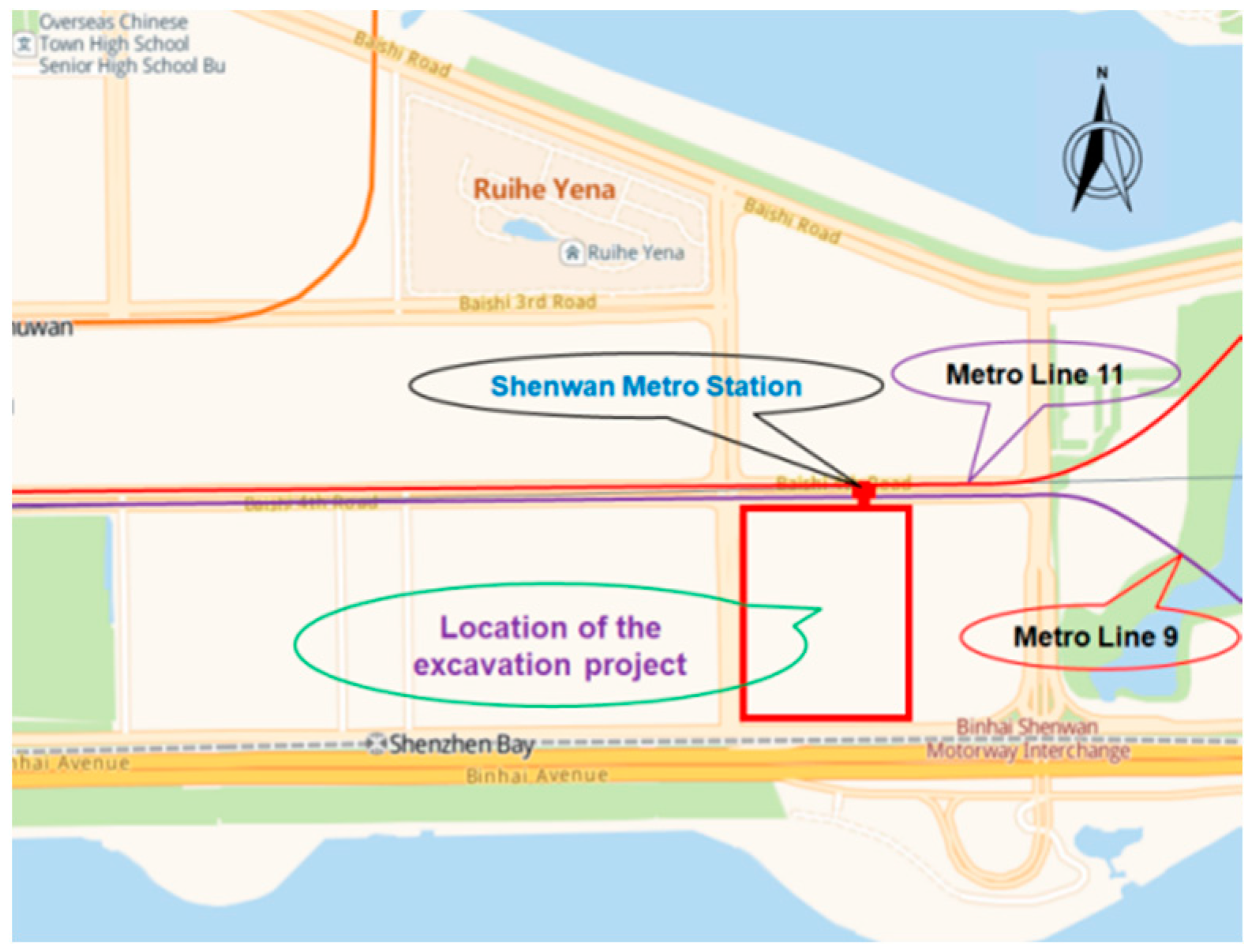
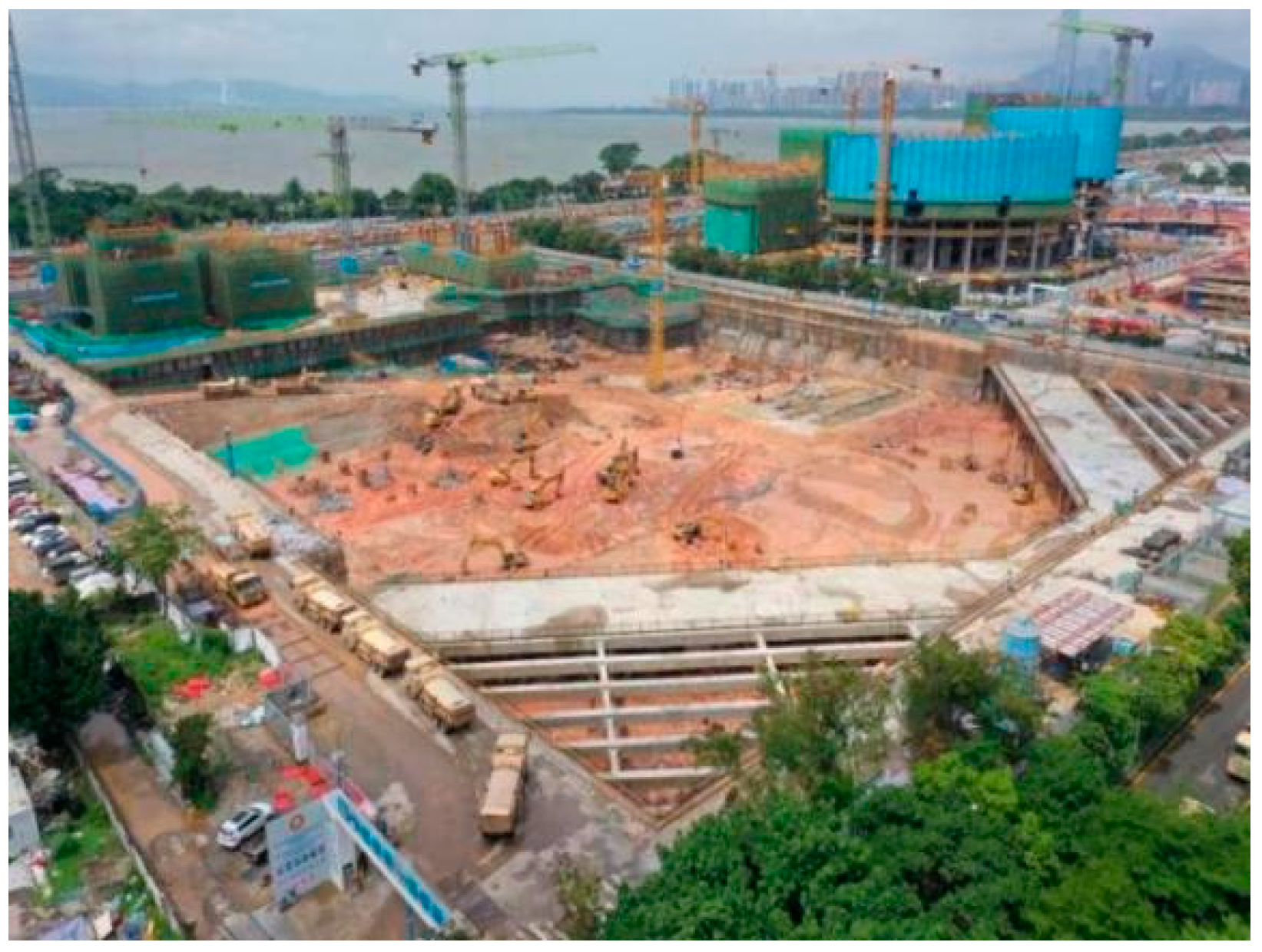
This paper is based on a project located near the Deep Bay Metro Station in the reclamation area of Shenzhen City. The surrounding area of the foundation pit covers approximately 10,670 m2 and is within the protected zone (50 m) of Shenzhen Metro Line 9 and Line 11. The foundation pit is located about 5 m away from the closest structure of Metro Line 9 station and approximately 10.5 m away from the outer boundary of Metro Line 11 tunnel structure. The elevation of the nearby tunnel top is approximately −17.4 m. The outer diameter of the tunnel is 6.7 m, and the thickness of the concrete lining segments is 350 mm with a concrete strength of C35. The plan view of the foundation pit–tunnel layout and aerial photograph of the site are shown in Figure 1, Figure 2 and Figure 3. The parameters of the supporting structure are presented in Table 1.

Figure 1.
Plan view of foundation pit and tunnel location.

Figure 2.
Aerial photograph of the site.
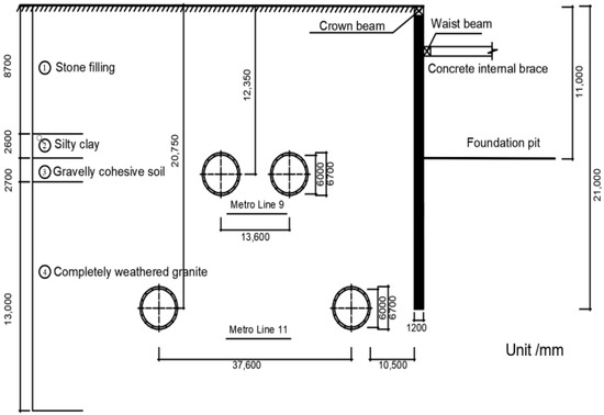
Figure 3.
Foundation pit–tunnel cross-section.

Table 1.
The cross-sectional dimensions and physical–mechanical properties of the support structure.
2.2. Geotechnical Conditions of the Project
The simplified stratigraphy of the site from top to bottom is as follows: ① stone filling layer; ② silty clay layer; ③ gravelly cohesive soil layer; ④ completely weathered granite layer; ⑤ highly weathered granite layer; ⑥ moderately weathered granite layer; ⑦ slightly weathered granite layer, which remains unexposed. The relevant parameters of the strata were obtained from triaxial consolidation drainage tests, triaxial loading–unloading tests, standard curing tests, and resonance column tests. In consideration of the foundation pit excavation as a stress-release process, the rebound modulus of the soil is three times the deformation modulus. The main geotechnical and physical parameters of the site are shown in Table 2.
Table 2.
Main physical and mechanical parameters of rock–soil.
3. Theoretical Calculation and Analysis of Tunnel Displacement
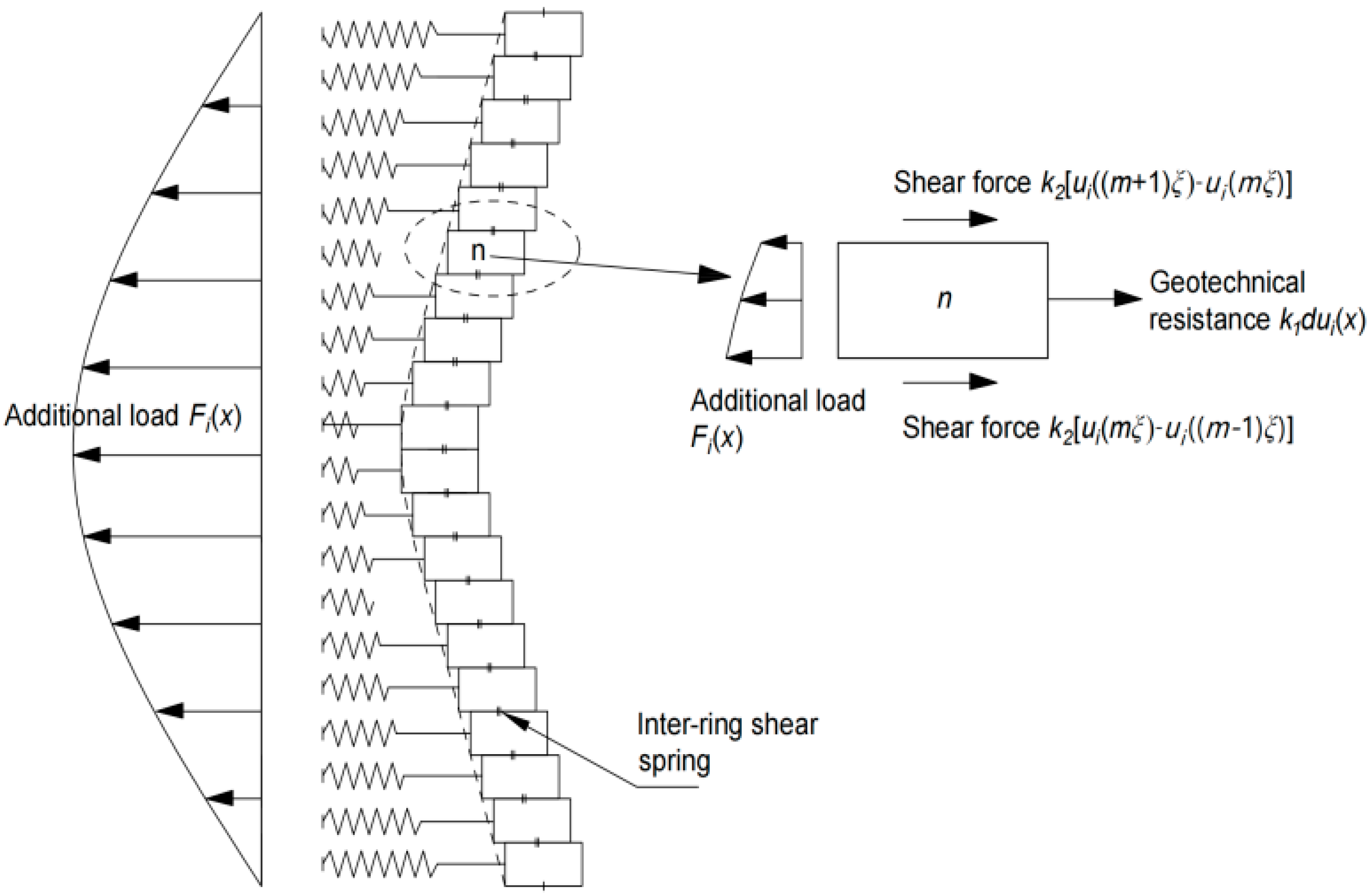
The subway tunnel exhibits inhomogeneous deformation, whereas the traditional algorithm, which assumes it to be a mean-averaged elastic foundation beam, exhibits homogeneous deformation. This is an idealized assumption that leads to errors in the calculation results. Considering the inadequacy of treating the subway tunnel as an average elastic foundation beam in traditional algorithms, the energy method (Zhou et al. [25]) is adopted for a more rational calculation of the uneven deformation of the adjacent subway tunnel caused by foundation pit excavation. Assuming that the tunnel structure is composed of a series of shear springs connected to an elastic foundation short beam, the deformation of the tunnel lining due to the excavation of the foundation pit is considered; thus, a longitudinal deformation calculation model of the tunnel is established, as shown in Figure 4. The force analysis is performed on the nth ring with a ring width of ξ.
where Fi(x) represents the additional load acting on the tunnel; d is the outer diameter of the tunnel; σi(x) is the additional stress acting on the tunnel (the specific solution can be found in a study by Niu et al. [13]); i represents horizontal and vertical directions; k1 and k2 are foundation bed coefficients and shear stiffness between rings, respectively; and u represents the tunnel displacement.
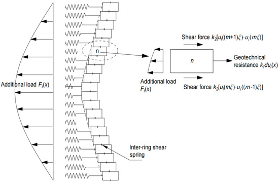
Figure 4.
Tunnel deformation calculation model.
The work carried out by the additional load on the tunnel, W1, can be expressed as:
The work performed by the shear force between tunnel rings, W2, is given by:
The work carried out by the resistance of the strata, W3, is expressed as:
By combining Equations (2)–(4), the total potential energy, Ei, of the adjacent tunnel caused by the excavation of the foundation pit can be obtained as:
By using the Ritz method (), the vertical and horizontal displacements, ui(x), of the adjacent subway tunnel caused by foundation pit excavation can be determined.
4. Finite Element Numerical Simulation Analysis
4.1. Three-Dimensional Finite Element Analysis Model
MIDAS GTS NX three-dimensional finite element software (version 2019) was used to simulate the design conditions and study the deformation effects of the surrounding environment during the excavation and support process of the foundation pit. According to the Saint-Venant’s principle, the influence range of the foundation pit excavation on the surrounding environment is approximately three to five times the excavation depth. Therefore, the three-dimensional numerical model’s dimensions were chosen as 400 m × 450 m × 40.5 m. The three-dimensional finite element model is shown in Figure 5.
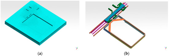
Figure 5.
Three-dimensional finite element analysis model. (a) Three-dimensional finite element model; (b) relationship between tunnel supporting structure and tunnel.
The waist beams and support elements of the foundation pit support were represented using one-dimensional beam elements, with their cross-sectional shapes and dimensions identical to the actual structures. The foundation pit support piles were replaced by equivalent stiffness and represented using two-dimensional plate elements. The support anchors were represented using one-dimensional implanted truss elements. The station lining structure and tunnels were represented using two-dimensional plate elements, with their cross-sectional dimensions matching the actual structures. In the geotechnical finite element analysis, one-dimensional elastic rod elements were used to simulate the internal supports in the foundation pit, while plain plate elements were used to simulate the foundation pit retaining walls, floor supports, tunnel linings, and channel structures. All soil layers were assumed to be elastic-plastic materials, and the Mohr–Coulomb criterion was used as the failure criterion, with the constitutive model selected as the Modified Mohr–Coulomb model. A mixed mesh generator was used to generate the mesh for the rock–soil materials, resulting in a total of 33,020 nodes and 190,960 elements. The material parameters are detailed in Table 2.
4.2. Boundary Conditions and Loads
In the calculation model, the vertical boundary conditions were constrained by horizontal hinge supports, and the base of the model was constrained in the vertical direction. The boundary conditions were kept constant during each calculation construction stage. The initial vertical stress field at the site was set as the self-weight of the soil, and the horizontal stress σx was determined according to the following equation:
where K0 represents the coefficient of static earth pressure, with values of 0.35 for completely weathered rock, 0.18 for highly weathered rock, and 0.1 for moderately weathered rock, calculated using the following equation for other soils:
4.3. Construction Conditions Setting
The construction condition setting is shown in Table 3.
Table 3.
Setting of construction conditions.
4.4. Calculation Results and Analysis
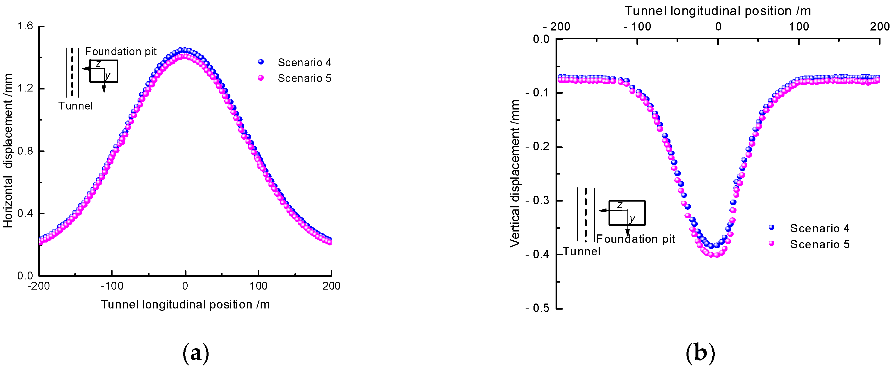
The horizontal and vertical displacement numerical results were extracted from the mid-axis of the right bottom surface of the tunnel structure and plotted in Figure 6. During the excavation of the foundation pit, the horizontal displacement of the mid-axis of the tunnel sidewall is shown in Figure 6a. As the excavation depth of the foundation pit increases, the horizontal displacement gradually increases. Especially within the range of the foundation pit excavation (−90 m to 90 m), the tunnel is significantly affected, and there is clear correspondence between the overall lateral displacement deformation region of the tunnel and the range of the foundation pit excavation. Within the foundation pit excavation range, the tunnel exhibits larger horizontal displacements, noticeably exceeding the horizontal displacements generated by the tunnel sections outside the excavation range. As the distance from the foundation pit excavation range increases, the horizontal displacement of the tunnel gradually decreases. The horizontal displacement curve shows that the model is symmetrical, with a maximum horizontal displacement of 1.4 mm, indicating small deformations.

Figure 6.
Displacement and deformation curve of up-line tunnel. (a) Horizontal displacement; (b) vertical displacement.
The variation in vertical displacement along the mid-axis of the right bottom surface of the tunnel structure is shown in Figure 6b. It can be observed that throughout the excavation process, the settlement of the bottom of the tunnel on both sides increases with the increasing depth of the foundation pit excavation. Similarly, within the foundation pit excavation range, the settlement of the tunnel significantly increases. Within the foundation pit excavation range, the settlement is greater than the settlement generated by the tunnel sections outside the excavation range. As the distance from the excavation range increases, the settlement of the tunnel gradually decreases.
4.5. Comparison and Analysis of Monitoring Results
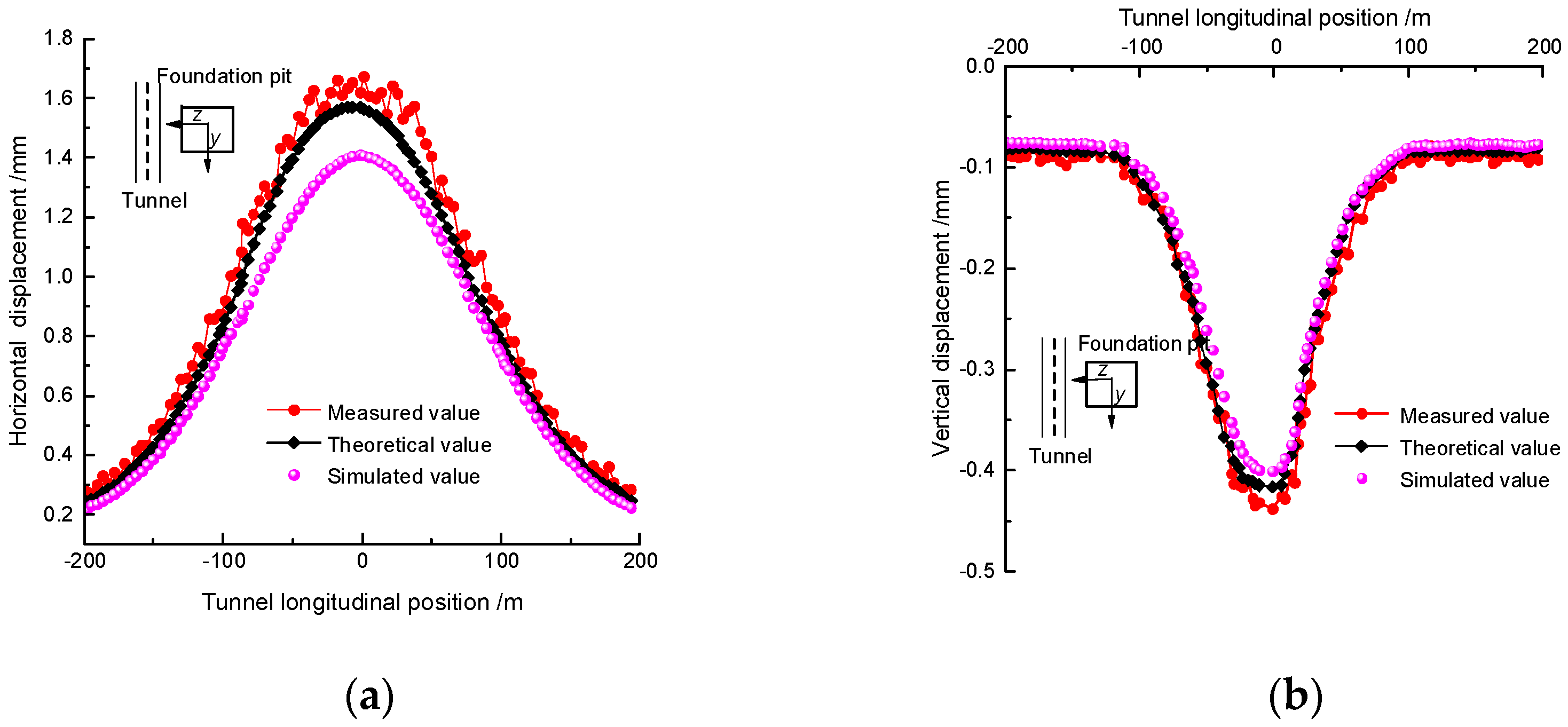
The comparison and analysis of theoretical, simulated, and monitored horizontal and vertical displacements of the tunnel are shown in Figure 7. The influence law of pit excavation on horizontal displacement and vertical displacement of adjacent subway tunnels basically conforms to the normal distribution law. Considering factors such as the overall excavation of the foundation pit, delayed support reinforcement, and surface loading, the monitored horizontal displacement of the tunnel is noticeably larger than the theoretical and simulated values. Similarly, the numerical simulation of the foundation pit excavation did not consider the coupled effect of seepage, resulting in larger vertical displacement values in the actual tunnel monitoring. Overall, the numerical results of the three methods show consistent trends, validating the feasibility of numerical calculations and the reliability of simulation results.

Figure 7.
Comparative analysis of monitoring results. (a) Horizontal displacement; (b) vertical displacement.
5. Influence Analysis of Structural Parameters
5.1. Impact of Tunnel Equivalent Flexural Stiffness
As shown in Figure 8, the relationship curve between the tunnel’s longitudinal equivalent flexural stiffness (EI)eq and the maximum displacement (wmax) under different equivalent flexural stiffness values is presented. As the equivalent flexural stiffness increases to 100, the reduction in wmax under the four working conditions is 47.7%, 46.7%, 45.0%, and 40.2%, respectively. It can be observed that increasing the tunnel’s own stiffness effectively reduces the maximum displacement (wmax). Simultaneously, with the gradual increase in the equivalent flexural stiffness (EI)eq, its weakening effect on wmax gradually diminishes. Furthermore, from Figure 8, it is evident that wmax follows a non-linear decreasing trend of “rapid decrease followed by a slow decrease” with the increasing equivalent flexural stiffness (EI)eq. This indicates that appropriately increasing (EI)eq can significantly improve wmax. However, excessively increasing (EI)eq may weaken the improvement effect on wmax. Therefore, it is necessary to pay attention to not excessively increasing (EI)eq while improving the stiffness to avoid compromising the improvement effect on wmax.
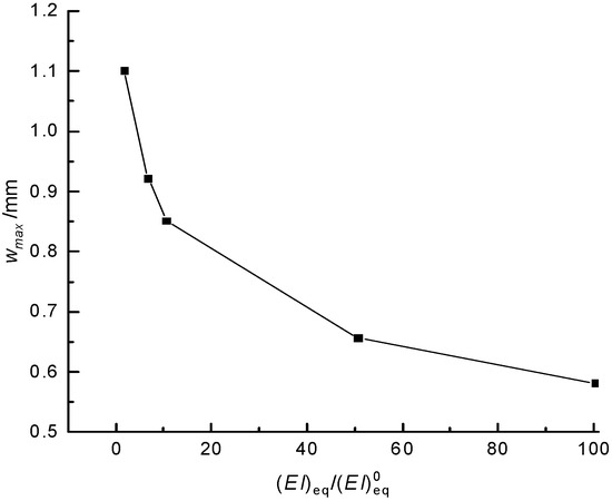
Figure 8.
Maximum displacement curve of tunnel under different equivalent bending stiffness.
5.2. Impact of Underground Continuous Wall Parameters
5.2.1. Influence of Wall Thickness
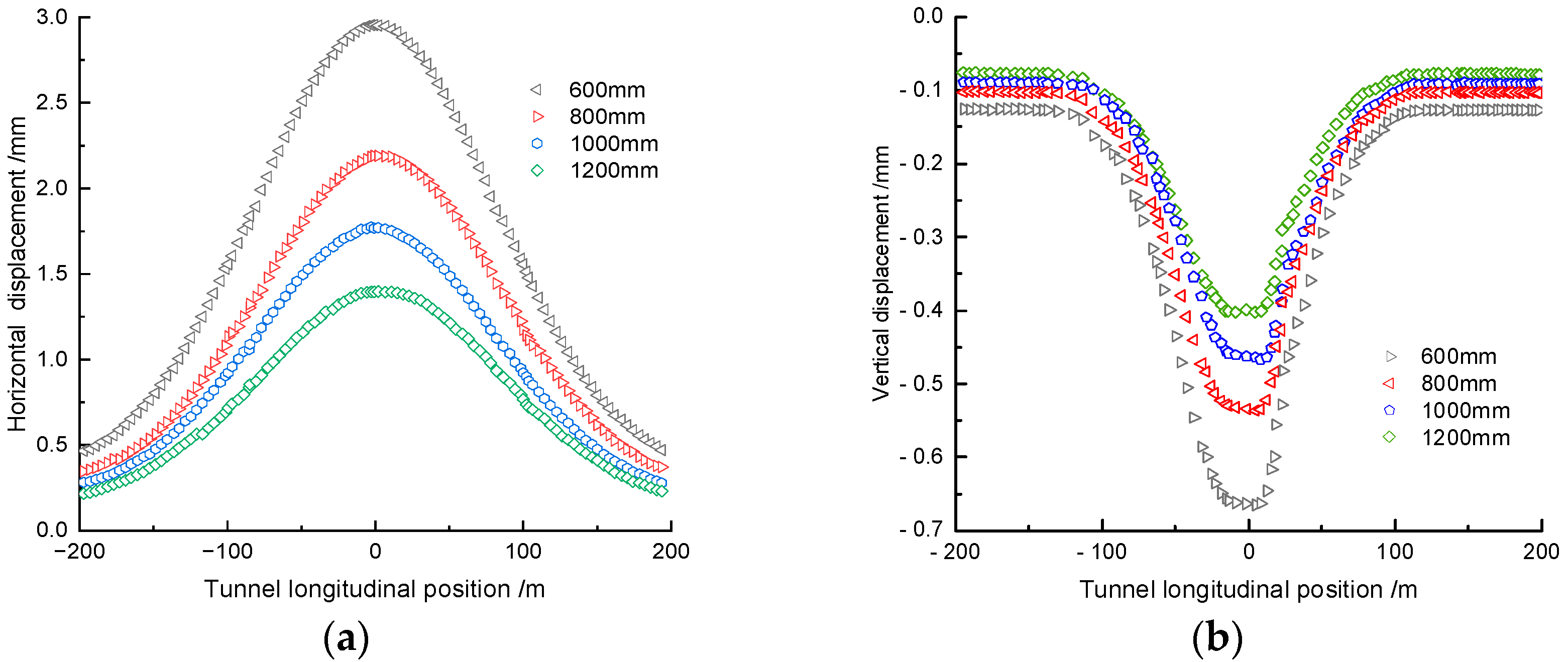
The underground continuous wall plays an indispensable role in deep foundation excavation support projects as it has the ability to withstand substantial soil pressures. The deformation of the tunnel under different wall thicknesses is shown in Figure 9. An increase in the wall thickness of the underground continuous wall can reduce the displacement of the surrounding soil near the foundation pit. Consequently, the smaller the thickness of the underground continuous wall, the more severe the impact on the tunnel. Meanwhile, in Figure 9, the variation patterns of horizontal and vertical displacements of the tunnel are similar. With an increasing wall thickness, the deformation extent of the tunnel gradually decreases, and the deformation rate also reduces. By increasing the thickness of the underground continuous wall, the displacement of the surrounding soil near the foundation pit can be effectively reduced, and the tunnel’s deformation can be minimized. This further proves the crucial role of the underground continuous wall in deep foundation excavation projects.

Figure 9.
Influence of ground wall thickness on tunnel deformation. (a) Horizontal displacement; (b) vertical displacement.
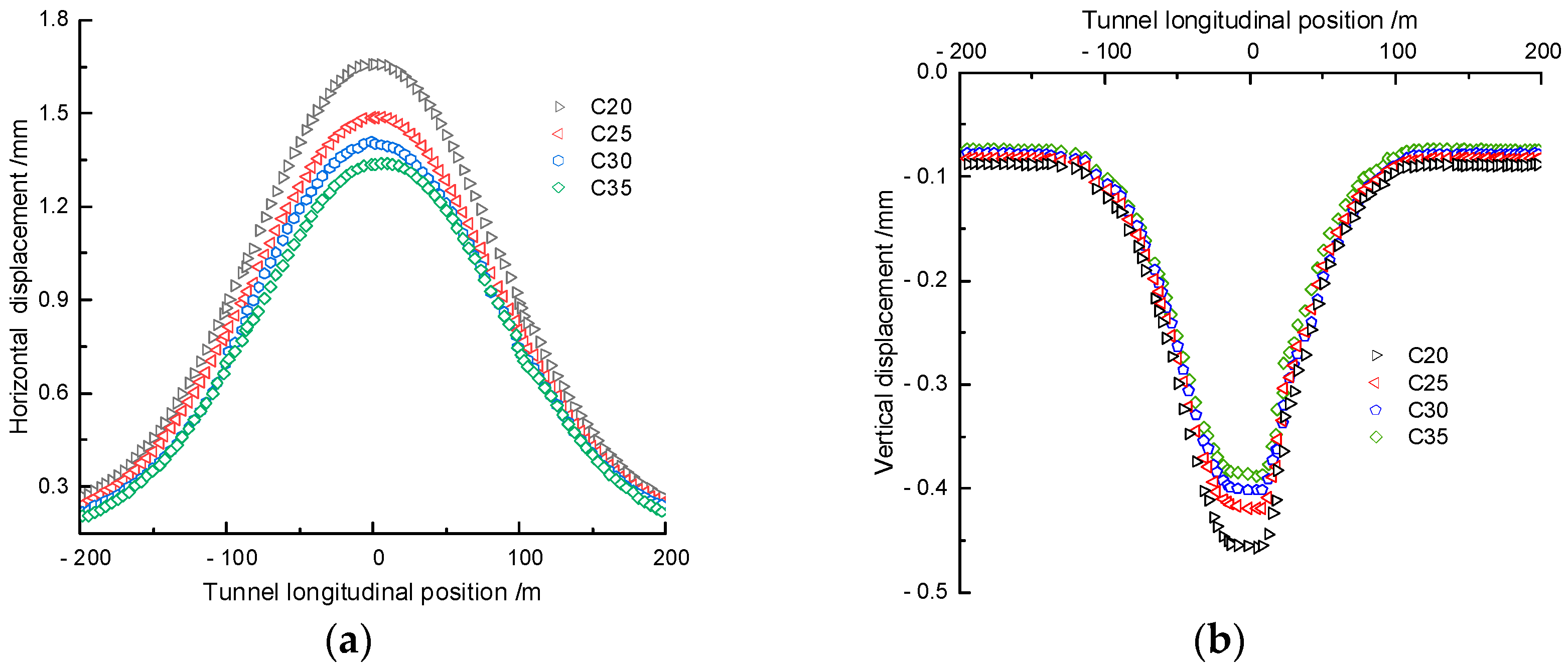
5.2.2. Influence of Wall Material
Currently, concrete is commonly used as the material for the underground continuous wall in excavation projects. Different types of concrete mainly differ in their elastic modulus. The elastic moduli of different concretes are shown in Table 4.
Table 4.
Elastic modulus of concrete.
The response of the tunnel when using different types of concrete for the underground continuous wall is shown in Figure 10. The elastic modulus of the underground continuous wall reflects its deformation capacity. The higher the elastic modulus, the greater the deformation capacity of the underground continuous wall, which can reduce soil displacement and decrease tunnel deformation. In Figure 10, the variations in horizontal and vertical displacements of the tunnel structure are relatively small. With an increase in the elastic modulus of the underground continuous wall, the displacements decrease, and the curves show a pattern of higher values in the middle and lower values on the sides. The elastic modulus of the underground continuous wall significantly affects the reduction of soil displacement and the decrease in tunnel deformation. Selecting concrete materials with higher elastic moduli can enhance the deformation capacity of the underground continuous wall, thereby improving the stability and safety of the project.
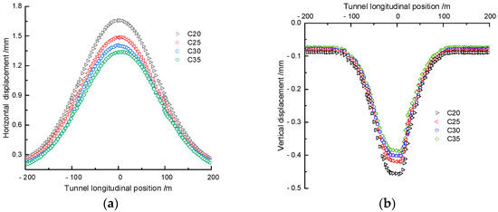
Figure 10.
Influence of ground wall material on tunnel deformation. (a) Horizontal displacement; (b) vertical displacement.
6. Influence of Foundation Pit Excavation Parameters
6.1. Impact of Excavation Depth
With the soil layer, tunnel, and foundation pit retaining structure parameters kept constant, the effect of different foundation pit excavation depths (11 m, 23 m, 28 m, 32 m, and 37 m) on the deformation of adjacent tunnel structures was analyzed. The calculated results are shown in Figure 11. From Figure 11, it can be observed that foundation pit excavation leads to deformation of the adjacent metro tunnel structure, and as the excavation depth of the foundation pit increases, the deformation effect becomes more evident. When the foundation pit depth is 11 m, the maximum vertical and horizontal displacements of the tunnel structure (near the foundation pit side) are 0.4 mm and 1.4 mm, respectively. When the foundation pit depth is 23 m, the maximum vertical and horizontal displacements of the tunnel structure are 2 mm and 3.4 mm, respectively. When the foundation pit depth is 37 m, the maximum vertical and horizontal displacements of the left tunnel are 3.19 mm and 6.37 mm, respectively. As the foundation pit excavation depth increases, the deformation of the tunnel will exceed the deformation control value. Therefore, in practical engineering, attention should be paid to adopting additional reinforcement measures to avoid affecting the safety of the operating metro.
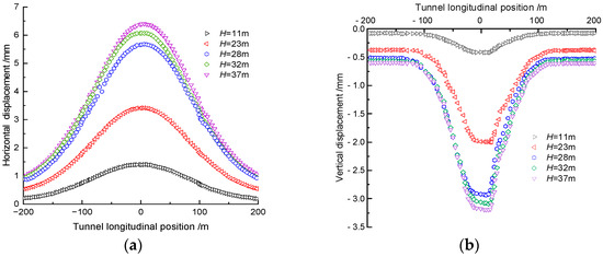
Figure 11.
Tunnel structure deformation at different pit depths. (a) Horizontal displacement; (b) vertical displacement.
6.2. Impact of Excavation Length
For “long excavation” scenarios of the foundation pit (i.e., the foundation pit width B remains constant while the excavation length L increases), as L increases, the maximum displacement wmax of the tunnel increases significantly, and the area affected by the foundation pit excavation on the tunnel also increases notably. Long excavation not only affects the magnitude of tunnel displacement but also changes the uplift range of the tunnel.
It is worth noting that when L is approximately nine times the foundation pit excavation depth (L = 9d), wmax reaches its maximum value, and thereafter, wmax does not continue to increase with further increases in L. However, with increasing L, the uplift range of the tunnel still increases. Figure 12 shows the curve of wmax versus L/d for long excavation scenarios. It can be observed that the curve follows a non-linear increasing pattern of “rapid increase followed by a slow increase”. When L is increased to 9d, wmax increases rapidly. However, for a given foundation pit excavation area (L × B), further increasing L does not significantly affect the tunnel displacement, and the displacement of the tunnel tends to stabilize. Therefore, in the design and construction process, a reasonable evaluation of the long excavation of the foundation pit should be conducted, and corresponding support measures should be taken to control the tunnel displacement and ensure tunnel stability.
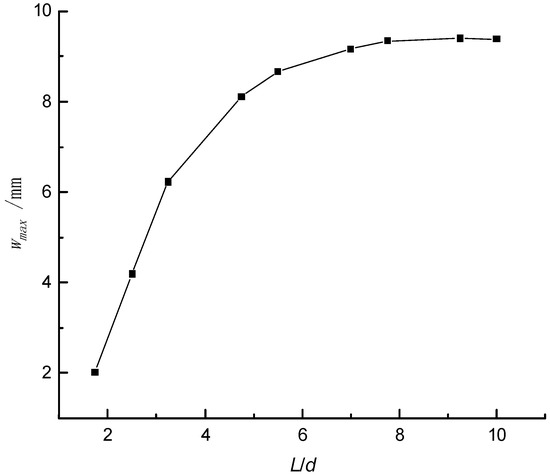
Figure 12.
Maximum displacement curve of tunnel under different excavation lengths of foundation pit.
7. Influence Analysis of Geotechnical Parameters
7.1. Impact of Elastic Modulus
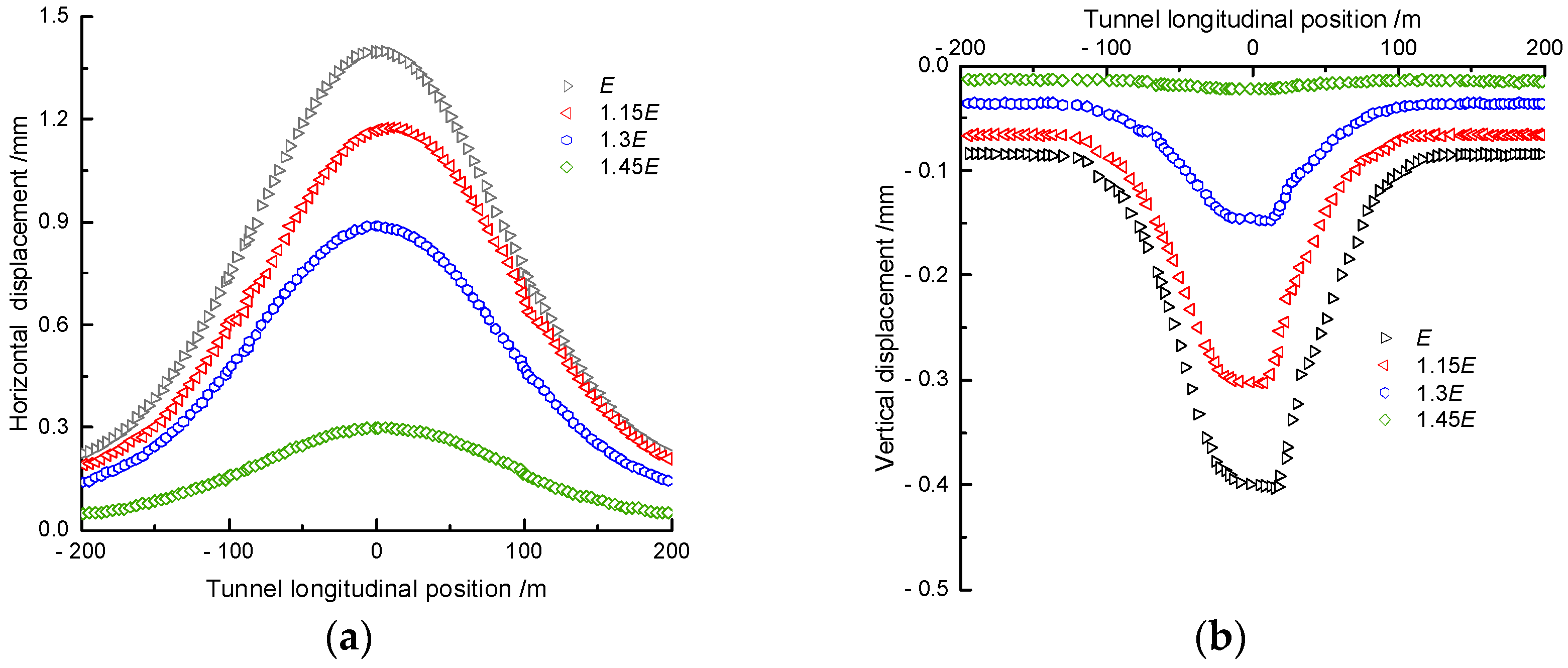
In the context of geotechnical survey design in Shenzhen, the values of soil parameters were found to exhibit a degree of variation. Values of 15%, 30% and 45% were identified as representative of this variation. Based on the original design parameters, considering the differences in elastic modulus of different soil layers, various scenarios were designed and calculated by increasing the elastic modulus of each soil layer by 15%, 30%, and 45%, respectively, while keeping other parameters constant. The variations in tunnel displacement were studied.
The relationship between tunnel displacement and the soil elastic modulus is shown in Figure 13. With the continuous increase in the elastic modulus, the lateral deformation and settlement of the tunnel further decrease. Additionally, as the elastic modulus increases to 45%, the reduction rate of tunnel displacement also increases. The distribution pattern of tunnel deformation remains consistent, with the maximum values of horizontal displacement and settlement located in the central region of the excavation. The changes in displacement are most significant within the excavation range (−90 m~90 m). Therefore, considering the differences in elastic modulus of different soil layers has a noticeable impact on tunnel displacement. As the soil’s elastic modulus increases, the lateral deformation and settlement of the tunnel decrease. These results have important guiding significance for displacement control in engineering design and construction processes.
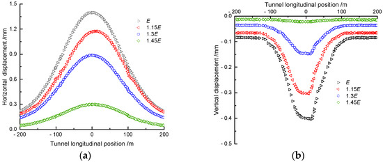
Figure 13.
Influence of increasing elastic modulus on tunnel deformation. (a) Horizontal displacement; (b) vertical displacement.
7.2. Impact of Internal Friction Angle
Similar to the elastic modulus analysis, based on the original design parameters, the internal friction angle of the soil was increased by 15%, 30%, and 45%, respectively, to investigate the tunnel deformation upon completion of excavation. The relationship between tunnel displacement and soil internal friction angle is shown in Figure 14. With an increase in the internal friction angle, the tunnel deformation gradually decreases. This is because the internal friction angle reflects the frictional properties between soil particles, and an increase in the internal friction angle leads to an increase in the frictional resistance, thereby reducing the soil’s deformation.
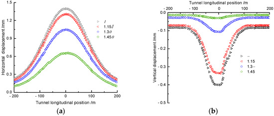
Figure 14.
Influence of increasing internal friction angle on tunnel deformation. (a) Horizontal displacement; (b) vertical displacement.
Numerically, with an increase in the soil’s internal friction angle, the lateral displacement gradually decreases. The variation in the internal friction angle also significantly affects tunnel displacement. The values of horizontal displacement and vertical displacement of the tunnel decrease as the internal friction angle increases. Additionally, as the internal friction angle increases to 45%, the reduction rate of tunnel displacement also increases. The distribution pattern of tunnel deformation remains consistent, with the maximum values of horizontal displacement and settlement located in the central region of the excavation (−90 m~90 m). Moreover, the increase in vertical displacement is greater than horizontal displacement, indicating that the changes in the internal friction angle have a larger impact on tunnel settlement, with higher sensitivity.
Therefore, increasing the soil’s internal friction angle can reduce tunnel deformation. With an increase in the internal friction angle, the frictional resistance between soil particles increases, resulting in reduced soil deformation and, consequently, reduced tunnel deformation. These results are of significant importance for displacement control in engineering design and construction processes.
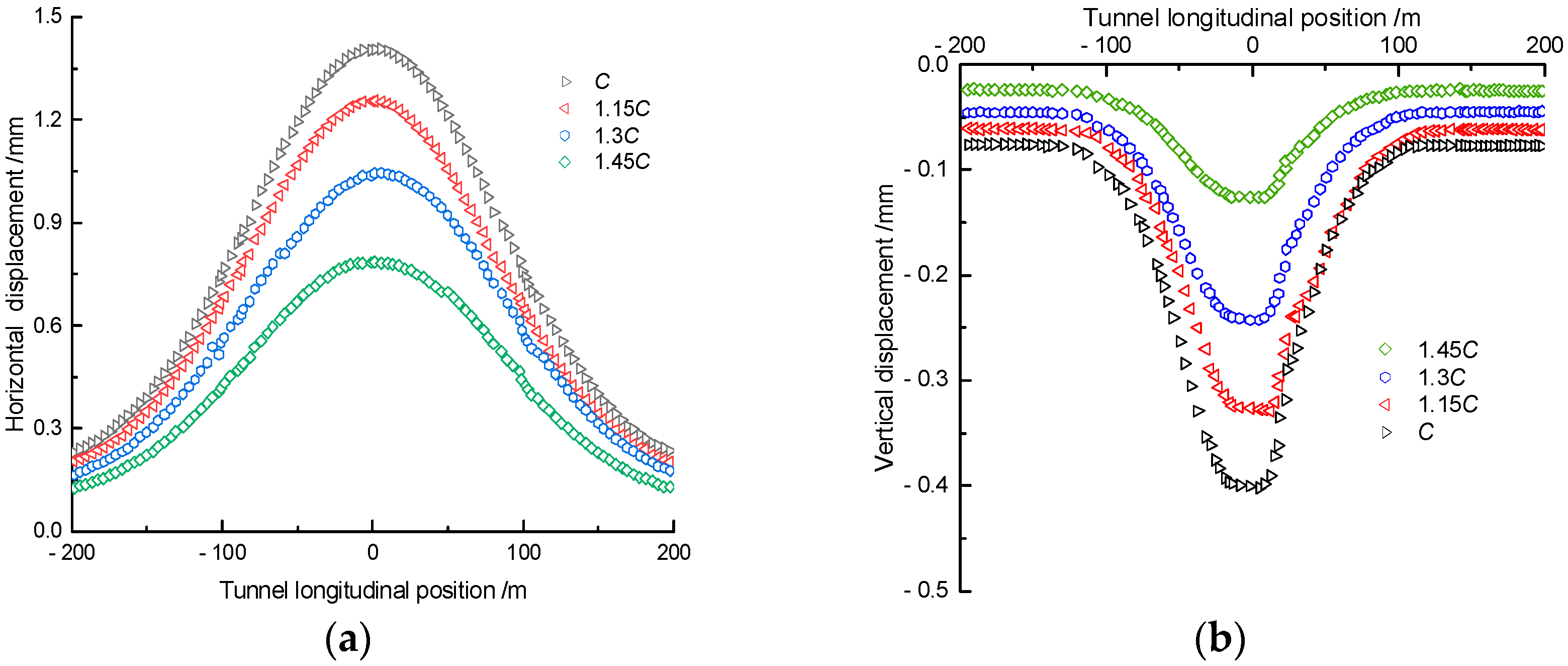
7.3. Impact of Cohesion
On the basis of the original design parameters, the cohesion of the soil was increased by 15%, 30%, and 45%, respectively, to investigate the structural deformation of the tunnel upon completion of excavation. The relationship between tunnel displacement and soil cohesion is shown in Figure 15. With an increase in the cohesion of the soil, the tunnel’s displacement and deformation gradually decrease. This is because the increase in cohesion enhances the physical and chemical forces between soil particles, thus reducing the soil’s deformation.
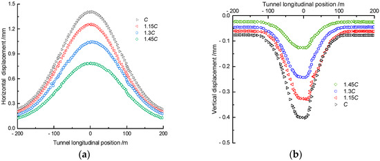
Figure 15.
Influence of increasing cohesion on tunnel deformation. (a) Horizontal displacement; (b) vertical displacement.
Numerically, with an increase in the soil’s cohesion, the lateral displacement gradually decreases. The changes in cohesion also have a significant impact on tunnel deformation, with the values of horizontal and vertical displacements decreasing as the cohesion increases. Additionally, as the cohesion increases to 45%, the reduction rate of tunnel displacement also increases. The distribution pattern of tunnel deformation remains consistent, with the maximum values of horizontal displacement and settlement located in the central region of the excavation, while the largest variations in displacement occur within the excavation range.
7.4. Sensitivity Analysis of Parameters
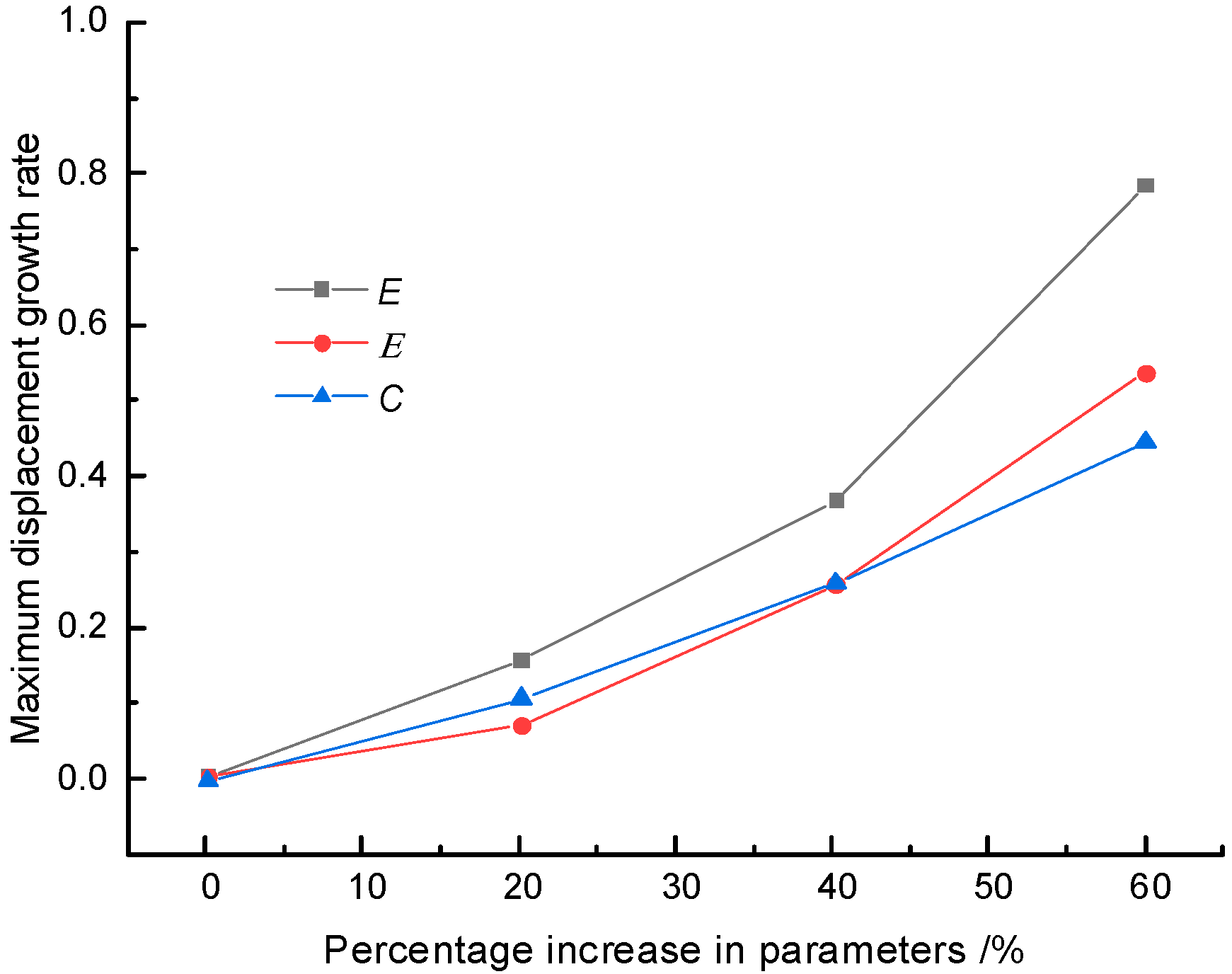
As shown in Figure 16, by analyzing the impact curves of parameter variations on the maximum displacement growth rate of the tunnel, it can be observed that the increase in displacement does not exhibit a simple linear growth but rather a process of gradually accelerating growth. Among these parameter variations, the increase in elastic modulus has the most sensitive influence on tunnel displacement, with both its growth rate and acceleration exceeding those of the internal friction angle and cohesion. The effect of the internal friction angle on displacement follows next. Considering that the lateral deformation of the tunnel is usually greater than the vertical deformation, the elastic modulus is chosen as the most sensitive parameter affecting the overall tunnel displacement, followed by the internal friction angle, while the variation in cohesion has the least impact on displacement.
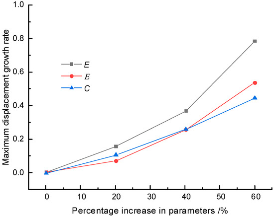
Figure 16.
Comparison of sensitivity of each parameter to station and tunnel deformation.
These results are of significant importance for displacement control in engineering design and construction processes. In practical engineering, particular attention should be given to the influence of elastic modulus on displacement, and corresponding measures should be taken to control the changes in elastic modulus during design and construction. At the same time, the changes in the internal friction angle also require careful consideration and adjustments. Although the effect of cohesion variation on displacement is relatively small, it still needs to be comprehensively considered during the design process. By comprehensively analyzing the influence of these parameter variations on displacement, it is possible to better control and manage displacement issues in engineering projects.
8. Conclusions
This study investigated the rare case of the nearby metro tunnel in the construction of the Zhongxing Headquarters Seaside Deep Foundation Pit Project through theoretical analysis and numerical simulation. The following conclusions were drawn:
- (1)
- To overcome the shortcomings of treating the tunnel structure as a uniformly elastic foundation beam in traditional algorithms, this study treated the metro structure as an elastic foundation short beam connected by shear springs, which made the calculation of the uneven deformation caused by the foundation pit excavation near the metro tunnel more reasonable.
- (2)
- Increasing the tunnel’s own stiffness (EI)eq can effectively reduce wmax, and the weakening effect of (EI)eq on wmax gradually diminishes with the increase in stiffness. The tunnel displacement decreases with the increase in the thickness of the underground continuous wall and the concrete strength. The “long excavation” of the foundation pit not only affects the magnitude of tunnel displacement but also changes the uplift range of the tunnel, posing a greater hazard to the tunnel, and the greater the depth of foundation pit excavation, the larger the deformation of the tunnel.
- (3)
- Tunnel displacement decreases with an increase in the soil’s cohesion, elastic modulus, and internal friction angle. Among them, the elastic modulus is the most sensitive parameter affecting the overall tunnel displacement, followed by the internal friction angle, while the variation in cohesion has the least impact on displacement.
Author Contributions
Conceptualization, S.L. and F.M.; methodology, S.L.; software, Q.W. and F.M.; formal analysis, Q.W. and F.M.; investigation, Q.W.; writing—original draft, S.L.; funding acquisition, F.M. All authors have read and agreed to the published version of the manuscript.
Funding
National Natural Science Foundation of China (51474045).
Data Availability Statement
The original contributions presented in the study are included in the article, further inquiries can be directed to the corresponding authors.
Conflicts of Interest
The authors declare no conflicts of interest.
References
- Dong, X.; Mei, L.; Yang, S.Y.; He, L. Deformation Response Research of the Existing Subway Tunnel Impacted by Adjacent Foundation Pit Excavation. Adv. Mater. Sci. Eng. 2021, 2021, 5121084. [Google Scholar] [CrossRef]
- Zhang, J.C. Analysis of the Impact of Deep Foundation Pit Excavation on the Safety of Adjacent Metro Structures: Review of “Analysis of Typical Accident Cases of Metro Structural Safety Protection”. Ind. Constr. 2021, 51, 231. [Google Scholar]
- Qiao, J.G.; Peng, R.; Li, J.W.; Guo, F. Study on the Impact of Foundation Pit Excavation on Tunnel Safety Based on Modified Mohr-Coulomb Model. China Saf. Sci. Technol. 2022, 18, 177–183. [Google Scholar]
- Duan, Z.H. Analysis of the Safety Impact of Deep Large Foundation Pit Excavation on Existing Subway Interval Tunnel. Build. Struct. 2020, 50, 747–752. [Google Scholar]
- Bian, R.; He, L.; Yan, Y.Z.; Wu, B. Study on the Deformation of Foundation Pit Retaining Structure and its Influence on Adjacent Existing Tunnels. Build. Struct. 2021, 51, 1532–1537. [Google Scholar]
- Zhang, M.; Yan, L.; Pan, C.W.; Liu, W.B.; Xie, M. Impact of Deep Foundation Pit Construction on Safety of Adjacent Metro Station. J. Civ. Eng. Manag. 2020, 37, 99–104+121. [Google Scholar]
- Wang, G.; Zhang, X.W.; Liu, X.Y.; Gao, H.D.; An, R.; Yin, S. Experimental assessment of clayey layers for clogging potential in TBM tunnel driving and the influence of compositional factors. Tunn. Undergr. Space Technol. 2023, 137, 105113. [Google Scholar] [CrossRef]
- Fu, Y.B.; Wang, B.L.; Wu, H.; Chen, X.S.; Sun, X.H.; Bian, Y.W.; Shen, X. Theoretical analysis on horizontal rectification of tunnel near deep foundation pit by grouting. Tunn. Undergr. Space Technol. 2023, 133, 104977. [Google Scholar] [CrossRef]
- Zhang, Q.; Hou, L.L.; Hu, J.; Wang, J.; Lin, P.; He, P.; Song, S.G. Study on the mechanical behavior of a foundation pit retaining structure adjacent to the pile foundation of a subway station. Environ. Earth Sci. 2021, 80, 704. [Google Scholar] [CrossRef]
- Zhang, X.H.; Wei, G.; Jiang, C.W. The study for longitudinal deformation of adjacent shield tunnel due to foundation pit excavation with consideration of the retaining structure deformation. Symmetry 2020, 12, 2103. [Google Scholar] [CrossRef]
- Huang, M.S.; Li, H.; Yu, J.; Zhang, C.R.; Ni, Y.P. Analysis method of longitudinal deformation of adjacent subway tunnel caused by upper foundation pit excavation. Chin. J. Geotech. Eng. 2023, 45, 1–9. [Google Scholar]
- Wei, G.; Guo, B.L.; Wang, Z.; Liu, J.Y. Calculation of deformation in underlaid shield tunnel induced by foundation pit unloading considering excavation width. J. Rock Mech. Eng. 2023, 42, 1019–1030. [Google Scholar]
- Niu, Y.G.; Wang, Q.Y.; Ma, F.H. Study on the Influence of Foundation Pit Excavation on the Deformation of Adjacent Subway Tunnel in the Affected Area of Fault Zones. Sustainability 2023, 15, 9462. [Google Scholar] [CrossRef]
- Wang, Z.X.; Shi, C.H.; Gong, C.J.; Cao, C.Y.; Liu, J.W.; Peng, Z. Analytical Calculation Method for the Influence of Adjacent Station (Shaft) Foundation Pit Excavation on Downward Shield Tunnel. Rock Soil Mech. 2022, 43, 2176–2190. [Google Scholar]
- Wei, Z.K.; Chen, J.; Chen, B.; Huang, Y.H. Study on the Deformation Effect of Soft Soil Foundation Pit Excavation on Adjacent Existing Tunnels. People’s Yangtze River 2022, 53, 198–206. [Google Scholar]
- Chen, R.P.; Liu, M.C.; Meng, F.Y.; Li, Z.C.; Wu, H.L.; Cheng, H.Z. Study on Lateral Force and Deformation of Adjacent Shield Tunnel Structure Caused by Foundation Pit Excavation. Chin. J. Geotech. Eng. 2023, 45, 24–32. [Google Scholar]
- Liu, J.W.; Xue, B.S.; Wang, H.B.; Zhang, X.M.; Zhang, Y.X. Numerical Study on the Behavior of an Existing Tunnel during Excavating Adjacent Deep Foundation Pit. Sustainability 2023, 15, 9740. [Google Scholar] [CrossRef]
- Feng, G.H.; Xu, C.J.; Zheng, M.W.; Xue, W.J.; Yang, K.F.; Guan, L.X. Study on the Longitudinal Deformation of Downward Existing Tunnel Induced by Foundation Pit Excavation Considering Shear Deformation. China Railw. Soc. 2022, 44, 132–141. [Google Scholar]
- Wu, L.L.; Wang, W.; Zhong, Y.; Ren, Z.Y.; Wang, Y.; Guo, D. Field measurement analysis of soft soil deep foundation pit excavation on the underlying subway tunnel. J. Guilin Univ. Technol. 2023, 43, 1–7. [Google Scholar]
- Zhao, X.; Li, Z.W.; Dai, G.L.; Wang, H.X.; Yin, Z.W.; Cao, S.N. Numerical Study on the Effect of Large Deep Foundation Excavation on Underlying Complex Intersecting Tunnels. Appl. Sci. 2022, 12, 4530. [Google Scholar] [CrossRef]
- Zheng, G.; Pan, J.; Cheng, X.S.; Bai, R.B.; Du, Y.M.; Diao, Y. Study on Passive and Grouting Active Control of Longitudinal Deformation of Downward Existing Tunnel Induced by Foundation Pit Excavation. Chin. J. Geotech. Eng. 2019, 41, 1181–1190. [Google Scholar]
- Wei, G.; Zhao, Y.; Sun, Q. Prediction of the effect of foundation pit excavation on shield tunnel with lower anti-floating anchor rod. J. Undergr. Space Eng. 2022, 18, 603–610. [Google Scholar]
- Wu, H.N.; Feng, D.L.; Liu, Y.; Lan, G.Z.; Chen, R.P. Control of downward tunnel deformation during foundation pit excavation based on gantry anti-floating frame. J. Shanghai Jiaotong Univ. 2022, 56, 1227–1237. [Google Scholar]
- Liu, B.; Zhang, D.W.; Li, J.C. Prediction formula and engineering application of side tunnel deformation caused by foundation pit excavation based on multiple case statistics. Rock Soil Mech. 2022, 43, 501–512. [Google Scholar]
- Zhou, S.H.; He, C.; Xiao, J.H. Energy calculation method for deformation of adjacent metro shield tunnel caused by foundation pit excavation under staggered platform effect. J. China Railw. Sci. 2016, 37, 53–60. [Google Scholar]


Disclaimer/Publisher’s Note: The statements, opinions and data contained in all publications are solely those of the individual author(s) and contributor(s) and not of MDPI and/or the editor(s). MDPI and/or the editor(s) disclaim responsibility for any injury to people or property resulting from any ideas, methods, instructions or products referred to in the content. |
© 2024 by the authors. Licensee MDPI, Basel, Switzerland. This article is an open access article distributed under the terms and conditions of the Creative Commons Attribution (CC BY) license (https://creativecommons.org/licenses/by/4.0/).