Review

Long-Term Behavior of Timber–Concrete Composite Structures: A Literature Review on Experimental and Numerical Investigations

by
Benkai Shi
1,*,
Xuesong Zhou
1,
Haotian Tao
2,
Huifeng Yang
1,* and
Bo Wen
1,3
1
College of Civil Engineering, Nanjing Tech University, Nanjing 211816, China
2
School of Civil Engineering, Southeast University, Nanjing 211189, China
3
College of Architecture, Sanjiang University, Nanjing 210012, China
*
Authors to whom correspondence should be addressed.
Buildings 2024, 14(6), 1770; https://doi.org/10.3390/buildings14061770
Submission received: 12 April 2024 / Revised: 23 May 2024 / Accepted: 6 June 2024 / Published: 12 June 2024
(This article belongs to the Special Issue Performance Analysis of Timber Composite Structures)

Abstract

:
Timber–concrete composite structure is a type of efficient combination form composed of concrete floors and timber beams or floors through shear connectors, and shows good application potential in the floor system of timber buildings. The long-term performance of the timber–concrete composite structures is complex and is affected by the creep of timber and concrete, as well as the long-term slip of the shear connectors. This article presents a comprehensive overview of the research status on the long-term behavior of timber–concrete composite members and different shear connectors. For the shear connectors, the effects of loading levels, environments, and component materials on their creep coefficients are summarized. As to the timber–concrete composite members, both the experimental and numerical investigations are gathered into discussions: the connection types, component materials, loading conditions, and durations in the long-term tests are also discussed; various models for describing long-term behavior of timber, concrete, and connection systems are provided, and then a comprehensive description of the progress of numerical investigations over the last decades is made. In addition, the suggestions for future research are proposed to reach a clearer understanding of the bending mechanisms and mechanical characteristics of timber–concrete composite structures.

1. Introduction

In recent years, timber–concrete composite (TCC) structures have been widely applied in projects related to buildings and bridges due to the sustainable and renewable advantages of the wood and significant compression behaviors of the concrete [1,2].
Generally, a TCC structure includes two typical structural forms, i.e., a TCC beam with timber beams and a TCC floor with a timber slab, as shown in Figure 1. The timber beams/slab are connected with concrete slabs via shear connectors. Common connectors mainly include the dowel-type [3,4,5], notched-screw [6,7], glued-in type [8,9,10], and adhesively bonded connectors [11]. The engineering wood adopted in the TCC floor primarily involves the mass timber floor [12,13,14], cross-laminated timber (CLT) [15,16], stressed-laminated timber (SLT) [17], nailed laminated timber (NLT) [18], and so on, while that used in the TCC beam mainly include glued laminated timber (glulam) and laminated veneer lumber (LVL) [19,20]. In addition, the bamboo can replace timber to form a bamboo–concrete composite structure, with a bending mechanism similar to the TCC structure [21,22].
Thanks to the application of concrete slabs, the TCC structure shows a higher structural performance, fire resistance, and vibration and sound insulation in timber building floor systems compared with pure timber floors [23,24,25,26]. What is more, concrete slabs also provide protection for the timber beams from direct contact with water and frictional damage from vehicles when used in timber bridges, which is crucial to prolong the durability of timber bridges [27].
Besides the material properties of timber and concrete, the shear behaviors of connectors between timber and concrete also dramatically influence the bending performance of TCC structures. Existing experimental and numerical programs [28,29,30] have been conducted to explore the bending performances of TCC structures with various connectors with different configurations, and to propose corresponding design suggestions. Basically, the inclined screwed connectors exhibit significant shear performance in terms of bearing capacity, slip modulus, and ductility, among various dowelled-type shear connectors, which is attributed to the contribution of the pull-out resistance of inclined screws [31,32,33]. The notched-screw connectors are characterized by high slip modulus and shear strength but low ductility, and the main failure modes are the shear failure of timber and concrete [6,16,34]. Existing investigations [6,35,36] have found that the self-tapping screw reinforcement for the timber in shear and steel-bar reinforcement for the concrete in shear can effectively improve their brittle shear failure. Moreover, adopting ultra-high-performance concrete can improve the brittle shear failure of concrete tenons [37]. The shear behaviors of glued-in steel-plate connectors mainly depend on the length and width of the steel-plate [38,39,40], which also shows the advantage of continuous arrangement similar to the adhesively bonded connectors.
Timber and concrete display different creep behaviors; the concrete shrinks while timber shrinks or swells under the varying relative humidity (RH) and temperature of the surrounding environment [41,42,43]. In addition, the interfacial slip of the shear connector also gradually increases under long-term load. Accordingly, the long-term behavior of TCC structures is more complex than that of the pure timber beams or floors and concrete floors. Considering the non-negligible composite action of the shear connectors, both the long-term slip of shear connectors and the long-term deformation of the TCC structures are the research hotspots in recent years. Khorsandnia et al. [44] summarized the preliminary studies about the long-term behavior of TCC structures using experimental and numerical methods, with an emphasis on the importance of the effect of concrete creep and connector systems on the long-term behavior of TCC structures. Yeoh et al. [45] conducted a literature review on the long-term tests on TCC beams and connectors performed before the year 2011 and proposed that improving the initial bending stiffness and adopting low-shrinkage concrete are effective measures minimizing the long-term deflection of TCC structures. Since then, numerous experimental and numerical studies about the long-term behavior of TCC structures have been reported, which require a systematic summary to gain insight into the existing problems and development tendencies.
This paper aims to systematically synthesize existing experimental and numerical studies on the long-term performance of shear connectors and TCC structures. Their creep coefficients and deformation increments are summarized, and the effects of the experimental environment, connector types, and component materials on the long-term behaviors of shear connectors and TCC structures are discussed. Furthermore, the creep mechanics of timber and other components as well as the development of numerical investigation are presented. Finally, calculation methods suggested by existing standards are put forward. By critically analyzing recent research and identifying unresolved issues, this paper seeks to provide a comprehensive overview of the current state of TCC long-term behavior research and to propose directions for future studies.
The review is structured as follows: Section 2 discusses the creep behavior of common shear connectors; Section 3 reports experimental and numerical findings on the long-term performance of TCC structures; Section 4 provides a comparison of several design codes; Section 5 concludes with insights into potential improvements and areas for future research. Through this detailed examination, we aim to enhance the understanding of the long-term performance of TCC structures and promote their application.

2. Long-Term Behaviors of Shear Connectors

The long-term behavior of shear connectors is explored with push-out tests, which are also commonly adopted in short-term tests. The long-term loading level mostly adopted is 30% of the ultimate load of shear connectors. The creep coefficient of shear connectors can be determined as the ratio of the slip increment and initial slip, as shown in Equation (1):
φ ( t ) = s ( t ) s ( t 0 ) s ( t 0 )
where s(t) and s(t0) are the present slip and initial relative slip, respectively.
As to the determination of the initial relative slip s(t0), the following two measures are recommended: (i) the slip/displacement when the load is applied for about 10 min, aiming to eliminate the vibration interference caused by the application of weights [46] and (ii) the slip/displacement corresponding to the applied long-term load obtained from short-term tests [47].
A summary for the results of long-term tests performed on shear connectors of TCC structures is listed in Table 1. The long-term loading level, the environmental conditions, and the loading period were summarized. Generally, shear connectors used in TCC structures mainly include three types, i.e., dowel-type connectors, notched-screw connectors, and glued-in or adhesively bonded connectors. For the dowel-type and notched-type connectors, the experimental results are summarized in Table 1. However, authors need help finding and reviewing relevant reports for the glued-in steel-plate connectors, while one study about adhesively bonded connection used in TCC structures was found and counted. In addition, typical configurations of shear connectors are depicted in Figure 2.

2.1. Dowel-Type Connectors

Van de Kuilen et al. [48] performed a series of long-term tests on dowel-type connectors of TCC beams. Three types of dowels were used, including the 8 mm smooth dowel, 10 mm smooth dowel, and 10 mm profiled dowel (see Figure 2a); in addition, a 20 mm thick plywood was inserted amid the timber and concrete in one group of specimens (see Figure 2b). The specimens in groups V1~V3 were tested in a controlled environmental condition with a temperature (T) of 20 ± 2 °C and RH of 65 ± 5%, which was close to service class 1, in contrast to those in groups V4~V5 which were tested in indoor uncontrolled conditions close to service class 2 according to Eurocode 5 [49]. The long-term tests found that increasing the diameter of dowels and adopting conventional concrete can decrease the creep coefficient, while increasing the interlayer plywood failed to result in an obvious increase in the creep coefficient for dowelled shear connectors.
Fragiacomo et al. [50] developed a “Tecnaria” stud connection system (see Figure 2c) and investigated its long-term behaviors under constant (T = 24 °C, RH = 70%) and cyclic environmental conditions. In addition, the concrete types considered included normal weight concrete (NC) and light-weight aggregate concrete (LWAC). It was found that the use of LWAC slightly declined the creep coefficient of TCC shear connectors which showed an evident mechano-sorptive creep increment in the specimens sustained in an environment where the humidity changed significantly. In addition, the creep recover was determined to be 0.24 through unloading the specimens.
Jorge et al. [51] also investigated the long-term behavior of shear connection specimens made of LAWC. The diagonally crossed self-taping screws (STS, VB48-7.5×100, see Figure 3) were adopted as shear connectors. The long-term tests were conducted in a constant environment (20 °C/65% RH). The test results indicated no influence of the LWAC strength class on the creep coefficients.
Fragiacomo [52] investigated the long-term slip of TCC shear connectors with inclined STS (see Figure 2d). The STS types adopted were also VB48-7.5×100 screws (see Figure 3). An oriented strand board (OSB) with a thickness of 15 mm was set between the timber and concrete. The slip modulus at the serviceability limit state was 12.0 kN/mm, while the creep coefficient was about 0.66 after 421 days of loading.
Jiang et al. [53] conducted a series of experiments to find out how the type of concrete and environmental condition affect the long-term behavior of vertical coach screw connectors (see Figure 2e). The long-term testing results showed an opposite conclusion versus those found by Fragiacomo et al. [50]. As observed, the one-year creep coefficient of shear connectors with LWAC was 1.2 times that with normal concrete. The change in ambient temperature and humidity imposed a great influence on the creep coefficient of the specimens made of LWAC. In addition, the creep coefficient of the specimens tested in an outdoor sheltered environment was about 2.5 times that of the specimens tested in the indoor environment.

2.2. Notched and Notched-Screw Connectors

Dias et al. [54,55] arranged long-term push-out tests on notched connectors with and without plywood between the timber and concrete (see Figure 2f) for about 500 days. Specimens were placed in an uncontrolled environment related to the service class 2 condition of Eurocode 5 [49]. Tests found that the notched joints have an extremely high creep coefficient, compared with the dowel-type connectors, due to the higher slip stiffness and small initial slip of the notched connectors. In addition, applying the plywood between the timber and concrete caused an increase in the creep coefficient, which was obviously different from the dowel-type connectors reported by Van de Kuilen et al. [48].
Kuhlmann and Michelfelder [56] tested the creep behaviors of notched connectors reinforced with two types of screws (coach screw and STS, see Figure 2g and Figure 2h, respectively). Moreover, the notched connector without the screw was also subjected to long-term loads for 8 months. The timber adopted was nailed laminated timber (NLT). It was found that the screw reinforcement for notched connectors had no regular effect on their long-term slip.
Mueller et al. [57] compared the long-term behaviors of the three TCC connectors, including the trapezoidal notch, trapezoidal notched-stud (Figure 2i), and X type (Figure 2j) connectors. For the X-connector, a tension reinforcing bar and a compression reinforcing bar with a diameter of 14 mm were inclinedly glued into the timber using a two-component epoxy-resin adhesive. All specimens were placed in a sheltered outdoor environment. The experimental results showed that the specimens with trapezoidal notched connectors had remarkably higher creep coefficients than those with trapezoidal notched-studs connectors, due to the relatively small initial slip of the former. Results also indicated that the X-type connector had a rather good long-term behavior since the creep coefficient was only 0.21 after a 600-day period of loading.
Shi et al. [58] conducted push-out tests to determine the long-term interfacial slip of notched-screw connectors. The 0.15 and 0.30 loading levels were considered, corresponding to the 15% and 30% of the load-carrying capacity of shear connectors. After the 342-day loading period, the creep coefficients for the specimens sustained by 0.15 and 0.30 loading levels were 1.38 and 1.30, respectively. This proved that the effect of long-term loading levels on the creep behavior of notched-screw connectors can be negligible.
Shi [59] also carried out the long-term loading tests to investigate the long-term slip of prefabricated connectors consisting of steel-plates and screws (Figure 2k). The long-term tests were performed under a controlled constant environment with an RH of 60 ± 5% and temperature of 20 ± 2 °C. After 1000 days of long-term loading, the average creep increment was about 1.44 mm, and the corresponding creep coefficient was 1.72.
Shi et al. [60] improved the steel-plate connection system by using steel-tubes instead of screws. The 0.2 loading level was adopted in the long-term tests. With a loading duration of 470 days, the creep coefficient of the steel-plate with steel-tube connectors was determined as 3.38. According to collapse tests of the push-out specimens which have sustained the long-term loads for 470 days, both the load carrying capacity and slip modulus revealed no evident decline compared with the specimens tested in short-term collapse tests, demonstrating the good long-term performance of new shear connectors.

2.3. Adhesion Connection

Adhesion connections mainly included adhesively bonded connections and glued-in type connectors. Adhesively bonded connections are generally regarded as rigid connections because the adhesive can be arranged in full coverage at the interface between the timber and concrete, providing sufficient constraint.
Eisenhut et al. [61] investigated the long-term slip of adhesively bonded TCC push-out specimens (Figure 2l). The concrete adopted was high-performance concrete (HPC), and the cycle environment consists of the climatic levels of 20 °C/85% and 45 °C/40%. A wide dispersion of the absolute slip increment was observed for three specimens sustained by long-term loads. The maximum slip increment was 3.59 mm while the minimum slip increment was 1.17 mm over the loading duration of 230 days.
As to glued-in type connectors for TCC structures, no related long-term test was reported to the best of the writer’s knowledge. Similar glued-in rod joints used in timber structures were reported in terms of long-term behavior in some literatures, which can provide guidance for glued-in type connectors of TCC structures.
Lartigau et al. [62] studied the effect of temperature on the shear strength and slip stiffness of timber glued-in rod joints using epoxy. It was found that the joint stiffness decreased obviously when the temperature was above 60 °C. The stiffness joint declined by about 50% when the temperature reached 80 °C, compared with the stiffness at 20 °C. This phenomenon was related to the glass transition temperature (58 °C) of epoxy.
Verdet et al. [63] conducted long-term tests on timber glued-in rod joints to investigate the effects of adhesive types and temperature on the strength and stiffness loss. It was found that the joints using epoxy showed minor strength loss and stiffness loss than the ones using polyurethane (PUR) in high temperatures (40–70 °C). In addition, under the action of high loading levels (60–78%) and in variable climate conditions (service class 1), the glued-in rod joints with epoxy failure during long-term tests, and the stiffness loss of residual specimens ranged from 34 to 26%.
Also, some scholars researched the long-term behavior of glued steel-timber joints, which are widely used in timber truss structures. Cavalli et al. [64] investigated the mechanical performance of the glued steel-timber joints under the extreme environmental conditions. A novelty bicomponent epoxy resin was adopted as the adhesive. The effects of epoxy ageing temperature cycle, high RH (100%), and water immersion on the mechanical performance of the joint were investigated. It was found that high humidity and water immersion contributed to an obvious decline in the strength of the glued steel-timber joints, whereas the high temperature resulted in the higher strength values compared with the low temperature, due to use of the specific epoxy resin.
Larsson et al. [65] proposed a type of glued steel-plate dowel joint and investigate its duration at different long-term loading levels. The joints loaded parallelly to grain and demonstrated a shorter duration and smaller creep coefficient than those loaded perpendicular to grain. While the loading level increased to 0.8 from 0.6, the duration for the joint specimens loaded both parallel and perpendicular to grain decreased obviously.
Shi et al. [47] tested several innovative bonding steel-plate joints of timber structure in the constant environmental condition (RH = 60 ± 5%, T = 20 ± 2 °C). Two groups of specimens, which sustained 0.3 and 0.6 loading levels, respectively, showed creep coefficient of 0.86 and 0.46, respectively, after the loading duration over 800 days. The creep coefficients after 50 years for the specimens with 0.3 and 0.6 loading levels were predicted as 0.918 and 0.502, respectively, by using the six-term Kelvin model.
Figure 4 depicts the typical loading diagram for TCC push-out specimens. The most recommended loading method by authors is to load specimens in series by leverage (Figure 4a), which has the advantage of highly efficient and repeated verification. The loading methods in Figure 4b,c have the advantages of simple design and easy assembly.
Figure 4. Long-term testing setups published by (a) Van de Kuilen et al. [48] and Shi et al. [58]; (b) Fragiacomo [52]; and (c) Jiang et al. [53] and Mueller et al. [57].
Buildings 14 01770 g004
Table 1. Long-term tests of shear connector specimens for TCC structures.
ReferencesConnectorsTimberConcreteLoad LevelEnvironmentsPeriod (d)Creep Coefficient
Van de Kuilen et al. [48]V1, 8 mm smooth dowelGlulam C25/300.3320 °C/65%10000.80
V2, 10 mm smooth dowelC25/300.3111600.57
V3, 10 mm smooth dowelC50/600.3011601.58
V4, 10 mm profiled dowelC30/370.30Indoor6821.11
V5, 10 mm profiled dowel with interlayer 6551.08
Fragiacomo et al. [50]Tecnaria connectorGlulamC20/250.30Constant1030.55
LC9/110.43
Jorge et al. [51]Crossed STSGlulam LC20/220.30Constant6000.908
LC12/130.791
LC16/180.695
Fragiacomo [52]Inclined STS with an OSBGlulamLC25/300.2524 °C/70%4210.66
Jiang et al. [53]Coach screwGlulam C300.30Indoor3650.59
LC300.72
LC30Outdoor, sheltered1.80
Dias et al. [54]NotchGlulamC30/370.30Indoor4912.749
Notch with plywood5144.275
Kuhlmann et al. [56]NotchNLTC20/250.30Outdoor, sheltered2400.56
Notched-coach screw0.44
Notched-STS0.53
Muller et al. [57]Trapezoidal notchGlulamC25/300.30Outdoor, shelteredAbout 6001.25
Trapezoidal notched-studs0.83
X-connector0.21
Shi et al. [58,59,60] Notch-screwGlulam C30/350.15Constant3421.38
0.301.30
Steel-plate with screws10001.72
Steel-plate with steel-tubes0.204703.38
Eisenhut et al. [61]BondingGlulamHPC0.25Cycle climate230-

2.4. Other Connectors of Timber Structures

Many scholars have performed a series of long-term tests on pure timber joints, steel–timber joints, and timber beam-to-column joints, reflecting the creep characteristic of the timber surrounding the metal fasteners. Their loading levels and climates also provide a reference for TCC structures.
Chiniforush et al. [66] tested the creep behavior of four types of novelty steel-CLT screwed and bolted joints, using coach-screw (CS), dog-screw (DS), post-tensioned bolt (PB), and bolt-in-grout-pocket (BGP) connectors (see Figure 5). The results indicated that specimens with grouting-bolt, as a matter of fact, had the lowest creep coefficient (0.8) for the prediction duration of 50 years. As comparisons, the creep coefficients for the specimens with coach-screw, dog-screw, and post-tensioned bolt connectors ranged from 1.0 to 8.8. In addition, it was also demonstrated that increasing the loading level led to a decrease in the creep coefficient.
The existing research mainly focused on the creep deformation of single components and connectors, though studies on the joints are rather scarce owing to the fact that the behavior of beam–column joints is more complicated considering the anisotropy of timber, moment and rotation resisting capacity, the stress redistribution on the joint, etc. For example, Fragiacomo et al. [67] tested the time-dependent moment-resisting and uniaxially loaded behaviors of four timber joints with glued-in steel rods under an uncontrolled indoor environment and concluded that the joint contributed about 50% of displacement in the total frame deflection.
Basically, in beam–column joints, the column is in transverse compression while the beam is in longitudinal compression. Therefore, Zheng et al. [68] investigated the rheological behavior of the timber in different compression directions. It was found that the creep coefficient for the timber in longitudinal compression was 0.546, while that in transverse compression reached 5.181 for a period of about 360 days. Subsequently, Li et al. [69,70,71] conducted a series of post-tensioned timber beam–column joints to explore the long-term prestressing loss as well as the effects of varied environments and different climates on the long-term performance of the joints. It was found that the RH significantly influenced the long-term prestressing force of the joint, and the prestressing force was even larger than the initial value when the timber swelled [70].

3. Long-Term Behaviors of TCC Structures

3.1. Experiments

Long-term bending tests aim to study the global deformation of TCC structures and the collaborative work effect between timber and concrete and under the action of long-term loads. Related long-term testing results are summarized in Table 2. The types of connection systems adopted in available experimental investigations mainly include dowel, notched, and bonding types. Considering that many researchers adopted different types of connectors in the same batch of experiments, the summary of the long-term tests for TCC structures is sorted roughly according to the time reported in these studies. Different from the long-term tests of shear connectors, those of the TCC structures were mainly conducted in an uncontrolled environment.
Ceccotti et al. [72] conducted a long-term experimental test on a TCC beam, which consisted of two glulam beams and a concrete slab. The sustained load represented about 11.1% of short-term bearing capacity. The 5-year loading period results showed that the mid-span deformation was 3.36 mm and increased significantly during the first two years.
Bathon and Beltz [73] investigated the long-term behavior of a TCC floor using glued-in steel meshes. The net span of the TCC floor reached 9860 mm. Under the action of long-term loads of 91 kN, the initial mid-span deflection was 33 mm, and the mid-span deflection increment was 46.3 mm after a duration of 430 days.
Fragiacomo et al. [74] investigated the long-term behavior of TCC floors with novelty shear key/anchor connectors. The impact of the shores between spans on the long-term behavior of the floor specimens was explored. For the shored specimens, the shores were removed 36 days after the concrete was poured. It was found that the impact of the shoring on the long-term deflection of specimens is negligible. The creep coefficients of the shored and unshored specimens were 0.54 and 0.56, respectively, after a loading duration of 133 days.
Similarly, To et al. [75] tested the long-term deformation of NLT–concrete composite floors with notched shear key connectors. The specimens were placed in a wood house with open doors. It was found that the deflection of the specimens was not sensitive to the surrounding changing RH.
Gutkowski et al. [76] reported the long-term behavior of the TCC floor using wood poles. The long-term test involved two steps: (i) the deflection of the TCC floor was 18.9 mm when the concrete (dead load) was poured, and its total deflection reached 31.5 mm after the 28-day the concrete curing; and (ii) the deflection increased by 2.5 mm when the live load was applied, and the incremental deflection was 10.4 mm after 228 days.
Yeoh et al. [77,78] presented a series of 4-year long-term tests performed on TCC floors, considering the connector types (notched-screw and tooth metal plate) and concrete types (NC and low shrinkage concrete (LSC)). The specimens using low shrinkage concrete demonstrated a relatively lower deflection increment and creep coefficient compared with the one using normal concrete. The specimens using tooth metal plate connectors and low shrinkage concrete showed the best long-term behavior with the incremental deflection of 25.5 mm and the creep coefficient of 3.28 after a duration of 4 years.
Fragiacomo and Lukaszewska [79,80] proposed several types of prefabricated connectors and investigated the long-term behavior of TCC beams with prefabricated concrete slabs. The incremental deflection and creep coefficient for the specimens with steel-plate type connectors were 5.62 mm and 1.01, respectively. For the specimens with coach screws, the deflection increment and creep coefficient were 5.28 mm and 0.98, respectively.
Hailu [81] reported four TCC beams sustained by long-term loads in a constant environment, as shown in Table 2. The specimen with wood screws showed the lowest composite efficiency with the initial deflection of 8.24 mm and creep coefficient of about 9.0. In addition, the effects of cycle RH changing on the deflection of TCC beams were analyzed. It was demonstrated that increasing RH (except the first cycle) caused a decrease in the deflection, while decreasing RH led to the increase in the deflection.
Eisenhut et al. [61,82] researched the long-term behavior of the adhesively bonded π-shape TCC bridge beams. Two types of epoxy were adopted as shown in Table 2. All specimens were exposed to the outdoor environment. It was demonstrated that the outdoor environment caused the evident seasonal fluctuations in deflection.
Tannert et al. [83] conducted long-term tests on the TCC floor with a type of two component epoxy, Sikadur-T35-LVP. The longitudinal voids resulted in a 55% bonding area and the transverse voids resulted in a 87% bonding area. The long-term loading levels reached 30% of the estimated capacities. After long-term loading lasting 4.5 years, the creep coefficients were 0.90 and 0.76 for the specimens with longitudinal voids and transverse voids, respectively.
Czabak and Perkowski [84] investigated the long-term behavior of wood–concrete composite beams. About a year after loading, the deflection decreased with the decrease in RH and increased with the increase in RH, which was remarkably different with the results of the Hailu [81].
Kanócz et al. [85,86,87,88] researched the long-term behaviors of various TCC structures with different connectors, engineering wood, and concrete types. The deflection increment and creep coefficient were roughly calculated according to the curve presented by the authors. The annual fluctuation of deflection was obviously observed during long-term tests, which was caused by the seasonal fluctuations in temperature and RH. The specimen with notched connectors demonstrated an average annual fluctuation of 1.3 mm, while the fluctuation of that with screwed connectors was 4.8 mm.
Kong et al. [89] reinforced the glulam with the upper concrete slab and bottom carbon fiber-reinforced polymer rebar (CFRP). After over 1-year-loading, the deflection of the glulam specimen and the hybrid one, which were loaded in indoor conditions, increased by 0.2 and 0.4, respectively. However, a hybrid specimen tested in the outdoor condition exhibited debonding on the 190th day after loading.
Augeard et al. [90] researched the creep behavior of TCC structures with sustained cycle loads. The cycle loads ranged from 4 kN to 20 kN, which represent the dead load and live load, respectively. After 106 loading cycles with the frequency of 1 Hz, the average creep coefficient of three groups of specimens were calculated as 0.25, 0.11, and 0.15, respectively. Among the three groups above, the specimens using ultra-high-performance fiber-reinforcement concrete (UHPFRC) instead of ordinary concrete at the interface between timber and concrete showed the lowest creep coefficient of 0.11.
Jiang et al. [53] conducted a series of long-term tests for TCC beams constructed of normal concrete and LWAC, respectively. In addition, the effects of connector distance (200 mm and 400 mm) and testing environments (indoor and sheltered outdoor) on the long-term behavior of TCC beams were explored. Testing results demonstrated that the specimens with 200 mm and 400 mm screwed spacing showed a creep coefficient of 1.20 and 1.62, respectively, after a loading duration of 365 days. In addition, the outdoor environments demonstrated a significant increase in both incremental deflection and creep coefficient, and the creep coefficient of the specimen reached 2.47 in 365 days.
Hwang et al. [91] reported the moisture content (MC) of the NLT–concrete composite floor exposed to outdoor environments. It was found that the MC of NLT increased with the increase in the ambient RH and the pouring of wet concrete. The average strains of the NLT in width and height directions were 0.54% and 0.67%, respectively, while the strain in the length direction was ignored.
Shi et al. [58,92] proposed a novelty prefabricated TCC beam using steel-plate connectors and made the comparative long-term tests with a pure glulam beam and a TCC beam with notched connectors. Testing results showed that the TCC beam was characterized by a higher creep coefficient than the timber beam as the result of the concrete shrinkage, and the novelty TCC beam proposed showed a creep coefficient of 0.93–1.40, demonstrating good long-term performance. Also, the multi-Kelvin model, Burger model, Logarithmic model, and a hybrid model were adopted to predict the final deflection of the TCC beam, and the final creep coefficients for the prefabricated TCC beam were predicted as 1.14–1.71 at the end of the 50-year service life.
Derikvand et al. [93] researched the long-term behavior of NLT panels. The panel grades and spans were considered in the long-term tests. The elastic moduli of the higher and lower grade panels were 11.76 GPa and 9.27 GP, respectively. The NLT panels with 3600 mm showed the lowest creep coefficient of 0.26 as the results of the highest stressing level. The NLT panels with lower grade board showed the highest creep coefficient of 0.59.
Chiniforush et al. [94] conducted a series of long-term tests performed on steel–CLT composite beams. The main research parameter is the shear connector types. Testing results demonstrated that the specimens with post-tensioned bolted connectors were characterized by the lowest creep coefficient of 0.12 after 20 months while the specimens with hybrid ‘coach screw + grout pocket’ connectors showed a creep coefficient of 0.18. In addition, it was found that the creep coefficient declined to 0.10 when the CLT panel was perpendicularly arranged on the top of the steel beam.
Bajzecerová et al. [95] designed two CLT–concrete composite beams: the specimen PS1 showed the dimensions of 130 mm in height and 4500 mm in length, while the specimen PS2 showed dimensions of 80 mm in height and 6000 mm in length. In addition, the CLT panels were subjected to prestressed forces. The cambers of specimens PS1 and PS2 were 45 mm and 50 mm, respectively. For specimens PS1 and PS2, the anchors were removed on day 49 and 74, respectively. The incremental deflection of specimen PS1 was 10.1 mm 60 days after anchor removal under the action of the member self-weight, and that of specimen PS2 was 9.4 mm 30 days after anchor removal.
Riccadonna et al. [96] tested the long-term behaviors of timber–CLT composite beams with pre-stressed forces. The double-threaded screws and single-threaded screw were adopted as shear connectors. The uniform and variable connector arrangements were considered in the fabrication of the composite beams. Testing results demonstrated that the specimens using double-threaded screws in the beam ends and single-threaded screws in the middle section appeared promising for the practical application of pre-stressing.
As shown in Table 2, distributed loads or two concentrated loads were mostly adopted in long-term bending tests. Several typical loading cases are presented in Figure 6. To simulate the distributed load in the actual project, distributed loads can be achieved by applying continuous or discontinuous weighs (buckets filled with water or mass blocks), as shown in Figure 6a,b. To simulate the load conditions of the 4-point bending test in the short-term bearing capacity test, two concentrated loads can be applied as shown in Figure 6c.

3.2. Numerical Investigation

3.2.1. Rheological Behavior of Wood

The time-dependent behavior of timber is rather complex since timber is a heterogeneous anisotropic material with hygroscopic behavior. Timber is not only affected by long-term loads but also influenced by the temperature of the surrounding environment and the variation in RH. Timber is a hygroscopic building material that constantly absorbs and desorbs water from its surroundings when RH changes. Due to that, timber fibers are always variable in wet or dry conditions. Also, the velocity of adsorption or desorption of moisture was determined by various factors, such as environmental conditions, moisture gradient, and diffusion capacity of wood [97]. At some points, when wood stops absorbing or desorbing, the MC of wood is called equilibrium moisture content (EMC).
Two forms of water have been held in the wood, i.e., free water and bound water. During the wood drying process, when the water in the wood cell cavity (called free water) has been removed, only the water bound in the cell walls (called bound water) remains. The MC at this point is called the fiber saturation point (FSP). When the timber is dried to the FSP, the physical and mechanical properties of wood would be deteriorated [98]. Therefore, the calculation and estimation of MC in wood are crucial for the life cycle and design of timber structures. According to EN 384 [99], the modulus of elasticity of timber should be adjusted by 2% for every per cent difference in MC. The strength of timber, when it reaches FSP, is only approximately half of timber strength in normal conditions. Gulzow et al. [100] tested CLT floors in different environments and found that CLTs in wet conditions had lower stiffness than normal conditions. Additionally, the creep of timber in a cyclic change in RH was more severe than in a controlled environment.
To characterize the rheological components of timber, several viscoelastic models have been proposed [101,102]. Toratti’s model [103] has been widely employed, since it showed a good agreement with experimental data, as long as the maximum stress is less than 20% of the timber strength [104]. In this model, the long-term deformation of timber is separated into a sum of seven components: elastic deformation εwe, viscoelastic creep εwc, strain due to the change in Young’s modulus with the MC εwEu, mechano-sorptive creep εwms, effect of shrinkage/swelling on total strain εwss, hygro-expansion strain εwu, and thermal strain εwT [103,104,105]. Since the histories of strain depend only on thermo-hygrometric environmental variation, they can be regarded as loading conditions. According to the superposition principle, the total strain at a certain time could be expressed as (2):
ε w ( t ) = ε we ( t ) + ε wc ( t ) + ε wEu ( t ) + ε wms ( t ) + ε wss ( t ) + ε wwu ( t ) + ε wT ( t )
It is worth noting that taking these components into account could make the simulation inefficient. In actual numeral investigation, researchers prefer to give emphasis to three major creep parts: viscoelastic creep, mechano-sorptive creep, and creep related to moisture changes.
(a)
Viscoelastic behavior
The deformation that wood displays under long-term loads in a controlled environment is called viscoelastic creep. Viscoelastic creep depends primarily on the loading level and environmental temperature. When the loading level is not higher than 30% of the strength of the timber in a constant environment, the wood will exhibit a linear elastic deformation. When loaded in a changing environment, the viscoelastic behavior of wood becomes nonlinear [106]. Furthermore, when the loading level exceeds a certain value, the creep behavior becomes nonlinear, even if the environmental conditions are constant. In order to describe the various types of viscoelastic creep of wood, many studies have proposed several rheological models.
These models are usually composed of a combination of mechanical elements (i.e., spring and dashpot) to describe the creep behavior [101,103,107]. The spring has been used to simulate the elastic behavior of the wood, and the dashpot presents the behavior associated with time. If the spring and dashpot are connected in series, it is called the Maxwell model; if these two elements are connected in parallel, it is called the Kelvin–Voigt model. The standard linear solid model is formed by the linear combination of a Kelvin model and a spring (Maxwell type) or a dashpot (Kelvin type). Another viscoelastic model that connects the Maxwell model and the Kelvin model in series is called the Burgers model. Viscoelastic creep could be considered recoverable after a sufficient period of time, as result of the comprehensive implementation of the Kelvin element rheological model. Mackenzie-Helnwein and Hanhijärvi [108] derived the rate equation for the i-th Kelvin element, which can be written as follows:
ε ˙ i v e + 1 τ i ε i v e = 1 τ i C i v e 1 : σ
where τi denotes the retardation time for the i-th Kelvin element. C i v e 1 denotes the viscoelastic compliance matrix which corresponds to the elastic compliance matrix [109]. Table 3 displays the viscoelastic parameters of timber and timber joints for numerical investigation by three researchers.
(b)
Mechano-sorptive behavior
The behavior of creep rate increases rapidly when wood structures are under sustained load and changeable environmental conditions, which is called the mechano-sorptive effect. This phenomenon was first detected by Armstrong and Christensen [110]. In the 1960s, researchers elucidated mechano-sorptive deformations constituted by a recovered part and a permanent part because they had found that some of them could be recovered after being unloaded and some of the deformation did not recover [111]. Mechano-sorptive deformation is primarily dependent on the gradient of MC change. Unlike viscoelastic creep, time has no obvious effect on mechano-sorptive deformation and could be ignored on most occasions [112].
In the beginning stage of mechano-sorptive research, there were two views on mechano-sorptive behavior: one involved considering that timber deformation accumulate during cyclic changes in MC, and another was proposed by Ranta-Manus [102] that focuses on the idea that the deformation does not cumulate in the periodic changes in MC in timber and displays an interconnection with the previous MC level history of timber. Hunt [113] conducted several tests to obtain the creep limit and distinguished mechano-sorptive creep from swelling and shrinkage behavior. Montero et al. [114] quantified the coefficients related to mechano-sorptive creep and concluded that mechano-sorptive creep commences despite whether it was absorbing or desorbing.
In existing research, the mechano-sorptive creep model proposed by Toratti [115] is often used, as shown in Equation (4):
ε ms ( t ) = J t 0 t { 1 exp [ c τ t d u ( τ 1 ) ] } σ ( τ ) τ d τ
where J is the mechano-sorptive compliance; u ref = 0.2 ; and c is the parameter related to timber properties. In terms of the value of the parameter c in Equation (4), the irrecoverable part of mechano-sorptive creep consists of Kelvin bodies behaving the same as viscoelastic creep. Thus, the parameters of constitutive law for mechano-sorptive creep are analogous to viscoelastic creep. However, the mechano-sorptive creep is rate-independent to time; therefore, the parameters of retardation time τi in the Kelvin bodies model changes to a parameter of characteristic moisture changes μi (see Table 4).
However, it is necessary to point out that these parameters vary greatly when it comes to different timber species, since some researchers have tested contrasting values based on different wood species. For Scots pine, Mohager et al. [116] suggested that 2.5 is a more reasonable value for c; for spruce, Taratti [103] valuated the same value of 2.5, and this value was adopted by Khorsandnia et al. [117] in the application of numerical investigation for the long-term performance of TTC beam. For TCC joints, it was suggested as 0.7 for glulam by Fragiacomo et al. [50], whereas the wood species was not specified;
Table 4. Characteristics of Kelvin type bodies for mechano-sorptive creep.
No.Mackenzie-Helnwein and Hanhijärvi [108]Svensson and Toratti [118]
μiJ0i b [MPa−1]J1i b [MPa−1]μiJi [MPa−1]mvc [MPa−1]
10.0001/Max εu a0.0015−0.020.01/Max εu0.0030.33
20.001/Max εu0.003−0.030.1/Max εu0.003
30.01/Max εu0.006−0.041/Max εu0.07
40.1/Max εu0.12−0.05---
Note: a εu denotes the hygro expansion strain related to the change in MC; b J0i and J1i are creep compliance for mechano-sorptive creep; c mv indicates the parameters for irrecoverable mechano-sorptive creep.
(c)
Hygro/thermo-expansion behavior
Besides the creep behaviors, MC change also could cause the swelling and shrinkage of wood since it is a hygroscopic material, and this behavior is rate-independent [119]. Hence, hygro-expansion is only associated with the difference between MC in timber and environmental conditions. Thermo-expansion also conforms to this law. The hygro/thermo-expansion strain equation is shown as follows:
ε ˙ u = α u u ˙
ε ˙ T = α T T ˙
where α u is the hygro-expansion coefficient and α T is the thermo-expansion coefficient. The values of a u and a T should be determined through experimental data. Fragiacomo and Ceccotti [104] summarized the approaches to achieve the values of expansion coefficients and suggested that the reasonable value range of α u is between 0.002 and 0.006, and that for α T it is between 3 × 10⁻⁶ ° C −1 and 7 × 10⁻⁶ ° C −1.

3.2.2. Rheological Behavior of Concrete

Unlike the creep in timber, which mainly depends on the load level and moisture content, the creep in concrete is not only affected by the duration of loading but also the age of concrete at the time that the long-term load is applied since the Young’s modulus varies due to the age of concrete maintenance. In addition, cracking, damage, and rebar relaxation strongly affect the mechanical behavior of concrete.
While the long-term behavior of concrete is more complex than timber, the creep components of long-term deformation are rather less complex than timber. The constitutive equation for the concrete creep is assumed as a superposition of elastic deformation εce, viscoelastic creep εcc, thermal strain εcT, and shrinkage of concrete εcs:
ε c = ε c e + ε c c + ε c s + ε c T
Many concrete creep models and advanced numerical formulations have been developed in recent years, such as the models adopted in ACI [120], CEB-FIP [121], and Eurocode 2 [122]. These models are characterized by gradual strain growth with time under sustained stress applied at age t0, which is generally calculated based on a given creep compliance. Moreover, construction methods of concrete beams, the storage age of concrete and the shored time could affect long-term deformation to a certain extent.

3.2.3. Rheological Behavior of Connection System

According to Eurocode 5 [49], when the timber joint consists of two components with different long-term mechanical properties, the deformation factors can be obtained from
k def = 2 k def , 1 k def , 2
where kdef,1 and kdef,2 are the deformation factors for the two materials. For a TCC connection system, the long-term mean slip modulus Kfin is expressed as follows:
K fin = K ser 1 + k def
where Kser is the short-term slip modulus.
Contrary to timber and concrete, in which long-term deformation has been fully examined, experimental tests on connectors of TCC structures are relatively scarce. Furthermore, the moisture performance of the connection system becomes complicated when the RH fluctuates. The creep behavior of connectors is determined by the MC of both timber and concrete. Toratti [115] proposed a rheological model in which the creep behavior of the connection is mainly affected by the timber. In Toratti’s model, the deformation factor of connection is assumed to be the same as timber, but the creep coefficient calculated from this model is much less than creep coefficient calculated via the Eurocode 5 approach [49], illustrating that it is improper to assign the connector the same creep properties as timber.

3.2.4. Numerical Investigations on TCC Structures

The long-term strain of timber under long-term load and variable environmental conditions is presented as Equation (2). Wood is initially considered as an isotropic material with one mechanical property in every direction. This hypothesis becomes the framework of a one-dimensional (1D) finite element model which usually requires no high computational capacity. It is possible to substitute the actual connection detail of the 1D FE model with a global spring. However, push-out tests are still needed to validate the mechanical properties of the spring. Amadio et al. [123] presented an FE model constituted two viscoelastic beams, representative of concrete slab and timber beam, with a deformable shear connector to study the creep and shrinkage effect of TCC beams. Amadio et al. [124] further evaluated the long-term behavior of TCC beams under sustained load and seasonal average temperature and moisture with a sinusoidal law by means of dividing the timber and concrete cross sections into strips based on the former model to consider the local moisture distribution over the cross-section.
Fragiacocmo et al. [104,105,125] have studied the behavior of TCC beams under sustained loads, with full consideration of both the deformability of connectors as well as the rheological behavior of concrete, timber, and connectors. The FE model is similar to the aforementioned Amadio’s model but the cross sections of timber and concrete are divided into horizontal and vertical fibers so as to take into account different properties along the depth and width directions. For concrete, a rheological model with N Maxwell’s chains was introduced to describe the creep and shrinkage of concrete that affect the long-term response. For timber, Toratti’s linear model [115] considering the change in the MC in wood was adopted. For the connector, the creep behavior was affected mainly by timber rather than concrete, so a similar rheological model was proposed to describe shear connectors. Furthermore, various sensitive as well as parametric analyses were conducted to shed more light on the long-term behavior of TCC beams considering the process of conducting experiments is time-consuming [126]. The comparison between experimental results and numerical results has pointed out that this FE model can accurately predict the MC of timber and mid-span deflection, which represents a practical tool to analyze the hygro-thermal behavior of timber under a long-term load.
As to the three-dimensional (3D) modeling of the long-term performance of timber, Fortino et al. [119] presented a visco-elastic mechano-sorptive numerical model to evaluate the moisture-stress in timber structures under service conditions. Subsequently, Fragiacomo et al. [127] also studied the stress induced by RH change perpendicular to the grain of timber. These finite models are both implemented into the subroutine UMAT of the Abaqus.
Khorsandnia et al. [117] developed a finite difference method with an implicit solution to analyze the diffusion of moisture content within a timber cross-section with respect to the RH changes. The result of this proposed finite difference strategy was verified with other models, showing that this scheme could be used for the design of TCC.
Fragiacomo et al. [43,128,129] established a 3D model to evaluate the long-term behavior of TCC structures and analyzed the effect of concrete on the design of the TCC structures, including environmental variations and drying shrinkage of concrete as well as different construction methods. It was concluded that the longer the curing time of concrete, the more reduction was found in the long-term deflection, denoting that using prefabricated concrete could improve the long-term behavior of TCC beams. Additionally, shoring on the timber beam could not significantly reduce the deflection caused by concrete shrinkage. However, the long-term behavior of prefabricated shear connectors for TCC beams should be evaluated with long-term tests performed on connector specimens.
Binder et al. [130] applied a hybrid approach to investigate the structural analysis based on the results of modeling time-dependent materials. The deflections and load redistribution were all considered in this approach. Consequently, the modeling results demonstrated that composite slabs deformed more than CLT slabs but less than the concrete slabs. By comparing advantages and disadvantages of the 3D model over the 1D model, it was found that although the 3D model predicts more accurate results than the 1D model, the 3D computational time greatly exceeded that of the 1D. However, the most significant advantage of the 3D model was that it did not need the slip modulus measured from experiments of connectors.
In summary, most of the literature about the long-term behavior of TCC structures focuses on the constitutive development of component materials, i.e., the creep of wood and concrete. However, the definitions of the creep behavior of TCC shear connectors mostly are simplified. The correlation between investigations in the long-term slip of shear connectors and those in the long-term behavior of TCC structures should be further strengthened.

4. Design Methods

4.1. National Design Specifications (NDS)

The United States design standard ‘National Design Specifications (NDS) for Wood Construction’ [131] makes relevant provisions for the design regarding the long-term behavior of timber structures. In terms of the long-term deflection of bending members, it specifies that the final deflection of timber structures under sustainable loading should comprise the short-term deflection and the long-term creep, as shown in Equation (10):
Δ T = K c r Δ L T + Δ S T
where Kcr is the time-dependent deformation factor; Kcr = 1.5 for the timber elements in dry service conditions, and Kcr = 2.0 for timber elements in wet service conditions (the wet service conditions shall apply when the EMC is more than 16%); ΔLT means deflection caused by long-term load; ΔST indicates deflection caused by short-term load. The American NDS handbook [132] also considers the adjustment of reference design values for three temperature ranges (below 100 °F, between 100 °F and 125 °F, and between 125 °F and 150 °F).

4.2. Australian and New Zealand Design Procedure AS/NZS 1170

Australian and New Zealand design procedure AS/NZS 1170 [133] provides two methods, i.e., the simplified method and rigorous method, to calculate the long-term end-of-life deflection of the bending members. The former is based on the existing data from the experimental measurement of TCC floor beams, and the latter considers different contributions of concrete and timber components. The key scheme to determine the creep is multiplying the short-term effective stiffness by a j2 factor. The value of the factor changes between a controlled environment and variable environment.

4.3. Eurocode 5

Eurocode 5 [49] has relatively comprehensive provisions about the long-term deformation of timber structures compared to other design codes. It provides specific clauses about the time-dependent modulus and stiffness of component materials and shear connectors.

4.3.1. Provisions of Materials and Joints

As to evaluating the final deformation of timber members under SLS, Eurocode 5 [49] introduces the correction coefficient kdef for the elastic modulus, shear modulus, and joint stiffness, as shown in (11)~(13):
E W , fin = E W 1 + k def , W
E C , fin = E C 1 + k def , C
k ser , fin = K ser 1 + k def , S
where kdef,W depends on various categories of wooden productions and environmental conditions. For conventional wooden products like LVL, glulam, etc., kdef = 0.6, 0.8, and 2.0 when structures are in various environmental conditions, namely class 1, class 2, and class 3, respectively. kdef,C and kdef,S are the creep coefficients of the concrete and shear connector, respectively.
It is worth mentioning that Eurocode 5 indeed considers connectors between timber and concrete to have a negligible contribution to time-dependent deflection, but it simply regards the property of the connector’s creep as a modified combination of timber and concrete. However, Eurocode 5 [49] just provides a rough calculation method of decreased stiffness for wood, which is described in Section 3.2.3, rather than providing detailed behaviors about the creep of timber. Nevertheless, Eurocode 2 [122] illustrates the concrete long-term behavior with creep coefficient ϕ(t,t0). Consequently, in the designing of TCC structures, only the service life-span deformation can be estimated.

4.3.2. Provisions about TCC Structures (γ-Method)

Eurocode 5 [49] recommends a simplified design method to estimate the long-term deflection and stiffness for composite wood bending elements (i.e., γ-method). The effective flexural rigidity EIeff of the composite beam can be expressed as follows:
E I eff = E 1 I 1 + E 2 I 2 + γ 1 E 1 A 1 a 1 2 + γ 2 E 2 A 2 a 2 2
γ = 1 ( 1 + ( π 2 E 1 A 1 S K L 2 ) )
a 1 = h 1 + h 2 2 a 2
a 2 = γ 1 E 1 A 1 ( h 1 + h 2 ) 2 γ 1 E 1 A 1 + E 2 A 2
where Ei, Ii, and Ai (i = 1, 2) are the elastic properties (modulus of elastic, second moment of area, and area, respectively) of each material, and ai (i = 1, 2) presents the distance from the centroid of component member cross-section to the neutral axis of the whole composite cross-section.
The calculation formula of the long-term bending stiffness of TCC structures can be obtained by introducing the elastic modulus of timber and concrete, as well as the slip modulus of shear connectors considering the creep coefficient, which are introduced in Equations (2), (7), and (8), respectively, into Equation (14). Existing studies [74,79,89,92] have adopted this method to predict the final deflection of TCC structures in 50 years, demonstrating the feasibility of this method.
However, some defects in these specific standards are present that need to be further addressed. None of these have mentioned that the loading level affects the creep behavior of component materials and shear connectors. Furthermore, some new engineered wood-based products, such as CLT, NLT, and DLT (dowelled laminated timber), may have particular creep characteristics which are not included in these standards. Design procedures should fulfil the development of the engineering industry so as to serve as a useful guide.

5. Research Prospects

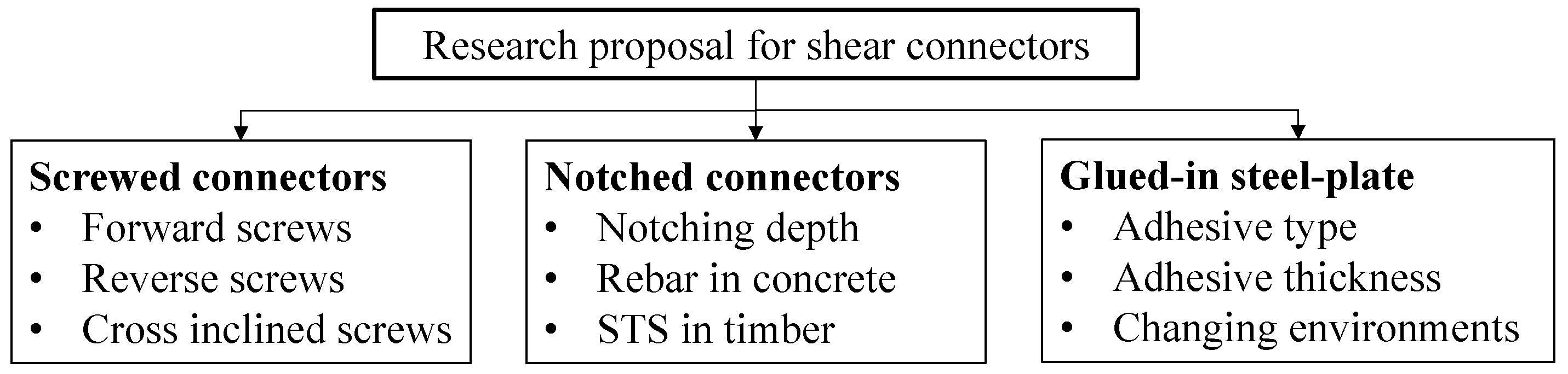
5.1. Shear Connectors

As summarized in Section 2, the existing research on shear connectors of TCC structures mainly considered the dowelled-type and notched-type connectors. It has been demonstrated that the interfacial long-term slip cannot be ignored. The service environments, component materials, and screw types are the main parameters considered in the existing long-term tests. Recently, some new discoveries in improving the short-term behavior of shear connectors have been obtained. However, limited to a long experimental period, the corresponding long-term experimental studies have not been reported in time. Figure 7 summarizes the research proposal for three typical shear connectors.
(1)
Screwed connectors
Inclined screwed connectors are characterized by high load-carrying capacities and slip moduli thanks to the contribution of the great pushout behavior of screws in tension [4,31,134]. Considering the reciprocating action of seismic load, it is necessary to arrange the reverse sheared screws or bi-directional sheared screws between the timber and concrete [135]. As listed in Table 1, most of the literature has focused on the long-term behaviors of vertical screw connectors. However, vertical screws showed a different anti-slip behavior compared with the screws both in tension and compression. Accordingly, long-term behaviors of screwed connectors should be explored, when screws are set to various inclination angles including the forward, reverse, and crossed inclined screws, as shown in Figure 7;
(2)
Notched connectors
Notched connectors have been a research hotspot in recent years due to the advantages of its high stiffness, sufficient strength, and low construction cost [136]. Existing studies [6,14,136,137,138] have demonstrated that the notching depth greatly affects the slip moduli, and increasing steel-bars in concrete and self-tapping screws in timber can improve the shear strength, slip modulus, and ductility of notched connectors. The long-term response of the notched connectors caused by the above factors needs to be further studied to provide accurate calculation guidance;
(3)
Glued-in steel-plate connectors
Glued-in steel-plate connectors are a type of relatively novel connectors used in TCC structures. As discussed in Section 2.3, none of the literature has reported on the long-term performance of such connectors as far as the author knows. Some scholars [47,61,139] reported the short- and long-term behaviors of pure adhesion connections in TCC structures and the bonding steel-plate or glued-in rebar joints used in timber ones. For glued-in steel-plate connectors, however, the long-term behavior still remains a research gap. The effects of adhesive types and thickness as well as the surrounding environments on the long-term slip of this type of shear connectors seem to be greatly significant.
Figure 7. Research proposal for three typical shear connectors.
Buildings 14 01770 g007

5.2. TCC Structures

The long-term behavior of TCC structures is determined by the creep of component materials (timber and concrete) and shear connectors under the action of sustained loads and ambient RH and temperature. Particularly, the creep of shear connectors is demonstrated and clearly recorded in the literature referenced in Section 3.1. The intrinsic relationship between the creep of connectors and the long-term performance of composite beams needs to be further studied.
(1)
Diversity of shear connectors reflected in TCC structures
Most numerical analyses summarized in Section 3.2 established the creep constitutive equation by considering the wood creep or a simple coupling of wood and concrete creeps, which failed to consider the connector types and structural dimension parameters of fasteners [117,125,128]. The diversity of shear connectors is recommended to be considered while analyzing the long-term behavior of TCC structures. On one hand, the creep constitutive of shear connectors can be obtained based on long-term push-out tests. On the other hand, numerical analysis on the long-term behavior of shear connectors also needs a comprehensive analysis by considering different connector types, fastener dimensions, loading levels, etc.;
(2)
Influence of environmental complexity on timber
As mentioned above, timber is accompanied with a fluctuating EMC under different environmental RH. Variable EMCs might lead to changes in both elastic modulus and mechano-sorptive creep. For TCC beams which are subjected to long-term load, their moisture-induced creep deformation has also been determined by the loading level. As soon as the loading level is less than 30% of short-term strength and the environmental condition is invariable, the mechano-sorptive behavior could be considered as linear-viscoelasticity, whereas in an uncontrolled environment, the behavior becomes nonlinear. Without accurate formulations to evaluate these parameters, the numerical methods cannot achieve reliable results. Thus, in numerical simulations, those parameters of creep behaviors beyond the range of elasticity and viscoelasticity need to be determined in the future. In addition, besides the effects of different tree species and size effects, the creep parameters reflected in new engineered wood products, such as CLT, NLT, and SLT [18,140,141,142,143] also require further exploration.

6. Conclusions

In this article, the state-of-the-art on the research on the long-term behavior of TCC structures mainly in terms of experimental and numerical analysis has been presented. By counting a total of 27 groups of shear connection specimens and about 50 (groups) TCC beam/floor specimens, the numerical constitutive relations for the timber, concrete, and shear connectors are illustrated, and the overall development of numerical analysis for the long-term behavior of TCC structures is presented. Finally, the calculation methods in some standards are introduced. Based on the review of the existing research, several suggestions are presented aiming to provide guidance for further research. The main conclusions are summarized as follows:
(1)
The long-term tests for shear connectors mainly focused on the dowelled- and notched-type connections. The long-term tests were commonly conducted under controlled environments. The creep coefficients were mainly affected by concrete types, connection types, loading levels, and duration;
(2)
The maximum creep coefficients of screwed and notched connectors in the limited loading duration were 1.80 and 4.275 according to existing reports. However, no correlation can be established between long-term experimental results from different studies due to the different connection configurations, materials, loading levels, etc.;
(3)
The long-term tests for TCC bending members were mainly conducted in uncontrolled environments. Connection types, component materials, and surrounding ambient environment are the main research parameters. Common connection types researched included screwed, notched, and adhesively bonded connections;
(4)
In numerical investigations and design specification, only the long-term creep characteristics of concrete and timber were considered. It was suggested that the long-term slip characteristic of shear connectors can be covered in the future investigations of TCC structures.
In general, a lot of valuable research on TCC structures has been carried out. However, limited to the complex creep characteristics of timber and shear connectors, as well as the emergence of new types of engineered timber, connectors, and timber reinforcement methods, the long-term behavior of TCC structures and related components still requires further study.
Table 5 lists the main acronyms used in this paper.

Author Contributions

Conceptualization, B.S.; methodology, B.S. and H.Y.; validation, X.Z. and H.T.; formal analysis, X.Z.; writing—original draft preparation, B.S. and X.Z.; writing—review and editing, H.T. and B.W.; supervision, H.Y.; project administration, B.S. and H.Y.; funding acquisition, B.S. and H.Y. All authors have read and agreed to the published version of the manuscript.

Funding

This research was funded by the National Natural Science Foundation of China, grant number 52208253 and 51878344.

Conflicts of Interest

The authors declare no conflicts of interest.

References

  1. Dias, A.; Skinner, J.; Crews, K.; Tannert, T. Timber-Concrete-Composites Increasing the Use of Timber in Construction. Eur. J. Wood Wood Prod. 2016, 74, 443–451. [Google Scholar] [CrossRef]
  2. Rodrigues, J.N.; Dias, A.M.P.G.; Providência, P. Timber-Concrete Composite Bridges: State-of-the-Art Review. Bioresources 2013, 8, 6630–6649. [Google Scholar] [CrossRef]
  3. Ling, Z.B.; Li, Z.; Lu, F.; Yang, H.F.; Zheng, W.; Zhang, L.F. Flexural Strengthening of Timber-Concrete Composite Beams Using Mechanically Fastened and Externally Bonded Combining Mechanically Fastened Strengthening Techniques. J. Build. Eng. 2023, 78, 107645. [Google Scholar] [CrossRef]
  4. Sebastian, W.M.; Piazza, M.; Harvey, T.; Webster, T. Forward and Reverse Shear Transfer in Beech LVL-Concrete Composites with Singly Inclined Coach Screw Connectors. Eng. Struct. 2018, 175, 231–244. [Google Scholar] [CrossRef]
  5. Derikvand, M.; Fink, G. Deconstructable Connector for TCC Floors Using Self-Tapping Screws. J. Build. Eng. 2021, 42, 102495. [Google Scholar] [CrossRef]
  6. Shi, B.K.; Dai, Y.Q.; Tao, H.T.; Yang, H.F. Shear Performances of Hybrid Notch-Screw Connections for Timber-Concrete Composite Structures. Bioresources 2022, 17, 2259–2274. [Google Scholar] [CrossRef]
  7. Jiang, Y.C.; Hu, X.M.; Hong, W.; Zhang, J.; He, F.Q. Experimental Study on Notched Connectors for Glulam-Lightweight Concrete Composite Beams. Bioresources 2020, 15, 2171–2180. [Google Scholar] [CrossRef]
  8. Yang, H.F.; Lu, Y.; Ling, X.; Tao, H.T.; Shi, B.K. Experimental and Theoretical Investigation on Shear Performances of Glued-in Perforated Steel Plate Connections for Prefabricated Timber–Concrete Composite Beams. Case Stud. Constr. Mat. 2023, 18, e01885. [Google Scholar] [CrossRef]
  9. Appavuravther, E.; Vandoren, B.; Henriques, J. Push-out Tests on Adhesively Bonded Perfobond Shear Connectors for Timber-Concrete Composite Beams. J. Build. Eng. 2022, 57, 104833. [Google Scholar] [CrossRef]
  10. Otero-Chans, D.; Estévez-Cimadevila, J.; Suárez-Riestra, F.; Martín-Gutiérrez, E. Experimental Analysis of Glued-in Steel Plates Used as Shear Connectors in Timber-Concrete-Composites. Eng. Struct. 2018, 170, 1–10. [Google Scholar] [CrossRef]
  11. Brunner, M.; Romer, M.; Schnüriger, M. Timber-Concrete-Composite with an Adhesive Connector (Wet on Wet Process). Mater. Struct. 2007, 40, 119–126. [Google Scholar] [CrossRef]
  12. Zhang, L.; Zhou, J.H.; Chui, Y.X.; Tomlinson, D. Experimental Investigation on the Structural Performance of Mass Timber Panel-Concrete Composite Floors with Notched Connections. J. Struct. Eng. 2022, 148, 04021249. [Google Scholar] [CrossRef]
  13. Mirdad, M.A.H.; Chui, Y.H. Strength Prediction of Mass-Timber Panel Concrete-Composite Connection with Inclined Screws and a Gap. J. Struct. Eng. 2020, 146, 04020140. [Google Scholar] [CrossRef]
  14. Zhang, L.; Chui, Y.H.; Tomlinson, D. Experimental Investigation on the Shear Properties of Notched Connections in Mass Timber Panel-Concrete Composite Floors. Constr. Build. Mater. 2020, 234, 117375. [Google Scholar] [CrossRef]
  15. Bao, Y.W.; Lu, W.D.; Yue, K.; Zhou, H.; Lu, B.H.; Chen, Z.T. Structural Performance of Cross-Laminated Timber-Concrete Composite Floors with Inclined Self-Tapping Screws Bearing Unidirectional Tension-Shear Loads. J. Build. Eng. 2022, 55, 104653. [Google Scholar] [CrossRef]
  16. Jiang, Y.C.; Crocetti, R. CLT-Concrete Composite Floors with Notched Shear Connectors. Constr. Build. Mater. 2019, 195, 127–139. [Google Scholar] [CrossRef]
  17. Crocetti, R.; Ekholm, K.; Kliger, R. Stress-Laminated-Timber Decks: State of the Art and Design Based on Swedish Practice. Eur. J. Wood Wood Prod. 2016, 74, 453–461. [Google Scholar] [CrossRef]
  18. Ben, Q.G.; Dai, Y.Q.; Chen, S.J.; Shi, B.K.; Yang, H.F. Shear Performances of Shallow Notch-Screw Connections for Timber-Concrete Composite (TCC) Floors. Bioresources 2022, 17, 3278–3290. [Google Scholar] [CrossRef]
  19. Khorsandnia, N.; Valipour, H.; Schaenzlin, J.; Crews, K. Experimental Investigations of Deconstructable Timber-Concrete Composite Beams. J. Struct. Eng. 2016, 142, 14016130. [Google Scholar] [CrossRef]
  20. Boccadoro, L.; Frangi, A. Experimental Analysis of the Structural Behavior of Timber-Concrete Composite Slabs Made of Beech-Laminated Veneer Lumber. J. Perform. Constr. Facil. 2014, 28, A4014006. [Google Scholar] [CrossRef]
  21. Chen, S.; Wei, Y.; Wang, G.F.; Zhao, K.; Yang, B. Experimental Investigation on Shear Behavior of Bamboo-Concrete Composite Structure with Perforated Steel Plate Connection. J. Build. Eng. 2023, 79, 107795. [Google Scholar] [CrossRef]
  22. Shan, B.; Wang, Z.Y.; Li, T.Y.; Xiao, Y. Experimental and Analytical Investigations on Short-Term Behavior of Glubam-Concrete Composite Beams. J. Struct. Eng. 2020, 146, 04019217. [Google Scholar] [CrossRef]
  23. Wen, B.; Tao, H.T.; Shi, B.K.; Yang, H.F. Dynamic properties of timber–concrete composite beams with crossed inclined coach screw connections: Experimental and theoretical investigations. Buildings 2023, 13, 2268. [Google Scholar] [CrossRef]
  24. Du, H.; Hu, X.M.; Xie, Z.; Meng, Y.F. Experimental and Analytical Investigation on Fire Resistance of Glulam-Concrete Composite Beams. J. Build. Eng. 2021, 44, 103244. [Google Scholar] [CrossRef]
  25. Xie, Z.; Hu, X.M.; Du, H.; Zhang, X.Y. Vibration Behavior of Timber-Concrete Composite Floors under Human-Induced Excitation. J. Build. Eng. 2020, 32, 101744. [Google Scholar] [CrossRef]
  26. Martins, C.; Santos, P.; Almeida, P.; Godinho, L.; Dias, A. Acoustic Performance of Timber and Timber-Concrete Floors. Constr. Build. Mater. 2015, 101, 684–691. [Google Scholar] [CrossRef]
  27. Fragiacomo, M.; Gregori, A.; Xue, J.J.; Demartino, C.; Toso, M. Timber-Concrete Composite Bridges: Three Case Studies. J. Traffic Transp. Eng. 2018, 5, 429–438. [Google Scholar] [CrossRef]
  28. Tao, H.T.; Yang, H.F.; Ju, G.Y.; Xu, J.W.; Shi, B.K. Effective Width of Timber-Concrete Composite Beams with Crossed Inclined Coach Screw Connections at the Serviceability State. Eng. Struct. 2022, 267, 114716. [Google Scholar] [CrossRef]
  29. Boccadoro, L.; Zweidler, S.; Steiger, R.; Frangi, A. Bending Tests on Timber-Concrete Composite Members Made of Beech Laminated Veneer Lumber with Notched Connection. Eng. Struct. 2017, 132, 14–28. [Google Scholar] [CrossRef]
  30. Tao, H.T.; Yang, H.F.; Zhang, J.; Ju, G.Y.; Xu, J.W.; Shi, B.K. Nonlinear Finite Element Analysis on Timber-Concrete Composite Beams. J. Build. Eng. 2022, 51, 104259. [Google Scholar] [CrossRef]
  31. Marchi, L.; Scotta, R.; Pozza, L. Experimental and Theoretical Evaluation of TCC Connections with Inclined Self-Tapping Screws. Mater. Struct. 2017, 50, 180. [Google Scholar] [CrossRef]
  32. Di, N.S.; Gregori, A.; Fragiacomo, M. Experimental and Numerical Investigations on Timber-Concrete Connections with Inclined Screws. Eng. Struct. 2020, 209, 109993. [Google Scholar] [CrossRef]
  33. Du, H.; Hu, X.M.; Sun, Z.X.; Meng, Y.F.; Han, G.H. Load carrying capacity of inclined crossing screws in glulam-concrete composite beam with an interlayer. Compos. Struct. 2020, 245, 112333. [Google Scholar] [CrossRef]
  34. Shi, B.K.; Liu, W.Q.; Yang, H.F.; Tao, H.T.; Wang, C.C. Experimental study on flexural behavior of timber-concrete composite beams with notch-screw connections. J. Build. Struct. 2021, 42, 104–113. (In Chinese) [Google Scholar]
  35. Zhang, L.; Zhou, J.H.; Chui, Y.H. Development of High-Performance Timber-Concrete Composite Floors with Reinforced Notched Connections. Structures 2022, 39, 945–957. [Google Scholar] [CrossRef]
  36. Cuerrier-Auclair, S. Design Guide for Timber-Concrete Composite Floors in Canada; FP Innovations, Montréal: Pointe-Claire, QC, Canada, 2020. [Google Scholar]
  37. Naud, N.; Sorelli, L.; Salenikovich, A.; Cuerrier-Auclair, S. Fostering Glulam-UHPFRC Composite Structures for Multi-Storey Buildings. Eng. Struct. 2019, 188, 406–417. [Google Scholar] [CrossRef]
  38. Emilio, M.G.; Estévez-Cimadevila, J.; Dolores, O.C.; Suárez-Riestra, F. Discontinuous π-form steel shear connectors in timber-concrete composites. An experimental approach. Eng. Struct. 2020, 216, 110719. [Google Scholar] [CrossRef]
  39. Wei, Y.; Wang, Z.Y.; Chen, S.; Zhao, K.; Zheng, K.Q. Structural Behavior of Prefabricated Bamboo-Lightweight Concrete Composite Beams with Perforated Steel Plate Connectors. Arch. Civ. Mech. Eng. 2021, 21, 15. [Google Scholar] [CrossRef]
  40. Tao, H.T.; Shi, B.K.; Yang, H.F.; Wang, C.C.; Ling, X.; Xu, J.W. Experimental and Finite Element Studies of Prefabricated Timber-Concrete Composite Structures with Glued Perforated Steel Plate Connections. Eng. Struct. 2022, 268, 114778. [Google Scholar] [CrossRef]
  41. Xu, Q.F.; Chen, L.Z.; Harries, K.A.; Zhang, F.W.; Wang, Z.L.; Chen, X. Experimental Study and Numerical Simulation of Long-Term Behavior of Timber Beams Strengthened with near Surface Mounted CFRP Bars. Mater. Struct. 2017, 50, 45. [Google Scholar] [CrossRef]
  42. Huang, Y.X. Creep Behavior of Wood under Cyclic Moisture Changes: Interaction between Load Effect and Moisture Effect. J. Wood. Sci. 2016, 62, 392–399. [Google Scholar] [CrossRef]
  43. Fragiacomo, M.; Joerg, S. Proposal to Account for Concrete Shrinkage and Environmental Strains in Design of Timber-Concrete Composite Beams. J. Struct. Eng. 2013, 139, 162–167. [Google Scholar] [CrossRef]
  44. Khorsandnia, N.; Valipour, H.R.; Crews, K. Experimental and Analytical Investigation of Short-Term Behaviour of LVL-Concrete Composite Connections and Beams. Constr. Build. Mater. 2012, 37, 229–238. [Google Scholar] [CrossRef]
  45. Yeoh, D.; Fragiacomo, M.; Franceschi, M.; Boon, K.H. State of the Art on Timber-Concrete Composite Structures: Literature Review. J. Struct. Eng. 2011, 137, 1085–1095. [Google Scholar] [CrossRef]
  46. Van de Kuilen, J.W.G. Creep of Timber Joints. Heron 2008, 53, 133–156. [Google Scholar]
  47. Shi, B.K.; Yang, H.F.; Liu, J.Z.; Crocetti, R.; Liu, W.Q. Short- and Long-Term Performance of Bonding Steel-Plate Joints for Timber Structures. Constr. Build. Mater. 2020, 240, 117945. [Google Scholar] [CrossRef]
  48. Van de Kuilen, J.W.G.; Dias, A. Long-Term Load-Deformation Behaviour of Timber-Concrete Joints. Proc. Inst. Civ. Eng. Struct. Build. 2011, 164, 141–154. [Google Scholar] [CrossRef]
  49. EN 1995-1-1:2009; Eurocode 5—Design of Timber Structures—Part 1-1: General-Common Rules and Rules for Buildings. European Committee for Standardization (CEN): Brussels, Belgium, 2009.
  50. Fragiacomo, M.; Amadio, C.; Macorini, L. Short- and Long-Term Performance of the “Tecnaria” Stud Connector for Timber-Concrete Composite Beams. Mater. Struct. 2007, 40, 1013–1026. [Google Scholar] [CrossRef]
  51. Jorge, L.F.; Schaenzlin, J.; Lopes, S.M.R.; Cruz, H.; Kuhlmann, U. Time-Dependent Behaviour of Timber Lightweight Concrete Composite Floors. Eng. Struct. 2010, 32, 3966–3973. [Google Scholar] [CrossRef]
  52. Fragiacomo, M. Experimental Behaviour of a Full-Scale Timber-Concrete Composite Floor with Mechanical Connectors. Mater. Struct. 2012, 45, 1717–1735. [Google Scholar] [CrossRef]
  53. Jiang, Y.C.; Hu, X.M.; Liu, Y.; Tao, L. Long-Term Performance of Glulam-Lightweight Concrete Composite Beams with Screw Connections. Constr. Build. Mater. 2021, 310, 125227. [Google Scholar] [CrossRef]
  54. Dias, A.; Cruz, H.; Lopes, S.; Van de Kuilen, J.W.G. Creep Effects in Timber Concrete Joints with Dowels and Notches. In Proceedings of the 9th World Conference on Timber Engineering, Portland, OR, USA, 6–10 August 2006. [Google Scholar]
  55. Dias, A. Mechanical Behaviour of Timber-Concrete Joints. Ph.D Thesis, Universidade de Coimbra, Coimbra, Portugal, 2005. [Google Scholar]
  56. Kuhlmann, U.; Michelfelder, B. Grooves as Shear-Connectors in Timber-Concrete Composite Structures. In Proceedings of the 8th World Conference on Timber Engineering, Lahti, Finland, 14–17 June 2004. [Google Scholar]
  57. Mueller, J.; Haedicke, W.; Simon, A.; Rautenstrauch, A. Long-Term Performance of Hybrid Timber Bridges–Experimental and Numerical Investigations. In Proceedings of the WCTE 2008-10th World Conference on Timber Engineering, Miyazaki, Japan, 2–5 June 2008. [Google Scholar]
  58. Shi, B.K.; Liu, W.Q.; Yang, H.F.; Ling, X. Long-term performance of timber-concrete composite systems with notch-screw connections. Eng. Struct. 2020, 213, 110585. [Google Scholar] [CrossRef]
  59. Shi, B.K. Long-term Behaviour of Prefabricated Timber-Concrete Composite Beams. Ph.D Thesis, Southeast University, Nanjing, China, 2021. [Google Scholar]
  60. Shi, B.K.; Yang, H.F.; Cao, H.; Xiao, K. Push-out tests of timber-concrete composite beams with steel plate-steel tube hybrid interfacial connections. J. Nanjing Tech Univ. (Nat. Sci. Ed.) 2021, 43, 390–398. (In Chinese) [Google Scholar]
  61. Eisenhut, L.; Seim, W.; Kühlborn, W. Adhesive-Bonded Timber-Concrete Composites—Experimental and Numerical Investigation of Hygrothermal Effects. Eng. Struct. 2016, 125, 167–178. [Google Scholar] [CrossRef]
  62. Lartigau, J.; Coureau, J.L.; Morel, S.; Galimard, P.; Maurin, E. Effect of Temperature on the Mechanical Performance of Glued-in Rods in Timber Structures. Int. J. Adhes. Adhes. 2015, 57, 79–84. [Google Scholar] [CrossRef]
  63. Verdet, M.; Coureau, J.L.; Cointe, A.; Salenikovich, A.; Galimard, P.; Delisee, C.; Toro, W.M. Creep Performance of Glued-in Rod Joints in Controlled and Variable Climate Conditions. Int. J. Adhes. Adhes. 2017, 75, 47–56. [Google Scholar] [CrossRef]
  64. Cavalli, A.; Malavolti, M.; Morosini, A.; Salvini, A.; Togni, M. Mechanical Performance of Full Scale Steel-Timber Epoxy Joints after Exposure to Extreme Environmental Conditions. Int. J. Adhes. Adhes. 2014, 54, 86–92. [Google Scholar] [CrossRef]
  65. Larsson, G.; Gustafsson, P.J.; Serrano, E.; Crocetti, R. Duration of Load Behaviour of a Glued Shear Plate Dowel Joint. Eur. J. Wood Wood Prod. 2020, 78, 5–15. [Google Scholar] [CrossRef]
  66. Chiniforush, A.A.; Valipour, H.R.; Bradford, M.A.; Akbarnezhad, A. Long-Term Behaviour of Steel-Timber Composite (STC) Shear Connections. Eng. Struct. 2019, 196, 109356. [Google Scholar] [CrossRef]
  67. Fragiacomo, M.; Batchelar, M. Timber Frame Moment Joints with Glued-in Steel Rods: Experimental Investigation of Long-Term Performance. J. Struct. Eng. 2012, 138, 802–811. [Google Scholar] [CrossRef]
  68. Zheng, X.Z.; Li, Z.; He, M.J.; Lam, F. Experimental Investigation on the Rheological Behavior of Timber in Longitudinal and Transverse Compression. Constr. Build. Mater. 2021, 304, 124633. [Google Scholar] [CrossRef]
  69. Li, Z.; Zheng, X.Z.; He, M.J.; Sun, Y.L.; He, G.R. Experimental and Analytical Investigations into the Time-Dependent Performance in Post-Tensioned Timber Beam-Column Joints under Sustained Loads and Varied Environment. Constr. Build. Mater. 2020, 251, 118943. [Google Scholar] [CrossRef]
  70. Zheng, X.Z.; He, M.J.; Lam, F.; Sun, Y.L.; Liang, F.; Li, Z. Experimental and Numerical Investigation of Long-Term Loss of Prestressing Force in Posttensioned Timber Joints with Different Structural Details. J. Struct. Eng. 2022, 148, 04022124. [Google Scholar] [CrossRef]
  71. Zheng, X.Z.; Lam, F.; Li, Z.; He, M.J. Long-Term Performance Assessment of Post-Tensioned Timber Connections under Different Climates. Constr. Build. Mater. 2023, 368, 130360. [Google Scholar] [CrossRef]
  72. Ceccotti, A.; Fragiacomo, M.; Giordano, S. Long-Term and Collapse Tests on a Timber-Concrete Composite Beam with Glued-in Connection. Mater. Struct. 2007, 40, 15–25. [Google Scholar] [CrossRef]
  73. Bathon, L.; Bletz, O.; Bahmer, R. Long Term Performance of Continuous Wood-Concrete composite Systems. In Proceedings of the 10th World Conference on Timber Engineering, Portland, OR, USA, 6–10 August 2006. [Google Scholar]
  74. Fragiacomo, M.; Gutkowski, R.M.; Balogh, J.; Fast, R.S. Long-Term Behavior of Wood-Concrete Composite Floor/Deck Systems with Shear Key Connection Detail. J. Struct. Eng. 2007, 133, 1307–1315. [Google Scholar] [CrossRef]
  75. To, L.; Fragiacomo, M.; Balogh, J.; Gutkowski, R.M. Long-Term Load Test of a Wood-Concrete Composite Beam. Proc. Inst. Civ. Eng. Struct. Build. 2011, 164, 155–163. [Google Scholar] [CrossRef]
  76. Gutkowski, R.M.; Miller, N.J.; Fragiacomo, M.; Balogh, J. Composite Wood-Concrete Beams Using Utility Poles: Time-Dependent Behavior. J. Struct. Eng. 2011, 137, 625–634. [Google Scholar] [CrossRef]
  77. Yeoh, D.; Fragiacomo, M.; Deam, B. Long-Term Performance of LVL-Concrete Composite Beams under Service Load. In Proceedings of the WCTE—World Conference on Timber Engineering, Auckland, New Zealand, 15–19 July 2012. [Google Scholar]
  78. Yeoh, D.; Boon, K.H.; Loon, L.Y. Timber-Concrete Composite Floor Beams under 4 Years Long-Term Load. Int. J. Integr. Eng. 2013, 5, 1–7. [Google Scholar]
  79. Fragiacomo, M.; Lukaszewska, E. Development of Prefabricated Timber-Concrete Composite Floor Systems. Proc. Inst. Civ. Eng. Struct. Build. 2011, 164, 117–129. [Google Scholar] [CrossRef]
  80. Fragiacomo, M.; Lukaszewska, E. Time-Dependent Behaviour of Timber-Concrete Composite Floors with Prefabricated Concrete Slabs. Eng. Struct. 2013, 52, 687–696. [Google Scholar] [CrossRef]
  81. Hailu, M. Long-Term Performance of Timber-Concrete Composite Flooring Systems. Ph.D. Thesis, University of Technology Sydney, Sydney, Australia, 2015. [Google Scholar]
  82. Eisenhut, L.; Seim, W. Long-term Behavior of Glued Full-Scale Specimens Made from Wood and High Performance Concrete at Natural Climate Conditions. Bautechnik 2016, 93, 807–816. [Google Scholar] [CrossRef]
  83. Tannert, T.; Endacott, B.; Brunner, M.; Vallee, T. Long-term performance of adhesively bonded timber-concrete composites. Int. J. Adhes. Adhes. 2017, 72, 51–61. [Google Scholar] [CrossRef]
  84. Czabak, M.; Perkowski, Z. Experimental Investigations of Wooden and Concrete Composite Beams Subject to Long-Term Load. MATEC Web Conf. 2018, 174, 01016. [Google Scholar] [CrossRef]
  85. Kanocz, J.; Bajzecerova, V.; Steller, S. Timber- Concrete Composite Elements with Various Composite Connections Part 1: Screwed Connection. Wood Res. 2013, 58, 555–570. [Google Scholar]
  86. Kanocz, J.; Bajzecerova, V.; Steller, S. Timber—Concrete Composite Elements with Various Composite Connections Part 2: Grooved Connection. Wood Res. 2014, 59, 627–638. [Google Scholar]
  87. Kanocz, J.; Bajzecerova, V. Timber—Concrete Composite Elements with Various Composite Connections Part 3: Adhesive Connection. Wood Res. 2015, 60, 939–952. [Google Scholar]
  88. Bajzecerova, V.; Kanocz, J. The Effect of Environment on Timber-Concrete Composite Bridge Deck. Procedia Eng. 2016, 156, 32–39. [Google Scholar] [CrossRef]
  89. Kong, K.; Ferrier, E.; Michel, L.; Agbossou, A. Experimental and Analytical Study of the Mechanical Behavior of Heterogeneous Glulam-Uhpfrc Beams Assembled by Bonding: Short- and Long-Term Investigations. Constr. Build. Mater. 2015, 100, 136–148. [Google Scholar] [CrossRef]
  90. Augeard, E.; Ferrier, E.; Michel, L. Mechanical Behavior of Timber-Concrete Composite Members under Cyclic Loading and Creep. Eng. Struct. 2020, 210, 110289. [Google Scholar] [CrossRef]
  91. Hwang, S.W.; Chung, H.; Lee, T. Dimensional Behavior of Nail-Laminated Timber-Concrete Composite Caused by Changes in Ambient Air, and Correlation among Temperature, Relative Humidity, and Strain. Bioresources 2023, 18, 1637–1652. [Google Scholar] [CrossRef]
  92. Shi, B.K.; Liu, W.Q.; Yang, H.F. Experimental investigation on the long-term behaviour of prefabricated timber-concrete composite beams with steel plate connections. Constr. Build. Mater. 2021, 266, 120892. [Google Scholar] [CrossRef] [PubMed]
  93. Derikvand, M.; Kotlarewski, N.; Lee, M.; Jiao, H.; Chan, A.; Nolan, G. Short-Term and Long-Term Bending Properties of Nail-Laminated Timber Constructed of Fast-Grown Plantation Eucalypt. Constr. Build. Mater. 2019, 211, 952–964. [Google Scholar] [CrossRef]
  94. Chiniforush, A.A.; Valipour, H.R.; Bradford, M.A.; Nezhad, A.A. Experimental and Theoretical Investigation of Long-Term Performance of Steel-Timber Composite Beams. Eng. Struct. 2021, 249, 113314. [Google Scholar] [CrossRef]
  95. Bajzecerová, V.; Kanócz, J.; Rovňák, M.; Kováč, M. Prestressed CLT-concrete composite panels with adhesive shear connection. J. Build. Eng. 2022, 56, 104785. [Google Scholar] [CrossRef]
  96. Riccadonna, D.; Walsh, K.; Schiro, G.; Piazza, M.; Giongo, I. Testing of long-term behaviour of pre-stressed timber-to-timber composite (TTC) floors. Constr. Build. Mater. 2020, 236, 117596. [Google Scholar] [CrossRef]
  97. Avramidis, S.T.; Siau, J.F. An Investigation of the External and Internal Resistance to Moisture Diffusion in Wood. Wood Sci. Technol. 1987, 21, 249–256. [Google Scholar] [CrossRef]
  98. Franke, B.; Franke, S.; Müller, A.; Schiere, M. Long-Term Behaviour of Moisture Content in Timber Constructions–Relation to Service Classes. Int. Netw. Timber Eng. Res. Meet. Forty-Nine 2016, 5, 19–23. [Google Scholar]
  99. EN 384:2004; Structural Timber—Determination of Characteristic Values of Mechanical Properties and Density. European Committee for Standardization: Brussels, Belgium, 2004.
  100. Gülzow, A.; Richter, K.; Steiger, R. Influence of Wood Moisture Content on Bending and Shear Stiffness of Cross Laminated Timber Panels. Eur. J. Wood Wood Prod. 2011, 69, 193–197. [Google Scholar] [CrossRef]
  101. Bažant, Z.P. Constitutive Equation of Wood at Variable Humidity and Temperature. Wood Sci. Technol. 1985, 19, 159–177. [Google Scholar] [CrossRef]
  102. Ranta-Maunus, A. The Viscoelasticity of Wood at Varying Moisture Content. Wood Sci. Technol. 1975, 9, 189–205. [Google Scholar] [CrossRef]
  103. Toratti, T. Modelling the Creep of Timber Beams. Raken. Mek. 1992, 25, 12–35. [Google Scholar]
  104. Fragiacomo, M.; Ceccotti, A. Long-term behavior of timber–concrete composite beams. I: Finite element modeling and validation. J. Struct. Eng. 2006, 132, 13–22. [Google Scholar] [CrossRef]
  105. Fragiacomo, M. Long-term behavior of timber–concrete composite beams. II: Numerical analysis and simplified evaluation. J. Struct. Eng. 2006, 132, 23–33. [Google Scholar] [CrossRef]
  106. Morlier, P. Creep in Timber Structures; Taylor & Francis Group: Bordeax, France, 1994. [Google Scholar]
  107. Schänzlin, J. Modeling the Long-Term Behavior of Structural Timber for Typical Serviceclass-II-Conditions in South-West Germany. Ph.D Thesis, University of Stuttgart, Stuttgart, Germany, 2010. [Google Scholar]
  108. Mackenzie-Helnwein, P.; Hanhijärvi, A. Computational analysis of quality reduction during drying of lumber due to irrecoverable deformation. I: Orthotropic viscoelastic-mechanosorptive-plastic material model for the transverse plane of wood. J. Eng. Mech. 2003, 129, 996–1005. [Google Scholar] [CrossRef]
  109. Malvern, L.E. Introduction to the Mechanics of a Continuous Medium; Prentice-Hall: Englewood Chffs, NJ, USA, 1969. [Google Scholar]
  110. Armstrong, L.D.; Christensen, G.N. Influence of moisture changes on deformation of wood under stress. Nature 1961, 191, 869–870. [Google Scholar] [CrossRef]
  111. Hoffmeyer, P.; Davidson, R.W. Mechano-sorptive creep mechanism of wood in compression and bending. Wood Sci. Technol. 1989, 23, 215–227. [Google Scholar] [CrossRef]
  112. Hanhijärvi, A.; Hunt, D. Experimental indication of interaction between viscoelastic and mechano-sorptive creep. Wood Sci. Technol. 1998, 32, 57–70. [Google Scholar] [CrossRef]
  113. Hunt, D. Linearity and non-linearity in mechano-sorptive creep of softwood in compression and bending. Wood Sci. Technol. 1989, 23, 323–333. [Google Scholar] [CrossRef]
  114. Montero, C.; Gril, J.; Legeas, C.; Hunt, D.G.; Clair, B. Influence of hygromechanical history on the longitudinal mechanosorptive creep of wood. Holzforschung 2012, 66, 757–764. [Google Scholar] [CrossRef]
  115. Toratti, T. Long-term deflection of timber beams. Raken. Mek. 1993, 26, 19–28. [Google Scholar]
  116. Mohager, S.; Toratti, T. Long term bending creep of wood in cyclic relative humidity. Wood Sci. Technol. 1992, 27, 49–59. [Google Scholar] [CrossRef]
  117. Khorsandnia, N.; Schänzlin, J.; Valipour, H.; Crews, K. Coupled finite element-finite difference formulation for long-term analysis of timber–concrete composite structures. Eng. Struct. 2015, 96, 139–152. [Google Scholar] [CrossRef]
  118. Svensson, S.; Toratti, T. Mechanical response of wood perpendicular to grain when subjected to changes of humidity. Wood Sci. Technol. 2002, 36, 145–156. [Google Scholar] [CrossRef]
  119. Fortino, S.; Mirianon, F.; Toratti, T. A 3D moisture-stress FEM analysis for time dependent problems in timber structures. Mech. Time-Depend. Mater. 2009, 13, 333–356. [Google Scholar] [CrossRef]
  120. ACI Committee. Building Code Requirements for Structural Concrete and Commentary (ACI 318-19); American Concrete Institute Committee: Farmington Hills, MI, USA, 2019. [Google Scholar]
  121. CEB-FIP. CEP-FIP Model Code for Concrete Structures; CEB-FIP: Lausanne, Switzerland, 2010. [Google Scholar]
  122. EN 1992-1-1:2004; Eurocode 2: Design of Concrete Structures-Part 1-1: General—Common Rules and Rules for Buildings. Comité Européen de Normalization: Brussel, Belguim, 2004.
  123. Amadio, C.; Di Marco, R.; Fragiacomo, M. A Linear Finite Element Model to Study Creep and Shrinkage Effects in a Timber-Concrete Composite Beam with Deformable Connections. In Proceedings of the RILEM Symposium on Timber Engineering, Stockholm, Sweden, 13–14 September 1999; pp. 747–756. [Google Scholar]
  124. Amadio, C.; Ceccotti, A.; Di Marco, R.; Fragiacomo, M. Numerical Evaluation of Long-Term Behaviour of Timber-Concrete Composite Beams. In Proceedings of the World Conference on Timber Engineering, Whistler Resort, BC, Canada, 31 July–3 August 2000. [Google Scholar]
  125. Fragiacomo, M.; Amadio, C.; Macorini, L. Finite-Element Model for Collapse and Long-Term Analysis of Steel–Concrete Composite Beams. J. Struct. Eng. 2004, 130, 489–497. [Google Scholar] [CrossRef]
  126. Khorsandnia, N.; Schänzlin, J.; Valipour, H.; Crews, K. Time-Dependent Behaviour of Timber–Concrete Composite Members: Numerical Verification, Sensitivity and Influence of Material Properties. Constr. Build. Mater. 2014, 66, 192–208. [Google Scholar] [CrossRef]
  127. Fragiacomo, M.; Fortino, S.; Tononi, D.; Usardi, I.; Toratti, T. Moisture-Induced Stresses Perpendicular to Grain in Cross-Sections of Timber Members Exposed to Different Climates. Eng. Struct. 2011, 33, 3071–3078. [Google Scholar] [CrossRef]
  128. Fragiacomo, M.; Lukaszewska, E. Influence of the Construction Method on the Long-Term Behavior of Timber-Concrete Composite Beams. J. Struct. Eng. 2015, 141, 04015013. [Google Scholar] [CrossRef]
  129. Fragiacomo, M.; Balogh, J.; To, L.; Gutkowski, R.M. Three-Dimensional Modeling of Long-Term Structural Behavior of Wood-Concrete Composite Beams. J. Struct. Eng. 2014, 140, A4014006. [Google Scholar] [CrossRef]
  130. Binder, E.; Derkowski, W.; Bader, T.K. Hybrid Modeling Approach for Time-Dependent Behavior of Timber-Concrete-Composite Structures. In Proceedings of the FIB International Congress 2022, Oslo, Norway, 12–16 June 2022. [Google Scholar]
  131. AWC/ANSI. National Design Specifications for Wood Construction, 2018 Edition; American Wood Council: Leesburg, VA. USA, 2018. [Google Scholar]
  132. AWC. Manul for Engineering Wood Construction, 2018 Edition; American Wood Council: Leesburg, VA, USA, 2018. [Google Scholar]
  133. AS/NZS. Structureal Design Actions Part 1: Permanent, Imposde and Other Actions; Standards Australia: Sydney, Australia, 2002. [Google Scholar]
  134. Tao, H.T.; Yang, H.F.; Liu, W.Q.; Wang, C.C.; Shi, B.K.; Ling, X. Experimental and Nonlinear Analytical Studies on Prefabricated Timber–Concrete Composite Structures with Crossed Inclined Coach Screw Connections. J. Struct. Eng. 2021, 147, 04021043. [Google Scholar] [CrossRef]
  135. Tao, H.T.; Yang, H.F.; Liu, W.Q.; Wang, C.C.; Shi, B.K.; Ling, X. Mechanical behavior of crossed inclined coach screw shear connections for prefabricated timber-concrete composite structures. J. Build. Struct. 2022, 43, 164–174. (In Chinese) [Google Scholar]
  136. Rasmussen, P.K.; Sørensen, J.H.; Hoang, L.C.; Feddersen, B.; Larsen, F. Notched connection in timber-concrete composite deck structures: A literature review on push-out experiments & design approaches. Constr. Build. Mater. 2023, 397, 131761. [Google Scholar]
  137. Yang, M.B. Investigations on Notch-Screw Connection of Timber-Lightweight Aggregate Concrete. Master’s Thesis, Nanjing Tech University, Nanjing, China, 2022. [Google Scholar]
  138. Huang, B.W. Investigations on Flexural Behavior of Timber-Lightweight Concrete Composite Beams. Master’s Thesis, Nanjing Tech University, Nanjing, China, 2022. [Google Scholar]
  139. Schober, K.U.; Tannet, T. Hybrid connections for timber structures. Eur. J. Wood Prod. 2016, 74, 369–377. [Google Scholar] [CrossRef]
  140. Siddika, A.; Mamun, M.A.A.; Aslani, F.; Zhuge, Y.; Alyousef, R.; Hajimohammadi, A. Cross-laminated timber–concrete composite structural floor system: A state-of-the-art review. Eng. Fail. Anal. 2021, 130, 105766. [Google Scholar] [CrossRef]
  141. Ben, Q.G.; Zhang, C.C.; Shi, B.K.; Yang, H.F. Experimental Evaluation of Flexural Behavior of Stress Laminated Timber Decks. J. Renew. Mater. 2022, 10, 3599–3610. [Google Scholar] [CrossRef]
  142. Binder, E.; Derkowski, W.; Bader, T.K. Development of Creep Deformations During Service Life: A Comparison of CLT and TCC Floor Constructions. Buildings 2022, 12, 239. [Google Scholar] [CrossRef]
  143. Gan, Z.Z.; Sun, Y.L.; Sun, X.F.; Zhou, L.N.; He, M.J. Push-out performance of inclined screw shear connectors used in nail-laminated timber-concrete composite. Constr. Build. Mater. 2023, 366, 130175. [Google Scholar] [CrossRef]
Figure 1. Diagrams of the TCC floor: (a) with timber beams and (b) with a timber slab.
Buildings 14 01770 g001
Figure 2. Connection configuration: (a) dowels; (b) dowels with an interlayer; (c) Tecnaria connector; (d) inclined screw; (e) coach screw; (f) notched connector; (g) notch with coach screw; (h) notch with STS; (i) X-connector; (j) bonding; (k) bonding; and (l) steel plate connector.
Buildings 14 01770 g002aBuildings 14 01770 g002b
Figure 3. Self-tapping screw, VB-48-7.5×100 (dimensions in mm) [51].
Buildings 14 01770 g003
Figure 5. Steel-timber shear connectors reported by Chiniforush et al. [66]: (a) coach screw or dog screw; (b) post-tensioned bolt; and (c) bolt in grout pocket.
Buildings 14 01770 g005
Figure 6. Typical loading schemes: (a) continuous distributed loads adopted by Derikvand et al. [93]; (b) discontinuous distributed loads adopted by Hailu [81]; and (c) two concentrated loads adopted by Augeard et al. [90] and Bajzecerová et al. [95].
Buildings 14 01770 g006
Table 2. Long-term tests performed on TCC structures.
ReferencesConnectorTimberConcrete Loading LevelEnvironmentPeriodDeflection/Creep Coefficient a
Ceccotti et al. [72]Glued-in rebarGlulamC30/3511.1% (4 kN/m)Outdoor5 years3.36 mm
Bathon and Bletz [73]Glued-in steel meshGlulamNC35.4%Outdoor, sheltered430 days46.3 mm/1.4
Fragiacomo et al. [74]Shear key/anchor Glulam slab30.5 MPa12.5%, unshoredIndoor133 days4.87 mm/0.54
12.5%, shored4.62 mm/0.56
To et al. [75]Shear key/anchorNLT15.9 MPa2P = 2.526 kNOpened door123 daysAbout 21 mm
Gutkowski et al. [76]Shear key/anchorWood poles22.6 MPa11.1%Indoor228 days10.4 mm
Yeoh et al. [77,78]Notched-screwLVL35 MPa2.2 kN/m2Indoor4 years24.0 mm/3.94
LSC b29.9 mm/3.77
Tooth metal plate25.5 mm/3.28
Fragiacono and Lukaszewska [79,80]Steel-plate + screwsGlulamC20/2513%Indoor339 days5.62 mm
Coach screw5.28 mm
Hailu [81]Wood screwLVL32 MPa1.05 kN/m
(43% of design load)
20 °C
Changing RH
550 daysAbout 9.0
4 Bird’s-mouth notchesAbout 6.0
6 Bird’s-mouth notches1400 days7.7
Crossed STS7.9
Eisehut et al. [61,82]Epoxy—Sikadur 330Glulam HPC10.5 kNOutdoor2 years1.75–2.24
Epoxy—Hilti Hit-RE 5009.5 kN
Tannert et al. [83]Epoxy, 55% bonding areaGlulam slabC25/3030%Indoor4.5 years14.9 mm/0.90
Epoxy, 87% bonding area9.4 mm/0.76
Czabak [84]ScrewRaw wood42 MPa15%Indoor2 yearsAbout 20 mm
Kanócz et al. [85,86,87,88]Inclined screwWood planksC25/302P = 2 kNIndoor4.5 years8.42 mm/3.3
NotchedNLTC25/302P = 4 kN5 years2.94 mm/5.3
Epoxy—Sikadur T35 LVPGlulam slabLC20/222P = 6 kN2 years12.5 mm/1.3
Kong et al. [89]Glulam beam18 kN, 32%Indoor1 year0.2
Epoxy—Sikadur 31DWGlulamUHPFRC24 kN, 18%0.4
45 kN, 35%OutdoorDebonding on the 190th day
Augeard et al. [90]Epoxy—Eponal 371 V1GlulamC40/50Cycle loadsIndoor106 cycles0.17 (Average)
Jiang et al. [53]Coach screwsGlulamC303.5 kN/m2Indoor365 days3.36 mm/1.26
LC303.40 mm/1.20
5.84 mm/1.65 c
Outdoor, sheltered6.95 mm/2.47
Hwang [91]NotchedNLT24 MPa-Outdoor, sheltered145 days1.46% in height
Shi et al. [58,92]Glulam beam18.2 kN, 18.8%Indoor407 days4.25 mm/0.50
NotchedGlulamC30/3524.0 kN, 18.8% 4.20 mm/0.88
Steel-plate + screws20% 613 days6.56 mm/1.14
20% 5.79 mm/0.93 d
10%4.06 mm/1.40
Derikvand et al. [93]NLT panel, higher-grade, 3600 mm length4 kN/m2In door90 days0.29
NLT panel, lower-grade, 2600 mm length0.59
NLT panel, higher-grade, 2600 mm length0.51
Chiniforush et al. [94]Coach screwCLTSteel beam40%In door22 months0.15
Dog screw0.19
Post-tensioned bolt0.12
Coach screw + gout pocket0.19
CLT e0.10
CLT60%0.18
Bajzecerová et al. [95]Epoxy—Sikadur @32CLT41.1 MPa2P = 6.64 kNIndoor60 daysAbout 10.1 mm
30 daysAbout 9.4 mm
Note: a In the column, the values with length units in mm denote the deflection increment, while the dimensionless values denote the creep coefficient calculated with the method similar to Equation (1); b LSC denotes the low shrinkage concrete; c the screw distance in this specimen was 400 mm, while that in other specimens was 250 mm; d the connector quantity in this specimen was six while that in other ones was eight; e the CLT was perpendicularly arranged on the top of the steel beam.
Table 3. Characteristics of Kelvin type bodies for viscoelastic creep.
No.Shi et al. [47]Toratti [103]Schänzlin [107]
τi (day)Jiτi (day)Jiτi (day)Ji
10.010.07960.010.06760.010.0686
20.10.07950.1−0.00180.1−0.056
310.000010.062610.716
4100.1893100.0683100.409
51000.40021000.14271930.2201
610000.169350000.837311,0781.8052
Table 5. The table of acronyms.
AcronymMeaning
TCCTimber–concrete composite
CLTCross-laminated timber
SLTStressed-laminated timber
NLTNailed laminated timber
LVLLaminated veneer lumber
RHRelative humidity
NCNormal weight concrete
LWACLight-weight aggregate concrete
STSSelf-taping screw
OSBOriented strand board
HPCHigh-performance concrete
PURPolyurethane
CSCoach screw
DSDog screw
PBPost-tensioned bolt
BGPBolt in grout pocket
LSCLow shrinkage concrete
CFPRCarbon fiber-reinforced polymer rebar
UHPFRCUltra-high-performance fiber-reinforcement concrete
MCMoisture content
EMCEquilibrium moisture content
FSPFiber saturation point
FEFinite element
UMATUser’s defined material
SLSServiceability limit state
DLTDowelled laminated timber
Disclaimer/Publisher’s Note: The statements, opinions and data contained in all publications are solely those of the individual author(s) and contributor(s) and not of MDPI and/or the editor(s). MDPI and/or the editor(s) disclaim responsibility for any injury to people or property resulting from any ideas, methods, instructions or products referred to in the content.

