Article

Effect of Bidirectional Hysteretic Dampers on the Seismic Performance of Skewed Multi-Span Highway Bridges

1
Departamento de Obras Civiles, Universidad Técnica Federico Santa María, Valparaíso 2390123, Chile
2
Department of Civil Engineering, University of Chile, Santiago 8370449, Chile
3
Facultad de Ingeniería y Ciencias Aplicadas, Universidad de los Andes, Santiago 7620086, Chile
*
Author to whom correspondence should be addressed.
Buildings 2024, 14(6), 1778; https://doi.org/10.3390/buildings14061778
Submission received: 6 May 2024 / Revised: 31 May 2024 / Accepted: 4 June 2024 / Published: 13 June 2024
(This article belongs to the Special Issue Recent Study on Seismic Performance of Building Structures)

Abstract

:
Bridges are one of the most critical and costly structures on road networks. Thus, their integrity and operation must be preserved to prevent safety concerns and connectivity losses after seismic events. Recent large-magnitude earthquakes have revealed a series of vulnerabilities in multi-span highway bridges. In particular, skewed bridges have been severely damaged due to their susceptibility to developing excessive in-plane deck rotations and span unseating. Although seismic design codes have been updated to prescribe larger seating lengths and have incorporated unseating prevention devices, such as shear keys and cable restrainers, research on the seismic performance of skewed bridges with passive energy-dissipation devices is still limited. Therefore, this study focuses on assessing the effectiveness of implementing hysteretic dampers on skewed bridges. With that aim, dampers with and without recentering capabilities are designed and incorporated in representative Chilean skewed bridges to assess their contribution to seismic performance. Three-dimensional nonlinear finite element models, multiple-stripe analysis, and fragility curves are utilized to achieve this objective. The results show that incorporating bidirectional dampers can effectively improve the seismic performance of skewed bridges at different hazard levels by limiting in-plane deck rotations independently of their skew angle. Additionally, the influence of external shear keys and damper hysteretic behavior is analyzed, showing that these parameters have a low influence on bridge performance when bidirectional dampers are incorporated.

1. Introduction

The seismic vulnerability of skewed bridges has been clearly observed during previous moderate- and large-magnitude earthquakes, such as the 1971 Mw6.6 San Fernando earthquake [1,2] and the 1994 Mw6.7 Northridge earthquake [3] in the United States, the 2008 Mw7.9 Wenchuan earthquake in China [4,5], and the 2010 Mw8.8 Maule earthquake in Chile [6,7]. During the latter, a significant number of multi-span girder bridges supported on elastomeric bearings suffered extensive damage and even collapsed, causing significant downtime in the highway network and economic losses to the country [6,8]. The main deficiency identified after the Maule earthquake was the lack of devices that could restrain the horizontal displacement of the superstructure [6,7]. Therefore, many skewed bridges developed excessive deck displacements and rotations relative to the substructure, which, in the absence of adequate lateral restraint, caused span unseating [7]. The seismic behavior of skewed bridges has also been analyzed in analytical and experimental studies [9,10,11,12].
After the 2010 Maule earthquake, the Chilean Bridge Design Manual (BDM) [13] was revised, stating that new multi-span girder bridges must have internal reinforced concrete (RC) shear keys, diaphragms, anchored (i.e., bonded) laminated elastomeric bearings, and vertical seismic bars. In this context, the Chilean BDM also suggests the use of semi-integral and integral bridges for bridges up to 4 spans to improve deck continuity, reduce bearing maintenance, and prevent span unseating. Previous research has shown that repair measures (e.g., interior RC shear keys) considered for damaged bridges, which reflect changes in the BDM [13], can effectively decrease the probability of collapse at high levels of seismic intensity [14,15]. However, the influence of RC shear keys on preventing the loss of bridge serviceability and operation at lower ground-motion intensity levels has not yet been extensively studied. A few current bridge design codes or manuals (e.g., in Chile [13] and the USA [16]) base their seismic design philosophy on three performance criteria: (1) structures should resist without damage (i.e., perform in the elastic range) earthquakes of small to moderate intensity, (2) bridges should have limited non-structural damage during higher-intensity earthquakes, and (3) bridges may suffer extensive damage, but their total or partial collapse must be prevented during earthquakes of exceptionally severe intensity. Although the Chilean BDM [13] states these three seismic performance objectives, it does not provide specific seismic hazard levels or maps to determine the demands for seismic events of different intensity levels, and the design is only carried out and explicitly checked for one performance level, which is collapse prevention. Moreover, past earthquakes (e.g., the 2010 Mw8.8 Maule earthquake) have shown that the above performance objectives were not fulfilled. This represents a significant drawback when considering critical or essential bridges that, given their importance within the highway network, should remain fully operational after a seismic event. To achieve adequate performance objectives, we propose and assess the incorporation of bidirectional passive energy-dissipation systems (i.e., hysteretic dampers with and without recentering capabilities). In this context, hysteretic dampers are proposed to replace internal RC shear keys typically found in Chilean skewed multi-span girder bridges built before and after the 2010 Maule earthquake, as shown in Figure 1. External shear keys are still considered for bridges with hysteretic dampers, and their influence is presented later in this paper.
Energy-dissipation devices work as structural fuses, concentrating the seismic damage and maintaining the main structural components with minor or no damage. Although several studies have been carried out to evaluate the seismic performance of bridges with hysteretic dampers, they have been focused on unidirectional hysteretic dampers applied only in the transverse direction [17,18], which in practice can be materialized as metallic dampers, such as X-shaped steel dampers [19], buckling-restrained braces [20,21,22,23,24,25], or pipe dampers [26], among others. On the other hand, research analyzing the effect of bidirectional hysteretic dampers on the seismic performance of skewed bridges is limited. Bidirectional hysteretic dampers can be implemented in bridges, for example, through buckling restrained braces [27] or U-shaped flexural dampers [28] (see Figure 1). These devices may be preferable in skewed bridges instead of unidirectional hysteretic dampers, as discussed later in this paper, since they can reduce not only displacements in the transverse direction but also longitudinal displacements and in-plane deck rotations. Bidirectional dampers can also be based on shape memory alloys (SMA) with great recentering capabilities after suffering deformations [29,30,31]. Thus, in addition to preventing damage in the main structural components, recentering dampers may significantly reduce residual displacements, which allows for a rapid return to operation after an earthquake.
Recent state-of-the-art reviews on unseating prevention strategies for highway bridges reveal a significant research gap concerning the effectiveness of hysteretic dampers on bridges with complex geometries, such as skewed and curved bridges [23,24]. Addressing this gap, our study provides a comprehensive assessment of the influence and effectiveness of bidirectional hysteretic dampers on the seismic performance of skewed multi-span girder bridges. This research is particularly novel as it is one of the few studies specifically focusing on bidirectional dampers in skewed bridges. By leveraging advanced three-dimensional nonlinear finite element (FE) models of skewed bridges developed in OpenSees [32] and employing multiple stripes analyses (MSA) [33] to obtain detailed probabilities of exceeding various damage states at different hazard levels, this study addresses a critical gap in the existing literature and provides valuable insights for future design and retrofitting strategies using bidirectional hysteretic dampers.

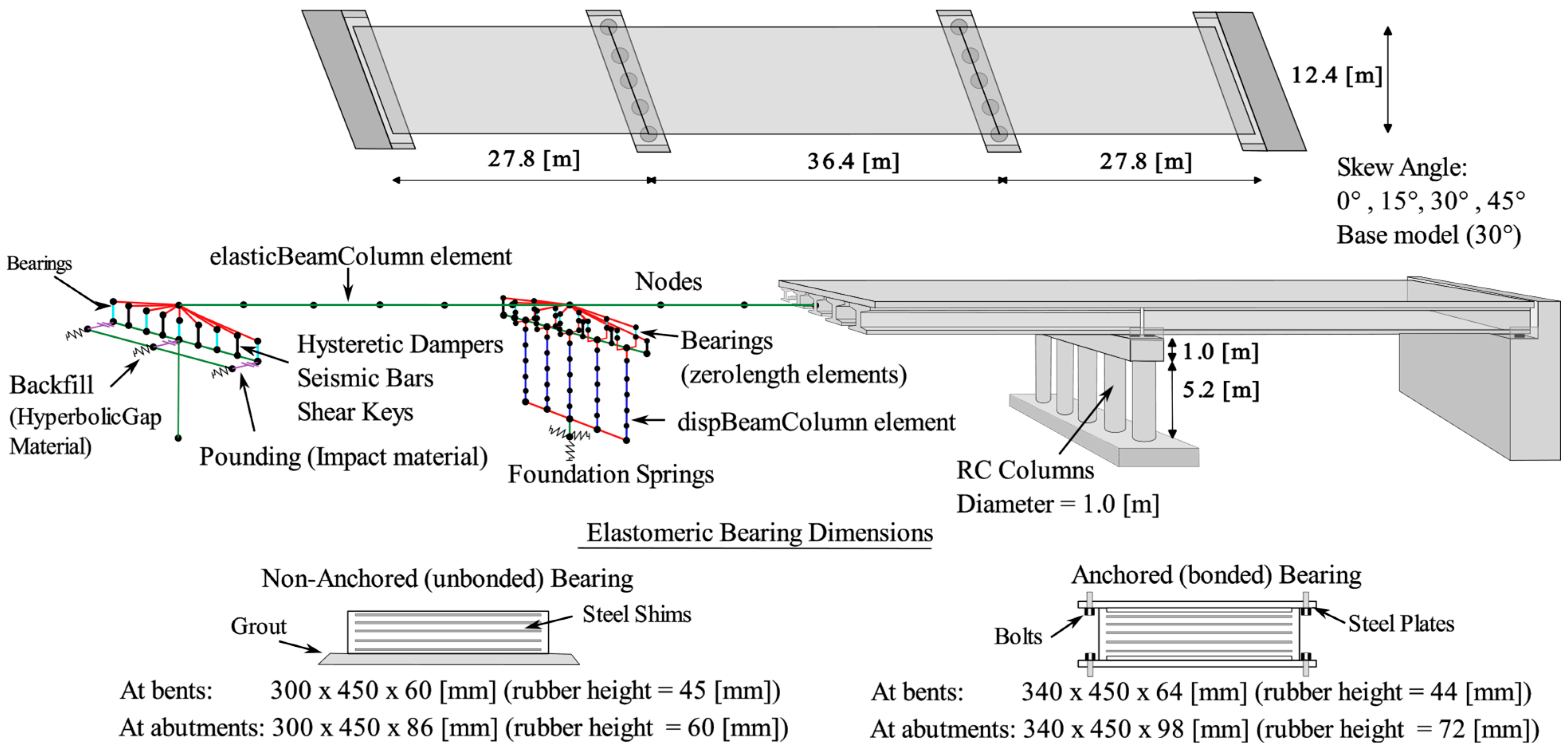
2. Prototype Bridge Description

The selected case study is a three-span skewed bridge that presents the typical configuration of a Chilean highway bridge, i.e., precast prestressed concrete girders supported on laminated elastomeric bearings, a continuous RC deck, multi-column bents, and seat-type abutments. The case study presents a skew angle of 30°, five girders per transverse section, five columns per bent, and spread footings, as shown in Figure 2.
The studied bridge is located in Northwest Santiago, the capital of Chile, and two site conditions are considered to compare the effectiveness of the hysteretic dampers at different site conditions. The first one corresponds to a site with a time-averaged shear-wave velocity in the first 30 m, Vs30, of 600 [m/s], with a predominant period of the site Tg lower than 0.2 [s], which corresponds to Site Class C (Soft Rock) according to ASCE 7–16 classification [34]. The second one corresponds to a site with a Vs30 of 270 [m/s], with a Tg between 0.2 and 0.4 [s], which corresponds to Site Class D (Stiff Soil) according to the ASCE 7-16 classification [34].
The prototype bridge superstructure is assumed to be supported on non-anchored (unbonded) and anchored (bonded) laminated elastomeric bearings [35] since recent studies have shown the influence of bonding bridge elastomeric bearings [15,35] and also represent the conditions of Chilean bridges before and after the 2010 Maule earthquake (i.e., pre- and post-2010). It is worth mentioning that these laminated elastomeric bearings are not designed as seismic isolators. Instead, they represent a cost-effective device implemented in small- to medium-span bridges to satisfy vertical and horizontal service-level actions, such as dead loads, temperature, concrete creep, and shrinkage, among others [35]. Additionally, the influence of RC shear keys and damper hysteretic behavior (i.e., recentering hysteretic dampers) was also analyzed, initially resulting in six different bridge conditions, as listed in Table 1. In later sections of this paper, comparisons with unidirectional dampers and different skew angles are also analyzed and discussed.

Modeling Details for the Case Studies

Three-dimensional nonlinear FE models were developed in OpenSees [32] to represent the different bridge conditions. An overview of the models is shown in Figure 2. The bridge superstructure was modeled using elasticBeamColumn elements since it is supposed to remain elastic during the expected loads [36]. Columns were modeled through five dispBeamColumn elements with fiber sections using Concrete02 and Steel02 materials [15]. Cap beams were modeled using elasticBeamColumn elements [15]. Foundations were represented through elastic translational and rotational springs following the recommendations of Gazetas [37]. Abutments were modeled using elasticBeamColumn elements to represent the abutment wall [15]. Pounding between the superstructure and abutments was modeled through a force-based approach by using springs at each abutment. This spring model consists of zero-length elements with the Impact material proposed by Muthukumar [38]. The Impact material, which is a bilinear approximation of the Hertz model, has been widely used in studying pounding in bridges since it can simulate the impact force and the resulting energy dissipation [39,40]. In this study, the impact material was implemented as a compression-only gap in OpenSees with an initial gap of 0.1 m. The parameters for such material were obtained using the expressions proposed by Muthukumar [38], resulting in a yield displacement of 0.16 cm, an initial stiffness (K1) equal to 850 MN/m, and a secondary stiffness (K2) equal to 292 MN/m. The passive soil resistance at the abutments was modeled with HyperbolicGap material following the recommendations of Caltrans [41] and Shamsabadi et al. [42]. Steel stoppers for the bridge in its pre-2010 condition were modeled using an elasticPPgap material in parallel with a Hysteretic material, following the recommendations from Rubilar [43]. Internal RC shear keys for the bridge in its post-2010 condition were modeled through elasticPPgap materials, according to Megally et al. [44]. External RC shear keys were modeled through an elasticPPgap material in parallel to a hysteretic material, according to Goel and Chopra [45]. Seismic bars were modeled through a Hysteretic material, following the recommendations of Martinez et al. [46] and Aldea et al. [15]. Non-anchored elastomeric bearings were modeled through FlatSliderBearing elements [15], following Steelman et al.’s [47] and Rubilar’s [43] recommendations. Anchored elastomeric bearings were modeled through ElastomericBearingBoucWen elements. According to the Chilean BDM [13], the shear modulus of laminated elastomeric bearings (G) for seismic analysis can be considered as 1.27 MPa. Then, the effective lateral stiffness of laminated elastomeric bearings can be calculated as K e f f = G A / h , where A is the area of the elastomeric bearing and h is the height of the elastomer. In Chile, elastomeric bearings for this type of bridge are typically made of neoprene rubber 60 Shore A. More detailed modeling features and parameter calibration based on experimental data are specified in studies by Aldea et al. [15], Birrell et al. [48], and Pinto et al. [49].
Hysteretic dampers with and without recentering capabilities were modeled using uncoupled zero-length elements acting in both horizontal directions located in the superstructure-substructure interface between the girders. For dampers without recentering, Steel02 material from the OpenSees [32] library was used following the recommendations from Bazaez and Dusicka [21,22]. Additionally, a MinMax material was used to limit the maximum displacement of the damper to 20 times the yield deformation since, at this deformation, the failure of the damper is expected to occur. On the other hand, hysteretic dampers with recentering capabilities were modeled using the SelfCentering material from the OpenSees [32] library. Parameters for the recentering damper were derived from the experimental results of Shreshta et al. [30].

3. Hysteretic Damper Design

The performance-based earthquake engineering (PBEE) framework [50,51] was used to design the hysteretic dampers and assess the performance of the bridges, as shown in Figure 3. It is important to note that the methodology used in this study is thought for critical or essential multi-span girder bridges supported on elastomeric bearings, whose failure due to span unseating may produce significant connectivity disruption and economic losses. Requirements of the NCHRP-949 [52] and CSA-S6 [53] for essential and major-route bridges, respectively, were taken as a baseline to define the performance objectives [54,55] to be used in the design of the hysteretic dampers. In this context, three performance levels (PLs), namely, fully operational, operational, and extensive damage, are proposed to be evaluated at different seismic hazard levels, quantified through ground-motion return periods, as shown in Table 2. Qualitatively, at the fully operational level (PL1), the bridge and its components must ensure full serviceability immediately after the earthquake. Thus, there should be minimal inelastic incursions and residual displacements. At the operational level (PL2), service must be ensured for emergency vehicles and damage should be repairable, expecting a minor inelastic response on bridge components. Finally, at the extensive damage level (PL3), permanent offsets are expected, as well as a large inelastic response of components; thus, major repairs must be carried out. On the other hand, ground-motion return periods were adapted from the same documents (i.e., [52,53]) for the Chilean subduction zone.
In this study, the hysteretic damper design is proposed to be verified based on the probability of exceeding a specific damage state (also called the probability of damage in this paper) at the respective PL. The proposed design verification is similar to that proposed by Pang et al. [56] and Bolvardi et al. [57] for wood-frame and cross-laminated timber buildings, respectively. However, the probability of damage is used instead of the non-exceedance (NE) probability, as suggested by [56,57]. Moreover, [56,57] used NE probabilities of 50% for typical code-based performance levels. In this context, the maximum allowable probability of damage considered in this study is 30% for both PL1 and PL2, while for PL3, the probability of damage is limited to 20% to prevent major losses. These PLs will be subsequently verified for each bridge condition (Table 1) using MSA [33], where each stripe represents the respective hazard level.
The engineering demand parameters (EDPs) used in the study are the elastomeric bearing shear strain and the relative displacement between the superstructure and substructure, as shown in Table 3, since various studies [15,36,58,59] have shown that in skewed multi-span girder bridges, the controlling parameters are related to the elastomeric bearing deformations and the seat-length used to prevent span unseating. On the other hand, hazard levels are defined through a probabilistic seismic hazard analysis (PSHA) [60,61], as explained in the following section.

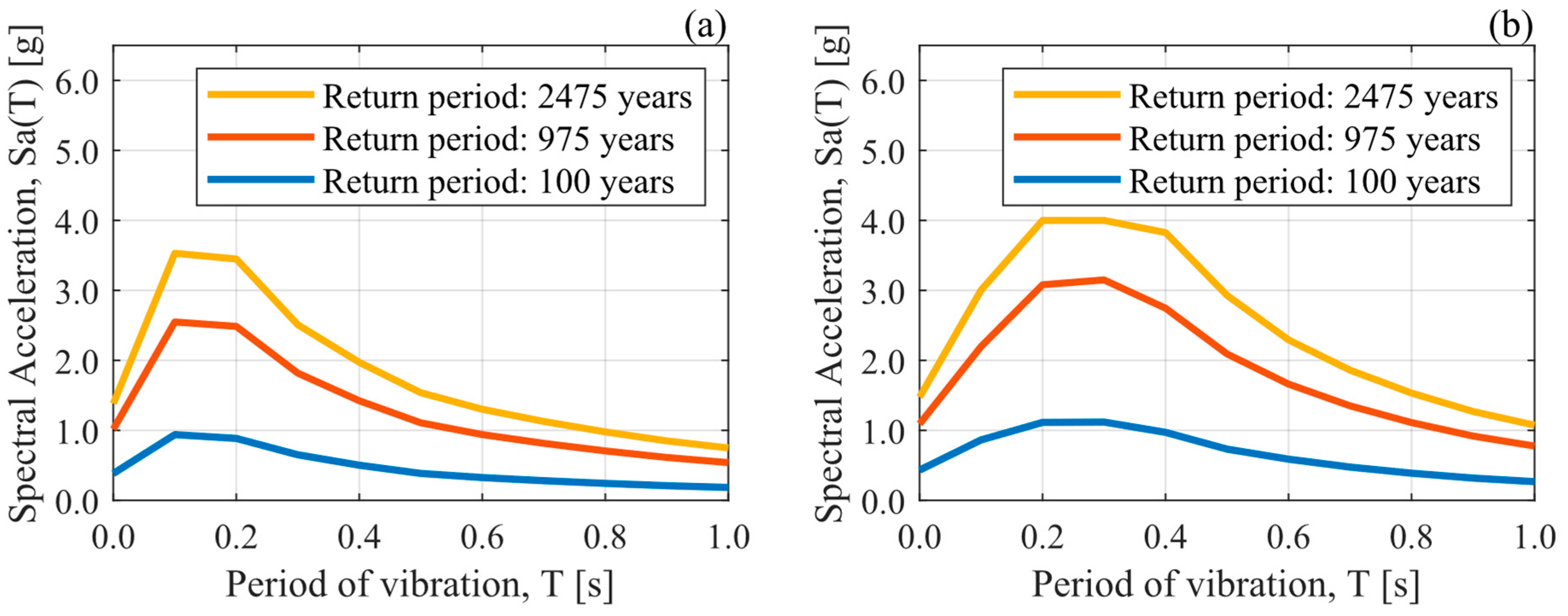
3.1. Probabilistic Seismic Hazard Analysis (PSHA)

A PSHA [60,61] was performed in the case study to design the dampers and select ground-motion acceleration records to verify the proposed performance levels through MSA [33]. The OpenQuake engine [63] was used to conduct the PSHA. The source model considers the subduction geometry from Hayes et al. [64], along with the zonification and recurrence model from Poulos et al. [65], together with the active-shallow-crust model from the SARA project [66]. Ground-motion models (GMMs) considered for subduction interface events are those proposed by Idini et al. [67] and Montalva et al. [68], combined through a logic tree [69] with equal weights. For subduction inslab earthquakes, only the GMM of Montalva et al. [68] is considered. Finally, for active-shallow-crust faults, the GMMs of Akkar et al. [70], Bindi et al. [71], and Boore et al. [72] are employed, combined through a logic tree [69] with equal weights. Figure 4 shows the uniform hazard spectra (UHS) for pseudo-acceleration spectral ordinates obtained from the PSHA. These UHS will be used for the damper design procedure in Section 3.2.
For the MSA, three stripes are considered for each site condition. The stripes are related to hazard levels of 100, 975, and 2475 return periods. The ground-motion intensity measure (IM) adopted is the 5%-damped pseudo-acceleration spectral ordinate 8 (Sa) at 0.8 [s] (fundamental period, Tn, of the pre-2010 and post-2010 bridge cases) since previous studies have stated that Sa(Tn, 5%) is a suitable IM for skewed highway bridges [73]. Values of Sa(0.8s, 5%) for each stripe are shown in Table 4. Furthermore, a deaggregation analysis was performed at each hazard level to find the mean magnitude and mean source-to-site distance to construct a conditional spectrum [74] for each stripe. The results of the deaggregation (not shown in this paper for brevity) at all the considered hazard levels showed that interface events contributed more than 92% to the hazard at the site. Thus, the Idini et al. [67] GMM for interface earthquakes was used to construct the conditional spectrum. From this, 30 records were selected for each stripe, matching them to the conditional spectrum using the methodology proposed by Baker et al. [75]. These acceleration records were obtained from the Chilean National Seismological Center (CSN) [76], the Chilean National Network of Accelerometers (RENADIC) of the University of Chile [77], and the Siber-Risk Strong Motion database [78]. To avoid an excessive bias in the seismic response of the bridges due to the amplitude scaling of the ground-motion records, the amplitude scaling factor was limited to 4 [79,80]. Moreover, based on the deaggregation results, only interface events were considered. It is worth mentioning that the selection procedure matches the geometric mean of the two orthogonal horizontal components of the records, as that is the intensity measure used in the GMM proposed by Idini et al. [67]. For the MSA, the vertical component of each record is also considered with the same amplitude scaling factor as both horizontal components. The effect of the ground motion incidence angle is not considered in this study, as Wang et al. [81] found that the incidence angle has only a minor influence on the response of skewed bridges, particularly when hysteretic dampers are used. The pseudo-acceleration response spectra of the selected records at each stripe are shown in Figure 5.
Figure 3. Performance-based design of hysteretic dampers. (The mentioned references are Xiang et al. 2019 [82]; Bazaez & Dusicka 2018 [22]).
Buildings 14 01778 g003
Figure 4. Uniform hazard spectra for return periods of 100, 975, and 2475 years obtained from PSHA for the case study. (a) Soft Rock (Vs30 = 600 [m/s] and Tg < 0.2 [s]). (b) Stiff Soil (Vs30 = 270 [m/s] and 0.2 [s] < Tg < 0.4 [s]).
Buildings 14 01778 g004
Figure 5. The 5%-damped pseudo-acceleration spectra for the geometric mean of horizontal components of the selected ground-motion records. (a) Soft Rock (Vs30 = 600 [m/s] and Tg < 0.2 [s]). (b) Stiff Soil (Vs30 = 270 [m/s] and 0.2 [s] < Tg < 0.4 [s]).
Buildings 14 01778 g005

3.2. Damper Design Variables

Hysteretic dampers are included at the superstructure-the substructure interface to fulfill the proposed performance criteria, replacing the internal RC shear keys commonly used in girder bridges. Elastomeric bearings are assumed to act in parallel with the dampers, and these are assumed to act in series with the RC bent (i.e., substructure). The design variables for the hysteretic damper are mainly its initial stiffness ( K d ) and yield force ( F y d ) . The fuse methodology proposed by Xiang et al. [82] and Bazaez and Dusicka [22] is used to estimate the initial values of the design variables. Then, the design needs to be iterated and verified to ensure compliance with the performance objectives stated in Table 2. For estimation of the initial design variables only, bilinear behavior was considered for the dampers and elastomeric bearings, and linear behavior was considered for the RC bents. The initial design procedure is applied separately at ground-motion hazard levels with return periods of 100 and 975 years using the corresponding uniform hazard spectrum obtained from PSHA [60,61], i.e., the design procedure for each hazard level is the same. The return period of 2475 years is not directly considered to estimate the initial stiffness and strength of the dampers, as the methodology aims at achieving operational performance (PL2). However, the 2475-year hazard level is considered for verifying the allowed probability of damage. It should be mentioned that the original procedure proposed by Xiang et al. [82] was developed for sliding rubber bearings (i.e., non-anchored or unbonded elastomeric bearings), and the one proposed by Bazaez and Dusicka [22] was developed for BRBs in multi-column bents. However, in the scope of this paper, the procedure was applied for anchored and non-anchored elastomeric bearings. In the case of recentering devices, the hysteretic curve maintains the initial stiffness and yield strength obtained through the design procedure, and the remaining parameters need to be adjusted to reflect the behavior of a particular damper, e.g., CuAlMn-shape memory alloy dampers [30,31].

3.3. Damper Design Results

For the case study in this paper, the target design displacement for both PL1 and PL2 was taken as the elastomeric bearing shear strain stated in Table 3. On the other hand, the damper design ductility was assumed to be 1.5 for PL1 to allow minor inelastic excursions in the damper and 5.0 for PL2 to achieve an adequate level of hysteretic damping [21,83]. The design results in both site conditions (Soft Rock and Stiff Soil) are shown in Table 5, for seismic hazard levels with return periods of 100 and 975 years. The most conservative design, considering the different seismic hazard levels, is used for each soil condition. The design for the Stiff Soil site condition is controlled by the results for a return period of 975 years, whereas for the Soft Rock site condition, it is controlled by the results obtained for a return period of 100 years. The force–displacement behavior of the dampers with and without recentering is shown in Figure 6 for the design in Soft Rock and Stiff Soil site conditions. Incorporating hysteretic dampers stiffened the overall system, resulting in fundamental periods of 0.51 s for Soft Rock and 0.32 s for Stiff Soil. The design dampers provide additional hysteretic damping of 30% for the non-recentering dampers and 6% for the recentering dampers.
As shown in Figure 6 and Table 5, the yield strength and the initial stiffness of the dampers obtained for Stiff Soil are approximately six times higher than those for Soft Rock. This result poses a physical constraint in the implementation of hysteretic dampers, as a very large damper may be needed to reach these properties. Although the physical implementation of the dampers is out of the scope of the present paper, it presents an important constraint to be considered in real applications. It is also possible that, with these high levels of force and stiffness, the forces transferred to the columns may cause them to experience large inelastic excursions. Therefore, the demands transferred to the substructure are ulteriorly verified in Section 4.2.

3.4. Design Verification

To obtain the probabilities of damage for design verification, damage states (DSs) must agree with the performance levels (PLs) and the EDPs specified in Table 3. DSs are assumed to follow a lognormal distribution, with medians and logarithmic standard deviations (i.e., dispersion) summarized in Table 6. Dispersion values recommended by Nielson [84] were considered. The maximum value between transverse and longitudinal directions was chosen for each EDP.

Multiple Stripe Analysis and Probability of Damage

MSAs were performed to obtain the probabilities of damage for the case study in the different bridge conditions mentioned in Section 2. For the analysis, 30 records were used at each of the 3 stripes. Each record consists of two horizontal ground motions applied in the longitudinal and transverse direction of the bridge and their corresponding vertical component. Then, by using Equation (1), P E D P i [ D S j | I M ] is obtained, which corresponds to the probability of exceeding a particular D S j (related to a specific E D P ), conditioned on an IM value. This is achieved by integrating the multiplication of the probability of exceeding a particular D S j conditioned on a E D P value, P D S j d s E D P = e d p , with the probability density function of the E D P conditioned on an IM value, f E D P e d p I M = i m . As a given D S j can be characterized by multiple EDPs (see Table 6), the system probability of exceeding a particular D S j conditioned on an IM value is estimated through Equation (2) [62]. The upper bound of Equation (2) is considered to conservatively estimate the probability of the system exceeding a particular D S j conditioned on an IM value.
P E D P i [ D S j | I M ] = P D S j d s E D P i = e d p f E D P i e d p I M = i m   d ( e d p )
max P E D P i D S j I M < P s y s t e m D S j I M < 1 E D P i ( 1 P E D P i D S j I M )
P s y s t e m D S j I M P E m a x
where P E m a x is the maximum allowable probability of damage proposed in Table 2. Then, the performance objectives were evaluated through discrete probabilities following Equation (3) for the six bridge conditions shown in Table 1. Figure 7 presents the probability of exceeding the corresponding PL at different seismic hazard levels. Figure 7a shows the performance results for Soft Rock site conditions, while Figure 7b shows the results for Stiff Soil site conditions. Both figures show that the performance levels for the bridges with dampers are successfully verified with a maximum 30% exceedance probability for PL1 and PL2, and with a maximum 20% exceedance probability for PL3, except for the RA condition at the Soft Rock site.
The pre-2010 bridge condition shows more than 70% exceedance probability for the proposed performance levels and for both site conditions, apart from PL1 for Soft Rock site conditions with a 50% exceedance probability. Similarly, the post-2010 condition has 50% and 35% probabilities of exceeding PL2 and PL3, respectively, for Soft Rock, and 45%, 76%, and 75% probabilities of exceeding PL1, PL2, and PL3, respectively, for Stiff Soil site conditions. For bridges with anchored laminated elastomeric bearings (i.e., post-2010, HA, RA), it is observed that for all cases, the HA condition experiences a lower probability of damage. On the other hand, for the case studies without anchored elastomeric bearings (i.e., pre-2010, HNA, RNA), in most cases, the HNA condition has the lowest probability of damage. These results are due to the larger energy-dissipation capacity of the HA and the HNA cases compared to the pre-2010, post-2010, and recentering cases.
The fragility curves depicted in Figure 8 clearly illustrate the outcomes across all damage states (performance levels) for the soft rock site condition, showing that incorporating bidirectional hysteretic dampers significantly reduces the probability of damage compared to the pre- and post-2010 bridge cases.

4. Effect of Hysteretic Dampers on Seismic Performance

4.1. Influence of Dampers’ Direction

In previous sections, hysteretic dampers were considered to act on both principal directions of the bridge (i.e., longitudinal and transverse). On the contrary, this section assesses the performance of unidirectional dampers acting only in the transverse direction since this direction has been commonly proposed in various research on highway bridges [17,85].
Figure 9 shows the probability of exceeding a performance level for different hazard levels when using only transverse metallic dampers. The results demonstrate that even though unidirectional dampers can reduce the probability of bridges exceeding a specific PL compared to bridges without dampers (pre-2010 and post-2010), the reduction is not enough to ensure the performance criteria in terms of maximum damage probabilities. This occurs because unidirectional dampers cannot restrain longitudinal displacements, which, in many cases, may be greater than transverse displacements. This result highlights the importance of considering both directions when designing and assessing skewed bridges with hysteretic dampers.

4.2. Influence of Dampers on the Substructure Response

The impact of bidirectional dampers on the seismic response of the substructure was analyzed to evaluate their effectiveness as a protective measure in accordance with capacity design principles. This is crucial because prior studies [22,23] have demonstrated that integrating metallic hysteretic dampers can increase the seismic demands on other structural components, such as columns and foundations.
In this context, the probabilities of column damage are computed using the displacement ductility of columns as EDP and a single damage state following a lognormal distribution with a median of 1.0 and a dispersion of 0.25, representing yielding of these elements. The ductility from longitudinal (x) and transverse (y) directions are conservatively combined according to Equation (4).
μ = μ x 2 + μ y 2
Figure 10 presents the fragility curves using a least-square regression and considering the displacement ductility of columns as EDP. In Figure 10a, it can be observed that for Soft Rock site conditions, the HA configuration has a lower column damage probability than the analogous configuration but with internal RC shear keys (i.e., post-2010). This reflects the high energy-dissipation capacity of the hysteretic dampers, which can reduce the demands of the superstructure without significantly increasing the forces transferred to the substructure. In the RA condition, the column damage probability is similar to the one for the bridge with shear keys (i.e., post-2010). In contrast, for non-anchored bridge conditions (i.e., pre-2010, HNA, and RNA), column damage probabilities are negligible, demonstrating that, the columns are unlikely to reach yielding for these bridge configurations and Soft Rock site conditions. Figure 10b shows that bridges with dampers have much higher column damage probabilities for Stiff Soil site conditions than those for Soft Rock site conditions. This result implies that dampers designed for Stiff Soil site conditions transfer larger demands to the substructure, and thus yielding of the columns is more likely to occur.
These results indicate that while dampers can reduce the demands on the substructure in some cases, they can increase them in others. Therefore, the substructure’s capacity must be verified at the end of the damper design process to ensure adequate performance.

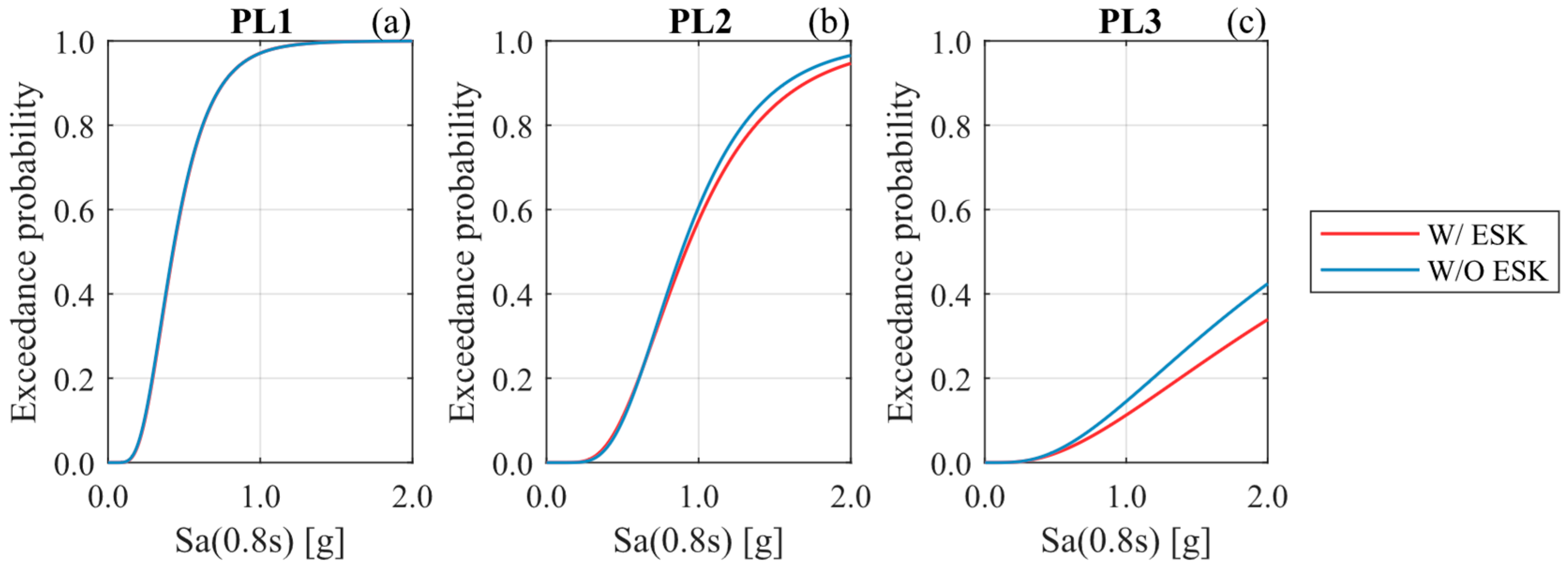
4.3. Influence of Including External Shear Keys with Hysteretic Dampers

The hysteretic dampers proposed in this study replace the internal shear keys but not the external ones. Thus, the influence of external shear keys (ESKs) in bents and abutments is analyzed to determine if the ESKs are still necessary when energy-dissipation devices are incorporated. The analysis considers ESKs and hysteretic dampers with non-anchored (unbonded) elastomeric bearings (i.e., HNA bridge) on Soft Rock site conditions. Figure 11 reveals that the bridge without external shear keys (W/O ESK) exhibits slightly higher fragility than the one with external shear keys (W/ESK). Moreover, the differences are primarily observable in Performance Levels 2 and 3, as the fundamental role of common shear keys is to prevent excessive lateral displacements. This also suggests that the presence of external shear keys does not enhance operational performance when used in combination with other hysteretic dampers. Nevertheless, including external shear keys is considered a sound engineering practice to mitigate the risk of span unseating, particularly in scenarios where dampers might fail prematurely.

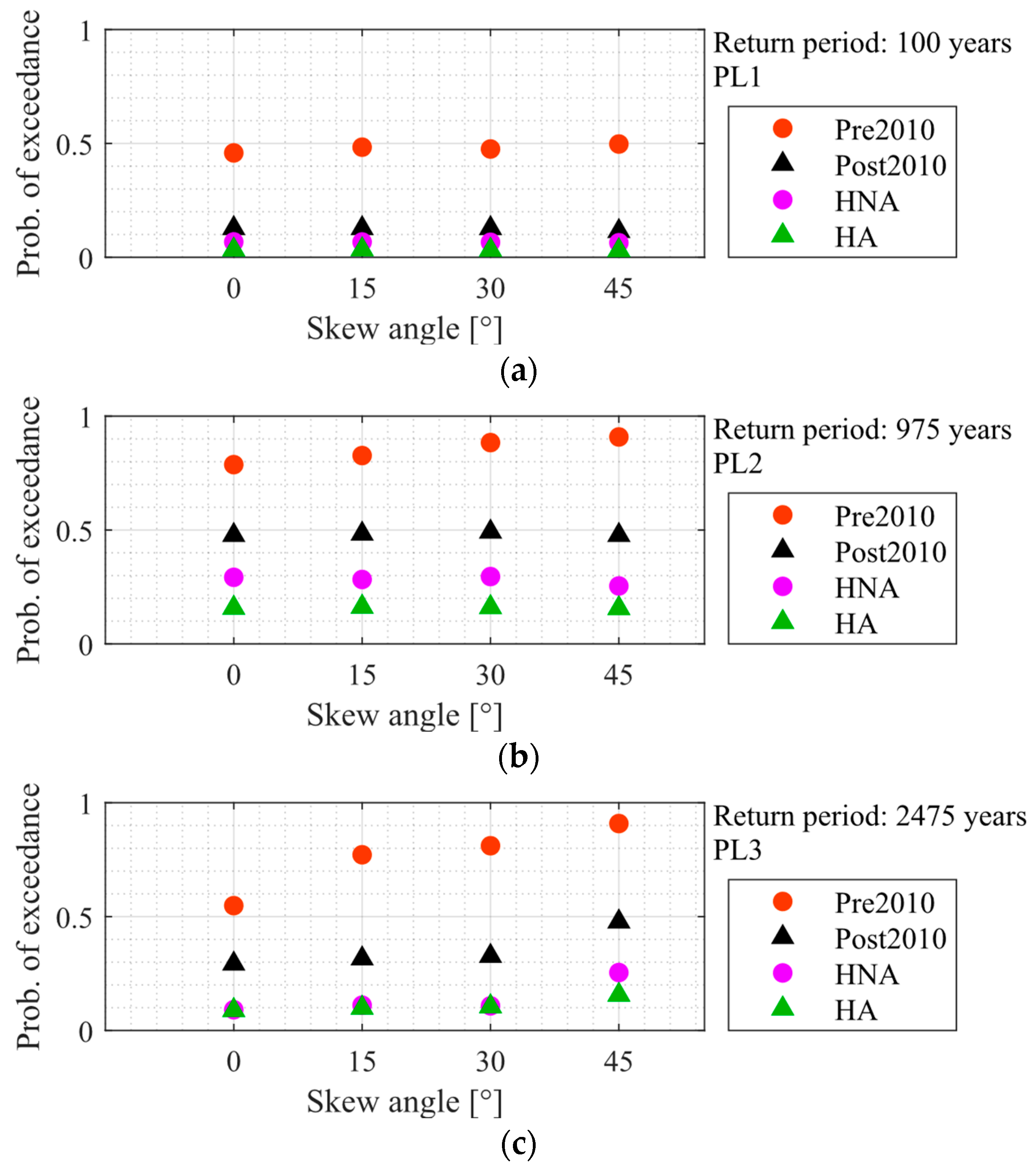
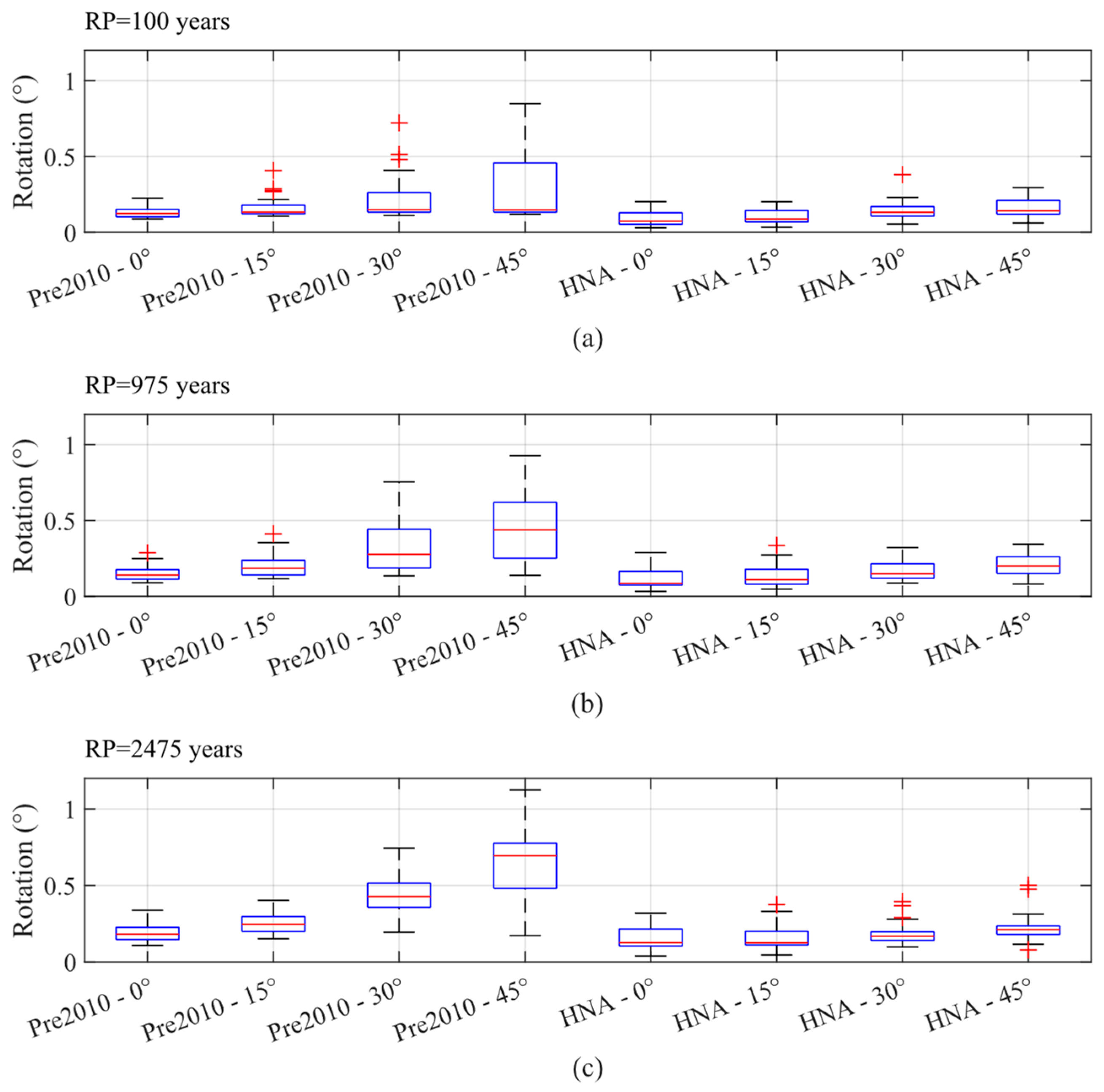
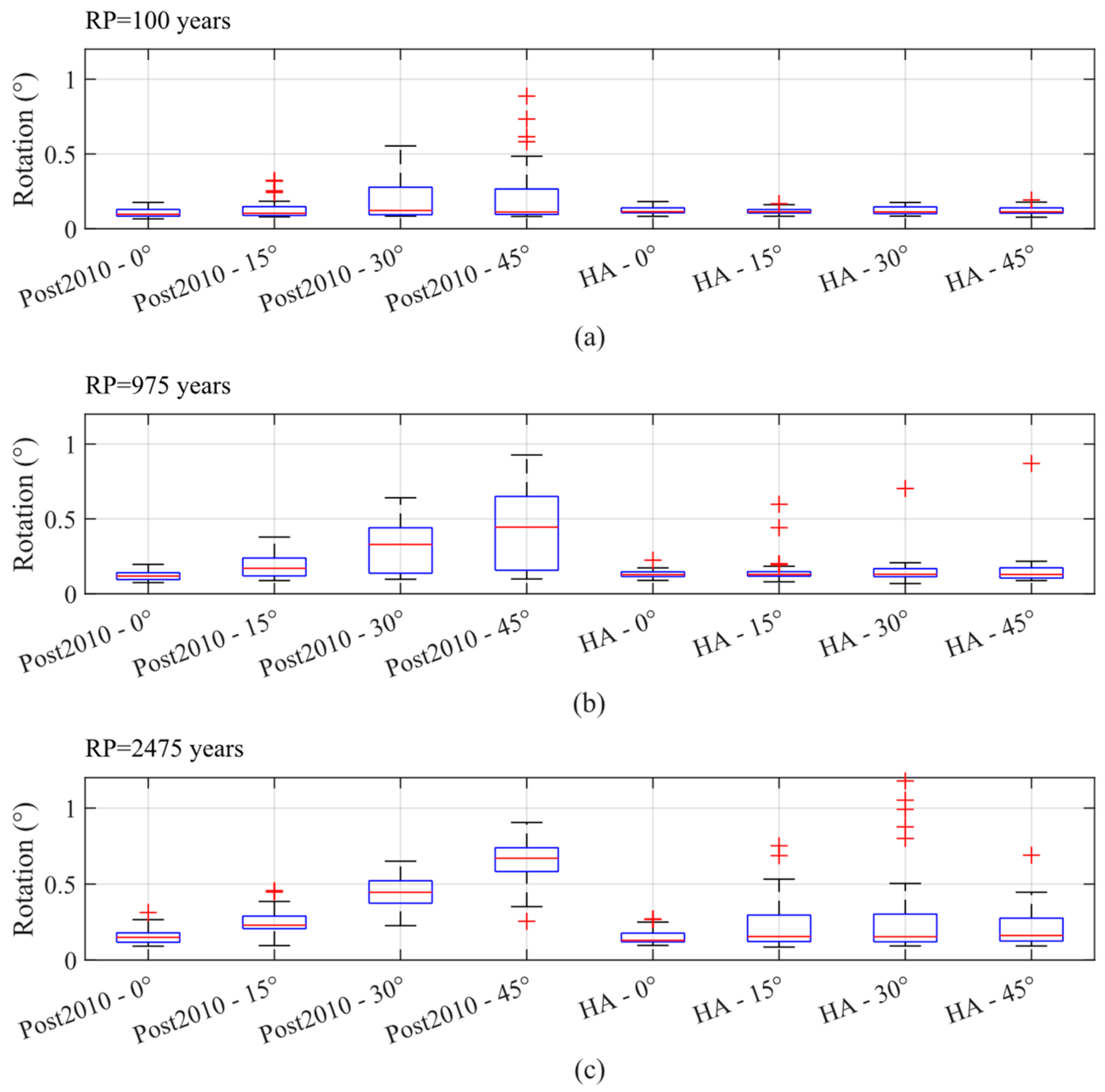
4.4. Influence of Skew Angle

To study the influence of the skew angle on the seismic performance of highway bridges with energy-dissipation devices, skew angles of 0°, 15°, 30°, and 45° were considered. In this context, probabilities of damage were obtained considering the pre-2010, post-2010, HNA, and HA bridge conditions and Soft Rock site conditions. The probabilities of exceedance of PL1, PL2, and PL3 are shown in Figure 12. These results show that in all cases, for all the performance levels considered, straight bridges (i.e., the skew angle of 0°) are the least vulnerable ones, and there is an increased probability of damage as the skew angle increases for typical skewed multi-span bridge configurations (i.e., the pre-2010 bridge). These results are consistent with past research findings [10,11,15,36,58,59,86,87,88]. Notably, Figure 12 also demonstrates that the impact of the skew angle on the seismic performance of bridges equipped with passive hysteretic dampers is minimal. This finding is significant as it suggests that using hysteretic dampers may decouple skew angle considerations from bridge fragility assessments.
Skewed bridges are widely recognized for their seismic vulnerability, primarily due to the in-plane rotation of the superstructure, which can lead to span unseating [58]. To support this observation, Figure 13 shows the rotational response of the superstructure for different return periods and skew angles in the pre-2010 and HNA cases, while Figure 14 presents the same for the post-2010 and HA cases. Notably, these figures demonstrate a clear trend: in both pre-2010 and post-2010 scenarios, an increase in the skew angle corresponds to higher median and maximum rotational demands on the superstructure. However, a noteworthy contrast arises when examining bridges equipped with hysteretic dampers (i.e., HNA and HA). Remarkably, these bridges exhibit consistent median and maximum rotational demands, regardless of the skew angle. This observation further highlights the effectiveness of hysteretic dampers in mitigating the adverse effects of skew-induced rotational demands on bridge structures.

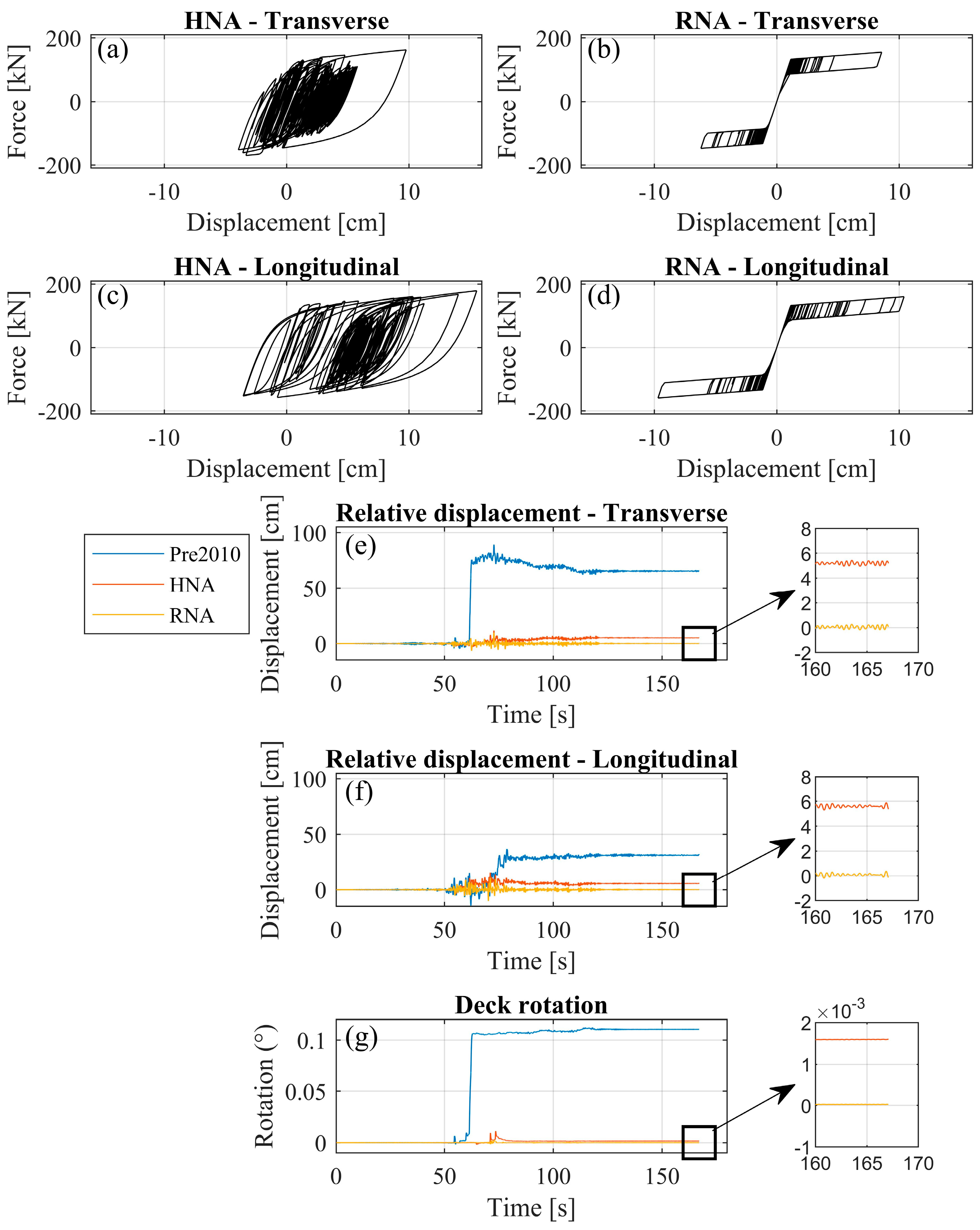
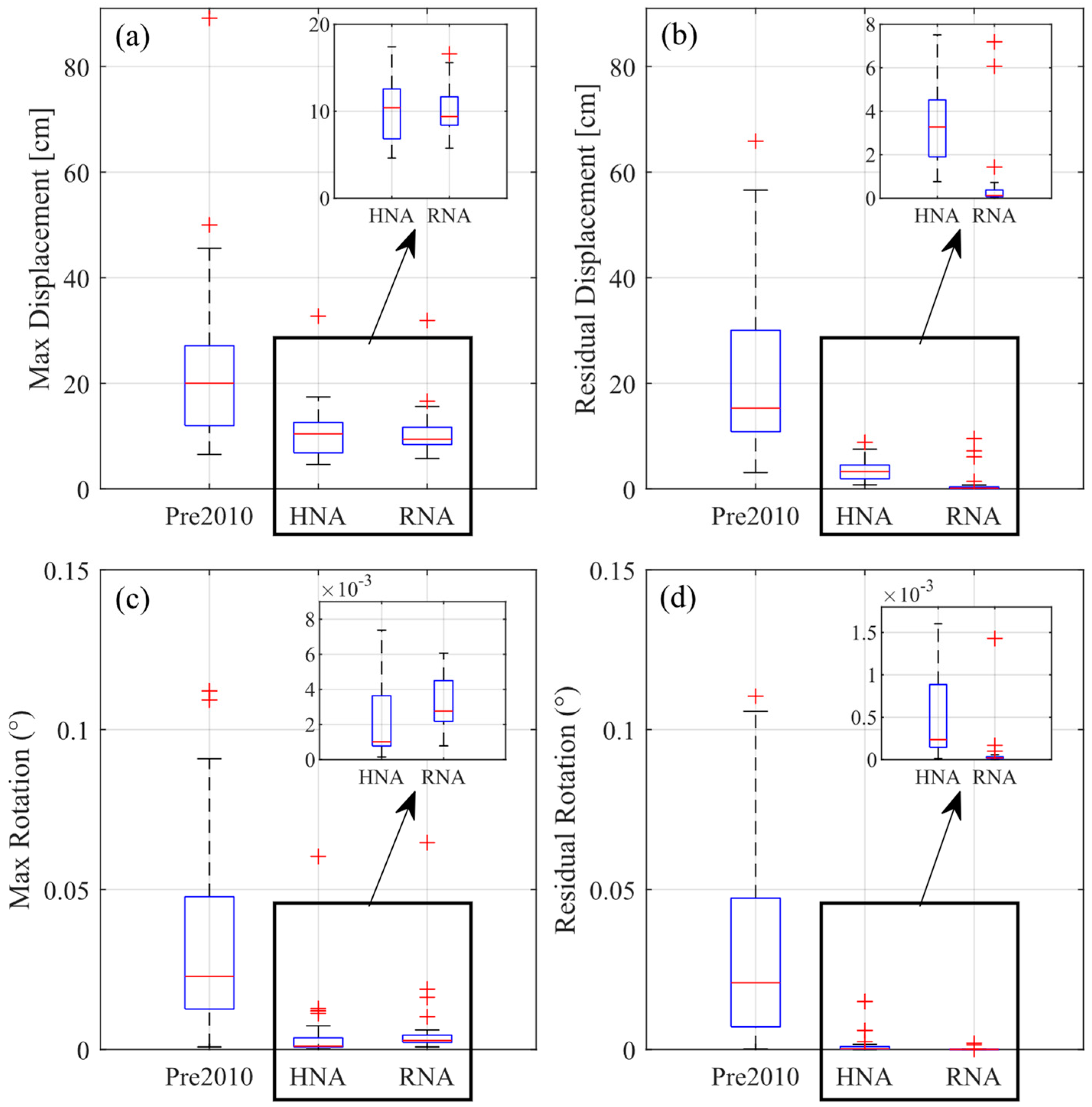
4.5. Influence of Recentering Dampers

Seismic responses using different hysteresis dampers with and without recentering capabilities are assessed in this section. With this aim, bridges with non-anchored elastomeric bearings (i.e., pre-2010, HNA, and RNA bridge cases) and Soft Rock site conditions were considered. Figure 15 illustrates the response of hysteretic dampers and the relative displacements and rotations between the superstructure and substructure for a ground motion corresponding to a seismic hazard level of 2475 years. In particular, the ground motion used was recorded in the station MAUL03R during the 2010 Mw8.8 Maule earthquake in Chile [78]. The results are presented in both the transverse and longitudinal directions, as well as time-history responses for relative displacement and superstructure rotation. The figure shows that hysteretic dampers used in the HNA (i.e., a hysteretic damper without recentering capability) case exhibit significant energy dissipation, as indicated by the wide hysteresis loops. This behavior is observed in both the transverse and longitudinal directions, suggesting effective performance in mitigating seismic forces. The hysteretic dampers used in the RNA case (i.e., hysteretic damper with recentering capability) show narrower hysteresis loops compared to the HNA case. This indicates less energy dissipation and suggests that RNA dampers may be less effective in seismic energy absorption than HNA dampers. Regarding relative displacement, the HNA and RNA cases result in significantly lower displacements compared to the pre-2010 design, indicating improved performance in reducing relative displacements. The time history of deck rotation reveals minimal rotation for both HNA and RNA cases compared to the pre-2010 design. This indicates that both damper types (i.e., with and without recentering capability) effectively control in-plane deck rotations, with the RNA case showing marginally better performance in residual displacements and rotations. The improved performance of these dampers over older designs (pre-2010) highlights their efficacy in seismic damage mitigation.
To better analyze the differences between both types of dampers (i.e., with and without recentering), Figure 16 presents box-plot comparisons of the relative superstructure-to-substructure response metrics for all ground motions with a return period of 2475 years. The metrics evaluated include the maximum relative displacement, residual displacement, maximum rotation, and residual rotation. Comparisons are made between pre-2010 designs, HNA, and RNA cases.
As previously stated, the pre-2010 design shows significantly higher responses compared to both HNA and RNA. The median maximum displacement for the pre-2010 design is 20 cm, while both HNA and RNA cases exhibit much lower maximum displacements, with a similar median response of around 10 cm. This represents an approximate 50% reduction in maximum displacement.
Similarly, HNA and RNA cases effectively reduce maximum rotations, with their median performances being quite similar. A slightly higher median response is observed in the RNA case, which may be attributed to a lower energy dissipation capacity.
Regarding the residual response, both HNA and RNA dampers significantly reduce the median residual displacements and rotations compared to the pre-2010 design. The median residual responses are reduced by about 90%. The RNA case shows a slightly better performance than HNA in minimizing the residual response, which is attributed to their recentering capabilities.
These results indicate that both types of dampers are highly effective in reducing peak relative displacements and rotations compared to older designs. The superior performance of RNA dampers in reducing residual responses is particularly important for achieving fully operational performance levels, where stringent residual displacement limits are imposed, making recentering dampers preferable.

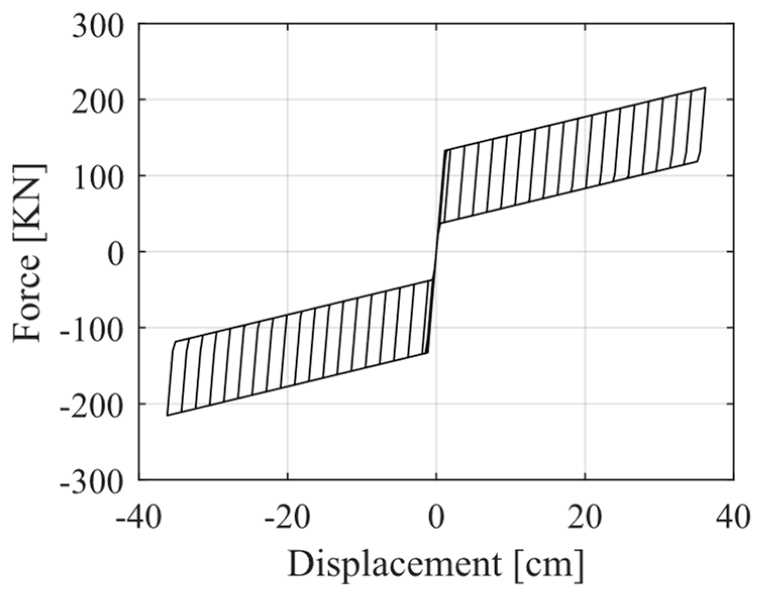
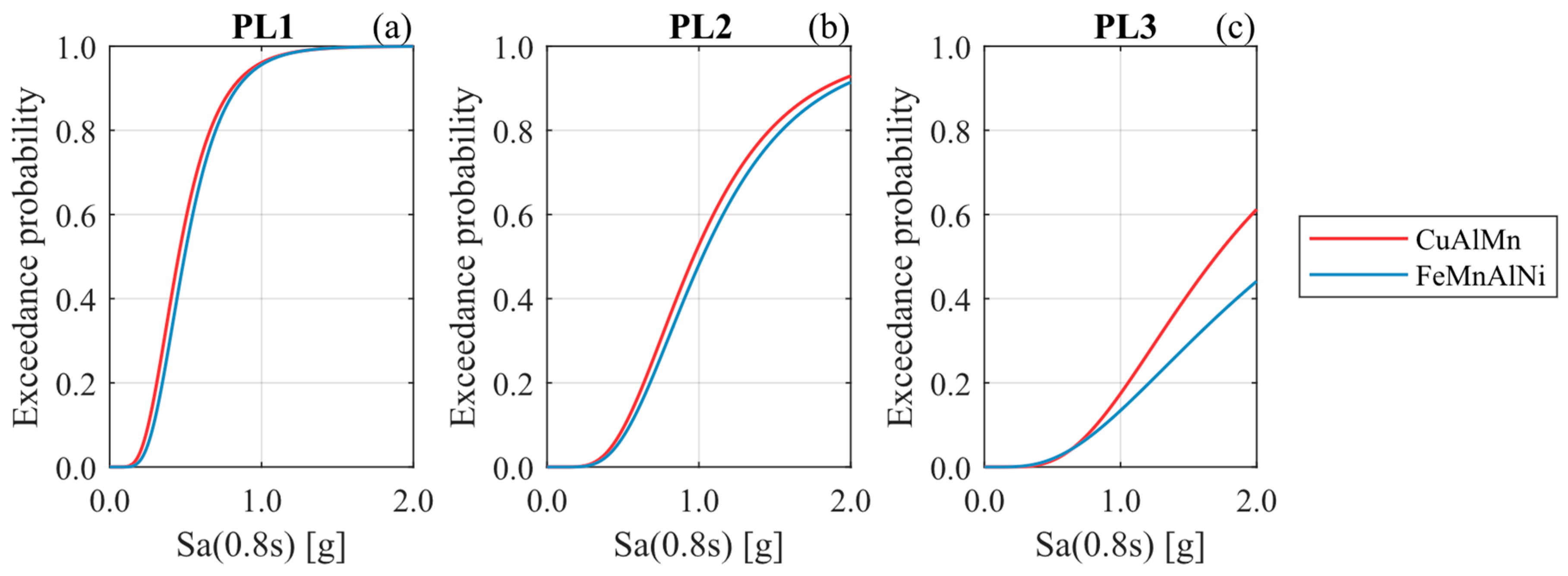
4.6. Influence of the Hysteretic Curve of Recentering Dampers

To analyze how the seismic performance varies using different hysteresis curves for the energy-dissipation devices with recentering capabilities, the bridge with non-anchored elastomeric bearings (i.e., RNA bridge) and Soft Rock site conditions were considered. For this, a FeMnAlNi [29]-shaped memory alloy was used in the design of the damper instead of the CuAlMn alloy [30]. This new damper follows a hysteretic curve according to Figure 17. Comparing this hysteretic curve with the one shown in Figure 6b, the FeMnAlNi SMA results in higher energy dissipation per cycle. Fragility curves (Figure 18) show that the change in the materiality slightly affects the seismic performance at PL1 and PL2. Differences are mainly observed at PL3 since higher hysteretic energy dissipation is expected at this performance level. Thus, the bridge with the FeMnAlNi SMA damper is less vulnerable because it allows more energy dissipation than the CuAlMn SMA damper. However, it should be noted that this result may not be generalized just based on the case study.

5. Summary and Conclusions

In this study, a performance-based methodology is used for designing hysteretic dampers implemented in skewed highway bridges. The seismic performance of different bridge configurations with anchored and non-anchored elastomeric bearings, considering hysteretic dampers with and without recentering capabilities, was analyzed. Based on the results, the following conclusions are drawn:
  • Bidirectional hysteretic dampers with and without recentering capabilities are an effective measure to improve the seismic performance of skewed multi-span highway bridges compared to Chilean bridges built prior to 2010 (i.e., pre-2010) and repaired after the 2010 Maule earthquake (i.e., post-2010). In this context, bidirectional dampers were able to reduce the probability of damage by at least 20% compared to the pre-2010 and post-2010 cases. The improvement in seismic performance was even noticeable at lower levels of ground-motion intensity (PL1), something that traditional seismic bars and reinforced concrete shear keys in the post-2010 case failed to achieve since shear keys only activate at high transverse displacements.
  • This study provides new evidence that unidirectional hysteretic dampers, which are placed only in the transverse direction, as suggested by other researchers [17], are insufficient for achieving desired performance levels. The probability of damage increased by at least a factor of 2.0 when unidirectional dampers were considered instead of bidirectional dampers. This finding underscores the necessity for bidirectional dampers, which are essential for achieving operational performance levels in skewed bridges.
  • From a capacity design perspective, the results showed that hysteretic dampers can effectively reduce the seismic demands transmitted to the substructure in certain cases while they can increase them in others. Hence, it is essential to conduct capacity design checks on the substructure to avoid excessive demand and potential damage. The damper design parameters need to be adjusted in cases where large forces are transferred to the bents and foundations. This step ensures that the benefits of dampers do not lead to unintended structural issues. Moreover, this study suggests that including external RC shear keys, despite their slight impact on seismic performance when used with dampers, is crucial to prevent span unseating in the case of damper failure.
  • For bridges without dampers, this study confirms that rotational demands and damage probability significantly increase with the skew angle, especially for PL3. Conversely, it is worth highlighting that the skew angle has a minimal influence on the rotational response and seismic fragility of bridges equipped with bidirectional hysteretic dampers and anchored elastomeric bearings. This negligible effect of the skew angle on damage probability is a significant finding, as using hysteretic dampers might allow for isolating the skew angle from bridge fragility considerations. This observation presents an additional advantage of employing bidirectional energy-dissipation devices in skewed bridges.
  • Bidirectional hysteretic dampers, particularly those with recentering capabilities, are recommended for improving seismic performance. They effectively reduce both displacements and rotations, minimizing the probability of damage. Dampers should be installed in both transverse and longitudinal directions to ensure comprehensive seismic performance improvements. The superior performance of recentering dampers in reducing residual responses is particularly important for achieving fully operational performance levels, where stringent residual displacement limits may be imposed, making recentering dampers preferable.
  • Recentering dampers with different materials or hysteretic curves slightly affect the fragility at PL2 and PL3 since there is no significant increase in energy dissipation. Further analysis and experimental research must be conducted regarding residual displacements and the practical application of this type of device.
  • This study provides valuable insights that can be directly used in engineering applications, particularly in the design and retrofitting of skewed highway bridges to enhance their seismic performance. While the performance-based design methodology used in this study can be implemented globally, the specific performance objectives are tailored for the case of Chile. For different regions, performance objectives can be referenced from various standards, such as NCHRP-949 [52] and the new AASHTO Guidelines for Performance-Based Seismic Design of Highway Bridges [89] for the United States and CSA-S6 [53] for Canada.
  • A large amount of experimental and numerical research is still warranted to attain more reliable damage states of various bridge components such as shear keys, laminated elastomeric bearings, RC columns, abutments, and bidirectional hysteretic dampers. Furthermore, conducting a sensitivity analysis on the mechanical properties of the dampers would be highly beneficial for understanding the robustness and extent of the findings presented in this study.

Author Contributions

Conceptualization, S.A. and R.B.; methodology, S.A., R.B., P.H., and R.A.; software, S.A.; validation, S.A., R.B., P.H., and R.A.; formal analysis, S.A., R.B.; investigation, S.A., R.B., P.H., and R.A.; resources, R.B. and P.H.; data curation, S.A.; writing—original draft preparation, S.A. and R.B.; writing—review and editing, S.A., R.B., P.H., and R.A.; visualization, S.A. and R.B.; supervision, R.B.; project administration, R.B.; funding acquisition, R.B. All authors have read and agreed to the published version of the manuscript.

Funding

This study was funded by the Chilean National Agency for Research and Development (ANID). Ramiro Bazaez gratefully acknowledges the support provided by ANID/FONDECYT/Regular grant N°1231941, and Pablo Heresi acknowledges the support provided by ANID/FONDECYT/Initiation N°11230463.

Data Availability Statement

The data that support the findings of this study are available from the corresponding author upon reasonable request.

Acknowledgments

The authors would like to thank the Chilean National Seismological Center (CSN) and the National Network of Accelerometers of the Department of Civil Engineering of the University of Chile (RENADIC) for the installation and maintenance of strong-motion seismic stations, as well as for making their data publicly available.

Conflicts of Interest

The authors declare no conflicts of interest.

References

  1. Jennings, P. Engineering Features of the San Fernando Earthquake of February 9, 1971; Report 71-02; Earthquake Engineering Research Laboratory: Pasadena, CA, USA, 1971. [Google Scholar]
  2. Wakefield, R.R.; Nazmy, A.S.; Billington, D.P. Analysis of seismic failure in skew RC bridge. J. Struct. Eng. 1991, 117, 972–986. [Google Scholar] [CrossRef]
  3. Mitchell, D.; Bruneau, M.; Williams, M.; Anderson, D.; Saatcioglu, M.; Sexsmith, R. Performance of bridges in the 1994 Northridge earthquake. Can. J. Civ. Eng. 1995, 22, 415–427. [Google Scholar] [CrossRef]
  4. Han, Q.; Du, X.; Liu, J.; Li, Z.; Li, L.; Zhao, J. Seismic damage of highway bridges during the 2008 Wenchuan earthquake. Earthq. Eng. Eng. Vib. 2009, 8, 263–273. [Google Scholar] [CrossRef]
  5. Kawashima, K.; Takahashi, Y.; Ge, H.; Wu, Z.; Zhang, J. Reconnaissance report on damage of bridges in 2008 Wenchuan, China, earthquake. J. Earthq. Eng. 2009, 13, 965–996. [Google Scholar] [CrossRef]
  6. Buckle, I.; Hube, M.; Chen, G.; Yen, W.; Arias, J. Structural performance of bridges in the offshore Maule earthquake of 27 February 2010. Earthq. Spectra 2012, 28 (Suppl. S1), 533–552. [Google Scholar] [CrossRef]
  7. Kawashima, K.; Unjoh, S.; Hoshikuma, J.; Kosa, K. Damage of bridges due to the 2010 Maule, Chile, earthquake. J. Earthq. Eng. 2011, 15, 1036–1068. [Google Scholar] [CrossRef]
  8. Wilches, J.; Santa Maria, H.; Leon, R.; Riddell, R.; Hube, M.; Arrate, C. Evolution of seismic design codes of highway bridges in Chile. Earthq. Spectra 2021, 37, 2174–2204. [Google Scholar] [CrossRef]
  9. Dimitrakopoulos, E.G. Seismic response analysis of skew bridges with pounding deck-abutment joints. Eng. Struct. 2011, 33, 813–826. [Google Scholar] [CrossRef]
  10. Deepu, S.P.; Prajapat, K.; Ray-Chaudhuri, S. Seismic vulnerability of skew bridges under bi-directional ground motions. Eng. Struct. 2014, 71, 150–160. [Google Scholar] [CrossRef]
  11. Kun, C.; Jiang, L.; Chouw, N. Influence of pounding and skew angle on seismic response of bridges. Eng. Struct. 2017, 148, 890–906. [Google Scholar] [CrossRef]
  12. Wu, S.; Buckle, I.G.; Itani, A.M.; Istrati, D. Experimental Studies on Seismic Response of Skew Bridges with Seat-Type Abutments. I: Shake Table Experiments. J. Bridge Eng. 2019, 24, 04019097. [Google Scholar] [CrossRef]
  13. Ministerio de Obras Públicas (MOP). Manual de Carreteras, Volumen 3; MOP: Santiago, Chile, 2020; Available online: https://mc.mop.gob.cl/ (accessed on 22 October 2020).
  14. Wilches, J.; Santa María, H.; Riddell, R.; Arrate, C. Effects of changes in seismic design criteria in the transverse and vertical response of Chilean highway bridges. Eng. Struct. 2019, 191, 370–385. [Google Scholar] [CrossRef]
  15. Aldea, S.; Bazaez, R.; Astroza, R.; Hernandez, F. Seismic fragility assessment of Chilean skewed highway bridges. Eng. Struct. 2021, 249, 113300. [Google Scholar] [CrossRef]
  16. American Association of State Highway and Transportation Officials (AASHTO). AASHTO: Standard Specification for Highway Bridges, 16th ed.; AASHTO: Washington, DC, USA, 1996. [Google Scholar]
  17. Xiang, N.; Li, J. Seismic Performance of Highway Bridges with Different Transverse Unseating-Prevention Devices. J. Bridge Eng. 2016, 21, 04016045. [Google Scholar] [CrossRef]
  18. Xiang, N.; Alam, M.S. Comparative Seismic Fragility Assessment of an Existing Isolated Continuous Bridge Retrofitted with Different Energy Dissipation Devices. J. Bridge Eng. 2019, 24, 04019070. [Google Scholar] [CrossRef]
  19. Xiang, N.; Alam, M.S.; Li, J. Shake table studies of a highway bridge model by allowing the sliding of laminated-rubber bearings with and without restraining devices. Eng. Struct. 2018, 171, 583–601. [Google Scholar] [CrossRef]
  20. El-Bahey, S.; Bruneau, M. Buckling restrained braces as structural fuses for the seismic retrofit of reinforced concrete bridge bents. Eng. Struct. 2011, 33, 1052–1061. [Google Scholar] [CrossRef]
  21. Bazaez, R.; Dusicka, P. Repair of seismically damaged RC bridge bent with ductile steel bracing. Steel Compos. Struct. 2018, 26, 745–757. [Google Scholar] [CrossRef]
  22. Bazaez, R.; Dusicka, P. Performance assessment of multi-column RC bridge bents seismically retrofitted with buckling-restrained braces. Bull. Earthq. Eng. 2018, 16, 2135–2160. [Google Scholar] [CrossRef]
  23. Bazaez, R.; Dusicka, P. Cyclic behavior of reinforced concrete bridge bent retrofitted with buckling restrained braces. Eng. Struct. 2016, 119, 34–48. [Google Scholar] [CrossRef]
  24. Wang, Y.; Ibarra, L.; Pantelides, C. Collapse capacity of reinforced concrete skewed bridges retrofitted with buckling-restrained braces. Eng. Struct. 2019, 184, 99–114. [Google Scholar] [CrossRef]
  25. Wang, Y.; Ibarra, L.; Pantelides, C. Seismic Retrofit of a Three-Span RC Bridge with Buckling-Restrained Braces. J. Bridge Eng. 2016, 21, 04016073. [Google Scholar] [CrossRef]
  26. Mahjoubi, S.; Maleki, S. Pipe dampers as passive devices for seismic control of isolated bridges. Struct. Control. Health Monit. 2017, 24, e1869. [Google Scholar] [CrossRef]
  27. Celik, O.C.; Bruneau, M. Skewed Slab-on-Girder Steel Bridge Superstructures with Bidirectional-Ductile End Diaphragms. J. Bridge Eng. 2011, 16, 207–218. [Google Scholar] [CrossRef]
  28. Deng, K.; Pan, P.; Wang, C. Development of crawler steel damper for bridges. J. Constr. Steel Res. 2013, 85, 140–150. [Google Scholar] [CrossRef]
  29. Omori, T.; Ando, K.; Okano, M.; Xu, X.; Tanaka, Y.; Ohnuma, I.; Kainuma, R.; Ishida, K. Superelastic effect in polycrystalline ferrous alloys. Science 2011, 333, 68–71. [Google Scholar] [CrossRef] [PubMed]
  30. Shrestha, K.; Araki, Y.; Nagae, T.; Koetaka, Y.; Suzuki, Y.; Omori, T.; Sutou, Y.; Kainuma, R.; Ishida, K. Feasibility of Cu-Al-Mn superelastic alloy bars as reinforcement elements in concrete beams. Smart Mater. Struct. 2013, 22, 025025. [Google Scholar] [CrossRef]
  31. Billah, A.; Alam, M. Seismic fragility assessment of concrete bridge pier reinforced with superelastic shape memory alloy. Earthq. Spectra 2015, 31, 1515–1541. [Google Scholar] [CrossRef]
  32. Mazzoni, S.; McKenna, F.; Scott, M.; Fenves, G. Open System for Earthquake Engineering Simulation (OpenSees); Pacific Earthquake Engineering Research Center: Oakland, CA, USA, 2006. [Google Scholar]
  33. Jalayer, F.; Cornell, C. Alternative nonlinear demand estimation methods for probability-based seismic assessments. Earthq. Eng. Struct. Dyn. 2009, 38, 951–972. [Google Scholar] [CrossRef]
  34. American Society of Civil Engineers. ASCE STANDARD ASCE/SEI 7-16 Minimum Design Loads and Associated Criteria for Buildings and Other Structures; ASCE: Reston, VA, USA, 2016. [Google Scholar]
  35. Xiang, N.; Goto, Y.; Alam, M.S.; Li, J. Effect of bonding or unbonding on seismic behavior of bridge elastomeric bearings: Lessons learned from past earthquakes in China and Japan and inspirations for future design. Adv. Bridge Eng. 2021, 2, 14. [Google Scholar] [CrossRef]
  36. Kaviani, P.; Zareian, F.; Taciroglu, E. Seismic behavior of reinforced concrete bridges with skew-angled seat-type abutments. Eng. Struct. 2012, 45, 137–150. [Google Scholar] [CrossRef]
  37. Gazetas, G. Foundation Vibrations. In Foundation Engineering Handbook; Springer: Berlin/Heidelberg, Germany, 1991. [Google Scholar] [CrossRef]
  38. Muthukumar, S. A Contact Element Approach with Hysteresis Damping for the Analysis and Design of Pounding in Bridges. Ph.D. Dissertation, Georgia Institute of Technology, Atlanta, GA, USA, 2003. [Google Scholar]
  39. Guo, A.; Shen, Y.; Bai, J.; Li, H. Application of the endurance time method to the seismic analysis and evaluation of highway bridges considering pounding effects. Eng. Struct. 2017, 131, 220–230. [Google Scholar] [CrossRef]
  40. Rezaei, H.; Moayyedi, S.A.; Jankowski, R. Probabilistic seismic assessment of RC box-girder highway bridges with unequal-height piers subjected to earthquake-induced pounding. Bull. Earthq. Eng. 2020, 18, 1547–1578. [Google Scholar] [CrossRef]
  41. California Department of Transportation. Seismic Design Criteria, Version 2.0. CALTRANS 2019. Available online: https://dot.ca.gov/programs/engineering-services/manuals/seismic-design-criteria (accessed on 22 June 2020).
  42. Shamsabadi, A.; Rollins, K.; Kapuskar, M. Nonlinear soil–abutment–bridge structure interaction for seismic performance-based design. J. Geotech. Geoenviron. Eng. 2007, 133, 707–720. [Google Scholar] [CrossRef]
  43. Rubilar, F. Modelo No Lineal Para Predecir la Respuesta Sísmica de Pasos Superiores. Master’s Thesis, Pontificia Universidad Católica de Chile, Santiago, Chile, 2015. [Google Scholar]
  44. Megally, S.; Silva, P.; Seible, F. Seismic Response of Sacrificial Shear Keys in Bridge Abutments; UCSD/SSRP-2001/23; University of California: San Diego, CA, USA, 2002. [Google Scholar]
  45. Goel, R.; Chopra, A. Role of shear keys in seismic behavior of bridges crossing fault-rupture zones. J. Bridge Eng. 2008, 13, 398–408. [Google Scholar] [CrossRef]
  46. Martínez, A.; Hube, M.A.; Rollins, K.M. Analytical fragility curves for non-skewed highway bridges in Chile. Eng. Struct. 2017, 141, 530–542. [Google Scholar] [CrossRef]
  47. Steelman, J.; Fahnestock, L.; Filipov, E.; LaFave, J.; Hajjar, J.; Foutch, D. Shear and friction response of nonseismic laminated elastomeric bridge bearings subject to seismic demands. J. Bridge Eng. 2013, 18, 612–623. [Google Scholar] [CrossRef]
  48. Birrell, M.; Astroza, R.; Restrepo, J.I.; Loftizadeh, K.; Carreño, R.; Bazáez, R.; Hernández, F. Bayesian inference for calibration and validation of uniaxial reinforcing steel models. Eng. Struct. 2021, 243, 112386. [Google Scholar] [CrossRef]
  49. Pinto, F.J.; Toledo, J.; Birrell, M.; Bazáez, R.; Hernández, F.; Astroza, R. Uncertainty Quantification in Constitutive Models of Highway Bridge Components: Seismic Bars and Elastomeric Bearings. Materials 2023, 16, 1792. [Google Scholar] [CrossRef] [PubMed]
  50. Porter, K.A. An Overview of PEER’s Performance-Based Earthquake Engineering Methodology. In Proceedings of the 9th International Conference on Applications of Statistics and Probability in Civil Engineering, San Francisco, CA, USA, 6–9 July 2003; Volume 273. [Google Scholar]
  51. Deierlein, G.G.; Krawinkler, H.; Cornell, C.A. A framework for performance-based earthquake engineering. In Proceedings of the 7th Pacific Conference on Earthquake Engineering, Christchurch, New Zealand, 13–15 February 2003. [Google Scholar]
  52. The National Academies Press. Proposed AASHTO Guidelines for Performance-Based Seismic Bridge Design; National Academies of Sciences, Engineering, and Medicine: Washington, DC, USA, 2020. [Google Scholar] [CrossRef]
  53. CSA S6-19; Canadian Highway Bridge Design Code. Canadian Standards Association: Toronto, ON, Canada, 2019.
  54. Collins, K.R.; Stojadinovic, B. Limit States for Performance-Based Design. In Proceedings of the 12th World Conference on Earthquake Engineering, Auckland, New Zealand, 30 January–4 February 2000. [Google Scholar]
  55. Bertero, R.D.; Bertero, V.V. Performance-based seismic engineering: The need for a reliable conceptual comprehensive approach. Earthq. Eng. Struct. Dyn. 2002, 31, 627–652. [Google Scholar] [CrossRef]
  56. Pang, W.; Rosowsky, D.V.; Pei, S.; van de Lindt, J.W. Simplified Direct Displacement Design of Six-Story Woodframe Building and Pretest Seismic Performance Assessment. J. Struct. Eng. 2010, 136, 813–825. [Google Scholar] [CrossRef]
  57. Bolvardi, V.; Pei, S.; van de Lindt, J.W.; Dolan, J.D. Direct displacement design of tall cross laminated timber platform buildings with inter-story isolation. Eng. Struct. 2018, 167, 740–749. [Google Scholar] [CrossRef]
  58. Wu, S. Unseating mechanism of a skew bridge with seat-type abutments and a Simplified Method for estimating its support length requirement. Eng. Struct. 2019, 191, 194–205. [Google Scholar] [CrossRef]
  59. Yang, C.S.W.; Werner, S.D.; DesRoches, R. Seismic fragility analysis of skewed bridges in the central southeastern United States. Eng. Struct. 2015, 83, 116–128. [Google Scholar] [CrossRef]
  60. Esteva, L. Criterios para la construcción de espectros para diseño sísmico. In Proceedings of the 3er Simposio Panamericano de Estructuras, Caracas, Venezuela, 2–8 July 1967. [Google Scholar]
  61. Cornell, C. Engineering seismic risk analysis. Bull. Seismol. Soc. Am. 1968, 58, 1583–1606. [Google Scholar] [CrossRef]
  62. Hedayati Dezfuli, F.; Alam, M.S. Effect of different steel-reinforced elastomeric isolators on the seismic fragility of a highway bridge. Struct. Control Health Monit. 2017, 24, e1866. [Google Scholar] [CrossRef]
  63. Pagani, M.; Monelli, D.; Weatherill, G.; Danciu, L.; Crowley, H.; Silva, V.; Henshaw, P.; Butler, L.; Nastasi, M.; Panzeri, L.; et al. Openquake engine: An open hazard (and risk) software for the global earthquake model. Seismol. Res. Lett. 2014, 85, 692–702. [Google Scholar] [CrossRef]
  64. Hayes, G.; Moore, G.; Portner, D.; Hearne, M.; Flamme, H.; Furtney, M.; Smoczyk, G.M. Slab2, a comprehensive subduction zone geometry model. Science 2018, 362, 58–61. [Google Scholar] [CrossRef] [PubMed]
  65. Poulos, A.; Monsalve, M.; Zamora, N.; de la Llera, J. An updated recurrence model for chilean subduction seismicity and statistical validation of its poisson nature. Bull. Seismol. Soc. Am. 2019, 109, 66–74. [Google Scholar] [CrossRef]
  66. GEM Foundation. South American Risk Assessment. SARA Project. 2015. Available online: https://www.globalquakemodel.org/proj/sara (accessed on 22 October 2020).
  67. Idini, B.; Rojas, F.; Ruiz, S.; Pastén, C. Ground motion prediction equations for the Chilean subduction zone. Bull. Earthq. Eng. 2017, 15, 1853–1880. [Google Scholar] [CrossRef]
  68. Montalva, G.; Bastías, N.; Rodriguez-Marek, A. Ground-motion prediction equation for the Chilean subduction zone. Bull. Seismol. Soc. Am. 2017, 107, 901–911. [Google Scholar] [CrossRef]
  69. Bommer, J.; Scherbaum, F.; Bungum, H.; Cotton, F.; Sabetta, F.; Abrahamson, N. On the use of logic trees for ground-motion prediction equations in seismic-hazard analysis. Bull. Seismol. Soc. Am. 2005, 95, 377–389. [Google Scholar] [CrossRef]
  70. Akkar, S.; Sandıkkaya, M.; Bommer, J. Empirical ground-motion models for point- and extended-source crustal earthquake scenarios in Europe and the Middle East. Bull. Earthq. Eng. 2014, 12, 359–387. [Google Scholar] [CrossRef]
  71. Bindi, D.; Massa, M.; Luzi, L.; Ameri, G.; Pacor, F.; Puglia, R.; Augliera, P. Pan-European ground-motion prediction equations for the average horizontal component of PGA, PGV, and 5%-damped PSA at spectral periods up to 3.0 s using the RESORCE dataset. Bull. Earthq. Eng. 2014, 12, 391–430. [Google Scholar] [CrossRef]
  72. Boore, D.; Stewart, J.; Seyhan, E.; Atkinson, G. NGA-West2 equations for predicting PGA, PGV, nd 5% damped PGA for shallow crustal earthquakes. Earthq. Spectra 2014, 30, 1057–1085. [Google Scholar] [CrossRef]
  73. Bayat, M.; Daneshjoo, F.; Nisticò, N. The effect of different intensity measures and earthquake directions on the seismic assessment of skewed highway bridges. Earthq. Eng. Eng. Vib. 2017, 16, 165–179. [Google Scholar] [CrossRef]
  74. Lin, T.; Baker, J. Conditional Spectra. In Encyclopedia of Earthquake Engineering; Springer: Berlin/Heidelberg, Germany, 2015. [Google Scholar] [CrossRef]
  75. Baker, J.; Lee, C. An Improved Algorithm for Selecting Ground Motions to Match a Conditional Spectrum. J. Earthq. Eng. 2018, 22, 708–723. [Google Scholar] [CrossRef]
  76. CSN Red Nacional de Acelerógrafos; Centro Sismológico Nacional, Universidad de Chile: Santiago, Chile; Available online: http://www.csn.uchile.cl/red-sismologica-nacional/red-acelerografos/ (accessed on 22 October 2020).
  77. RENADIC Red de Cobertura Nacional de Acelerógrafos; Departamento de Ingeniería Civil, Facultad de Ciencias Físicas y Matemáticas, Universidad de Chile: Santiago, Chile; Available online: https://www.renadic.cl/ (accessed on 22 October 2020).
  78. Castro, S.; Benavente, R.; Crempien, J.G.F.; Candia, G.; de la Llera, J.C. A Consistently Processed Strong-Motion Database for Chilean Earthquakes. Seismol. Res. Lett. 2022, 93, 2700–2718. [Google Scholar] [CrossRef]
  79. Dávalos, H.; Miranda, E. Evaluation of the scaling factor bias influence on the probability of collapse using SA(T1) as the intensity measure. Earthq. Spectra 2019, 35, 679–702. [Google Scholar] [CrossRef]
  80. Dávalos, H.; Miranda, E. Evaluation of bias on the probability of collapse from amplitude scaling using spectral-shape-matched records. Earthq. Eng. Struct. Dyn. 2019, 48, 970–986. [Google Scholar] [CrossRef]
  81. Wang, Y.; Ibarra, L.; Pantelides, C. Effect of incidence angle on the seismic performance of skewed bridges retrofitted with buckling-restrained braces. Eng. Struct. 2020, 211, 110411. [Google Scholar] [CrossRef]
  82. Xiang, N.; Alam, M.; Li, J. Yielding steel dampers as restraining devices to control seismic sliding of laminated rubber bearings for highway bridges: Analytical and experimental study. J. Bridge Eng. 2019, 24, 04019103. [Google Scholar] [CrossRef]
  83. Camara, A.; Cristantielli, R.; Astiz, M.A.; Málaga-Chuquitaype, C. Design of hysteretic dampers with optimal ductility for the transverse seismic control of cable-stayed bridges. Earthq. Eng. Struct. Dyn. 2017, 46, 1811–1833. [Google Scholar] [CrossRef]
  84. Nielson, B. Analytical Fragility Curves for Highway Bridges in Moderate Seismic Zones; Georgia Institute of Technology: Atlanta, GA, USA, 2005. [Google Scholar]
  85. Zhou, L.; Shahria Alam, M.; Song, A.; Ye, A. Probability-based residual displacement estimation of unbonded laminated rubber bearing supported highway bridges retrofitted with Transverse Steel Damper. Eng. Struct. 2022, 272, 115053. [Google Scholar] [CrossRef]
  86. Huo, Y.; Zhang, J. Effects of Pounding and Skewness on Seismic Responses of Typical Multispan Highway Bridges Using the Fragility Function Method. J. Bridge Eng. 2013, 18, 499–515. [Google Scholar] [CrossRef]
  87. Luo, J.; Fahnestock, L.A.; LaFave, J.M. Seismic Performance Assessment of Quasi-Isolated Highway Bridges with Seat-Type Abutments. J. Earthq. Eng. 2019, 25, 2285–2324. [Google Scholar] [CrossRef]
  88. Noori, H.R.; Memarpour, M.M.; Yakhchalian, M.; Soltanieh, S. Effects of ground motion directionality on seismic behavior of skewed bridges considering SSI. Soil Dyn. Earthq. Eng. 2019, 127, 105820. [Google Scholar] [CrossRef]
  89. AASHTO. Guidelines for Performance-Based Seismic Design of Highway Bridges; AASHTO: Washington, DC, USA, 2023. [Google Scholar]
Figure 1. General representation of multi-span girder bridges. (a) Pre-2010 Maule earthquake, (b) post-2010 Maule earthquake, (c) proposed bidirectional energy-dissipation devices.
Buildings 14 01778 g001
Figure 2. Prototype bridge and FE modeling strategy.
Buildings 14 01778 g002
Figure 6. Force–displacement behavior of hysteretic dampers designed for Soft Rock site conditions: (a) without recentering, (b) with recentering. Dampers designed for Stiff Soil site conditions (c) without recentering, (d) with recentering.
Buildings 14 01778 g006
Figure 7. Performance results of case study bridges for (a) Soft Rock site conditions and (b) Stiff Soil site conditions. Dotted red lines represent the maximum allowed damage probabilities.
Buildings 14 01778 g007
Figure 8. System fragility curves for soft rock and the three damage states/performance levels considered: (a) PL1 (fully operational), (b) PL2 (operational), and (c) PL3 (extensive damage).
Buildings 14 01778 g008
Figure 9. Performance results of case study bridges with unidirectional dampers for (a) Soft Rock site conditions and (b) Stiff Soil site conditions. Dotted red lines represent maximum allowed damage probabilities.
Buildings 14 01778 g009
Figure 10. Fragility curves for column displacement ductility considering (a) Soft Rock site conditions and (b) Stiff Soil site conditions.
Buildings 14 01778 g010
Figure 11. System fragility curves for HNA condition with (W/) and without (W/O) external shear keys (ESK) in bents and abutments. (a) PL1, (b) PL2, and (c) PL3.
Buildings 14 01778 g011
Figure 12. Probability of exceedance for different skew angles and bridge conditions. (a) PL1, (b) PL2, and (c) PL3.
Buildings 14 01778 g012
Figure 13. Rotational response of the superstructure for different skew angles of the pre-2010 and HNA cases, considering a seismic hazard level of (a) 100 years, (b) 975 years, and (c) 2475 years.
Buildings 14 01778 g013
Figure 14. Rotational response of the superstructure for different skew angles of the post-2010 and HA cases, considering a seismic hazard level of (a) 100 years, (b) 975 years, and (c) 2475 years.
Buildings 14 01778 g014
Figure 15. Response of hysteretic dampers and superstructure-to-substructure displacements and rotations for a ground motion corresponding to a seismic hazard level of 2475 years. (a) HNA–transverse direction, (b) RNA–transverse direction, (c) HNA–longitudinal direction, and (d) RNA–longitudinal direction, and time history responses: (e) relative displacement in transverse direction, (f) relative displacement response in longitudinal direction, and (g) superstructure rotation.
Buildings 14 01778 g015
Figure 16. Box-plot analysis of superstructure-to-substructure relative responses under 2475-year return period ground motions. (a) Maximum relative displacement, (b) residual displacement, (c) maximum rotation, and (d) residual rotation.
Buildings 14 01778 g016
Figure 17. Force–displacement behavior of recentering dampers (FeMnAlNi) for Soft Rock site.
Buildings 14 01778 g017
Figure 18. System fragility curves for the RNA bridge condition, varying the hysteretic curve of the damper. (a) PL1, (b) PL2, and (c) PL3.
Buildings 14 01778 g018
Table 1. Considered bridge conditions and their main characteristics.
Bridge CaseHysteretic DampersSeismic BarsInternal RC Shear KeysAnchorage (Bonding) of Elastomeric Bearings
Pre-2010NoNoNoNo
Post-2010Partially (seismic bars)YesYesYes
HAHysteretic damper without recentering capabilitiesNoNoYes
RAHysteretic damper with recentering capabilitiesNoNoYes
HNAHysteretic damper without recentering capabilitiesNoNoNo
RNAHysteretic damper with recentering capabilitiesNoNoNo
Table 2. Design performance levels (PL) for different ground-motion return periods and allowable probability of damage to be verified.
Hazard Level: Ground-Motion Return Period (Probability of Exceedance in 50 Years)Performance Level (PL)Maximum Probability of Exceeding the Respective PL (Allowable Probability of Damage)
100 years (40%)PL1: Fully operational30%
975 years (5%)PL2: Operational30%
2475 years (2%)PL3: Extensive damage20%
Table 3. Design performance levels (PLs) and EDPs.
Performance Level (PL)Engineering Demand
Parameter (EDP)
EDP Threshold Value
PL1:
Fully Operational
Elastomeric bearing shear strain100% [62]
PL2:
Operational
Elastomeric bearing shear strain
Superstructure-to-substructure residual displacement
250% [62]
The minimum value between the 50% of the seismic design displacement of the dampers [53] and 5 [cm] [46]
PL3:
Extensive damage
Superstructure-to-substructure maximum displacement
Superstructure-to-substructure residual displacement
The minimum value between the damper ultimate displacement [53] and the unseating displacement
15.2 [cm] [52]
Table 4. Sa(0.8s, 5%) values for each stripe in [g].
Stripe (Return Period)Soft Rock [g]Stiff Soil [g]
Stripe 1 (100 years)0.240.34
Stripe 2 (975 years)0.711.11
Stripe 3 (2475 years)0.971.53
Table 5. Damper design results for the case study.
Site ConditionsSoft Rock Stiff Soil
Ground-motion return period [years]100975100975
Total   yield   strength   of   the   dampers ,   F y d [kN]53245722743301
Total   initial   stiffness   of   the   dampers ,   K d [kN/m]46,33345,696169,054296,568
Table 6. Damage states for different EDPs.
EDPFully
Operational (PL1)
Operational
(PL2)
Extensive Damage (PL3)
MedianDispersionMedianDispersionMedianDispersion
Superstructure-to-substructure maximum displacement [cm]----20 0.46
Elastomeric bearing maximum shear strain [%]1000.252500.46--
Superstructure-to-substructure residual displacement [cm]--50.4615.240.46
Disclaimer/Publisher’s Note: The statements, opinions and data contained in all publications are solely those of the individual author(s) and contributor(s) and not of MDPI and/or the editor(s). MDPI and/or the editor(s) disclaim responsibility for any injury to people or property resulting from any ideas, methods, instructions or products referred to in the content.

