Article

Study on Seismic Performance of Steel Frame Installed New-Type Lightweight Concrete Composite Exterior Wallboard

College of Civil Engineering, Jilin Jianzhu University, Changchun 130118, China
*
Author to whom correspondence should be addressed.
Buildings 2024, 14(7), 2224; https://doi.org/10.3390/buildings14072224
Submission received: 17 May 2024 / Revised: 15 July 2024 / Accepted: 18 July 2024 / Published: 19 July 2024
(This article belongs to the Special Issue Recent Study on Seismic Performance of Building Structures)

Abstract

:
Given the widespread use of lightweight composite wall panels in building structures, it is crucial to comprehend their seismic performance. This paper proposes a new lightweight concrete composite exterior wallboard (LCEW) featuring truss-type thermal barrier connectors (TBCs). Through the proposed static test, the damage morphology and hysteresis curve of the specimen are obtained; the hysteresis characteristics, skeleton curve, stiffness degradation, etc., are investigated; and the damage modes are summarized. The results demonstrate that the steel frame structure can effectively adapt to the use of LCEW, resulting in an approximately 20% increase in the frame structure’s bearing capacity. Second, the wall panels with a uniform transverse arrangement of TBCs could not perform as well, as they could only delay the crack opening. To give full play to its effect, it should be combined with the direction of the main tensile zone of the wall panels. Meanwhile, the sliding gusset connections effectively released the frame action at the system level.

1. Introduction

For the past several decades, with the development of assembled buildings, precast exterior wallboards have been more and more widely used [1,2,3,4,5,6,7,8]. Traditional precast ordinary concrete exterior wallboard’s self-weight is heavy, increasing the structural burden [9], and the sand and stone aggregates used consume non-renewable resources and damage the natural environment due to mining [10]. Therefore, energy-saving and environmentally friendly lightweight composite wallboards are emerging [11]. Connectors are important force components in composite wallboards, and stainless steel fiber-reinforced polymers (FRP) and plastics are the most commonly used materials for connectors [12]. Metal connectors are prone to thermal bridge problems, while FRP connectors face problems such as quasi-static testing and inconvenient anchoring connections, and plastic connectors have problems such as weak mechanical properties (i.e., low rigidity), which limit their application in exterior wallboards [13,14,15]. In this paper, we study a lightweight concrete composite exterior wallboard (LCEW) made of a new environmentally friendly material, with a specially developed truss-type thermal blocking connector (TBC) to solve the problem of the metal’s thermal bridge and the FRP material’s anchoring and bearing. The LCEW is attached to the steel frame outside through sliding joints, and the quasi-static test is carried out to investigate the seismic performance of the LCEW and its effect on the frame.
In recent years, many scholars have studied the mechanical properties of the composite wallboard. Zhou et al. [16] carried out the quasi-static test on a steel frame with a new fiber cement panel (FCP) composite external wall. The analysis results showed that the frame structure with the FCP composite external wall had good seismic performance under a rare earthquake load, and the FCP composite external wall could effectively improve the stiffness of the structure and reduce the top-story displacement, base shear force, and inter-story displacement angle of the steel frame under earthquake loads. Cui et al. [17] proposed two new polymer composite lightweight sandwich panels. The failure mechanisms and capacity of the developed lightweight sandwich panels under flexural and compressive loads were studied by experimental quasi-static tests, and the experimental studies showed that the lightweight sandwich panel had a competitive capacity for prefabricated buildings. Fan et al. [18] conducted a quasi-static test on a fully bolted prefabricated steel frame with the external integrated lightweight thermal insulation decorative wall panels completed. The results showed that the wall panels had very little effect on the structure’s performance but could be quickly assembled on a steel frame structure without secondary decoration. Connectors are the critical component connecting inner and outer plates of composite wallboard, which is vital in determining composite wallboard’s safety, insulation, and durability [19,20,21]. Woltman et al. [22] considered that glass fiber-reinforced polymer (GFRP) shear connectors provide much reduced thermal bridging in insulate concrete sandwich panels compared with steel connectors. So, they used glass fiber-reinforced polymer shear connectors to conduct double shear tests on composite wallboard. The results showed that the new connectors could improve the adhesive property between concrete and insulation layers—the cohesion value between the layers—but with randomness and variability. The connection nodes were divided into rigid connection and flexible connection. Under the action of an earthquake, the rigid connection would force the wall to synchronize with the deformation of the frame. The design of the main frame was difficult, the force of the node was complex, the bearing requirements were high, and the wallboard participated in the structural force prematurely and was prone to damage [23,24,25]. Aiming at the problem of connection nodes, Zhang et al. [26] designed two steel frame external lightweight wallboard specimens with different connection joints. Through the quasi-static test, it was found that, considering the convenience and economy of construction, the flexible connection could be used as the preferred connection mode of steel (light steel) frame peripheral wallboards. Zhao et al. [27] proposed the damage control design method for the first time, and a full-scale two-story BRB-MF designed by such a procedure was experimentally studied under four levels of earthquake loading through hybrid tests, followed by a pseudo-static test to examine its failure mode. Test results showed that the sliding gusset connections effectively released the frame action at the system level. Fang et al. [28] tested a shaking table of a steel frame with autoclaved lightweight concrete external wall panels. The analysis results showed that the joints were stable enough to resist the seismic loads and could provide enough flexible deformation so that the wall panels could stand large structure deformation. The above research indicates that the interaction between wall panels and the main structure under earthquake action is influenced by many factors, and the analysis of wall panels and the main structure should consider their effects. In this paper, a new lightweight composite wallboard is proposed. The inner and outer panels use non-sintered fly ash ceramsite and pottery sand as aggregates, and the truss-type glass fiber heat-blocking tie is used for connection. Non-sintered fly ash ceramsite and pottery sand are made of industrial waste through a non-sintered production process, which avoids the energy consumption problem caused by traditional sintering technology and realizes the reuse of solid waste. Glass fiber-truss heat-blocking tie pieces have good mechanical properties and the ability to break cold bridges [29]. Applying them to composite wallboards can reduce dead weight, save energy, protect the environment, and reduce cost. To accurately understand the new wallboard’s seismic bearing capacity and the influence of the new wallboard on the dynamic characteristics of the primary structure, this paper adopts the flexible connection mode to hang the wallboard on the steel frame. It carries out pseudo-static tests on a single-story and single-span steel frame and on two single-story and single-span exterior wallboard steel frame specimens to study the stress characteristics, providing a reference for the engineering application of LCEW.

2. Experiment Program

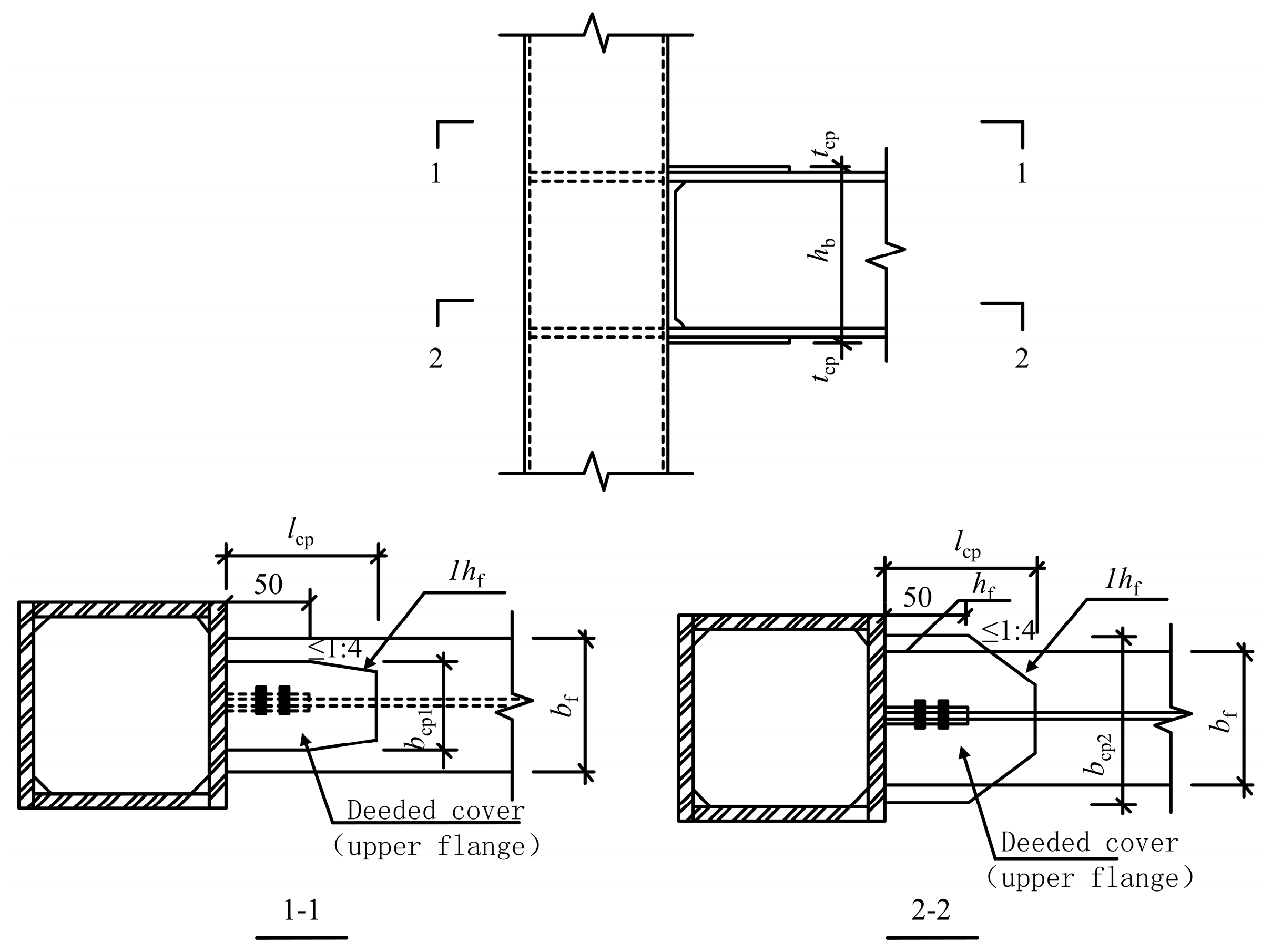
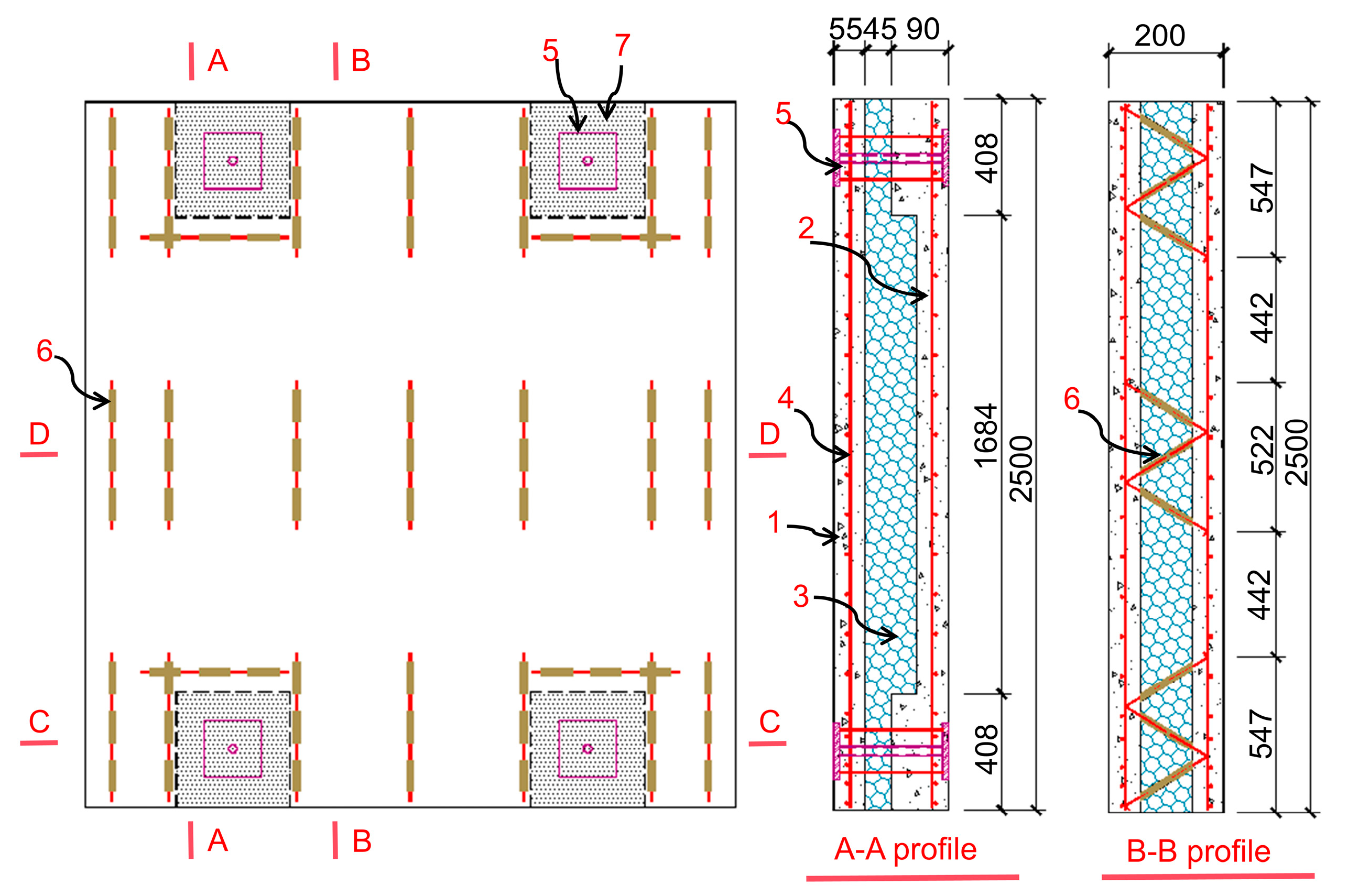
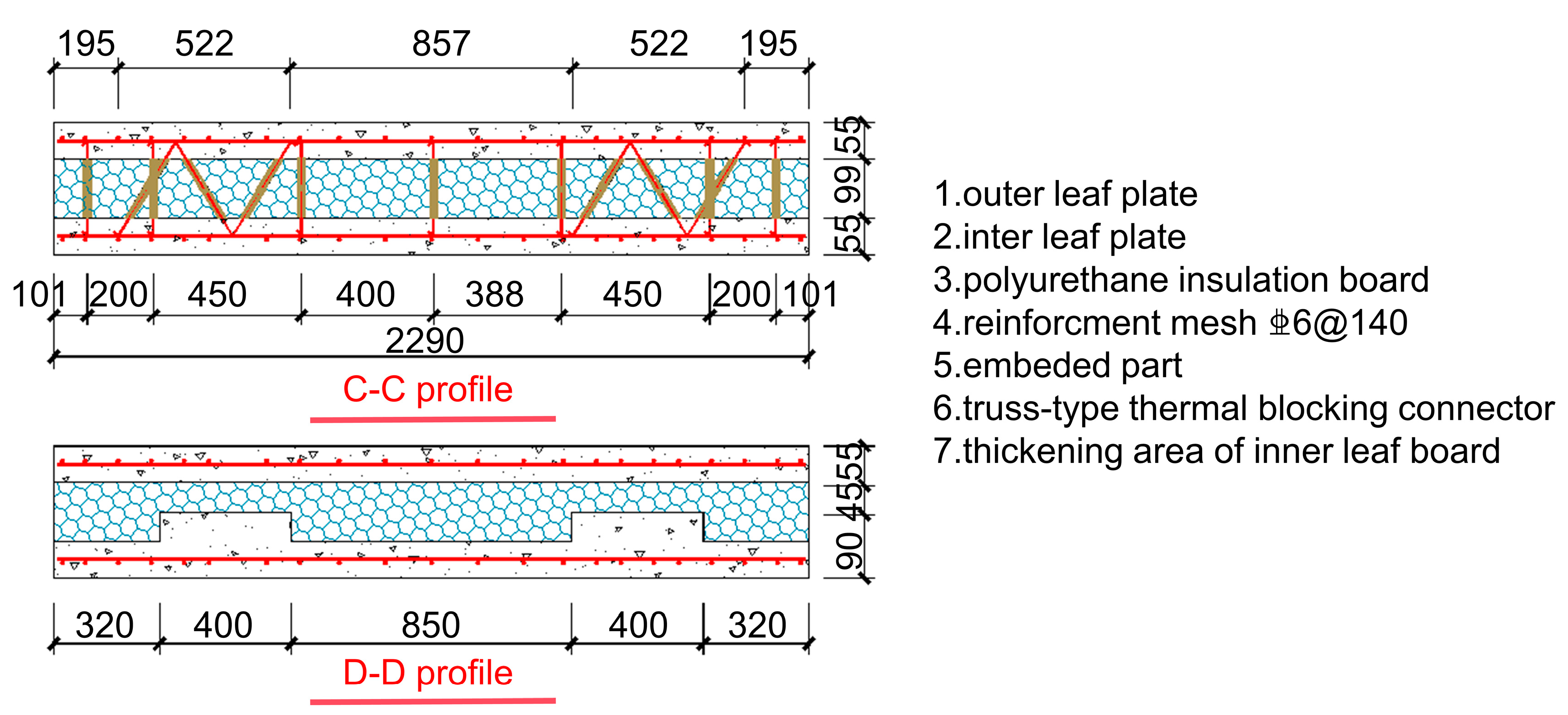
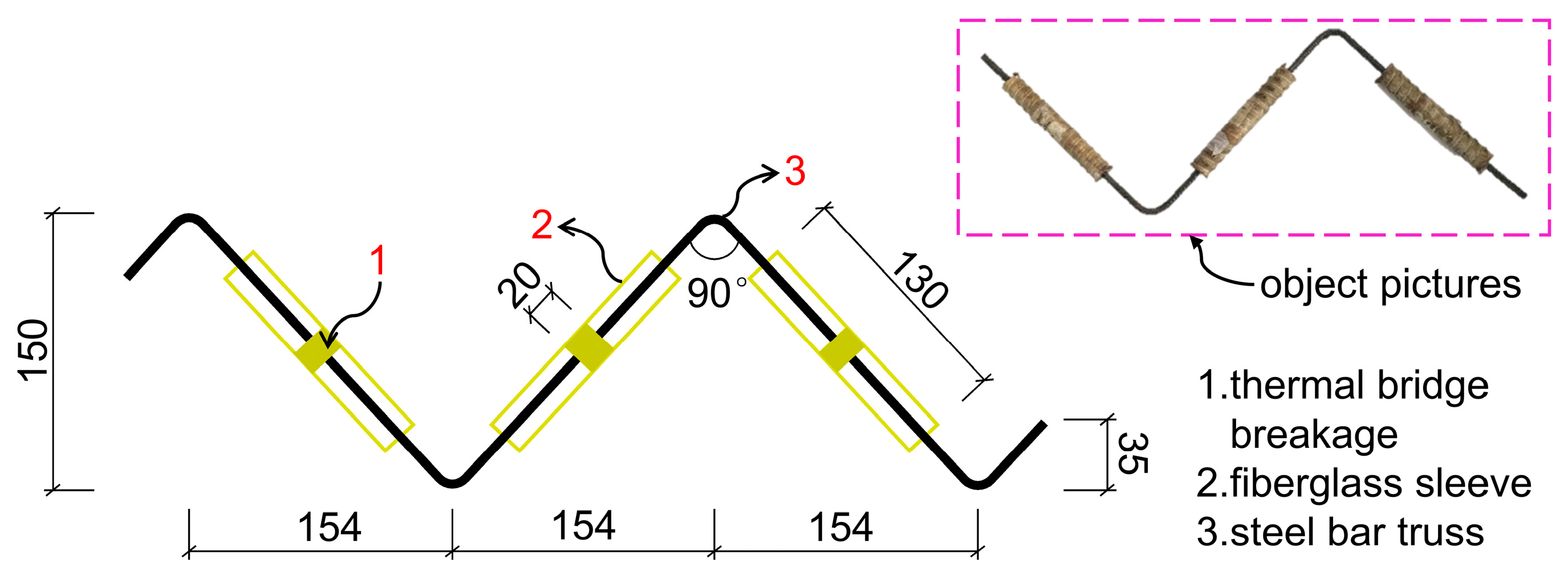
2.1. Specimen Design

We designed and numbered three single-layer and single-span full-scale specimens, SF, S-P1, and S-P2. The SF specimen consisted of a frame without a wallboard, while the S-P1 and S-P2 specimens included both frames and LCEW. The steel frame’s height was 3.27 m, and the span was 2.70 m. Square steel tube columns had a cross-section of H 200 × 200 × 12 and frame beams had a cross-section of H 220 × 175 × 8 × 12. The frame beams and frame columns were rigidly connected by welding the steel beam flanges and columns with groove butt welds and connecting the steel beam webs and columns with fillet welds. The position of the plastic hinge area at the beam end was far away from the beam–column connection position. In order to prevent damage to the connection weld, according to the “Technical Code for Steel Structures of High-rise Civil Buildings” (JGJ/99-2015) [30], a beam flange cover type connection was used, as shown in Figure 1, and the dimensions were calculated in accordance with Equations (1)–(4). The design of the web stiffening ribs for the frame beams was based on the manufacturer’s experience and, without using a specification, four web stiffening ribs of 8 mm thickness were used to prevent early local buckling of the web. An M30 grade 10.9 high-strength bolt connected the frame column and the reaction beam. The LCEW inner and outer leaf panels were 55 mm thick, with an XPS insulation board positioned in the middle for a total thickness of 200 mm. Tests arranged the reinforcement bars in two directions in the middle of the inner and outer leaf panels and used TBC. The LCEW of specimen S-P1 had TBC set vertically, while the LCEW of specimen S-P2 had TBC set both vertically and horizontally. Figure 2 displays the drawing of the steel frame specimen. Figure 3 displays the detail drawings of the LCEW. Figure 4 illustrates TBC. Figure 5 details the connection joints, and Figure 6 displays the composition materials of the non-sintered fly ash ceramsite lightweight concrete.
ι c p = ( 0.50 ~ 0.75 ) h b
b c p 1 = b f 3 t c p
b c p 2 = b f + 3 t c p
t s t f

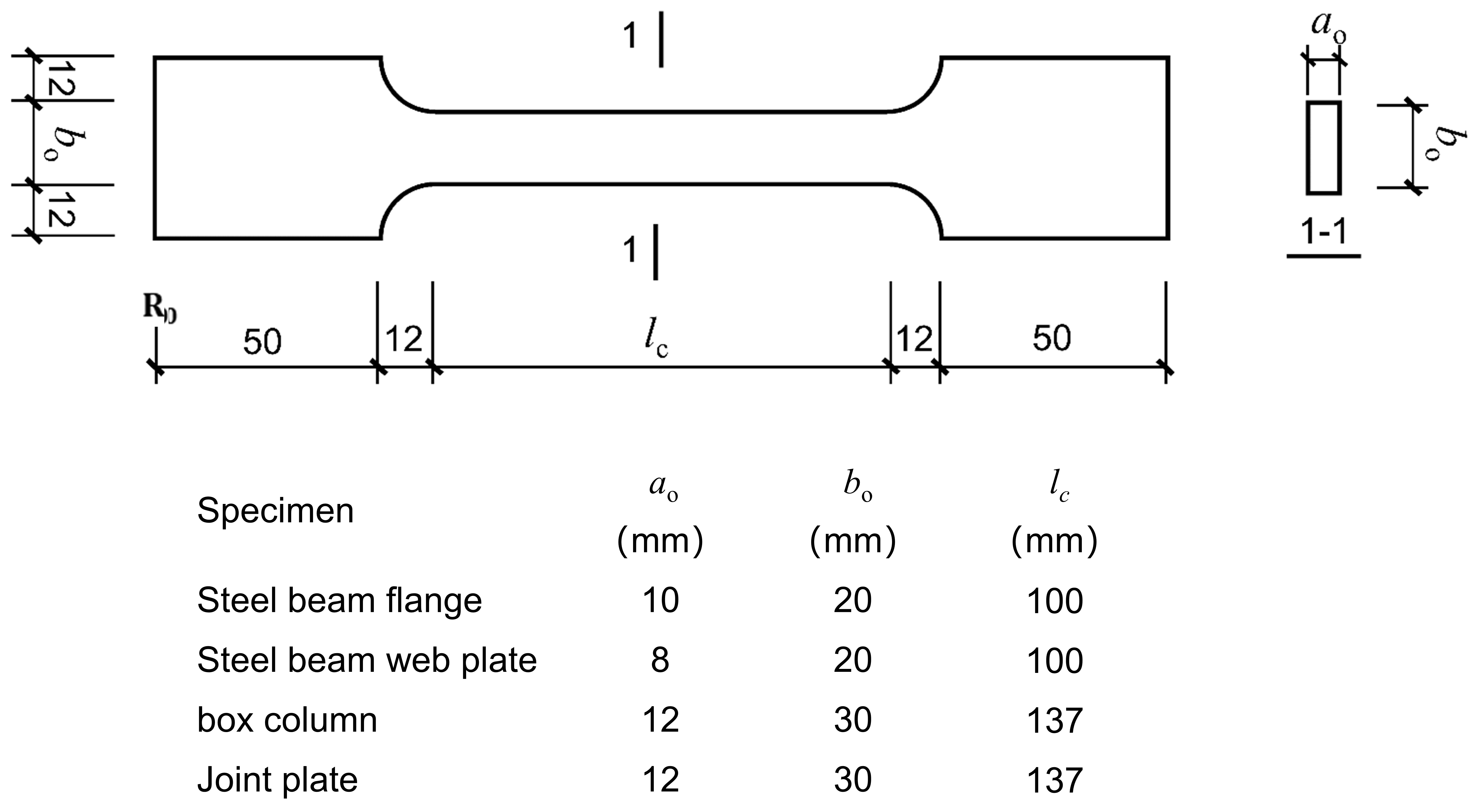
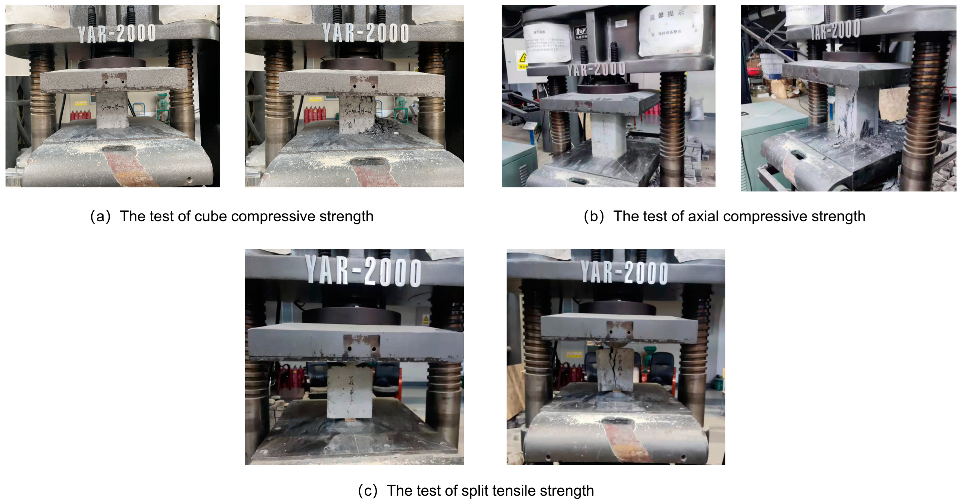
2.2. Material Properties

According to “Steel and steel products—Location and preparation of samples and test pieces for mechanical testing” (GB/T2975-2018) [31], three specimens were taken from different positions of steel members for the material performance test. The standard parts of material properties are shown in Figure 7, and the test results are shown in Table 1. The strength grade of all-lightweight concrete used in the project was LC35; according to the “Technical standard for lightweight aggregate concrete application” (JGJ/12-2019) [32], the optimized mix ratio design slump is suitable for the construction of non-sintered fly ash ceramsite full lightweight concrete. The cement adopts a grade of 42.5 ordinary Portland cement, light coarse aggregate, and light fine aggregate and non-sintered fly ash ceramsite and ceramic sand, with particle sizes of 5~16 mm and 3~4 mm, respectively. Admixtures include fly ash, polycarboxylate superplasticizer, and blast furnace slag. The slump index of concrete is 140~160 mm, which is greater than 120 mm. The mix ratio of non-sintered fly ash ceramsite lightweight concrete is shown in Table 2. According to “Test Methods and Standards for Mechanical Properties of Ordinary Concrete” (GB/T50081-2002) [33], the specimens were made and poured with cube specimens with side lengths of 10 mm and prism specimens with sizes of 150 mm × 150 mm × 300 mm and three samples in each group were poured. After curing for 28 days under standard conditions, cube compression and axial compression modulus tests were carried out on the specimens, respectively. The models were loaded with a 200T electro-hydraulic servo universal testing machine, the loading rate was set to 0.5 MPa/s, and the test results were averaged; the test process is shown in Figure 8. The mechanical properties of the all-lightweight concrete are shown in Table 3. The research team used a new lightweight concrete developed in-house, the material properties of which were not available in the specifications; therefore, the literature was not consulted.

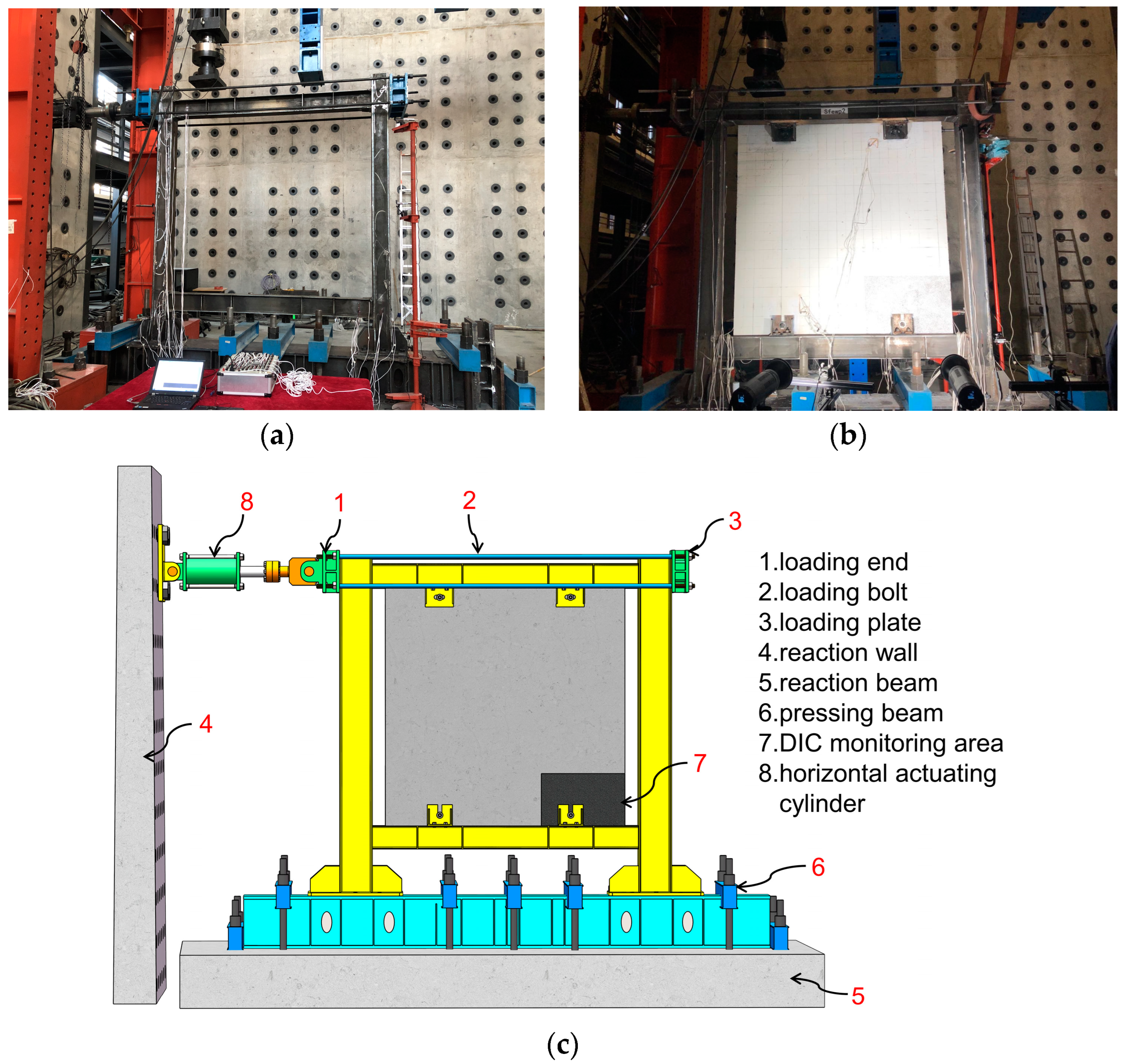
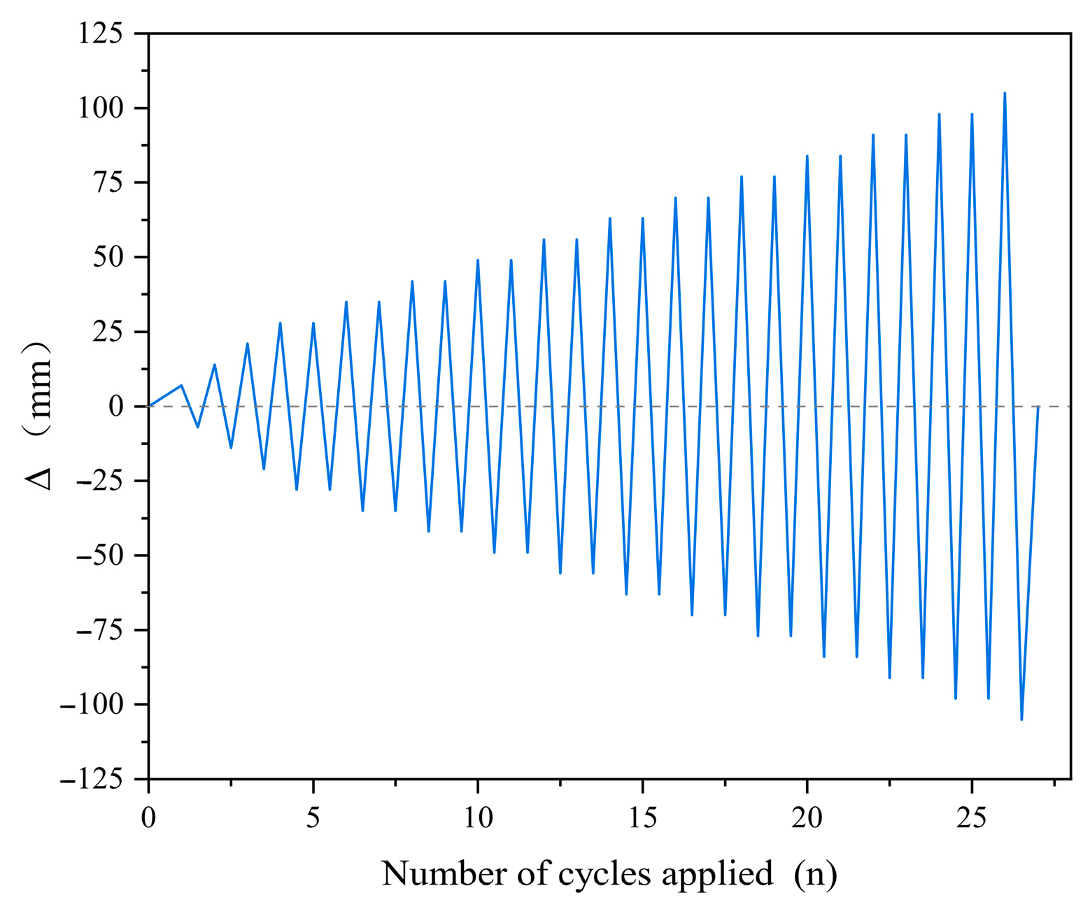
2.3. Test Setup and Test Program

This experiment was completed in the structural laboratory of Jilin Jianzhu University. The horizontal actuator of Hangzhou Bangwei, made in China, was used, with a maximum force value of 1000 kN and a total stroke of 500 mm. Four M30 tensioned loading bolts connected the loading end of the actuator and the loading plate for loading. Each column base was connected to the bottom beam through eight 10.9 grade M30 high-strength bolts. Four uniform pressure beams were set on the upper part of the reaction beam, and limit jacks were placed at both ends to prevent the specimen from slipping and overturning. Figure 9 shows the test setup.
The test employed the displacement control loading method. The actuator provided a quasi-static test for the specimen at a loading rate of 5 s/mm. The test used a grade difference of 7 mm (0.25 y). Each stage was cycled once before 28 mm (∆y), and each step was cycled twice after 28 mm (∆y). The loading system is shown in Figure 10. When one of the following conditions occurred, it was considered that the specimen lost its bearing capacity and stopped loading: (1) The connector was seriously deformed. (2) Someone pulled or cut off the long connecting bolt. (3) Wide cracks appeared in the wallboard. (4) The test load was reduced to less than 85% of the peak load. (5) The beam or column experienced severe local buckling, or the weld suffered tearing.
The arrangement of steel frame and concrete strain gauges, as well as acceleration and displacement sensors, is shown in Figure 11. Among them, the strain gauge S1~S28 was used to measure the circumferential strain, and the concrete strain was measured by the C1~C16 strain gauge. A displacement meter LVDT-1 was arranged on the outer side of the column in the middle of the joint region connecting the upper beam and column. The displacement meters LVDT2 and LVDT3 were arranged in the middle of the right column and the left column, respectively, to measure the displacement of the middle of the frame column during the loading process. The displacement meters LVDT4 and LVDT5 were arranged on the outer side of the column in the middle of the joint region connecting the lower beam and column. The displacement meters LVDT6 and LVDT7 were arranged at the top and bottom of the right side of the wallboard to observe the horizontal displacement of the wallboard. In Figure 11, C and LVDT represent the strain and displacement measuring points, respectively.

3. Experimental Study

3.1. Experimental Phenomena

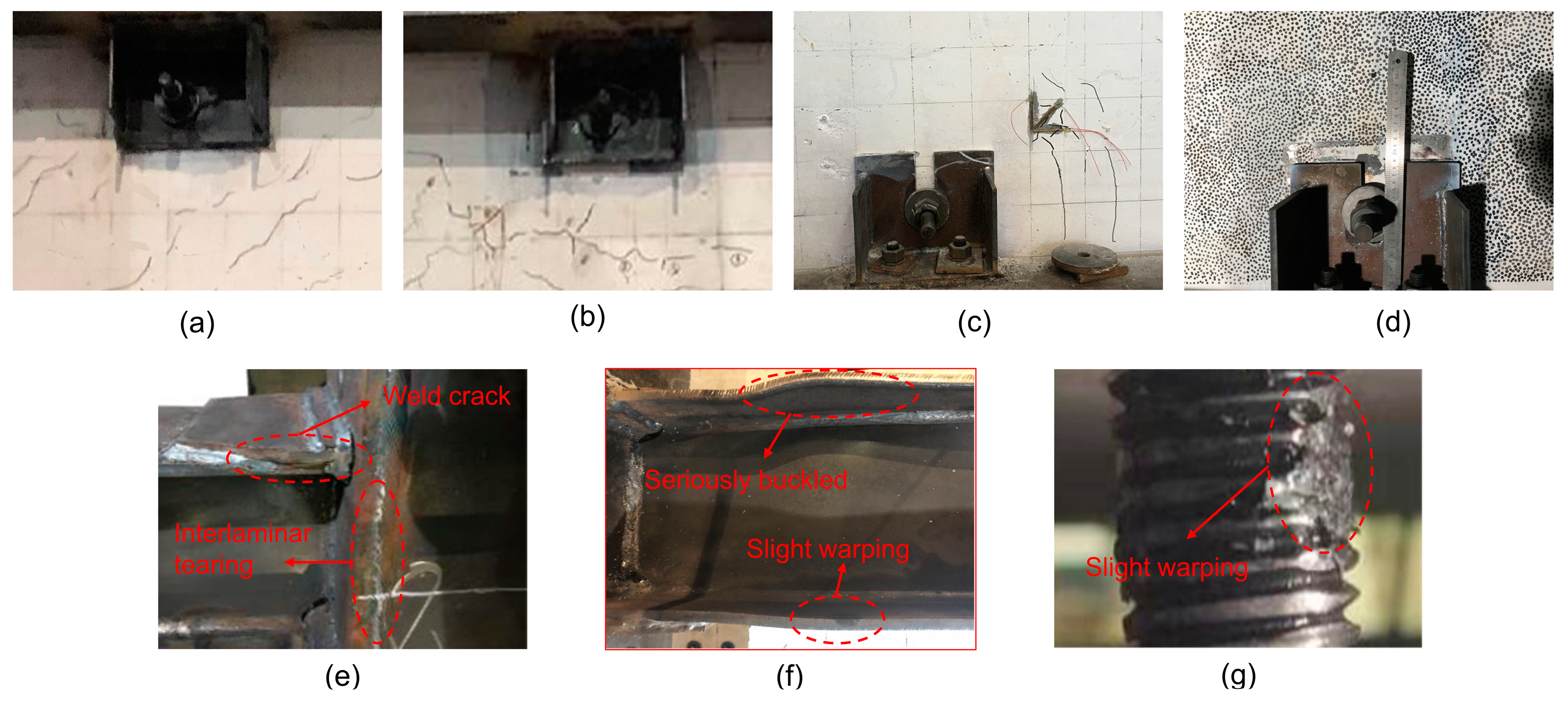
3.1.1. The Failure Phenomenon of Specimen SF

Specimen SF was in the elastic stage, and there was no apparent phenomenon at the initial loading stage. When the displacement reached the first cycle of 39 mm (θ ≈ 1/64, (θ is the inter-story displacement angle)), the upper flange of the left end of the top beam began to yield, located 0.25 times the height of the beam from the end of the reinforcement plate of the joint. After loading to the first cycle of 77 mm (θ ≈ 1/32), slight warping of the beam flange at the end of the reinforcement plate of the upper left joint and the lower right joint was observed. When loading to 91 mm (θ ≈ 1/27), the weld between the lower flange at the right end of the upper frame beam and the frame column cracked. Loaded to 98 mm (θ ≈ 1/25), the weld between the upper flange of the right end of the top frame beam and the frame column was torn. When the top frame beam was loaded to 105 mm (θ ≈ 1/24), the flange of the end of the reinforced plate at the left end of the top frame beam seriously buckled in the first cycle. During the second cycle, the column flange experienced interlaminar tearing in the thickness direction at the junction between the upper flange of the top frame beam and the column, leading to the completion of the test. When the column was unloaded to zero, there was significant residual deformation. The destruction phenomenon is shown in Figure 12.

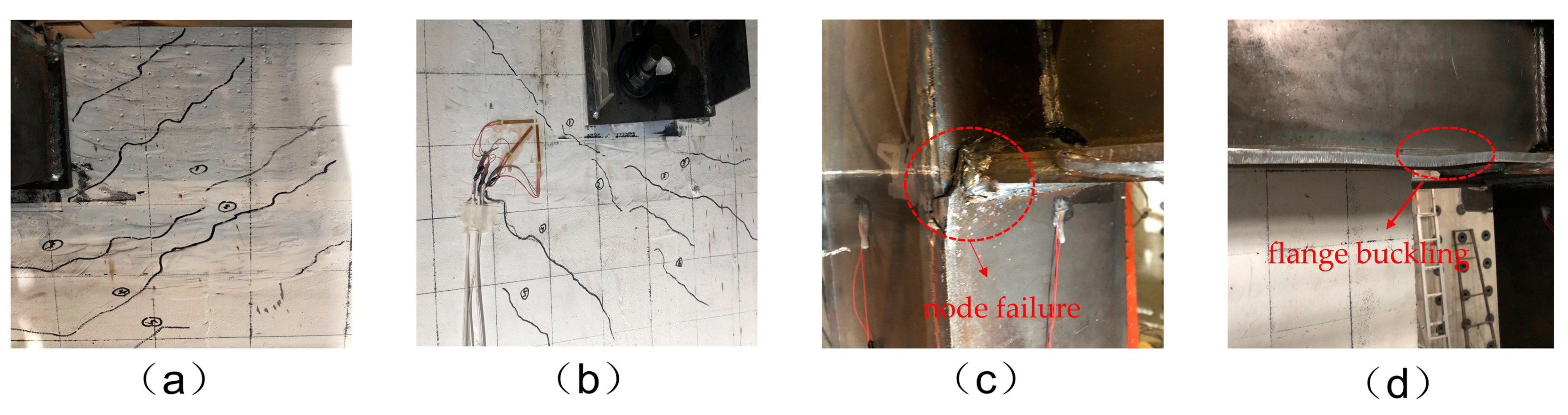
3.1.2. The Failure Phenomenon of Specimen S-P1

The friction between the gasket of the long screw bolt and the L-shaped joint produced a metallic sound during the initial loading stage, but the specimen showed no obvious phenomena. The first crack appeared near the No. 2 embedded part when the displacement was 42 mm. When loaded to 63 mm (θ ≈ 1/40), an oblique crack appeared near the No. 2 embedded part of the compression zone, which extended in the direction of a 45 inclination to the right. When loading the first cycle of 70 mm (1/36), there were numerous inclined cracks in the same direction as the first crack near the No. 2 embedded part. Simultaneously, we observed vertical shear cracks near the No. 3 embedded part. During the reverse loading process, the wallboard rotated obviously, and inclined cracks appeared on the right side of the No. 1 embedded part, extending along the direction parallel to the tension zone formed during positive loading. The reinforced plate’s end flange, located at the left end of the top frame beam, underwent slight deformation. When loading to the first cycle of 77 mm (θ ≈ 1/32), new cracks appeared near the No. 2 embedded part of the wallboard, and the old cracks expanded and extended simultaneously. When loaded to −77 mm (θ ≈ 1/32) for the second cycle, the weld of the joint between the right lower flange of the top frame beam and the frame column cracked. In the second cyclic loading, the weld at the joint between the stiffening plate at the right top frame beam and the frame column was torn when loaded to 86 mm (θ ≈ 1/30), and the end flange of the stiffening plate at the left end of the top frame beam severely buckled when loaded to 91 mm (θ ≈ 1/27). The test revealed severe wear on the thread of the long screw bolt. Figure 13 illustrates the specimen’s failure phenomenon.

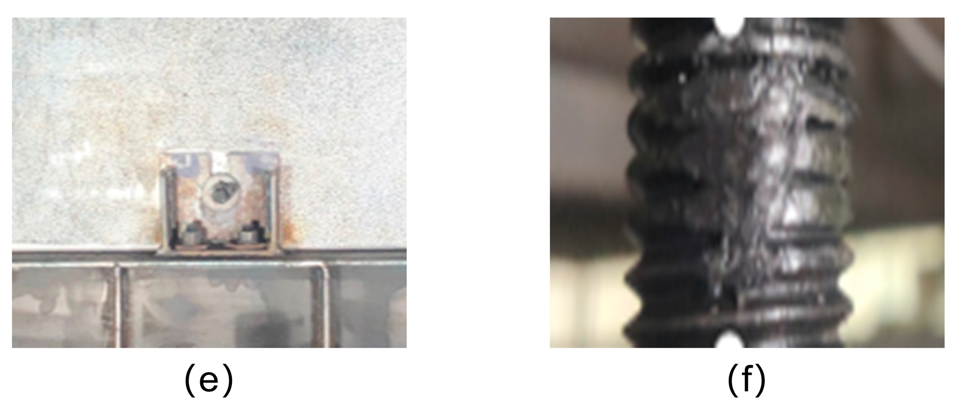
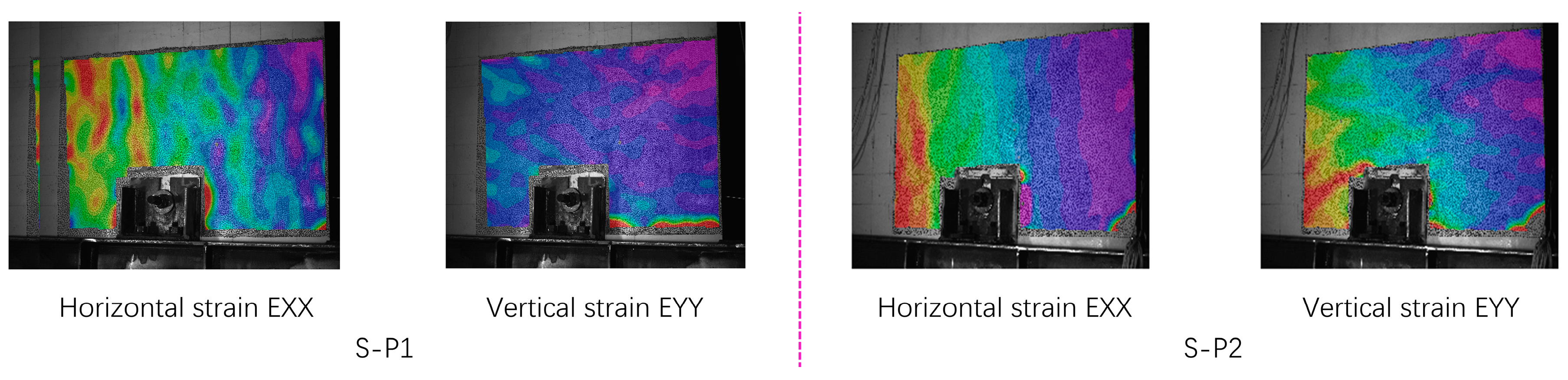
3.1.3. The Failure Phenomenon of Specimen S-P2

At the initial loading stage, there was no evident phenomenon in the specimen. In the first cycle of displacement loading to 42 mm, a tiny crack first appeared on the right side of the No. 3 embedded part. When loading to 77 mm (θ ≈ 1/32) for the first cycle, inclined cracks appeared on the right side of the No. 2 embedded part. After loading to 84 mm (θ ≈ 1/30) for the first cycle, the cracks near the embedded parts on the No. 2 side extended slightly, and two vertical downward shear cracks appeared near the embedded parts on the No. 3 side. During reverse loading, cracks appeared on the right side of the No. 1 embedded part. An evident rotation of the wallboard was observed. After loading to 91 mm (θ ≈ 1/27) for the first cycle, the weld of the joint between the lower left flange at the top frame beam and the frame column was torn, and a new crack appeared near the No. 2 side, which extended slightly during loading. Loading to 105 mm (θ ≈ 1/24) for the first cycle, the weld at the joint between the lower flange at the right end of the top frame beam and the frame column was torn. When loading to 112 mm (θ ≈ 1/22), the cracks around the embedded parts increased and the width expanded concurrently, and the end flange of the reinforcement plate at the right end of the top frame beam was seriously buckled, and the test was finished. The thread of the long screw bolt was not as severely worn as in specimen S-P1. The failure phenomenon of the specimen is shown in Figure 14.

3.2. Comparative Analysis of Test Phenomena

(1) Specimen SF was housed in a steel frame with a wedge-shaped reinforcement plate at the end of the frame beam. At the initial stage of loading, the specimen SF was in an elastic state. As the load gradually increased, the flange of the beam at the end of the reinforced cover plate yielded, causing the entire section of the steel beam to also yield. This resulted in the formation of a plastic hinge at the end of the reinforced cover plate. As the plastic hinges advanced, the warping of the flange at the end of the reinforced cover plate intensified, leading to a crack in the butt weld connecting the beam flange and column, and causing damage to the steel frame. The failure mode aligned with the design requirements for strong columns and weak beams as outlined in the “Code for Seismic Design of Building Structures” (GB/T50011-2011) [34].
(2) The failure of S-P1 and S-P2 specimens began with concrete surfaces cracking near the embedded parts. As the positive load increased, one or more inclined tensile bands formed, oriented approximately 45 degrees from the wallboard’s edge. As the load direction shifted, the tensile bands also shifted, and, concurrently, residual plastic deformation led to the formation of cross-tensile bands. Therefore, under the influence of the tension band, cracks all extended obliquely to 45 degrees. Then, the flange at the end of the stiffening plate of the top frame beam buckled slightly, and the weld at the beam–column joint tore until the flange seriously buckled. Following the loading, dense cracks formed around the embedded parts, with a narrow width and no formation of through cracks. Throughout the entire loading process, the embedded parts in the wallboard and the L-shaped joints between the wallboard and the steel frame maintained their elastic properties. The wallboard demonstrated strong mechanical performance, and the integrity and seismic performance of the steel frame met the relevant requirements for the elastic design of joints and embedded parts in the “Application Technical Specification for Precast Concrete Sandwich Thermal Insulation External Wall Panel” (DB3/T 5217-2022) [35].
(3) The horizontal TBC of specimen S-P2 improved the horizontal shear capacity of the concrete near the embedded parts and restrained the development of vertical shear cracks, as shown by the DIC strain distribution in Figure 15. The shear cracks in concrete near the center of the wallboard were less than those in specimen S-P1, but the effect was not apparent. The damage to the wallboard in specimen S-P2 was mostly caused by the unevenly placed horizontal TBCs and how they were laid out, which made it harder for the wallboard and frame structure to handle shear. Therefore, we suggest arranging the horizontal TBC in combination with the tension band position.

4. Results of Discussion

4.1. Hysteresis Curve and Skeleton Curve

The hysteretic curve of each specimen is shown in Figure 16. Comparing [36,37], the hysteresis curve of the specimen conforms to the development trend of the seismic hysteresis curve of similar structures, and the hysteresis loop is fuller without obvious pinch shrinkage phenomenon, which indicates that the composite wall panels in this test have a better seismic performance compared with the traditional wall panel structure. The following conclusions can be obtained by comparing and analyzing hysteretic curves:
(1) The hysteretic curves of all the specimens are shuttle-shaped and full, and the hysteretic curves coincide at the initial loading stage, which shows that all the specimens have better energy dissipation capacity. The slope of the curves gradually decreases as the displacement increases, showing that the stiffness of the specimens degenerates. This is due to the gradual evolution of the steel beam from the elastic stage to the elastic–plastic stage to the plastic stage under the action of cyclic horizontal loading, the frame damage caused by interlaminar cracking that occurred in the thickness direction of the column flange and the cracking of the butt weld at the flange of the beam–column connection node, and the reduction of the seismic capacity of the wall plate due to the cracking of the concrete on the wall plate, especially around the embedded parts.
(2) The hysteresis curves of specimens S-P1 and S-P2 are fuller than those of specimen SF, indicating that the wallboards contribute to the improvement in the stiffness and bearing capacity of the steel frame. The hysteresis curve area of specimen S-P2 under forward loading is slightly lower than that of specimen S-P1, while it is slightly larger under reverse loading, and the difference is not significant.
(3) The arrangement direction of the TBC diagonal member causes the hysteresis curve of specimen SP-2 to have misalignment in both positive and negative directions. The reason is that there are three diagonal members in TBC, and the number of diagonal members in tension and compression vary under the action of forward and reverse horizontal loads. Under a positive load, the members at both ends of the TBC are subjected to tension. When the horizontal load increases, the concrete of the leaf plate cracks, the anchoring bearing capacity of the tensile diagonal member in the leaf plate rapidly decreases, and the energy dissipation capacity of the wall board also decreases. However, under reverse load, the diagonal members at both ends are compressed, and the impact of concrete cracking on the anchoring bearing capacity is minimal, resulting in a difference in the hysteresis curve of S-P2 in both positive and negative directions.
According to the hysteresis curve test, the positive and negative load extreme points of each load cycle of each specimen are connected one by one to obtain the load-displacement skeleton curve of the model, as shown in Figure 17. The characteristic points and displacement values of the skeleton curve are measured by the farthest method, as shown in Table 4.
(1) The load and displacement increase linearly in the elastic stage. With the cracking of the wall and the slight buckling of the steel frame, the load and displacement show a non-linear relationship. The skeleton curve begins to bend towards the displacement axis, and the stiffness gradually decreases as the load increases. When the specimen yields in the plastic stage, the skeleton curve tends to be smooth. At this point, due to the continuous reduction in stiffness, the structural deformation accelerates until the peak load is reached and the load displacement gradually decreases.
(2) The average bearing capacity of positive and negative limit points is taken as the ultimate bearing capacity of SF, S-P1, and S-P2, which is 354.7 kN, 426.4 kN, and 433.1 kN, respectively. Compared with specimen SF, the bearing capacity of specimen S-P1 and specimen S-P2 increase by 20.21% and 22.10%, respectively, indicating that the bearing capacity of the structure with the LCEW is significantly improved.
(3) Compared with the specimen S-P1, the positive bearing capacity of the specimen S-P2 is not significantly improved, and the negative bearing capacity is increased by 5.12%, indicating that, although the setting of the TBC improves the ultimate seismic ability of the frame to a little extent, the impact is not significant.

4.2. Rigidity Degradation Analysis

The lateral stiffness K f w of the external wall panel steel frame structure in this test is mainly affected by the stiffness K f of the main steel frame, the in-plane lateral stiffness K w 1 of the wallboard, the stiffness K w 2 of the embedded parts, and the stiffness K w 3 of the L-shaped connection node, as shown in Figure 18. From the relationship between load and deformation, the lateral stiffness of the specimen can be simplified as a set of series-parallel force springs. K f w = K f + K w , K w is the total lateral stiffness of the wallboard.
K w = 1 1 K w 1 + 1 K w 2 + 1 K w 3 , K w < m i n K w 1 , K w 2 , K w 3 . It is known from the formula that when the wall panel embedded parts and L-type connection node stiffness is very large, K w = K w 1 . In this paper, the L-shaped connection joint and the embedded steel plate embedded in the concrete are designed to meet the elastic requirements of large earthquakes. So, the value of K w 2 is very large, remaining unchanged. However, the K w 2 value of the embedded part is mainly affected by the shear stiffness of the long threaded bolts.
Figure 19 shows the relationship curve between the horizontal displacement of the top of the wallboard and the horizontal displacement of the top of the steel frame by the No. 6 displacement meter of specimen SP-2; there is no relative displacement between the wallboard and the steel frame. The main sources of stiffness are K f and K w 1 . When the displacement is loaded to about +12 mm, a slight relative displacement begins to occur between the wallboard, and the steel frame long threaded bolts begin to bear the shear force. K w 2 is elastic stiffness. When the displacement is loaded from +40 mm to about +12 mm, the long threaded bolts contact with the hole wall of the horizontal long hole of the L-shaped connection node, the hole wall is squeezed, and, with the increase in displacement, the bolts are repeatedly squeezed and worn. K w 2 begins to change from elasticity to elastic-plasticity. At this time, the L-shaped connection joint is squeezed by the hole wall and forced to participate in the stiffness contribution, providing stiffness K w 3 .
The stiffness degradation curves of the three specimens obtained from the test are shown in Figure 20. Combined with the stiffness composition and the contribution of each stiffness during the loading period, the stiffness degradation of the specimens is analyzed. During the installation of the wallboard, the long threaded bolts are subjected to a small preload during the tightening process. In the early stage of loading, the existence of a preload creates static friction between the wallboard and the L-shaped connection node, and there is no relative slip. The initial secant stiffness of specimens SF, S-P1, and S-P2 is 6.55 kN/mm, 6.71 kN/mm, and 6.74 kN/mm, respectively. The initial secant stiffness ratios of specimens S-P1 and S-P2 to SF are 2.44% and 2.90%, respectively, indicating that the exterior wallboard has little effect on the elastic lateral stiffness of the steel frame structure under flexible connection conditions.
After continued loading, the stiffness degradation rate of specimens S-P1 and S-P2 is faster than that of empty frame SF. The main reason is that the static friction is gradually overcome until the displacement reaches about 12 mm. The stiffness of the three specimens is basically the same, mainly due to the stiffness of the steel frame itself. With the increase in displacement, the long threaded bolts began to shear, and the stiffness of S-P1 and S-P2 increases slightly. When loaded to 40~50 mm, the long threaded bolts contact the hole wall, the stiffness of the embedded parts of the wallboard and the L-shaped joints begin to provide stiffness, and the stiffness of the two specimens continues to rise. When the loading continues, micro-cracks begin to appear inside the wallboard, and the stiffness of the wallboard gradually decreases, but the stiffness of specimen S-P2 is always greater than that of specimen S-P1. This situation shows that the transversely arranged ties can inhibit the cracking of the wallboard near the embedded parts and improve the structural stiffness. The displacement continues to increase, and the structural stiffness continues to degrade. When the displacement reaches 77 mm, the concrete near the embedded parts of the bearing seriously cracks, the transverse TBC effect is completely lost, and the stiffness degradation of specimens S-P1 and S-P2 tends to be consistent.

4.3. Energy Dissipation Capacity Analysis

Energy dissipation is the ability of a structure to absorb energy through the yielding process of plastic hinges. The greater the energy dissipation of a structure, the greater its seismic capacity [38].
At the initial stage of loading, the energy dissipation curves of the three specimens basically coincide, indicating that the wallboard participates in the low degree of stress mainly consumed by the steel frame. As the displacement increases to the contact between the long threaded bolts of the upper connection and the hole wall of the L-shaped connection joint, the in-plane stiffness provided by the wallboard reaches its maximum value. The wallboard itself, the long threaded bolts, and the L-shaped connection joint participate in energy dissipation at the same time. The energy dissipation capacity of specimens S-P1 and S-P2 is stronger than that of SF. As the displacement continues to increase, the L-shaped connection joints and internal embedded parts of the specimens S-P1 and S-P2 are always elastic, and the energy dissipation capacity remains unchanged. The engraved long threaded bolts provide partial damping of energy dissipation under repeated fatigue, and the energy dissipation capacity is slightly improved. When loading to 85 mm, the energy dissipation capacity of S-P1 and S-P2 is 24.17% and 18.75% higher than that of SF. In the later stage of loading, the wallboard of the specimen is seriously damaged, and the energy dissipation capacity decreases. The three specimens all rely more on the plastic deformation of the steel frame to consume energy. It can be seen from the curve that the energy dissipation of the later specimen S-P1 is higher than that of specimen S-P2, indicating that the transverse TBC does not improve the energy dissipation capacity of the specimen. Energy dissipation capacity analysis is shown in Figure 21.

5. Conclusions

(1) The hysteresis curves of S-P1 and S-P2 are fuller than those of SF, indicating that the external LCEW wallboard contributes to the stiffness and bearing capacity of the steel frame. Compared with specimen SF, the bearing capacity of specimen S-P1 and specimen S-P2 increases by 19.98% and 22.12%, respectively.
(2) The transverse uniform arrangement of TBCs can only delay the crack opening, and, to give full play to its effect, it should be combined with the direction of the main tensile zone of the wall panels. The area of the hysteresis curve of specimen S-P2 under forward load is slightly smaller than that of specimen S-P1, while the area of the hysteresis curve under reverse load is slightly larger than that of specimen S-P1, and the difference is not significant, indicating that the transverse arrangement of TBCs does not have much effect on the stiffness of the frame.
(3) The long circular holes in the L-shaped connection plate play an important role in releasing the relative displacement between the wall panels and the steel frame, and the length of the holes should be reasonably valued. The LCEW wall panels in this paper do not participate in the structural energy dissipation at the beginning of loading. As the load increases, the energy dissipation capacity of S-P1 and S-P2 increases by 24.17% and 18.75%, respectively, over the pure frame structure. In the later stages of loading, due to severe concrete cracking, the wall panels have reduced energy dissipation capacity, and the hole still relies on the deformation of the steel frame.
(4) From the test failure phenomenon, the two specimens of the external LCEW are not seriously damaged when the concrete block falls off, indicating that the bearing capacity of the wallboard is good. Under repeated load, the long threaded bolts have wear phenomenon, and the safety factor should be improved.
(5) In order to promote the external LCEW to better adapt to the deformation of the steel frame structure, and to prevent the stiffness degradation curve from being unsatisfactory due to too tight installation of the long threaded bolts, it is recommended to install a rubber pad between the L-shaped joint and the wallboard to reduce the static friction force.

Author Contributions

Conceptualization, X.W.; methodology, X.W.; software, X.W. and H.S.; validation, X.W. and H.S.; formal analysis, X.W., H.S. and Y.L.; investigation, X.W.; resources, X.W.; data curation, Y.H.; writing—original draft preparation, H.S. and X.W.; writing—review and editing, X.W. and H.S.; visualization, H.S.; supervision, X.W.; project administration, X.W. All authors have read and agreed to the published version of the manuscript.

Funding

This research was funded by [Key R & D Project of jilin Provincial Science and Technology Department, grant number [20210203145SF] and the APC was funded by [W.X.].

Data Availability Statement

Data are contained within the article.

Conflicts of Interest

The authors declare no conflicts of interest.

References

  1. Lee, B.J.; Pessiki, S. Thermal performance evaluation of precast concrete three-wythe sandwich wall panels. Energy Build. 2006, 38, 1006–1014. [Google Scholar] [CrossRef]
  2. Mousa, M.A.; Uddin, N. Experimental and analytical study of carbon fiber-reinforced polymer (FRP)/autoclaved aerated concrete (AAC) sandwich panels. Eng. Struct. 2009, 31, 2337–2344. [Google Scholar] [CrossRef]
  3. Carbonari, G.; Cavalaro, S.H.P.; Cansario, M.M.; Aguado, A. Flexural behaviour of light-weight sandwich panels composed by concrete and EPS. Constr. Build. Mater. 2012, 35, 792–799. [Google Scholar] [CrossRef]
  4. Mastali, M.; Valente, I.B.; Barros, J.A.; Gonçalves, D.M. Development of innovative hybrid sandwich panel slabs: Experimental results. Compos. Struct. 2015, 133, 476–498. [Google Scholar] [CrossRef]
  5. Frazão, C.; Barros, J.; Toledo Filho, R.; Ferreira, S.; Gonçalves, D. Development of sandwich panels combining Sisal Fiber-Cement Composites and Fiber-Reinforced Lightweight Concrete. Cem. Concr. Compos. 2018, 86, 206–223. [Google Scholar] [CrossRef]
  6. Kinnane, O.; West, R.; Hegarty, R.O. Structural shear performance of insulated precast concrete sandwich panels with steel plate connectors. Eng. Struct. 2020, 215, 110691. [Google Scholar] [CrossRef]
  7. Zhu, K.; Zheng, X.; Zhang, C.; Chen, N.; Han, Y.; Yan, L.; Quaresimin, M. Compressive response and energy absorption of all-composite sandwich panels with channel cores. Compos. Struct. 2022, 289, 115461. [Google Scholar] [CrossRef]
  8. Fan, W.; Xie, R.; Davidson, M.; Yin, H.; Lai, K.; Wu, Q. Crashworthiness and energy absorption of UHPFRC-steel composite sandwich structures under impact loading. Compos. Struct. 2023, 311, 116813. [Google Scholar] [CrossRef]
  9. Wilden, H. PCI Design Handbook: Precast and Prestressed Concrete, 7th ed.; Prestressed Concrete Institute: Chicago, IL, USA, 2014. [Google Scholar]
  10. Oliveira, T.F.; de Carvalho, J.M.F.; Mendes, J.C.; Souza, G.Z.; Carvalho, V.R.; Peixoto, R.A.F. Precast concrete sandwich panels (PCSP): An analytical review and evaluation of CO2 equivalent. Constr. Build. Mater. 2022, 358, 129424. [Google Scholar] [CrossRef]
  11. O’Hegarty, R.; Kinnane, O. Review of precast concrete sandwich panels and their innovations. Constr. Build. Mater. 2020, 233, 117145. [Google Scholar] [CrossRef]
  12. Frankl, B.A.; Lucier, G.W.; Hassan, T.K.; Rizkalla, S.H. Behavior of precast, prestressed concrete sandwich wall panels reinforced with CFRP shear grid. PCI J. 2011, 56, 42–54. [Google Scholar] [CrossRef]
  13. Lameiras, R.; Barros, J.; Valente, I.B.; Azenha, M. Development of sandwich panels combining fibre reinforced concrete layers and fibre reinforced polymer connectors. Part I: Conception and pull-out tests. Compos. Struct. 2013, 105, 446–459. [Google Scholar] [CrossRef]
  14. Tawil, H.; Tan, C.G.; Sulong, N.H.R.; Nazri, F.M.; Sherif, M.M.; El-Shafie, A. Mechanical and Thermal Properties of Composite Precast Concrete Sandwich Panels: A Review. Buildings 2022, 12, 1429. [Google Scholar] [CrossRef]
  15. He, J.X.; Xu, Z.D.; Zhang, L.Y.; Lin, Z.H.; Hu, Z.W.; Li, Q.Q.; Dong, Y.R. Shaking table tests and seismic assessment of a full-scale precast concrete sandwich wall panel structure with bolt connections. Eng. Struct. 2023, 278, 115543. [Google Scholar] [CrossRef]
  16. Zhou, B.; Si, Q.; Zong, L.; Wang, B. Seismic performance analysis of steel frames with FCP composite external wall. Structures 2022, 39, 86–97. [Google Scholar] [CrossRef]
  17. Cui, Y.; Hao, H.; Li, J.; Chen, W.; Zhang, X. Structural behavior and vibration characteristics of geopolymer composite lightweight sandwich panels for prefabricated buildings. J. Build. Eng. 2022, 57, 104872. [Google Scholar] [CrossRef]
  18. Fan, M.; Guo, H.; Li, S.; Wang, H.; Wang, Z.; Liang, G. Experimental and numerical study of prefabricated steel frame with integrated wall panels. J. Constr. Steel Res. 2023, 201, 107746. [Google Scholar] [CrossRef]
  19. Benayoune, A.; Samad, A.A.; Ali, A.A.; Trikha, D.N. Response of pre-cast reinforced composite sandwich panels to axial loading. Constr. Build. Mater. 2007, 21, 677–685. [Google Scholar] [CrossRef]
  20. Benayoune, A.; Samad, A.A.; Trikha, D.N.; Ali, A.A.; Ellinna, S.H.M. Flexural behaviour of pre-cast concrete sandwich composite panel—Experimental and theoretical investigations. Constr. Build. Mater. 2008, 22, 580–592. [Google Scholar] [CrossRef]
  21. Ahmad, I.; Goh, W.I.; Samsuddin, S.; Mohamad, N.; Rahman, M.H.A.; Samad, A.A.A. Structural Behaviour of Precast Lightweight Foamed Concrete Sandwich panel (PLFP) with Double Shear Truss Connectors under Eccentric Load: Preliminary Result. Adv. Mater. Res. 2013, 795, 414–418. [Google Scholar] [CrossRef]
  22. Woltman, G.; Tomlinson, D.; Fam, A. Investigation of various GFRP shear connectors for insulated precast concrete sandwich wall panels. J. Compos. Constr. 2013, 17, 711–721. [Google Scholar] [CrossRef]
  23. Zhao, J.; Chen, R.; Wang, Z.; Pan, Y. Sliding corner gusset connections for improved buckling-restrained braced steel frame seismic performance: Subassemblage tests. Eng. Struct. 2018, 172, 644–662. [Google Scholar] [CrossRef]
  24. Bai, J.; Chen, H.; Zhao, J.; Liu, M.; Jin, S. Seismic design and subassemblage tests of buckling-restrained braced RC frames with shear connector gusset connections. Eng. Struct. 2021, 234, 112018. [Google Scholar] [CrossRef]
  25. Jia, M.; Lu, D.; Guo, L.; Sun, L. Experimental research and cyclic behavior of buckling-restrained braced composite frame. J. Constr. Steel Res. 2014, 95, 90–105. [Google Scholar] [CrossRef]
  26. Zhang, H. Contrastive Analysis of Two Connection Modes of Enclosure Wallboards and Steel Frames. IOP Conf. Ser. Mater. Sci. Eng. 2019, 563, 032050. [Google Scholar] [CrossRef]
  27. Zhao, J.; Yan, L.; Wang, C.; Zhou, Y.; Chen, R.; Chan, T.M. Damage-control design and hybrid tests of a full-scale two-story buckling-restrained braced steel moment frame with sliding gusset connections. Eng. Struct. 2023, 275, 115263. [Google Scholar] [CrossRef]
  28. Fang, M.J.; Wang, J.F.; Li, G.Q. Shaking table test of steel frame with ALC external wall panels. J. Constr. Steel Res. 2013, 80, 278–286. [Google Scholar] [CrossRef]
  29. Yossef, M.; Chen, A. A solution considering partial degree of composite action for insulated sandwich panels with general configuration flexible shear connectors. Eng. Struct. 2018, 162, 135–150. [Google Scholar] [CrossRef]
  30. JGJ 99-2015; Technical Specification for Steel Structure of High-Rise Civil Buildings. Ministry of Housing and Urban-Rural Development of the People’s Republic of China: Beijing, China, 2015.
  31. GB/T 2975-2018; Steel and Steel Products—Location and Preparation of Samples and Test Pieces for Mechanical Testing. State Administration for Market Supervision and Administration, China National Standardization Management Committee: Beijing, China, 2018.
  32. JGJ/T 12-2019; Technical Standard for Lightweight Aggregate Concrete Application. Ministry of Housing and Urban-Rural Development of the People’s Republic of China: Beijing, China, 2019.
  33. GB/T 50081-2002; Standard for Test Methods of Mechanical Properties on Ordinary Concrete. The Southern Baptist Theological Seminary: Louisville, KY, USA, 2003.
  34. GB/T 50011-2010; Code for Seismic Design of Buildings. China Building Industry Press: Beijing, China, 2016.
  35. JGJ/T 458-2018; technical standard for application of precast concrete external wall panels. Ministry of Housing and Urban-Rural Development: Beijing, China, 2018.
  36. Chalarca, B.; Gabbianelli, G.; Bedoya-Ruiz, D.; Nascimbene, R. Experimental and numerical simulation dataset of a ferrocement wall subjected to fully-reversed cyclic load test. Data Brief 2024, 53, 110095. [Google Scholar] [CrossRef] [PubMed]
  37. Nicoletti, V.; Arezzo, D.; Carbonari, S.; Gara, F. Detection of infill wall damage due to earthquakes from vibration data. Earthq. Eng. Struct. Dyn. 2023, 52, 460–481. [Google Scholar] [CrossRef]
  38. Araby, M.Z.; Rizal, S.; Abdullah Afifuddin, M.; Hasan, M. Deformation Capacity of RC Beam-Column Joints Strengthened with Ferrocement. Sustainability 2022, 14, 4398. [Google Scholar] [CrossRef]
Figure 1. Beam flange cover type connection.
Buildings 14 02224 g001
Figure 2. Details of steel frame specimens.
Buildings 14 02224 g002
Figure 3. LCEW drawing.
Buildings 14 02224 g003aBuildings 14 02224 g003b
Figure 4. Truss-type thermal blocking connector (TBC).
Buildings 14 02224 g004
Figure 5. Details of connection node.
Buildings 14 02224 g005
Figure 6. Composition materials of non-sintered fly ash ceramsite lightweight concrete.
Buildings 14 02224 g006
Figure 7. Details of standard parts.
Buildings 14 02224 g007
Figure 8. Test process.
Buildings 14 02224 g008
Figure 9. Test setup. (a) Test setup of the steel frame specimen; (b) test setup of the specimen with wallboard; (c) model diagram of the test setup.
Buildings 14 02224 g009
Figure 10. Loading protocol.
Buildings 14 02224 g010
Figure 11. Layout of the measuring points. (a) For steel frame. (b) For wallboard.
Buildings 14 02224 g011
Figure 12. Failure phenomenon of SF specimen. (a) Interlaminar tearing of panel; (b) severe local buckling of beam flange; (c) residual deformation of frame column.
Buildings 14 02224 g012
Figure 13. Failure phenomenon of S-P1 specimen. (a) Cracks near No. 1 embedded part; (b) cracks near No. 2 embedded part; (c) cracks near No. 3 embedded part; (d) the bolt rotates at No. 4 embedded part; (e) weld tearing at frame–column joint; (f) local buckling of beam flange; (g) slight warping.
Buildings 14 02224 g013
Figure 14. Failure phenomenon of SF specimen. (a) Cracks near No. 1 embedded part; (b) cracks near No. 2 embedded part; (c) beam–column joint tearing; (d) local buckling of beam flange; (e) the bolt rotates at No. 4 embedded part; (f) slight warping.
Buildings 14 02224 g014aBuildings 14 02224 g014b
Figure 15. DIC strain distribution.
Buildings 14 02224 g015
Figure 16. Hysteretic curve.
Buildings 14 02224 g016
Figure 17. Load-displacement skeleton curve.
Buildings 14 02224 g017
Figure 18. Series-parallel force springs.
Buildings 14 02224 g018
Figure 19. Relationship between the upper displacement and the load of specimen S-P2.
Buildings 14 02224 g019
Figure 20. Stiffness degradation curve.
Buildings 14 02224 g020
Figure 21. Energy dissipation capacity analysis.
Buildings 14 02224 g021
Table 1. Mechanical properties of steel.
SpecimenThicknessYield StrengthTensile StrengthElongation
t/mmfy/MPafu/MPaA/%
Steel beam web plate836748321.6
Steel beam flange10350.148021.3
Box column12354473.220.8
Joint plate12352.1476.620.9
Rebar6 (diameter)426.7566.520.3
Table 2. Concrete mix proportion ratio.
CementCeramicPottery SandCoal Fly AshSlagWater Cement RatioWater Reducing Agent
(kg)(kg)(kg)(kg)(kg)(%)
50055052535250.45
Table 3. Mechanical properties of all-lightweight concrete.
MaterialDry Apparent DensityCube Compressive StrengthAxial Compression StrengthSplit Tensile StrengthElastic Modulus
(kg/m3)(MPa)(MPa)(MPa)(MPa)
All-lightweight concrete167443.938.12.92.26 × 104
Table 4. Characteristic points and displacement values of the skeleton curve of each specimen.
Specimen NumberLoading DirectionYielding PointPeak LoadLimiting PointDisplacement Ductility Coefficient
Δy/mmθyPy/kNΔmax/mmθmaxPmax/kNΔu/mmθuPu/kNμΔ = Δuy
SFforward 51.821/4828284.081/30343.3149.641/17291.802.89
reverse50.391/49288.990.861/28366112.691/22311.12.24
SP-1forward 59.111/42340.1104.81/24452.5144.291/17384.632.44
reverse44.191/57307.390.291/28400.3105.831/24340.262.39
SP-2forward51.771/48299110.81/23445.4199.151/13378.593.85
reverse51.51/48309.498.081/25420.8179.021/14357.683.48
Disclaimer/Publisher’s Note: The statements, opinions and data contained in all publications are solely those of the individual author(s) and contributor(s) and not of MDPI and/or the editor(s). MDPI and/or the editor(s) disclaim responsibility for any injury to people or property resulting from any ideas, methods, instructions or products referred to in the content.

