Article

Optimizing the Support System of a Shallow Buried Tunnel under Unsymmetrical Pressure

1
School of Resources and Safety Engineering, Central South University, Changsha 410083, China
2
School of Civil Engineering, Sun Yat-Sen University, Zhuhai 519082, China
*
Authors to whom correspondence should be addressed.
Buildings 2024, 14(6), 1825; https://doi.org/10.3390/buildings14061825
Submission received: 16 May 2024 / Revised: 4 June 2024 / Accepted: 13 June 2024 / Published: 15 June 2024
(This article belongs to the Special Issue The Damage and Fracture Analysis in Rocks and Concretes)

Abstract

:
In the construction process of tunnel inlet sections, the rock mass can sustain unsymmetrical pressure due to asymmetrical terrain on the two sides of the tunnel. The fact that the inlet sections are usually under shallow buried conditions with strongly weathered rock mass exacerbates the issue. This paper discusses optimization strategies of the initial support of a shallow buried tunnel based on the analytical results of asymmetrical loading characteristics. Numerical simulation is performed with particle flow code (PFC) using the Jianshanji tunnel project as an example. The simulation results show that the bench excavation has slightly less total deformation than the full-section excavation but the deformation range is wider, especially in the tunnel arch. Both lining support and slope reduction treatments can effectively improve rock deformation, with lining support demonstrating better performance in controlling deformation and adjusting stress distribution. Based on the simulation results, the bench excavation and lining support are used in the actual project, and the corresponding optimization control measures were adopted to address deformation issues, including crushed-stone backfilling for compression resistance, advanced grouting reinforcement, and grouting. The field data show that the tunnel stability is effectively improved by adopting the optimization schemes, which further validates the effectiveness of the proposed unsymmetrical control method.

1. Introduction

In transportation constructions, tunnels are in many cases the optimal choice for traversing mountainous terrain due to their capacity to reduce travel time and mitigate environmental damage. Constrained by the terrain, tunnel entrance sections are often subjected to unfavorable geological conditions. One such condition widely observed is an unsymmetrical pressure, which is attributed to the uneven distribution of the thickness of the tunnel’s overlying layer [1,2]. Coupled with the shallow overlying layer, tunnel construction disturbances, and heavy rainfall, uneven pressure on the two sides of the tunnel increases the likelihood of face sliding, collapse, as well as cracking of initial support structures [3,4,5,6].
As a result of the combined effects of shallow burial and unsymmetrical terrain [7,8,9,10,11], the initial stress field of the surrounding rock significantly differs from conventional tunnels [12,13,14,15,16]. Many scholars have analyzed the characteristics of tunnel portals. For example, Daraei [17] made changes to the Heybat Sultan twin-tunnel project according to V.E. principles prior to the commencement of the excavations, selected the optimal water outlet scheme, and evaluated the stability of the slope by numerical analysis. Asli [18] used the finite-element method to numerically analyze the tunnel portal section. Considering the results of the 3D numerical analysis, the existing portal was enlarged and excavation of the third tube was started, and the results showed that the improvement effect was good. Daraei [19] uses a practical multi-graph to determine the sequential excavation method of the tunnels, which can provide an effective tool for selecting the sequential excavation method (SEM) and predicting the ground behavior in the primary phase of designing tunnels and also during excavation. Meanwhile, during the construction process, continuous excavation and support operations lead to constantly changing the boundary conditions of the rock mass, which results in highly complex mechanical responses of the surrounding rock [20,21,22,23,24,25,26]. Such features have drawn many scholars’ close attention. Xiao et al. [27] conducted laboratory experiments and integrated on site monitoring data to comprehensively investigate the mechanical deformation mechanisms of tunnels subjected to unsymmetrical pressure after support. Ma [28] utilized numerical simulation methods to analyze the effects of the construction of highway tunnels under unsymmetrical pressure with small clearances on both the tunnel itself and the surrounding rock. Mao et al. [29] took into account the synergistic effects between the tunnel and the slope and established an evaluation model system for shallowly buried and terrain-biased tunnels. Miao et al. [30] studied the mechanism of significant deformation in shallowly buried and terrain-biased tunnels after initial support using a combination of on site monitoring, laboratory rock expansion tests, and three-dimensional numerical simulation. Due to the limitations of on site monitoring and experimental methods, an in-depth understanding of the characteristics and deformation patterns of the tunnel under unsymmetrical pressure often relies on numerical simulation techniques [31,32,33,34,35,36,37,38]. Many scholars have carried out relevant research through numerical simulation. Gao et al. [39] utilized the FEM to establish a numerical model for the entrance section of shallowly buried and terrain-biased tunnels and investigated the distribution patterns of stress during tunnel excavation. Mehrabi et al. [40] established a numerical model using DEM and studied the deformation curve of the soil mass on the tunnel surface. Kielbassa and Duddeck [41] established three-dimensional finite-element models for the sectional excavation steps of circular and non-circular tunnels for analysis and derived an equivalent two-dimensional simulation method based on the results of the analysis. Sterpi D et al. [42] studied the progressive instability of shallow buried tunnels using numerical analysis methods of formation structure softening and material softening of surrounding rock. Chu et al. [43] simulated the influence of different formation parameters on the mechanical behavior of small clear-distance tunnels.
According to the literature survey, a comprehensive investigation into the deformation characteristics and control of the entrance section of shallowly buried tunnels under unsymmetrical pressure combining DEM and engineering practices has not been thoroughly conducted. Using the JianShanJi tunnel engineering project as an example, this paper analyzes the main influencing factors of terrain-biased deformation in the entrance section of shallowly buried tunnels after excavation and proposes effective measures for deformation control. Based on the on site geological information, a numerical model is established using PFC. The failure characteristics of the tunnel after initial support under four construction conditions are analyzed—full-face tunneling method, bench excavation method, lining support treatment, and slope cutting. The numerical results are compared with the measured data on site after initial support. Based on the numerical results, optimal construction methods and support schemes for the tunnel are proposed. The research results have important reference value for the construction and research of similar engineering projects.

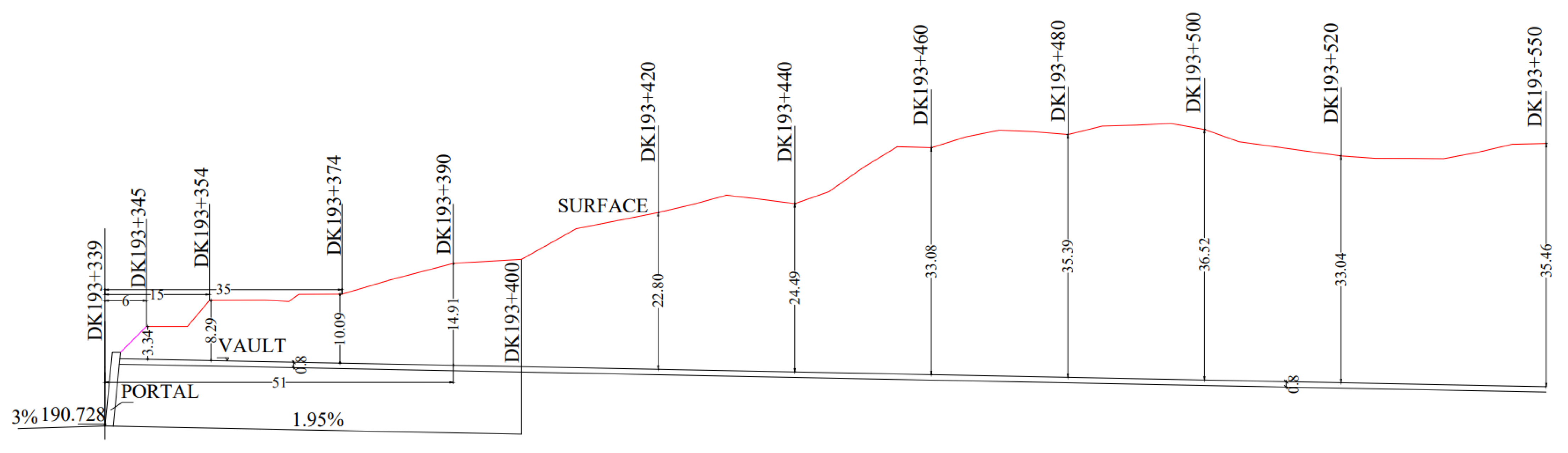
2. Overview of the Tunnel’s Entrance Section

2.1. Geological and Geotechnical Conditions

The Jianshanji tunnel project is located in the mountainous area of central Guangdong, China. The entrance section of the tunnel is located at the foot of a mountain slope, and the dip direction of the tunnel is 135°. The surface is silty clay, and the thickness is 5~20 m. The tunnel passes through a bedrock of dacite porphyry, with a partial intrusion of granite. The granite is completely weathered, gray and white, most of the minerals have weathered into sandy soil, and the original rock can be identified with a thickness of 10~30 m. The joint fissure is very developed, the fracture surface is partially stained with iron, and the layer thickness is 5~15 m. Groundwater is locally developed. The maximum buried depth of the tunnel inlet section is 25~40 m, most of the cave body is located in the granite all-strong weathering layer, the roof of the tunnel is easy to collapse, and the support should be strengthened in the design. The poor integrity of the surrounding rock makes the occurrence of sudden disasters such as water inrush and collapses highly possible. Geotechnical properties are shown in Table 1.

2.2. Tunnel Entrance Conditions

The settlement deformation occurred at the entrance of tunnel DK193 + 380, and the depth of the covering layer in the settlement area was 12.48 m. The geological survey was carried out by China Railway Fourth Survey and Design Institute Group Co., Ltd., located in Wuhan, Hubei Province, China, using XY-100 vertical shaft hydraulic geological exploration rig. The longitudinal geological profile and tunnel cross-section are shown in Figure 1 and Figure 2.
Figure 3 illustrates the cross-section of the tunnel at the entrance section after excavation, including the initial support of the upper bench. It is evident that varying degrees of initial support deformation has occurred on the left side of the tunnel, and the arch foot of the upper step is obviously squeezed to the right. The monitoring data indicate severe deformation in the entrance section of the tunnel: the maximum cumulative settlement deformation of the tunnel centerline section is 53.2 cm, and the maximum cumulative settlement of the left arch foot of the upper step is 112.1 cm.
The deformation of the temporary inverted arch before the excavation of the lower bench of the tunnel can also be observed (Figure 4a). The inward deformation of the surrounding rock in the horizontal direction makes the temporary inverted arch bulge in batches with an arch height of about 30–40 cm. Additionally, on site monitoring results show that both left and right arch feet of the upper bench are in a suspended state. It is also observed that the sidewalls of the secondary lining have experienced a certain degree of cracking. Specifically, two diagonal cracks, each measuring 2.0–2.5 m in length, were observed on the left sidewall, while three similar cracks were observed on the right sidewall, as shown in Figure 4b.
Together with the excavation-induced deformation, the surface of the slope also experiences varying degrees of settlement deformation. As depicted in Figure 5, surface deformations induced cracks and voids on the left slope of the tunnel; moreover, water seepage has been observed in the rock outside the trench ditch of the tunnel, forming hanging water cavities due to long-term water infiltration, resulting in voids in the slope.

3. Numerical Simulation

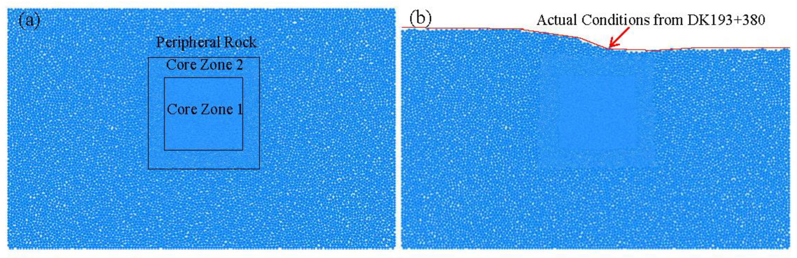
3.1. Establishment of the Numerical Model

The numerical model of the entrance of the Jianfengshan tunnel is established using particle flow code (PFC). A two-dimensional plane strain model with the dimensions 100 m × 60 m is constructed and gravity is applied to the particles as the force on the tunnel. The boundary position is greater than three times the diameter of the tunnel. The tunnel excavation width is 12.69 m, and the excavation height is 12.48 m. To obtain more precise results, the particle radius in the “core zone 2” of 30 m × 28 m around the tunnel is reduced to 0.5 times the radius of the outer particles, and in the “core zone 1” of 20 m × 15 m, the particle radius is further reduced to 0.2 times the radius of the outer particles, as shown in Figure 6a. The slope surface of the numerical model is defined based on the actual ground line data of pile No. DK193 + 380. This is realized by removing particles above the ground line, followed by elastic solution iterations until the entire system reaches a state of force equilibrium. A close resemblance between the simulated results and the actual geometry of the slope is ensured, as shown in Figure 6b.
The micro-contact between particles follows the PBM contact model. The calculation parameters are selected with reference to the calibration results of similar cases [44], and the specific parameters are obtained by engineering analogy, as shown in Table 2. While R m a x denotes the maximum particle radius of the peripheral rock; R m i n denotes the maximum particle radius of the peripheral rock; ρ signifies the model density; E C stands for the elastic modulus of the linear part in the PBM (Particle Bond Model); k n / k s signifies the stiffness ratio of the linear part in the PBM; E ¯ c indicates the elastic modulus of the bonding part in the PBM; k ¯ n / k ¯ S represents the stiffness ratio of the bonding part in the PBM; ϕ ¯ represents the friction angle in the PBM; σ ¯ c signifies the tensile strength in the PBM, and  τ ¯ C denotes the shear strength in the PBM.

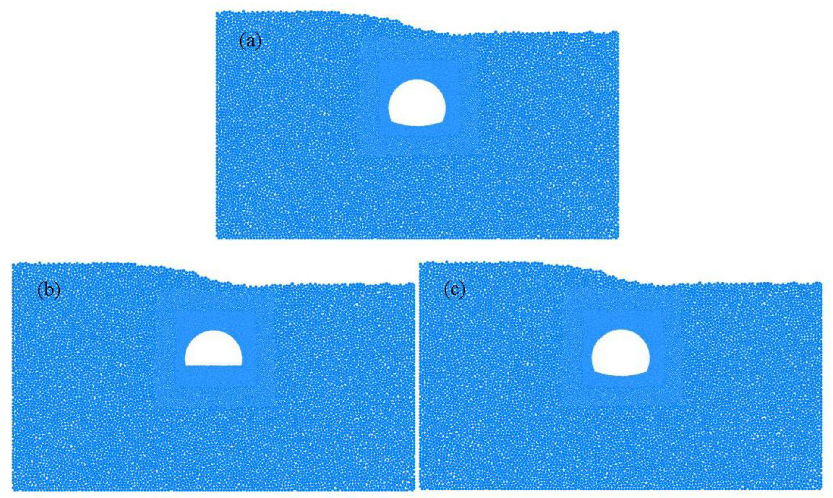
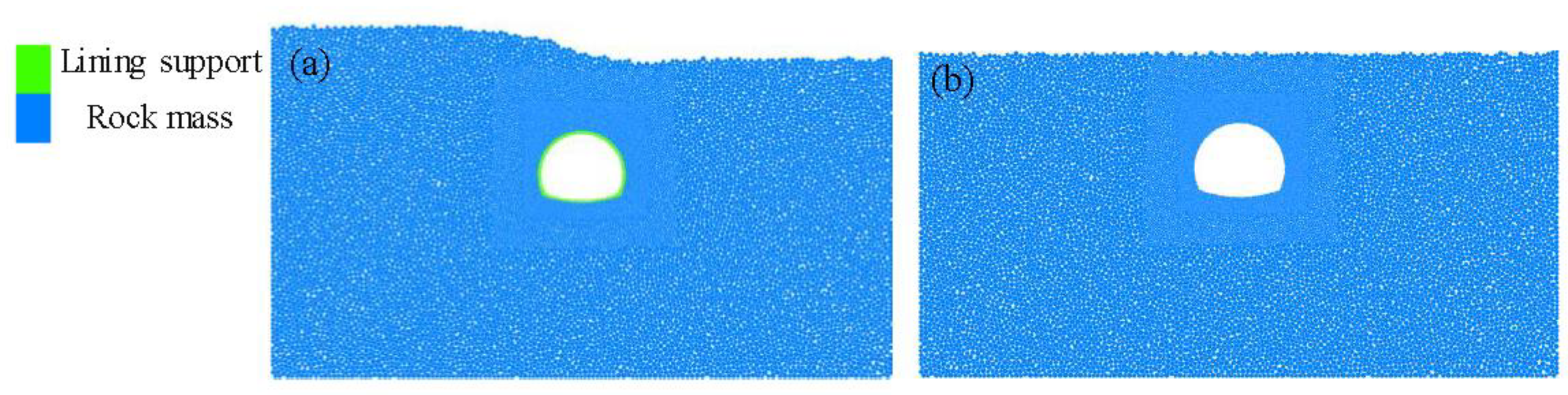
3.2. Modelling Schemes

To compare the effects of the different excavation methods, two approaches are modeled: a one-time removal of all particles inside the excavation region of the model (Figure 7a), and a stepwise removal of the particles inside the excavation region (Figure 7b,c). These two approaches correspond to the full-section excavation method and bench excavation method, respectively.
To investigate the applicability of reinforcement measures in relieving the unsymmetrical pressure, numerical simulations are also conducted with lining support (Figure 8a) and slope reduction (Figure 8b), respectively. The lining support model aims to enhance the load bearing capacity of the tunnel structure. For the lining support in this model, the elastic modulus and bond modulus of the linear part of the PBM are 30 times those of the rock mass, and the tensile and shear strength of the PBM are 10 times those of the rock mass. In addition, the thickness of the lining structure is the drawing provided by the design unit. On the other hand, the slope reduction model mitigates the effect of uneven stresses by decreasing the slope of overlying strata. During the excavation process in the above numerical models, measurements are made at eight locations at the periphery of the tunnel’s cross-section using the Fish language embedded in PFC to record the stress changes in the surrounding rock of the tunnel (Figure 9).

3.3. Simulation Results

3.3.1. Deformation Characteristics of the Surrounding Rock

The displacement contours of the surrounding rock after excavation are shown in Figure 10. The following pattern of the deformation in the surrounding rock can be summarized:
(1)
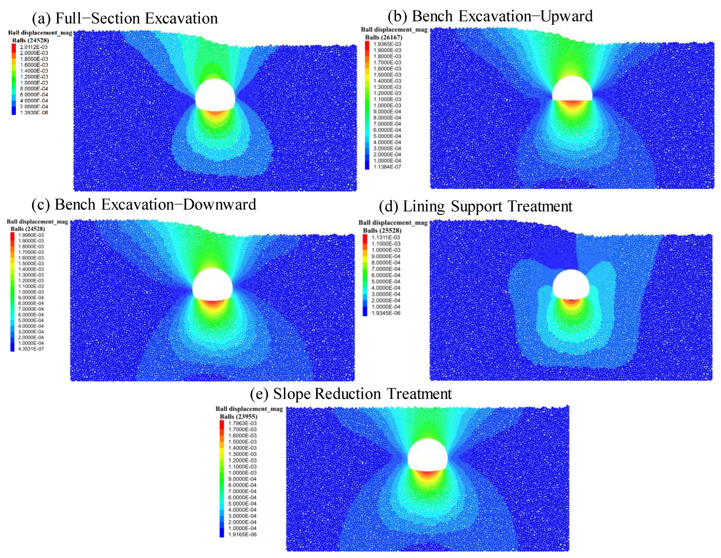
For both the full-section excavation model and bench excavation model, the deformation is most prominent at the arch. The maximum deformation values of the tunnel under full-section excavation and bench excavation are 2.01 mm and 1.99 mm, respectively, occurring at the bottom of the tunnel, while the deformation at side walls is relatively small. The total deformation around the tunnel caused by bench excavation is slightly smaller than that caused by full-section excavation;
(2)
The surrounding rock deformation caused by bench excavation has a wider range than that caused by full-section excavation, especially at the arch of the tunnel. This reflects the influence of frequent disturbance from bench construction on the stability of surrounding rock, where the range of unloading deformation of the surrounding rock is exacerbated;
(3)
Lining support treatment and slope reduction treatment can significantly reduce the overall deformation in the surrounding rock. The maximum deformation values of the tunnel under lining support treatment and slope reduction treatment have reduced to 1.13 mm and 1.80 mm, respectively. It should be noted that the lining support can greatly reduce the deformation in the rock mass above the arch;
(4)
Due to the influence of unsymmetrical pressure, the deformation of rock mass on the upper left side of the tunnel is larger than that on the upper right side. Especially after lining support treatment, the deformation of the rock mass on the left upper side of the tunnel is well controlled.
The vertical displacement contours of the surrounding rock after excavation are shown in Figure 11, where the following patterns can be observed:
(1)
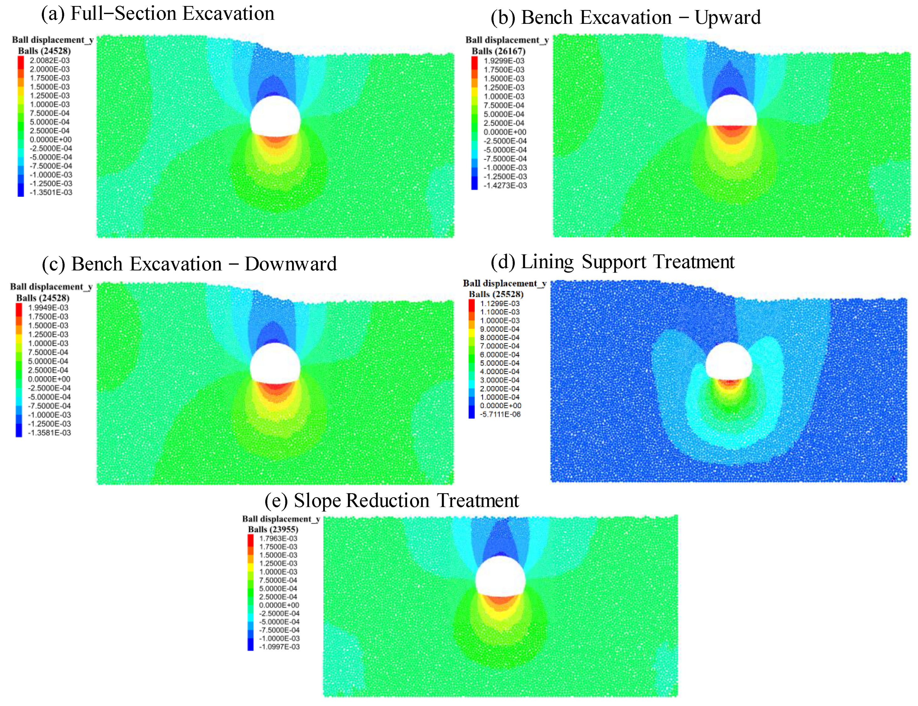
After tunnel excavation, the crown settlement and uplift of the inverted arch occur, with the absolute value of the maximum uplift displacement greater than that of the crown settlement. No significant difference can be found in the maximum vertical displacement between the full-section and bench excavation: the maximum crown settlement at the crown is 1.35 mm for both methods, while the maximum uplift displacement at the inverted arch is 2.01 mm and 2.00 mm, respectively;
(2)
Lining support treatment and slope reduction treatment significantly reduce the vertical deformation of the surrounding rock. The maximum settlement at the top of the crown is 0.00057 mm and 1.10 mm for the lining support treatment and slope reduction treatment, respectively, and the maximum uplift at the inverted arch is 1.13 mm and 1.80 mm, respectively;
(3)
Under lining support treatment and slope reduction treatment, the maximum settlement of the tunnel surrounding rock is 0.4% and 81.5% of that under full-section excavation, respectively; the maximum uplift of the tunnel surrounding rock is 56.2% and 89.5% of that under full-section excavation, respectively. Therefore, it can be observed that lining support treatment has a better effect in suppressing the vertical deformation of the surrounding rock.
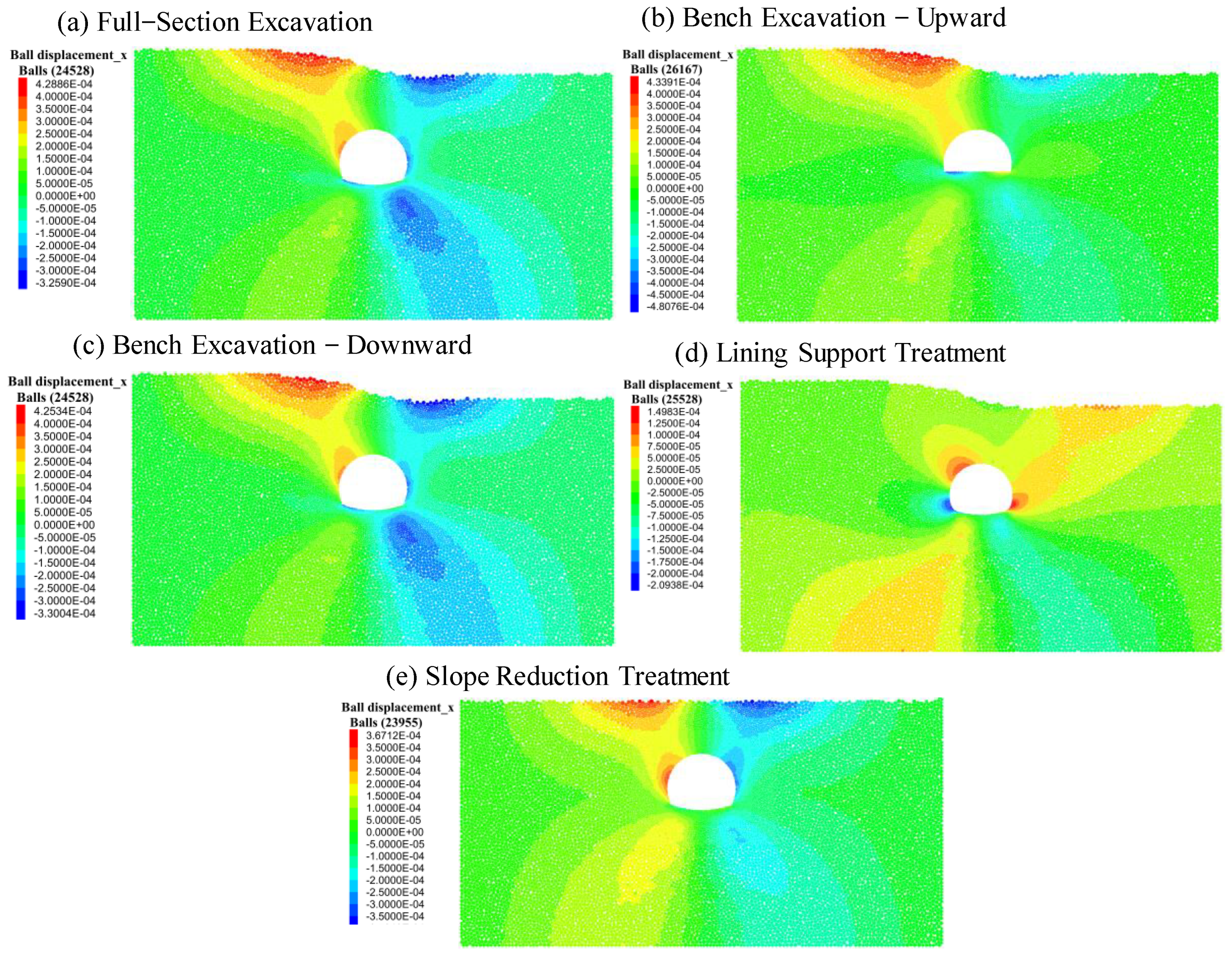
The horizontal displacement contours of the surrounding rock after excavation are depicted in Figure 12, where the following patterns are concluded:
(1)
The rock mass converges toward the inside of the tunnel after excavation, where the maximum displacement is found at the crown shoulder of the tunnel for both full-section and bench excavation methods. Additionally, the absolute value of displacement at the left shoulder exceeds that at the right shoulder, as a result of the unsymmetrical pressure. After full-section and bench excavation, the maximum displacement at the left shoulder is 0.429 mm and 0.434 mm, respectively, and the maximum displacement at the right shoulder is 0.326 mm and 0.330 mm, respectively. The difference in maximum horizontal displacement between the two excavation methods is insignificant;
(2)
Lining support treatment and slope reduction treatment can significantly suppress the deformation in the X-direction of the surrounding rock. After full-section and bench excavation, the maximum displacement at the left shoulder is 0.150 mm and 0.367 mm, respectively, and the maximum displacement at the right shoulder is 0.209 mm and 0.350 mm, respectively;
(3)
Under lining support treatment and slope reduction treatment, the maximum convergence at the right shoulder of the tunnel surrounding rock is 64.1% and 107.3% of that under full-section excavation, respectively. The maximum convergence at the left shoulder of the tunnel surrounding rock is 40.0% and 85.5% of that under full-section excavation, respectively. It is evident that compared to the slope reduction treatment, lining support treatment demonstrates superior capability in suppressing the deformation of the surrounding rock in the X-direction;
(4)
Due to the influence of unsymmetrical pressure, the maximum displacement of rock mass in the X direction on the left side of the ground after full-section excavation and bench excavation is larger than that on the right side. Lining support treatment significantly reduces the difference in the maximum displacement of ground rock mass, while slope reduction treatment makes the displacement nephogram basically a symmetrical distribution.

3.3.2. Stress Characteristics of the Surrounding Rock

As a discrete-element software primarily designed for granular materials, PFC does not directly support the output of stress contour maps. Therefor in this chapter, real-time monitoring of stress and data collection are made through the eight monitoring points at key locations of the tunnel, as shown in Figure 9.
The monitoring data of the vertical stress at various locations before and after tunnel excavation are presented in Table 3, where the following patterns can be deduced:
(1)
The vertical stress levels at the top and bottom of the tunnel are reduced by excavations. Specifically, the vertical stress at the top decreases by 14.0% and 14.3% for full-section excavation and bench excavation respectively, and at the bottom, it decreases by 21.8% for both excavation methods. Correspondingly, the vertical stress levels at the left and right sidewalls increase to 187.0% and 186.5% of the pre-excavation levels for the left sidewall, and 178.7% and 178.1% for the right sidewall. The vertical stress levels at the crown remain relatively unchanged. This indicates that the redistributed vertical stress caused by excavation mainly concentrates on the tunnel sidewalls;
(2)
The vertical stress at the top of the tunnel increases by 100.7% and 127.6%, respectively, after lining support and slope reduction treatments compared to pre-excavation levels. Correspondingly, the vertical stress at the bottom decreases by 48.2% and 20.6%, respectively. After slope reduction treatment, the vertical stress on both left and right sidewalls increases, respectively, to 166.9% and 150.5% of the pre-excavation levels. However, after lining support treatment, the vertical stress on both left and right sidewalls decreases to 84.2% and 82.1% of the pre-excavation levels, respectively;
(3)
Both the lining support and slope reduction treatments have effectively caused redistribution of vertical stress around the surrounding rock, resulting in a more uniform distribution and, thus, enhancing the overall stability of the tunnel. According to the obtained data, lining support treatment is more effective than slope reduction treatment.
The horizontal stress data obtained at different monitoring points before and after tunnel excavation and treatment are presented in Table 4. The findings are as follows:
(1)
A notable increase in horizontal stress levels at the top and bottom of the tunnel has been recorded after excavation. Compared to pre-excavation levels, the horizontal stress at the top increases by 14.0% and 14.3%, respectively, for the full-section excavation and bench excavation, while at the bottom, the increase is 21.8% for both excavation methods. Correspondingly, there is a significant decrease in horizontal stress along the left and right sidewalls of the tunnel, with reductions of 53.0% and 52.7% on the left side, and 56.3% and 56.0% on the right side, respectively, for the full-section excavation and bench excavation. The horizontal stress at the crown remains relatively unchanged. This indicates that the excavation has caused the concentration of horizontal stress in the surrounding rock mass at the top and bottom of the tunnel;
(2)
Following lining support treatment, the horizontal stress decreases to 58.8% at the top and increases to 108.6% at the bottom of the tunnel, compared to full-section excavation. After slope reduction treatment, the horizontal stress decreases to 98.8% at the top, while the horizontal stress at the bottom remains unchanged. Additionally, there is an increase in horizontal stress along the left and right sidewalls of the tunnel after lining support treatment, with increases to 258.7% and 239.8%, respectively. However, after slope reduction treatment, there is a decrease in horizontal stress along the left and right sidewalls, with reductions to 86.0% and 90.6%, respectively;
(3)
Both lining support treatment and slope reduction treatment effectively result in the favorable redistribution of horizontal stress in the surrounding rock mass, with lining support treatment exhibiting better results than slope reduction treatment.

4. Optimization of the Reinforcement

4.1. Optimization Approaches for Reinforcement

Based on the on site measurements/observations and numerical simulation presented in the previous sections, the deformation patterns in the entrance section of the tunnel can be attributed to the combined effects of topographic conditions and construction schemes. Specifically, due to the significantly inclined slope with loose rock mass above the tunnel roof, the pressure of the deep buried side of the tunnel is significantly greater than that of the shallow buried side, which leads to the unsymmetrical pressure on the tunnel. In addition, stress redistribution induced by tunnel excavation aggravates the uneven pressure condition by causing excessive stress concentration in certain locations in the surrounding rock. Therefore, proper support and reinforcement should be applied to share the excessively concentrated stress so that a more uniform stress distribution can be formed in the surrounding rock mass. In view of the above-mentioned analysis, the following measures are implemented to enhance tunnel stability:
(1)
Based on the numerical simulation results, the bench excavation approach, rather than full-section excavation, was chosen for tunnel excavation. Field exploration revealed a more pronounced fissure development, higher levels of rock fragmentation, and poorer rock strength than initially anticipated; consequently, the double-bench excavation method employed in the numerical simulation was further refined into a three-bench excavation method;
(2)
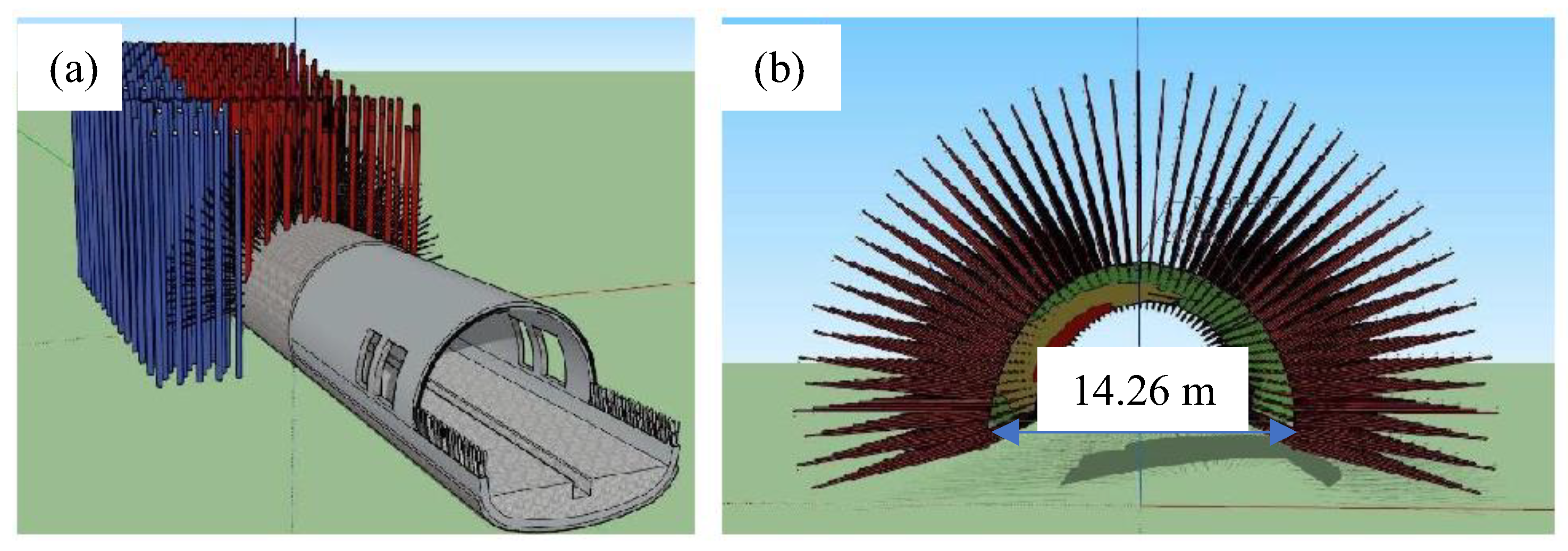
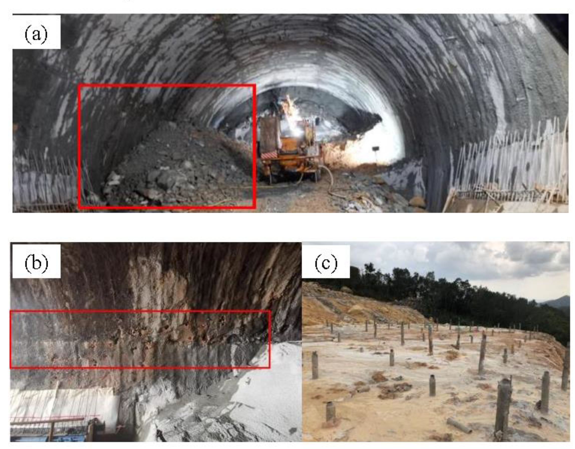
Carrying out the lining support treatment: This involved employing backfilling with crushed stones to counteract the pressure. During the secondary lining, we monitored the displacement of the mountain body at the entrance and carried out temporary internal support; the surface was reinforced by sleeve valve grouting (Figure 13a), while conduct radial dual-pipe grouting was used inside the tunnel to reinforce the weak foundations (Figure 13b). In addition, a Φ89-hole long pipe shed and a Φ42 advanced small pipe (type II) were used to implement advanced support and replace arches in intrusion sections.
(3)
Treatment for the uplift of the inverted arch: A static cone penetration test was performed on the inverted arch at the bottom of the tunnel to determine the bearing capacity and ensure the stability of the closed-loop initial support system. Temporary vertical support was set before the excavation of the lower bench, with additional foot anchors added to each steel frame on the left side. After the backfill on the excavation face, advanced grouting reinforcement needed to be carried out at the arch foot on the left and right sides of the upper bench;
(4)
Treatment for surface settlement: Mortar injection was carried out to stabilize the surface from possible voids (Figure 14). Underground grouting technology was utilized to fill the voids so the compactness of the strata was improved and settlement was reduced. The slope was reinforced around the tunnel to prevent settlement caused by geological disasters such as landslides.

4.2. Evaluation of the Reinforcement Effects

The optimized reinforcement measures were adopted in the entrance section of the tunnel. To evaluate the applicability of the optimized reinforcement, measurements of horizontal convergence, vault convergence, and surface settlement were carried out. In order to ensure the comprehensiveness and accuracy of monitoring, the surface subsidence monitoring points were arranged symmetrically along the middle line of the tunnel. Seven monitoring points were set up with a horizontal spacing of 3 m near the tunnel center line, then the horizontal spacing between the monitoring points was increased to 5 m, and another eight monitoring points were set up. Each monitoring section was equipped with 15 measuring points. Based on the DK193+380 monitoring results, the convergence and convergence rates are plotted against time, as shown in Figure 15 and Figure 16.
From Figure 15, it can be observed that the peripheral convergence has experienced three stages including a rapid growth stage, a slow growth stage, and a stable stage. The rapid increase in the convergence on the 20th monitoring day is the result of sudden continuous rainfall, which led to excessive unsymmetrical pressure and corresponding unsymmetrical deformation on the left side of the tunnel. After taking measures such as backfilling with tunnel debris, the convergence was stabilized again. As shown in Figure 16, there are sudden changes in the peripheral convergence rates of the bench excavation of the tunnel, and the values decreased in turn, which were 2.84 mm/d, 1.96 mm/d, and 0.54 mm/d, respectively. The peripheral convergence rates gradually decrease as the strength of the initial support increases after the timely implementation of the initial support. After the 15th day of excavation, the peripheral convergence stabilizes, with a peripheral convergence value of 20.43 mm and peripheral convergence rate of 0.17 mm/d. After the occurrence of subsequent unsymmetrical deformation, the peripheral convergence rate abruptly increased to 2.54 mm/d, and the peripheral convergence value rapidly increased. The results of the actual engineering field are good, which verifies the reliability of the simulation results in reverse.
The designed deformation control scheme was immediately adopted, including backfilling of debris in the tunnel, manually excavating the catchment ditch outside the water interception ditch on the left side of the tunnel top, sealing the concrete cracks, installing drainage holes on the left side inside the tunnel, and implementing emergency control measures such as radial grouting and solidifying the rock in the left side wall arch, as shown in Figure 17. These measures effectively mitigated the increase in peripheral convergence, and the peripheral convergence change rate fell back to 0.50 mm/d on the third day of implementation. Timely removal of backfilled debris and the construction of the inverted arch to close the initial support into a loop led to a slight increase in the rate of peripheral convergence, followed by a further decrease. After achieving stability, the secondary lining was installed and filled, resulting in a peripheral convergence value of 34.52 mm and a convergence rate of 0.09 mm/day. The peripheral convergence value after unsymmetrical deformation accounts for 40.12% of the final peripheral convergence value.
The vault settlement results are shown in Figure 18 and Figure 19. Analogously, the cumulative settlement of the vault has experienced three stages. After bench excavation, the settlement rate of the arch top experienced a sharp increase, measuring 7.98 mm/d, 4.83 mm/d, and 1.26 mm/d, respectively. The subsequent rapid increase in the vault settlement can be attributed to the formation of the new free surface from the tunnel excavation, coupled with the fact that the initial support had not yet been constructed. As the initial support gradually formed a closed loop, its strength increased progressively, resulting in a gradual reduction in the incremental displacement values. Finally, on the 19th day, the vault was basically stabilized with a vault settlement rate of 0.12 mm/d and a cumulative settlement value of 51.14 mm.
However, the vault settlement value increased sharply again, and the settlement rate reached 5.46 mm/d after the unsymmetrical deformation incident occurred on the 20th day. Analogously, after implementing optimized measures such as backfilling with tunnel debris and the timely closure of the temporary inverted arch for initial support, the vault settlement was effectively controlled, and the settlement rate gradually decreased to 4.87 mm/d, 2.66 mm/d, and 1.24 mm/d, respectively. After the construction of the secondary lining of the inverted arch on the 10th day after reinforcement, the vault settlement had stopped. The vault cumulative settlement value after the unsymmetrical deformation accounts for 38.63% of the final cumulative settlement value of the vault. The ratio of the vault cumulative settlement value to peripheral convergence value is 2.41, indicating that the deformation of the surrounding rock is mainly vertical settlement, supplemented by horizontal convergence.

5. Conclusions

This paper investigates the deformation characteristics of a shallow buried entrance section of a tunnel under unsymmetrical pressure. By combining numerical simulation and on site monitoring, the deformations occurring during the construction of the entrance section of the tunnel are analyzed. The optimization of reinforcement measures to control the deformation is discussed with the Jian Shan Ji Tunnel project as an example. The main conclusions are as follows:
(1)
Numerical simulation results show that the total deformation caused by the bench excavation method is slightly smaller than that caused by full-face excavation but the deformation range is more significant, especially in the surrounding rock deformation at the tunnel arch. Due to the influence of unsymmetrical pressure, the deformation of rock mass on the upper left side of the tunnel is larger than that on the upper right side. Both lining support and slope reduction treatments can effectively control the deformation of surrounding rock in the tunnel; however, in terms of controlling rock deformation and improving stress distribution, the lining support treatment demonstrates superior effectiveness;
(2)
The stress detection results of numerical simulation show that the vertical stress mainly concentrates in the sidewall area while the horizontal stress is mainly concentrated in the top and bottom. The lining support treatment increases the vertical stress at the top and decreases the vertical stress at the bottom, whereas the slope reduction treatment has the opposite effect. Additionally, the lining support treatment has a more significant impact on the vertical stress of the left and right sidewalls;
(3)
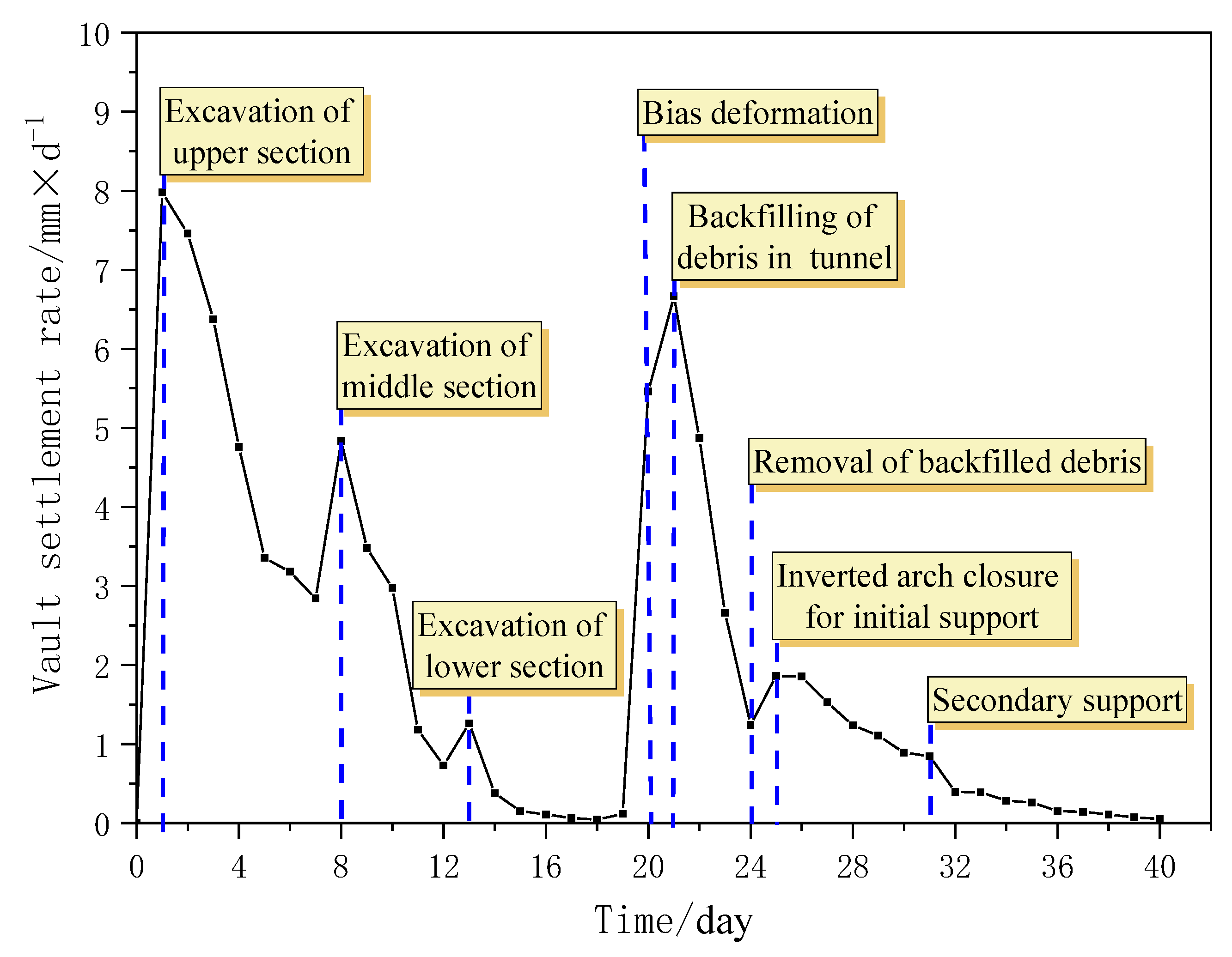
Based on numerical simulation results, various optimization measures were adopted on site, including bench excavation, crushed-stone backfilling for compression resistance, advanced grouting reinforcement, and grouting. The on site monitoring results indicate that after the bench excavation, the surrounding convergence and vault settlement values increased sharply, with a sudden change in rate. After implementing the optimized reinforcement measures, the deformation rate decreased, and unsymmetrical deformation accounted for 40.12% and 38.63% of the final convergence values. This validates the effectiveness of the unsymmetrical control method proposed in this study.

Author Contributions

Y.L.: Supervision. K.L.: Conceptualization, Software. X.L.: Writing—Original Draft. Z.Y.: Writing—review and editing. All authors have read and agreed to the published version of the manuscript.

Funding

The authors acknowledge the financial support from the National Natural Science Foundation Project of China under Grant No. 52274106 and No. 51974360, and National Key R&D Program of China under Grant No. 2022YFC3002903 for carrying out this research work.

Data Availability Statement

All data, models, or codes that support the findings of this study are available from the corresponding author upon reasonable request.

Conflicts of Interest

The authors declare no conflicts of interest. The funders had no role in the design of the study; in the collection, analyses, or interpretation of data; in the writing of the manuscript; or in the decision to publish the results.

References

  1. Wen, Y.B.; Huang, F.; Gao, X.Y. Analysis of surrounding rock stability in large-section, small-clearance, terrain-biased tunnels. Railw. Constr. 2017, 07, 77–80. [Google Scholar]
  2. Zhu, D.W. Study on Spatiotemporal Effects and Optimal Support Timing in Excavation of Terrain-Biased Soft Rock Tunnels; Chongqing University: Chongqing, China, 2012. [Google Scholar]
  3. Mu, M.C.; Huang, Z.Y. New construction technologies for shallowly buried tunnels in mixed rock strata. West. Transp. Technol. 2024, 1, 177–179. [Google Scholar]
  4. Wang, S.H.; Mei, Y.C.; Liu, Q.W. Research and application of active support mechanisms in shallowly buried large-span rock tunnels. China Railw. Sci. 2024, 45, 131–141. [Google Scholar]
  5. Chen, X. Construction mechanics characteristics and support optimization design of super large-section shallowly buried tunnels in red bed areas. Transp. World 2024, 1, 238–240. [Google Scholar]
  6. Sui, J.Y. Study on the mechanical characteristics of shallow buried tunnel excavation method in large-section loess strata. Eng. Mach. Maint. 2024, 1, 114–116. [Google Scholar]
  7. Cai, Y.C.; Wang, Q.; Zhang, Q. Analysis of slope stability in shallowly buried terrain-biased tunnels. J. Hebei Eng. Univ. 2022, 39, 56–64. [Google Scholar]
  8. Zhang, Z.L.; Liu, Y.J.; Guo, N.R. Analysis of surrounding rock deformation in large-span shallowly buried terrain-biased tunnels. Radio Eng. 2019, 3, 241–246. [Google Scholar]
  9. Wang, F. Analysis of portal landslide stability and its treatment methods in shallowly buried terrain-biased tunnels. Anhui Archit. 2019, 26, 107–113. [Google Scholar]
  10. Zhang, D.H. Construction technology for high-speed railway tunnels in shallowly buried, Terrain-Biased. Weak Surrounding Rock. Heilongjiang Transp. Sci. Technol. 2017, 40, 122–123+126. [Google Scholar]
  11. Hu, Z.; Shen, J.; Wang, Y.; Guo, T.; Liu, Z.; Gao, X. Cracking characteristics and mechanism of entrance section in asymmetrically-load tunnel with bedded rock mass: A case study of a highway tunnel in southwest China. Eng Fail Anal 2021, 122, 105221. [Google Scholar] [CrossRef]
  12. Hashash, Y.M.; Hook, J.J.; Schmidt, B.; John, I.; Yao, C. Seismic design and analysis of underground structures. Tunn. Undergr. Space Technol. 2001, 16, 247–293. [Google Scholar] [CrossRef]
  13. Xu, Q.W.; Cheng, P.P.; Su, P.S. Research on the mechanical characteristics of tunnel entrance construction in shallowly buried terrain-biased tunnels. J. Undergr. Space Eng. 2017, 13, 1311–1318+1380. [Google Scholar]
  14. Liang, Y.R. Research on the construction mechanical characteristics and control techniques of the entrance section of shallowly buried terrain-biased tunnels. China Highw. 2017, 17, 110–111. [Google Scholar]
  15. Li, Y.B. Construction technology for shallowly buried terrain-biased cut-and-cover tunnels in highway tunnel engineering. Eng. Technol. Res. 2021, 6, 96–97. [Google Scholar]
  16. Zhou, C.; Jin, W.; Ma, B. Research on drilling and blasting design and support system at the entrance of shallowly buried terrain-biased tunnels. Shanxi Archit. 2024, 50, 158–161. [Google Scholar]
  17. Daraei, A.; Sherwani, A.F.H.; Faraj, R.H.; Kalhor, Q.; Zare, S.; Mahmoodzadeh, A. Optimization of the outlet portal of Heybat Sultan twin tunnels based on the value engineering methodology. SN Appl. Sci. 2019, 1, 270. [Google Scholar] [CrossRef]
  18. Can, A.; Baskose, Y.; Gokceoglu, C. Stability assessments of a triple-tunnel portal with numerical analysis (south of Turkey). Geotech. Res. 2022, 9, 116–128. [Google Scholar] [CrossRef]
  19. Daraei, A.; Zare, S. A new multi-graph approach for selecting the sequential excavation method of civil tunnels. Tunn. Undergr. Space Technol. 2019, 91, 102999. [Google Scholar] [CrossRef]
  20. Lv, G.R.; Sui, B.; Wang, Y.J. Numerical simulation and stability analysis of excavation in shallowly buried terrain-biased tunnels. J. Shandong Univ. 2013, 43, 68–73. [Google Scholar]
  21. Li, W.J. Study on the Stability of Shallowly Buried Terrain-Biased Tunnels in Weak Surrounding Rock; Dalian University of Transportation: Liaoning, China, 2013. [Google Scholar]
  22. Liu, C.; Yang, H.; Jiang, X.; Shi, H. Shaking table test and numerical simulation for acceleration response laws of shallow-buried biased double-arch tunnel. J. Vibroeng. 2019, 21, 1188–1200. [Google Scholar] [CrossRef]
  23. Zhang, L.M.; Chao, W.W.; Liu, Z.Y.; Cong, Y.; Wang, Z.Q. Crack propagation characteristics during progressive failure of circular tunnels and the early warning thereof based on multi-sensor data fusion. Geomech. Geophys. Geo-Energy Geo-Resour. 2022, 8, 172. [Google Scholar] [CrossRef]
  24. Zhang, L.M.; Zhang, D.; Wang, Z.Q.; Cong, Y.; Wang, X.S. Constructing a three-dimensional creep model for rocks and soils based on memory-dependent derivatives: A theoretical and experimental study. Comput. Geotech. 2023, 159, 105366. [Google Scholar] [CrossRef]
  25. Bi, Z.G.; Li, X.Z.; Wang, K. Study on the disturbance space effect of construction in shallowly buried terrain-biased tunnels with small clearance. J. Henan Univ. Urban Constr. 2023, 32, 1–8. [Google Scholar]
  26. Qiu, F.Y.; Qin, L.; Li, G.D. Analysis of surrounding rock stress characteristics in shallowly buried karst tunnels with terrain bias. North. Transp. 2024, 2, 52–55. [Google Scholar]
  27. Xiao, J.Z.; Dai, F.C.; Wei, Y.Q.; Min, H.; Xu, C.; Tu, X.B.; Wang, M.L. Cracking mechanism of secondary lining for a shallow and asymmetrically-loaded tunnel in loose deposits. Tunn. Undergr. Space Technol. 2014, 43, 232–240. [Google Scholar] [CrossRef]
  28. Ma, H.L. Study on the influence of construction methods on shallowly buried, terrain-biased, Small Clearance Tunnels. Sci. Technol. Innov. 2023, 2, 149–154. [Google Scholar]
  29. Mao, Z.; An, N.; Li, R.; Xu, L.; Wu, H. Analysis of treatment effects on shallowly buried bias slope sections of tunnels based on fuzzy comprehensive evaluation. Geotech Geol Eng. 2020, 38, 4463–4477. [Google Scholar] [CrossRef]
  30. Miao, Q.C.; Nuo, C.; Zheng, W.F. Mechanism and remediation measures for large deformation of the entrance section of shallowly buried terrain-biased tunnels in fine sandstone mudstone. Hydropower Energy Sci. 2023, 41, 133–137. [Google Scholar]
  31. Xue, F.; Zhang, M. Stability of the excavation face on a shield tunnel crossing beneath an existing tunnel. Geotech Res. 2020, 7, 96–102. [Google Scholar] [CrossRef]
  32. Wang, Q.; Li, Q.; Zhu, J.; Zhu, Z. Stability of the excavation surface of a submarine shield tunnel considering the fluid-solid coupling effect and the equivalent layer. J. Mar. Sci. Eng. 2023, 11, 1667. [Google Scholar] [CrossRef]
  33. Zamora, H.Y.; Durand, F.A.; Pacheco, D.A. Three-dimensional analysis of excavation face stability of shallow tunnels. Tunn. Undergr. Space Technol. 2019, 92, 103062. [Google Scholar] [CrossRef]
  34. Dai, X.Y.; Wang, G.B.; Ye, M.; Zhang, Y.Q. Safety evaluation of crossing tunnel engineering: A case study. Appl. Sci. 2023, 13, 9459. [Google Scholar] [CrossRef]
  35. Guan, C.; Peng, H.; Wang, B. Study on stability of excavation surface of shield tunnel in clay layer. Transp. Res. Rec. J. Transp. Res. Board 2023, 2677, 675–693. [Google Scholar] [CrossRef]
  36. Zhang, Z.Q.; Chen, F.F.; Li, N.; He, M.C. Influence of fault on the surrounding rock stability for a mining tunnel: Distance and tectonic stress. Adv. Civ. Eng. 2017, 61, 2054938. [Google Scholar] [CrossRef]
  37. Xu, J.M.; Zheng, L.R.; Song, G.Y.; Zhang, D.W.; Sheil, B.; Marshall, A.M. Effects of embedded walls on tunnelling-induced sandy ground displacements: A numerical investigation. Geotechnique 2024, 1–14. [Google Scholar] [CrossRef]
  38. Xu, J.M.; Gui, J.S.; Sheil, B. A numerical investigation of the role of basements on tunnel-frame interaction in sandy soil. Comput Geotech. 2024, 169, 106197. [Google Scholar] [CrossRef]
  39. Gao, W.X.; Sun, W.L.; Zhou, W.X. Numerical simulation and monitoring analysis of excavation for shallowly buried terrain-biased tunnels. Constr. Tech. 2011, 40, 48–50. [Google Scholar]
  40. Mehrabi, R.; Baziar, M.H.; Nabizadeh, A.; Hung, W.Y. Discrete-element modelling of underground tunnel response to reverse fault rupture in sand. Proc. Inst. Civ. Eng.-Geotech. Eng. 2023, 176, 356–368. [Google Scholar] [CrossRef]
  41. Kielbassa, S.; Duddeck, H. Stress-strain fields at the tunnelling face-Three-dimensional analysis for two-dimensional technical approach. Rock Mech. Rock Eng. 1991, 24, 115–132. [Google Scholar] [CrossRef]
  42. Sterpi, D. An analysis of geotechnical problems involving strain softening effects. Int. J. Numer. Anal. Methods Geomech. 1999, 23, 142–145. [Google Scholar] [CrossRef]
  43. Chu, B.L.; Hsu, S.C.; Chang, Y.L.; Lin, S.Y. Mechanical behavior of a twin-tunnel in multi-layered formation. Tunn. Undergr. Space Technol. 2007, 22, 351–362. [Google Scholar] [CrossRef]
  44. Gao, G.; Meguid, M.A. On the role of joint roughness on the micromechanics of rock fracturing process: A numerical study. Acta Geotech. 2021, 17, 2799–2824. [Google Scholar] [CrossRef]
Figure 1. Longitudinal geological profile.
Buildings 14 01825 g001
Figure 2. Tunnel cross-section.
Buildings 14 01825 g002
Figure 3. Tunnel surrounding rock deformation diagram.
Buildings 14 01825 g003
Figure 4. The deformation of the tunnel section: (a) deformation for temporary inverted arch before the excavation of the lower bench; (b) the crack of secondary lining.
Buildings 14 01825 g004
Figure 5. The ground surface deformation: (a) surface crack; (b) holes.
Buildings 14 01825 g005
Figure 6. Numerical model: (a) rock body region division; (b) comparison between simulated results and actual engineering conditions on the ground surface.
Buildings 14 01825 g006
Figure 7. Different excavation methods: (a) full-section excavation; (b) bench excavation—upward; (c) bench excavation—downward.
Buildings 14 01825 g007
Figure 8. Different support treatment methods: (a) lining support treatment; (b) slope reduction treatment.
Buildings 14 01825 g008
Figure 9. Distribution of measurement points in tunnel’s surrounding rock.
Buildings 14 01825 g009
Figure 10. Distribution characteristics of displacement field during tunnel excavation and unloading of surrounding rock.
Buildings 14 01825 g010
Figure 11. Distribution characteristics of Y-direction displacement field during tunnel excavation and unloading of surrounding rock.
Buildings 14 01825 g011
Figure 12. Distribution characteristics of X-direction displacement field during tunnel excavation unloading and surrounding rock deformation process.
Buildings 14 01825 g012
Figure 13. (a) Portal section of advanced support; (b) grouting schematic diagram.
Buildings 14 01825 g013
Figure 14. Grouting mortar at the top ground of tunnel.
Buildings 14 01825 g014
Figure 15. Peripheral convergence time–history curve.
Buildings 14 01825 g015
Figure 16. Peripheral convergence rate–time profile.
Buildings 14 01825 g016
Figure 17. The emergency control measures: (a) backfill of debris in the tunnel; (b) spillway pipe at left arch of tunnel; (c) grouting at ground surface.
Buildings 14 01825 g017
Figure 18. Vault settlement time–history curve.
Buildings 14 01825 g018
Figure 19. Time–course plot of the rate of settlement of the vault.
Buildings 14 01825 g019
Table 1. Geotechnical properties.
Epoch CauseGeotechnical Designationφ (°)c (kPa)Comprehensive Coefficient of Internal FrictionCompression Modulus Es
(MPa)
Saturated Compressive Strength (Mpa)Basic Bearing Capacity σ0
(kPa)
Grade of Geotechnical Engineering
Q4mlHand fill I
Q4al + plSilty clay350.30.312 180III
J2 + 3gjdDacite porphyry35450.315 250III
J2 + 3gjdDacite porphyry45 0.5 500IV
J2 + 3gjdDacite porphyry55 0.6 800V
γy3Granite35450.315 250III
γy3Granite45 0.5 500IV
γy3Granite55 0.6 30.7800V
Table 2. Microscopic parameters of rock PBM.
R m a x R m i n ρ E C k n / k s E ¯ c k ¯ n / k ¯ S ϕ ¯ σ ¯ c τ ¯ C
m m m m k g / m 3 G P a G P a ° M P a M P a
0.450.327002.11.52.11.5451.23.2
Table 3. Vertical stress values at monitoring points before and after excavation/MPa.
Pre-ExcavationFull-Section ExcavationStepwise ExcavationLining Support TreatmentSlope Reduction Treatment
10.2930.0410.0420.2950.374
20.6990.1480.1480.3370.144
30.4680.8750.8730.3940.781
40.5210.9310.9280.4280.784
50.3510.340.340.3730.307
60.3440.3830.3830.4180.31
70.5850.8490.8460.7370.706
80.6060.7830.7810.7610.735
Table 4. Horizontal stress values at monitoring points before and after excavation/MPa.
Pre-ExcavationFull-Section ExcavationStepwise ExcavationLining Support TreatmentSlope Reduction Treatment
10.220.3450.3460.2030.341
20.3480.3260.3270.3540.326
30.2830.150.1490.3880.129
40.3390.1910.190.4580.173
50.2750.2550.2560.1950.278
60.2510.2920.2920.1860.24
70.3140.420.4210.3380.374
80.3230.3270.3280.3080.336
Disclaimer/Publisher’s Note: The statements, opinions and data contained in all publications are solely those of the individual author(s) and contributor(s) and not of MDPI and/or the editor(s). MDPI and/or the editor(s) disclaim responsibility for any injury to people or property resulting from any ideas, methods, instructions or products referred to in the content.

