Abstract
This study examines the effects of iron ore tailing (IOT) replacement ratios and the hybridization of steel fiber (SF) and polyethylene (PE) fiber (PF) on the mechanical, sulfate freeze–thaw (F–T) resistance, and microscopic characteristics of IOT concrete. The mechanical properties of specimens including compressive strength (fcu) and splitting tensile strength (fsts) were evaluated. Sulfate F–T cycle indices of specimens including surface damage, fcu loss, relative dynamic elastic modulus (RDEM), and mass loss are examined. Meanwhile, microscopic characteristics are analyzed using industrial computer technology (CT) and scanning electron microscopy (SEM). Results indicated that IOT replacement ratios below 40% positively influenced mechanical properties and sulfate F–T resistance, whereas ratios exceeding 40% exhibited adverse effects. Incorporating hybrid SF and PF further enhanced the mechanical properties and sulfate F–T resistance of IOT concrete. The IOT concrete containing 1.5% SF and 0.6% PF (designated T40S1.5P0.6) demonstrates significantly improved mechanical properties and sulfate F–T resistance. A set of parameters was proposed to predict the fsts. The Weibull damage model, capable of quantitatively reflecting the F–T damage of IOT concrete, was established. The pore structure of IOT concrete gradually deteriorates with increasing sulfate F–T cycles. The pore characteristics of T40S1.5P0.6 were superior. This was further validated through SEM observations.
1. Introduction
In recent years, steel demand has surged due to global industrialization, leading to a significant increase in iron ore tailings (IOTs) [1]. Many countries worldwide face challenges due to the overcapacity of IOTs [2,3]. In 2018, China produced 475 million tons of IOTs [4]. Currently, IOTs are typically managed through open-pit stacking and landfilling, processes that consume significant land area and degrade soil quality, thereby posing severe environmental challenges [5,6,7]. Hence, IOT recovery and utilization are indispensable for energy preservation, safeguarding the environment, and ensuring the sustainable evolution of the mining field [8,9].
IOTs are frequently utilized in concrete production as partial or complete substitutes for river sand (RS) [10,11,12]. This approach helps decrease the excessive use of RS and conserves landfill space [13].
Consequently, research conducted by scholars, including Ismail et al. [14] and Shettima et al. [4], has revealed that IOT concrete shows superior mechanical properties, notably in compressive strength (fcu) and flexural strength (ff). These properties are notably superior to those of ordinary concrete. Similarly, Zhang et al. [15] determined that the optimal replacement ratio of IOTs is between 20% and 40%. Xu et al. [16,17] and Li et al. [18] observed that integrating 30–40% IOTs was found to significantly improve the performance of recycled aggregate concrete (RAC). Tian et al. [10] found that the incorporation of IOTs to replace 35% of natural aggregate (NA) resulted in concrete specimens showing maximum carbonation resistance, impermeability, and freeze–thaw (F–T) resistance. Xlab et al. [19] observed that IOT concrete exhibits superior durability compared to ordinary concrete. Previous studies suggest significant potential in utilizing IOTs for environmentally friendly concrete production in construction, and the produced IOT concrete offers certain performance advantages. However, this alone may not be sufficient to enhance concrete toughness, limiting the widespread adoption of IOT concrete.
Fiber, as a concrete performance-enhancing material, can inhibit concrete crack propagation [20], thereby enhancing concrete toughness, strength, and durability [21,22,23,24,25]. Huang et al. [26,27,28] utilized IOTs instead of silicon sand to create green-engineered cementitious composite (ECC) materials, thus reducing material costs while maintaining the mechanical properties of traditional ECCs. Zhu et al. [29] scrutinized ultra-high-performance concrete (UHPC) containing industrial waste materials and established that the strength of UHPC decreases with a full replacement of IOTs. Bao et al. [30] discovered that the IOT cement-based composite, reinforced with polyvinyl alcohol (PVA) fiber, exhibits multiple cracking and high ductility. Furthermore, other researchers have discovered that fibers of varying types, sizes, and elastic moduli have distinct effects on concrete performance; incorporating two or more fiber types enhances their benefits compared to using a single type [31,32]. Kb et al. [33] discovered that concrete incorporating hybrid steel fiber (SF) and basalt fiber (BF) alongside 30% IOTs exhibits superior performance. Afroughsabet et al. [34] discovered that concrete containing 0.85% SF and 0.15% polypropylene (PP) fibers exhibits the most comprehensive performance. Wang et al. [35] conducted a quantitative assessment of void characteristics and durability, revealing that the hybrid SF-PP composite enhances mechanical properties such as compressive strength fcu and splitting tensile strength (fsts) while decreasing total porosity post-salt F–T exposure. However, it also leads to reduced permeability.
The abovementioned research shows that incorporating fibers (single and mixed admixture) can address the brittleness of iron tailing concrete. Additionally, fibers improve their mechanical properties and durability. Therefore, it is essential to study the impact of hybrid SF and polyethylene (PE) fiber (PF) on IOT concrete. However, the existing research about IOT concrete mainly focused on fcu, ductility and elastic modulus [36,37,38,39]. Few studies have examined the resistance of hybrid SF and polyethylene (PE) fiber (PF)-reinforced IOT concrete to sulfate F–T cycle resistance. Additionally, research on the evolution of three-dimensional pore structures and the damage mechanisms in hybrid SF-PF-reinforced IOT concrete under these conditions, using industrial computer scanning techniques (CT), is also limited.
This paper focuses on investigating the fcu and fsts of hybrid SF-PF-reinforced IOT concrete. F–T cycle testing is conducted using an Na2SO4 solution to evaluate sulfate F–T cycle indices including fcu loss, mass loss, and relative dynamic elastic modulus (RDEM). A damage equation for F–T is derived. Furthermore, microscopic characteristics are analyzed using CT and scanning electron microscopy (SEM). The research findings in this paper can address the shortcomings of previous studies, providing experimental data and theoretical support for the broader application of hybrid SF-PF-reinforced IOT concrete.
2. Experimental Details
2.1. Raw Materials
2.1.1. Cementitious Material
The cementitious materials in this test comprised fly ash (FA) and ordinary Portland cement (OPC) PO 42.5R Type II. Table 1 presents the chemical compositions of OPC and FA.

Table 1.
Chemical compositions of OPC and FA.
2.1.2. Aggregates
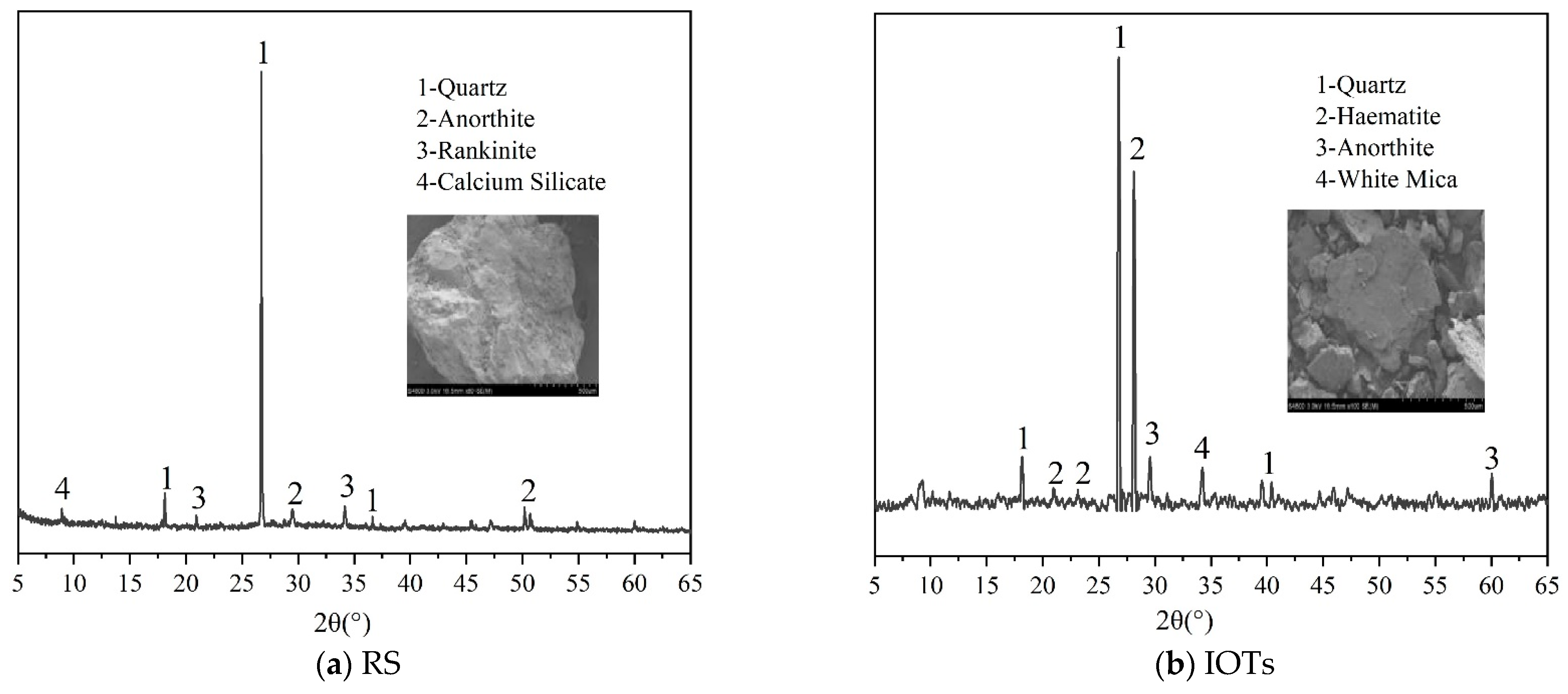
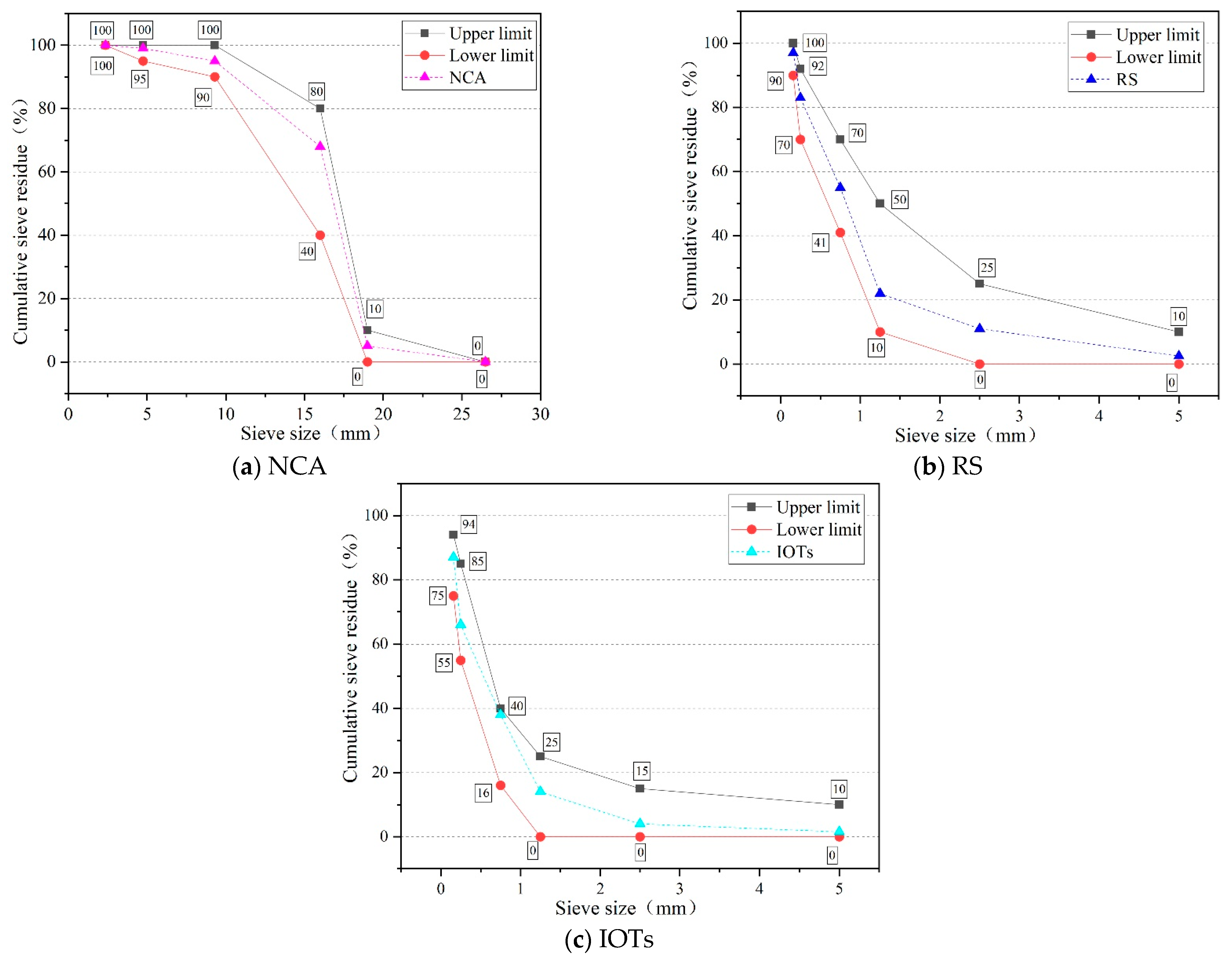
The coarse aggregate (NCA) used in this study consisted of crushed stone from Xi’an. The fine aggregate comprised Chanhe River sand (RS) and IOTs. Within Table 2, the key physical properties of both coarse and fine aggregates are detailed. Meanwhile, Figure 1 showcases the principal components and micro-morphology of RS and IOTs, as analyzed via X-ray diffraction (XRD) and scanning electron microscopy (SEM). It found that the crystal composition tested by XRD of RS and IOTs is mainly quartz, and chemical activity was steady, and the SEM results found that IOTs had more angular surfaces than that of RS. According to the Chinese national standard (GB/T14684-2011) [40], Figure 2 displays the aggregation curves of both coarse and fine aggregates. It can be observed that the sieve size of IOTs was smaller than that of RS.
Table 2.
Physical properties of aggregates.

Figure 1.
Microscopic analysis of RS and IOTs.
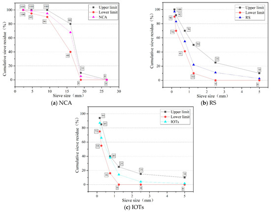
Figure 2.
Aggregate grading curve.
2.1.3. Steel Fiber and Polyethylene Fiber
In the test, SF and PF fibers were utilized, and their characteristic parameters are presented in Table 3.
Table 3.
Fiber characteristic parameters.
2.2. Mixing Proportions
In Table 4, the mixed proportions of the 10 surveyed groups are listed. The experiment was divided into two parts. In the first part, IOTs were replaced at ratios of 0–100% to investigate their impact on concrete performance. In the second part, SF and PF fibers were added at a 40% replacement ratio of IOTs. SF had a volume content of 1.5%, while PF varied at 0.2%, 0.4%, 0.6%, and 0.8% respectively. This part primarily aimed to investigate the extent to which hybrid fibers (SF and PF) could most significantly improve the performance of IOT concrete.
Table 4.
Mixing proportion (kg/m3).
Based on the Chinese standard GB/T 50081-2019 [41], this study prepared samples in a laboratory environment. After molding, the specimens were kept at a temperature of 20 °C ± 5 °C and a relative humidity greater than 50% for 2 d. After demolding, they were placed in a standard curing box at 20 °C ± 2 °C and a relative humidity of over 95% for 28 d. Cubic specimens measuring 100 mm × 100 mm × 100 mm were prepared for testing fcu and fsts, while prismatic specimens prepared measuring 100 mm × 100 mm × 400 mm were used for testing mass loss and RDEM. Three parallel specimens were employed for each test.
2.3. Experimental Program
Following GB/T50081-2019 [41] standards, fcu, and fsts were tested using a 1000 kN compression testing machine from mechanical testing and simulation (MTS), with the chuck being changed accordingly. A force control of 0.5 MPa/s was selected.
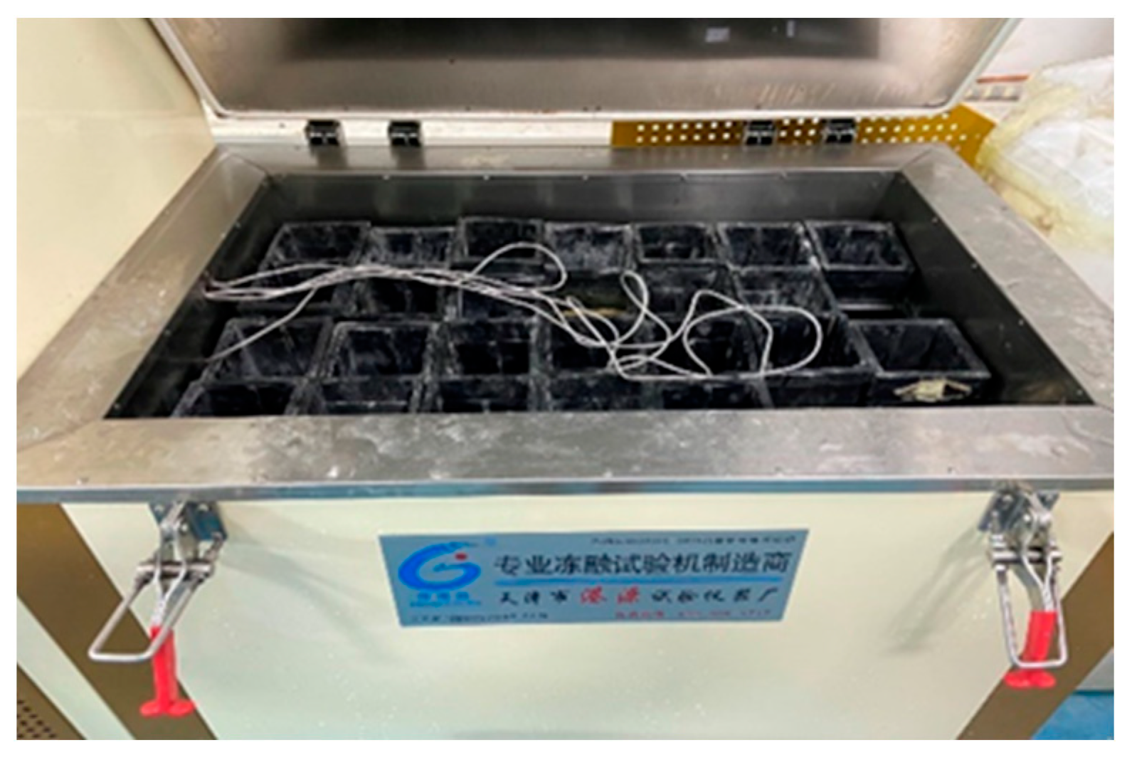
Frost resistance testing was conducted according to GB/T50082-2009 [42] standards using a rapid F–T machine with a 10% Na2SO4 solution [43,44,45], as shown in Figure 3. The 100 mm × 100 mm × 400 mm specimens were prepared for testing RDEM and mass loss using a non-metal ultrasonic analyzer and an electronic scale, respectively, after 25 F–T cycles. The 100 mm × 100 mm × 100 mm specimens were prepared for testing fcu loss using a 1000 kN MTS after 25 F–T cycles.

Figure 3.
Sulfate F–T cycle testing.
Industrial CT scanning, a non-destructive testing method, quantitatively evaluates concrete pore distribution. Specimens measuring 100 mm × 100 mm × 100 mm were scanned using an industrial CT scanner (MS-Voxe1450), as shown in Figure 4. The scanner operated at 380 kV and 1.3 mA, with a 0.5 s exposure time, performing continuous scans across the specimen’s cross-section to a depth of 0.5 mm and at 20 mm intervals along its height. AVIZO 3D image processing software was utilized for image data extraction and 3D pore distribution reconstruction.
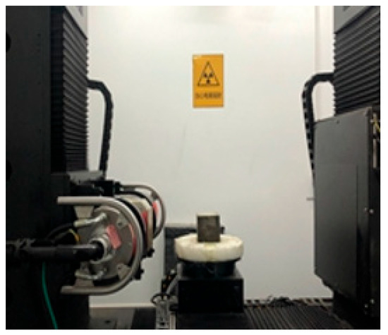
Figure 4.
CT scanning specimens.
Micro-morphology testing included sampling from 100 mm × 100 mm × 100 mm cube blocks subjected to various sulfate F–T cycles. Preceding analysis with the S-4800 cold field emission SEM, as shown in Figure 5, the samples, approximately 5 mm × 5 mm × 2 mm in size, were subjected to pretreatment involving drying at 40 °C for 24 h and gold spray coating.
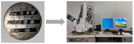
Figure 5.
SEM testing.
3. Experimental Results of Workability and Mechanical Properties
3.1. Workability
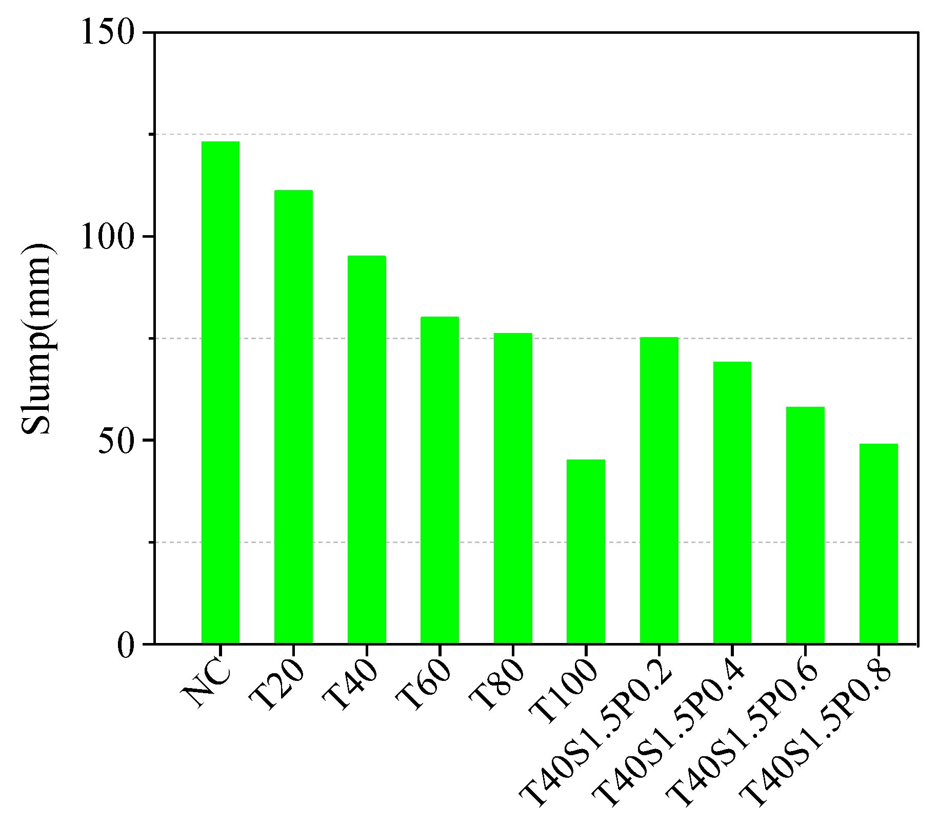
According to the Chinese standard GB/T50080-2002 [46], concrete workability is assessed by analyzing slump, as indicated in Figure 6. Slump exhibits a linear decline with increasing IOT content, particularly pronounced in T100, which experiences a 63.41% decrease compared to NC. Comparable trends have been documented in the literature [11], attributed to the larger surface area, coarser particles, finer grain size, and greater water absorption of IOTs in comparison to RS [12]. Additionally, the addition of SF and PF to concrete reduces the slump. For instance, compared to NC, slump values decreased by 39.02%, 43.9%, 52.84%, and 60.16%, respectively. This reduction is primarily attributed to fiber adhesion, tension, and water absorption [47]. Furthermore, fibers dispersed in IOT concrete easily form a network structure, impeding concrete flow [48]. From the aforementioned analysis, it can be inferred that the inclusion of IOTs or fibers in concrete results in a reduction in slump.

Figure 6.
Tested results of slump.
3.2. Compressive Strength and Splitting Tensile Strength
Figure 7 shows the fcu results. T20 and T40 experienced respective increases in fcu by 3.56% and 5.34%, in contrast to the control group (NC). However, fcu values for T60, T80, and T100 are lower than that of NC, especially T100. This trend has been observed in previous studies [4]. The observed trends can be attributed to the “Filling effect” and “Pozzolanic effect” of IOTs, particularly the latter, improving the internal structure of the matrix when the replacement ratio of IOTs is less than 40% [49,50]. However, when the replacement ratio exceeds 40%, defects in IOT concrete become more evident due to poor gradation, resulting in increased porosity and micro-cracks [17]. Upon a mixed addition of SF and PF to IOT concrete, fcu initially increases and then decreases with increasing PF content. For instance, compared to NC, fcu values with PF volume content of 0.2%, 0.4%, 0.6%, and 0.8% increased by 18.3%, 19.23%, 22.35%, and 19.54%, respectively. This enhancement is primarily attributed to the dispersed fibers inhibiting concrete crack development. With an increase in the amount of calcium silicate hydrate (C-S-H) gel inside the concrete, the bonding stress between the fibers and the matrix increases, leading to a significant enhancement in fcu [51,52,53,54]. However, when the total volume content of hybrid SF and PF exceeds a threshold, fiber agglomeration occurs, resulting in the formation of a weak interface. This phenomenon has been confirmed by SEM in Section 5.2.
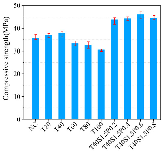
Figure 7.
Tested results of fcu.
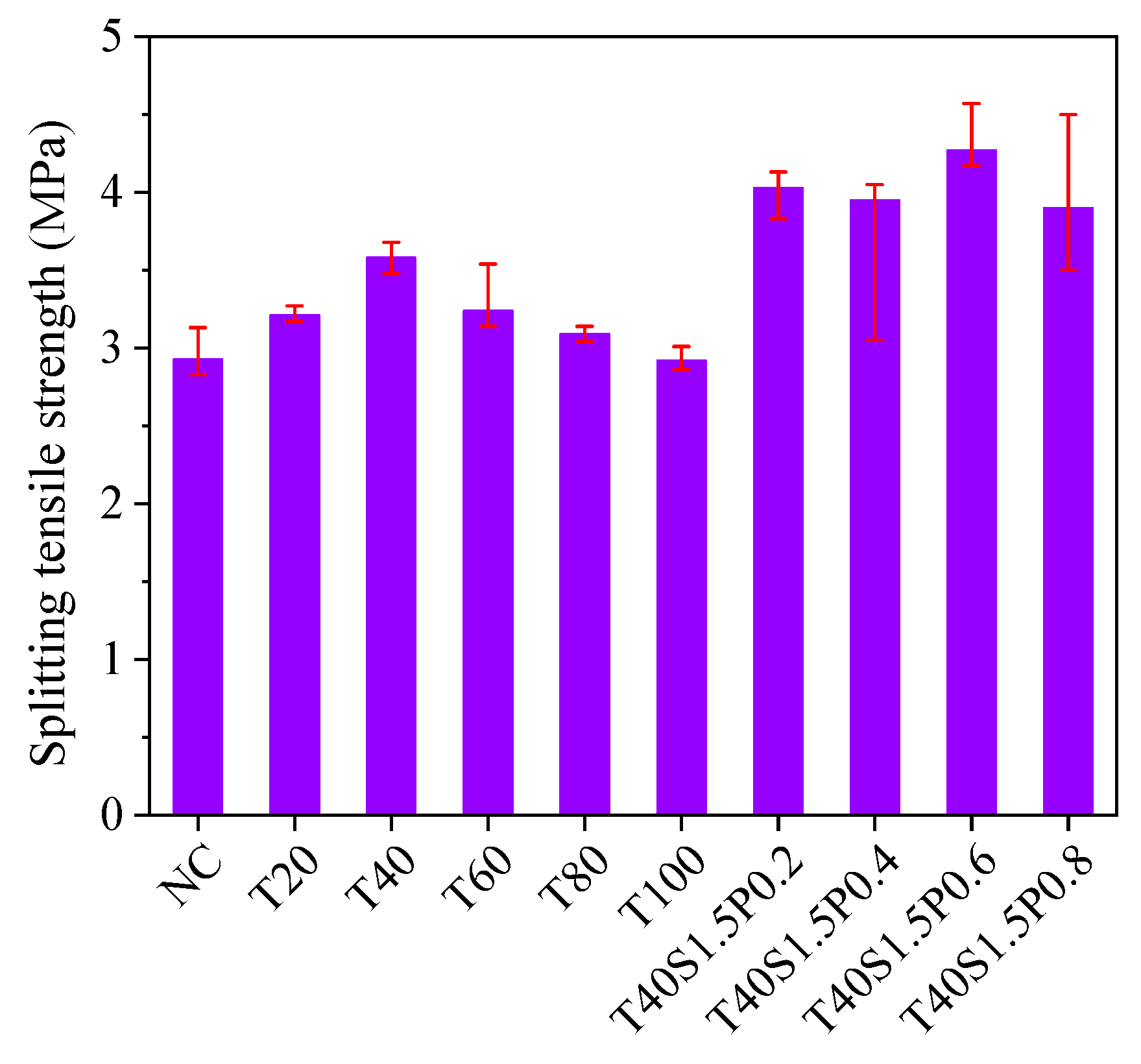
Figure 8 shows the fsts results. Generally, fsts exhibit a trend similar to that of fcu. T20, T40, T60, T80, and T100 exhibited increases in fsts by 8.72%, 18.16%, 9.56%, 5.19%, and 0.34%, respectively, relative to NC. These findings are consistent with previous studies [55]. Additionally, IOTs with a 40% replacement ratio exhibit the most pronounced strengthening effect on IOT concrete, consistent with previous research [56]. Following the mixed addition of SF and PF, the fiber bridging effect results in higher fsts compared to NC, indicating a positive impact of fibers on fsts [57,58,59]. For instance, compared to NC, fsts increased by 27.29%, 25.82%, 31.38%, and 24.87%, respectively. The discussion above highlights that fibers have a more pronounced strengthening effect on fsts than on fcu.
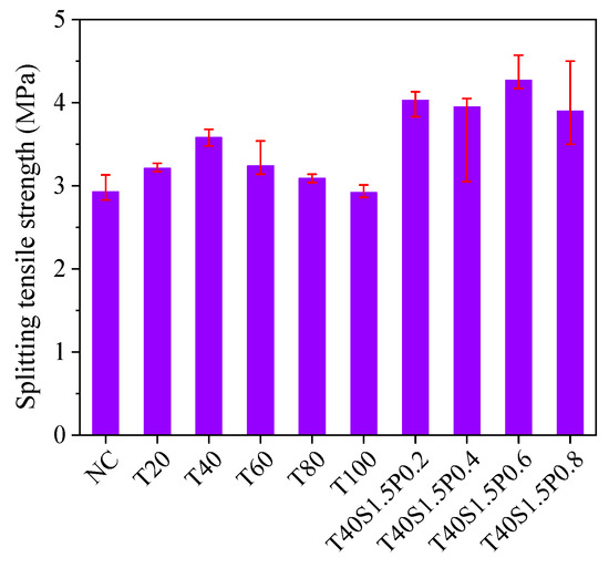
Figure 8.
Tested results of fsts.
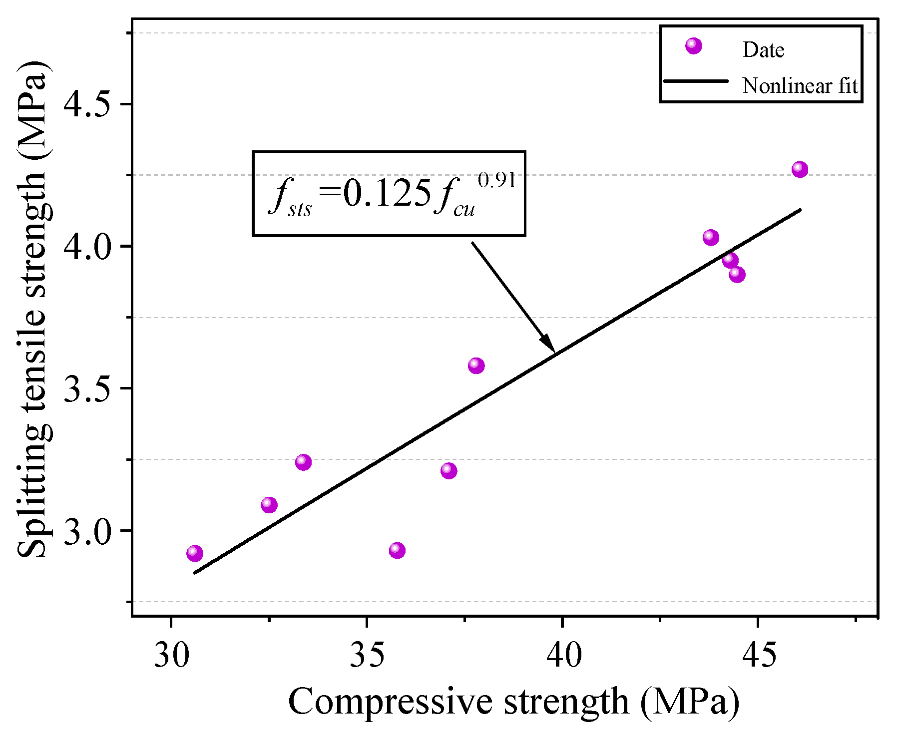
Equation (1) describes the association between fcu and fsts, which is well established. Parameters a and b vary across different versions and are proposed based on numerous Chinese and foreign national standards and studies, including ACI318-11 (a = 0.5, b = 0.5), ACI363R (a = 0.52, b = 0.5), and EC4-04 (a = 0.3, b = 0.67) [60,61]. Parameters a and b are determined through the fitting, resulting in a = 0.125 and b = 0.91, as illustrated in Figure 6 and described by Equation (2). Finally, this paper compares the test results with the calculation results of national standards, as depicted in Figure 9.
where a and b are constants.
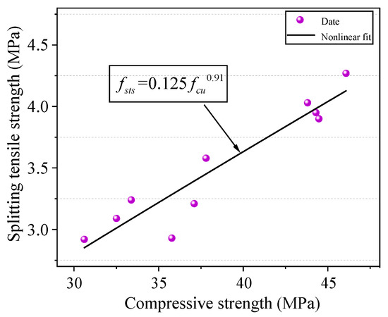
Figure 9.
Relationship between fcu and fsts.
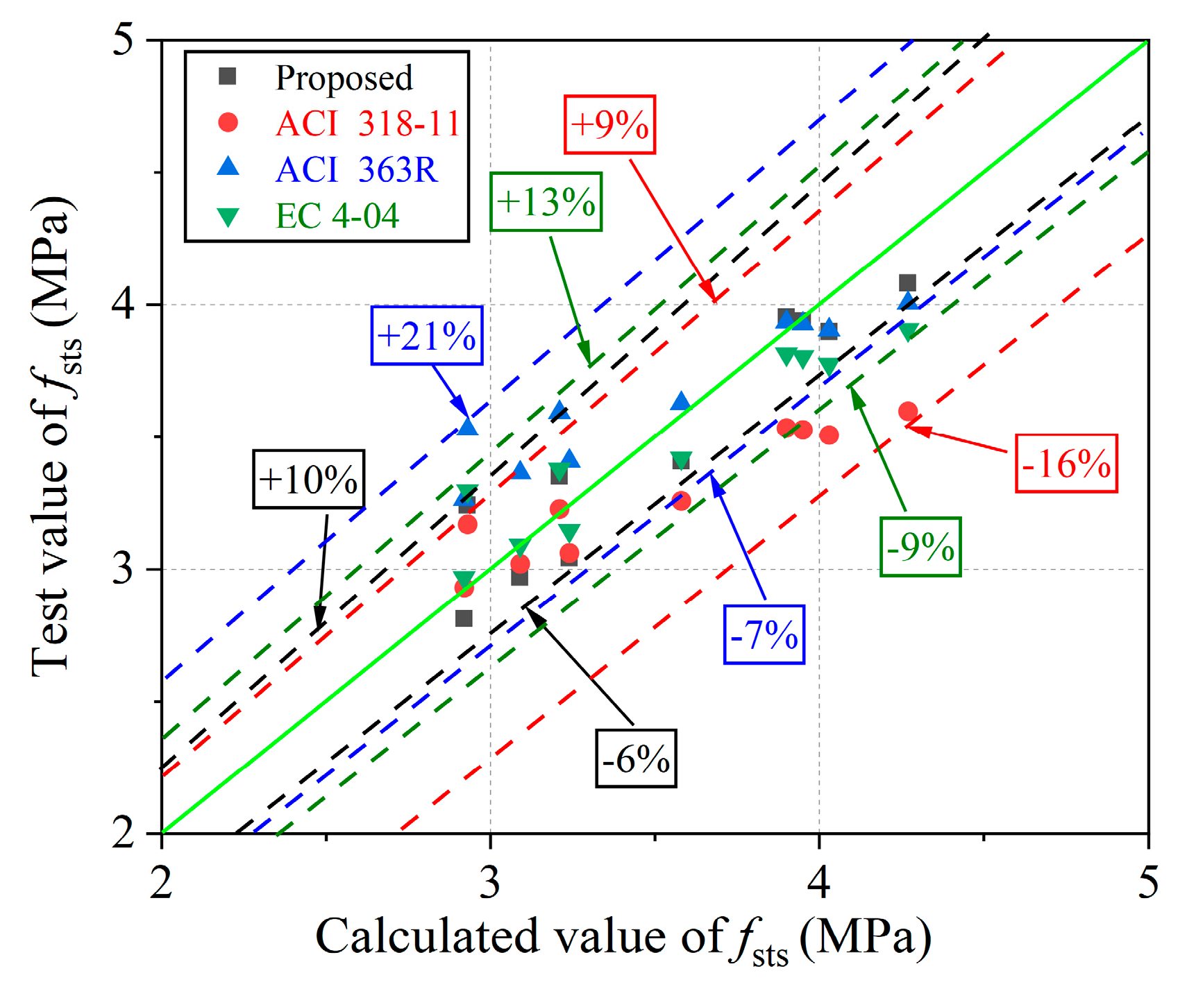
In Figure 10, the errors between the calculated results from the three aforementioned standards and the test results range from −16% to 9%, 21% to −7%, and −9% to −17%, respectively. The results derived from these standards exhibit significant disparities from the test results, making implementation challenging. Nevertheless, it is worth mentioning that the difference between the calculated results and test results of Equation (2) proposed in this study is relatively small, ranging from −6% to 10%.
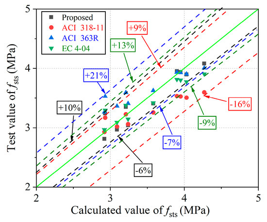
Figure 10.
Experimental and predicted values of fsts.
3.3. Toughening Mechanism of Fiber
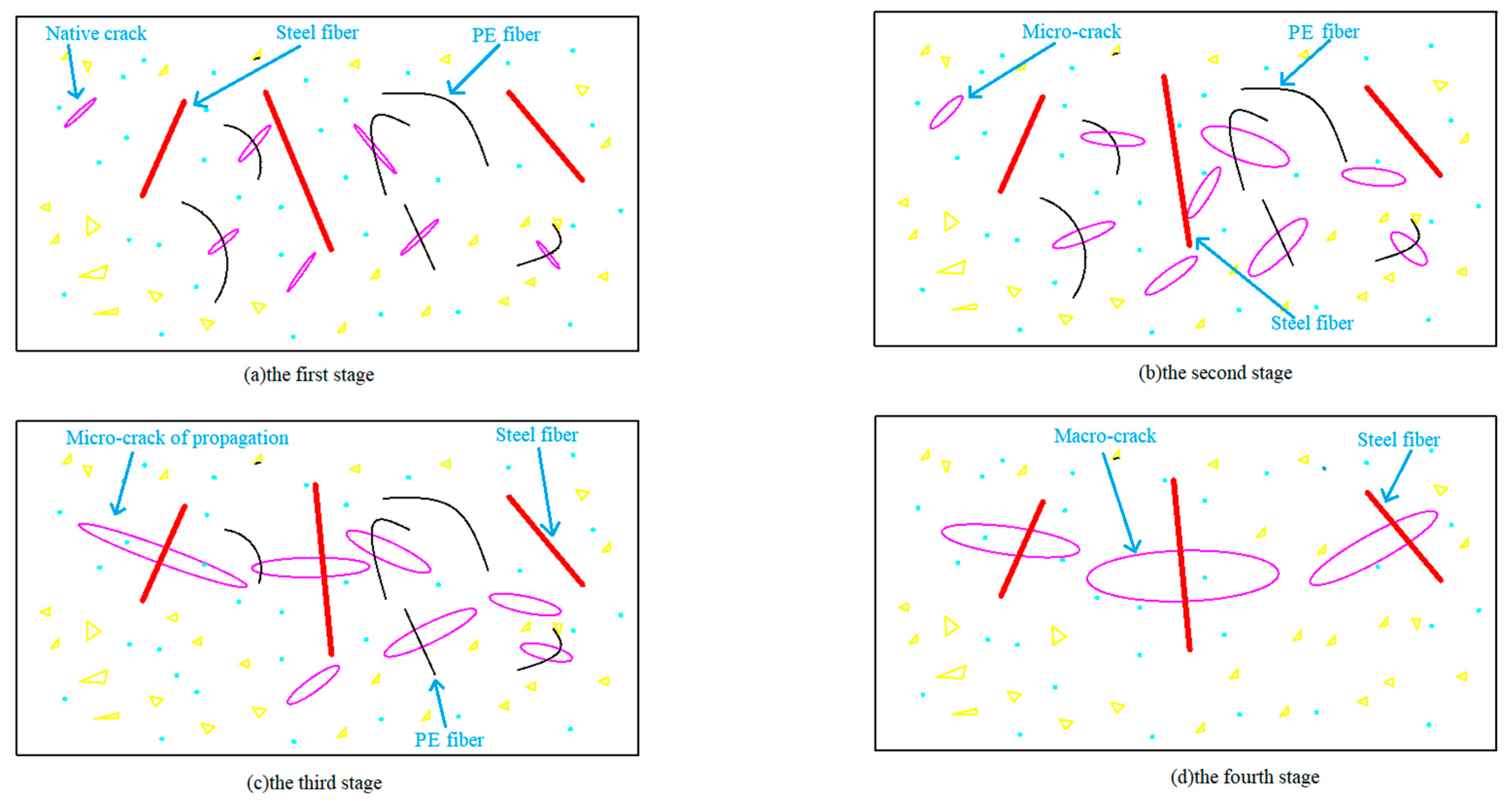
The crack propagation model of fiber-restrained concrete is depicted in Figure 11. SF, characterized by high elastic modulus, and PF, characterized by low elastic modulus, are randomly dispersed in the matrix to impede crack propagation at various scales, thereby significantly enhancing concrete ductility. Initially, under low matrix loads, PF limits primary crack development, as illustrated in Figure 11a. As the load increases, primary cracks evolve into micro-cracks within the matrix, and the PF’s bridging effect inhibits crack progression, as depicted in Figure 11b. Subsequently, as the load intensifies and micro-cracks propagate, PF bridges may disengage or fracture, transferring the load to adjacent SF and uncracked matrix regions, depicted in Figure 11c. As loading persists, micro-cracks transition to macro-cracks, with SF continuing to bridge, until, ultimately, rapid macro-crack expansion leads to SF detachment and concrete failure, shown in Figure 11d.
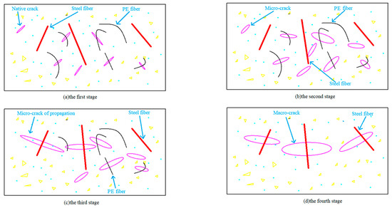
Figure 11.
Crack propagation model.
4. Experimental Results of Sulfate F–T Resistance
4.1. Surface Damage
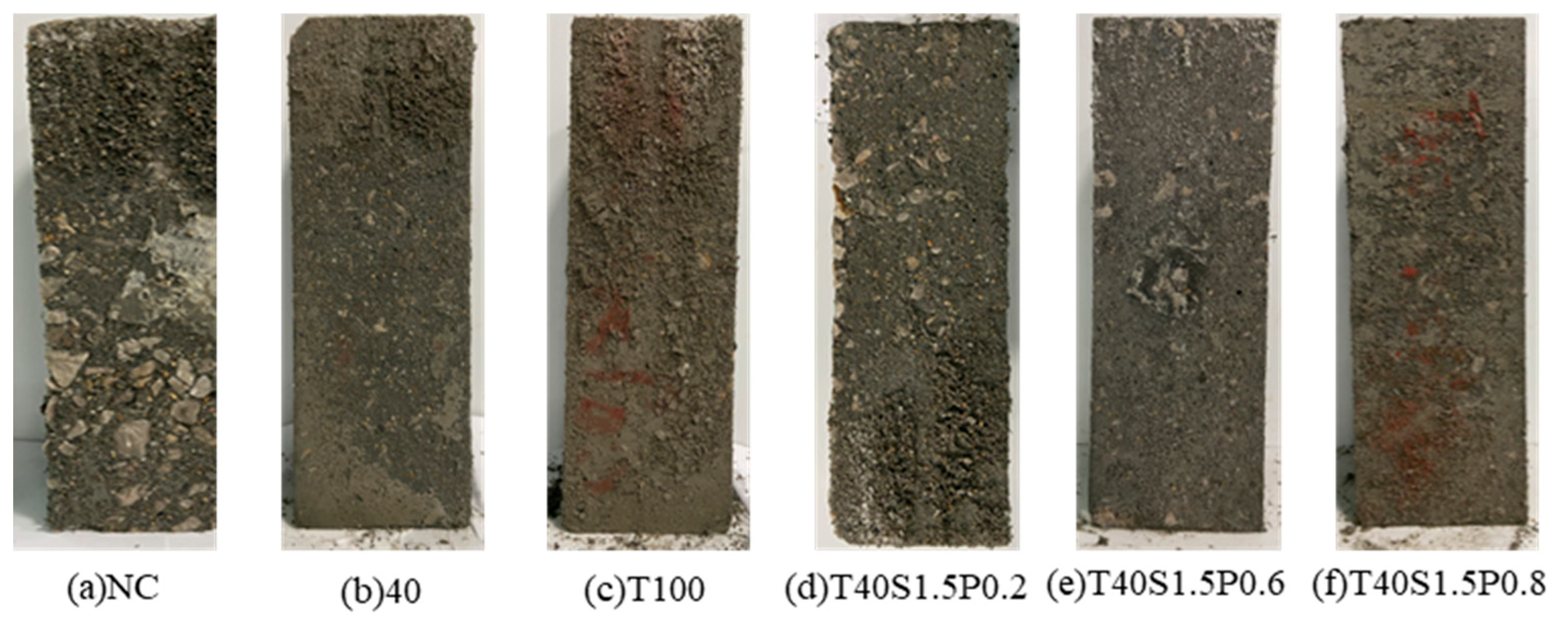
Sulfate F–T cycling is a common cause of severe deterioration in concrete engineering [62]. Surface damage for each test sample is depicted in Figure 12. The surface damage of NC is more severe, with increased exposure of NCA after 100 F–T cycles. The surfaces of T20 and T40 show mortar peeling, while damage is more pronounced on T60, T80, and T100, where NCA is visible, particularly on T100. This is primarily due to the poor distribution caused by a high substitution of RS with IOTs, accelerating the deterioration of IOT concrete. However, after the mixed addition of SF and PF, the amount of peeled-off mortar is relatively small, particularly evident in T40S1.5P0.6.
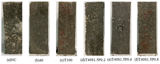
Figure 12.
Surface damage after 100 F–T cycles.
4.2. Compressive Strength Loss
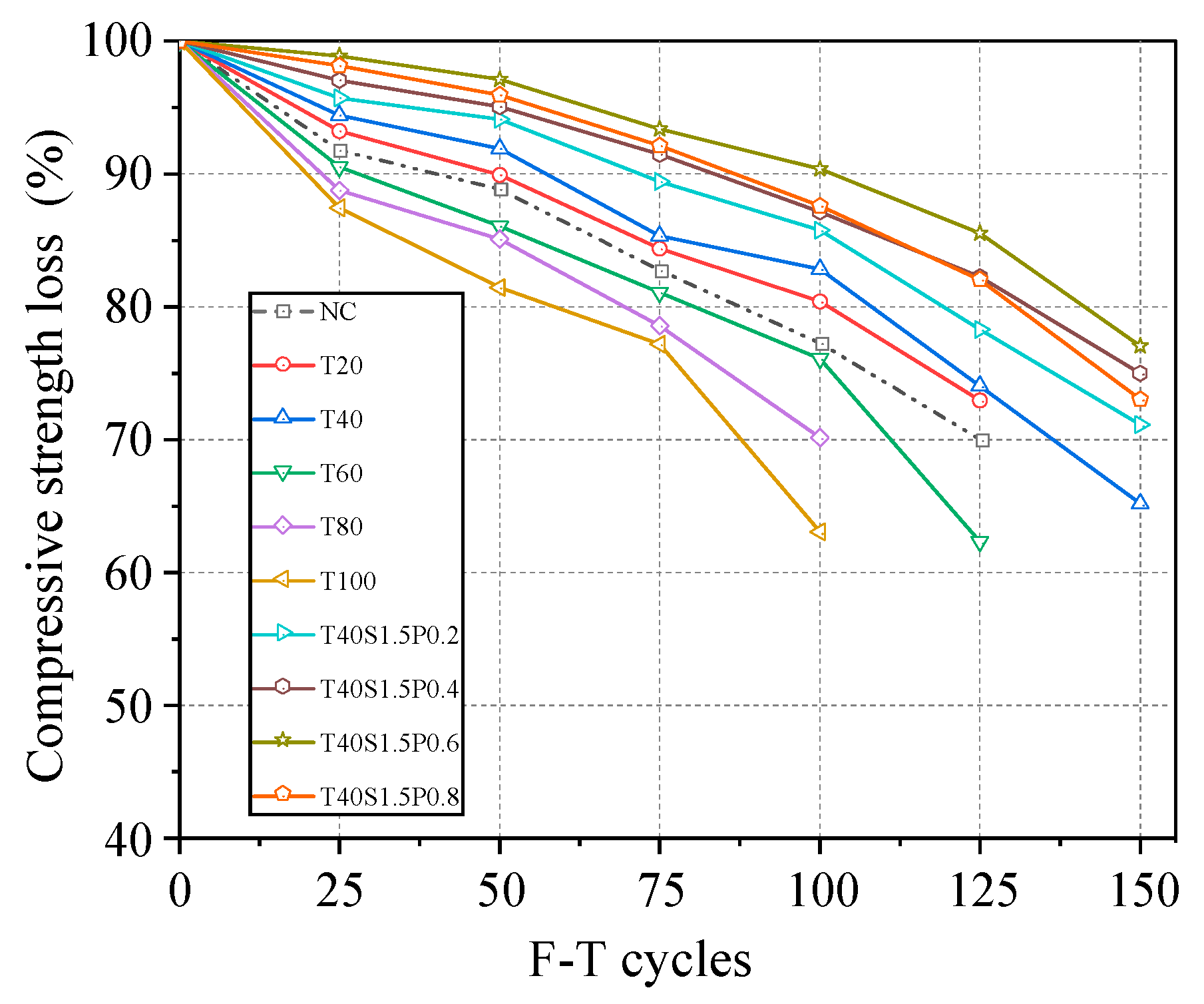
Figure 13 illustrates the fcu loss rates of concrete under various F–T cycles. These rates increase with the number of F–T cycles due to continuous F–T cycling, which promotes internal deformation and damage to the internal interfaces of concrete. The bond strength of cement mortar gradually decreases, as does that between fiber and aggregate. For instance, after 100 F–T cycles, the fcu loss rates for NC, T20, T40, T60, T80, and T100 are 22.7%, 19.6%, 17.2%, 23.9%, 29.8%, and 36.9%, respectively. Notably, the fcu loss rates of T80 and T100 exceed the 25% threshold. Following 125 F–T cycles, the fcu loss rates of T20, NC, and T60 surpass 25%, except for T40. Upon the addition of SF and PF, the fcu loss rates significantly decrease. This is attributed to an improved refinement of air voids after fiber addition, aiding in the release of expansion pressure from water freezing. However, exceeding the threshold of total volume content of hybrid SF and PF may have a negative impact due to uneven dispersion. For instance, after 150 F–T cycles, the fcu loss rates of T40S1.5-P0.4 and T40S1.5-P0.6 remain below 25%, while those of T40S1.5-P0.8 and T40S1.5-P0.2 are 27% and 28.9%, respectively.
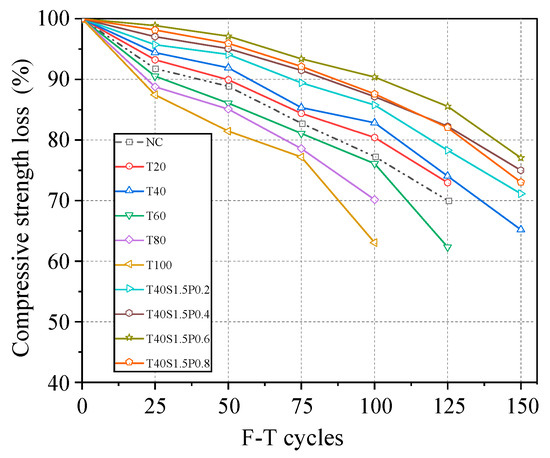
Figure 13.
fcu loss after F–T cycle.
4.3. Mass Loss
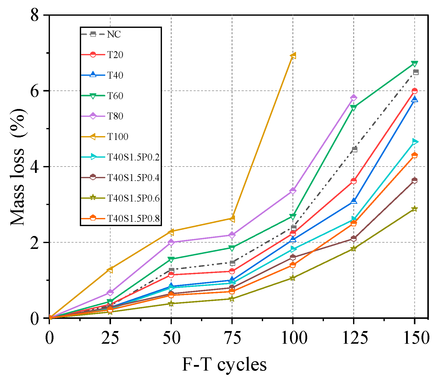
Figure 14 illustrates the mass losses of concrete under different F–T cycles. A consistent trend emerges; mass loss significantly increases after 75 F–T cycles. By 150 F–T cycles, mass loss can be roughly categorized into these three ranges: less than 3%, between 3% and 5%, and more than 5%. Mass losses for T20 and T40 are lower than those for NC, while those for T60, T80, and T100 exceed NC. Notably, the mass loss for T100 reaches 6.93% after 100 F–T cycles. It’s observed that the relatively high replacement ratio of IOTs accelerates mass loss, consistent with prior studies [16]. This is primarily due to increased internal pores and micro-cracks at high IOT replacement ratios, accelerating concrete delamination [63]. Additionally, the relatively small particle size of IOTs hinders bonding with C-S-H gel compared to RS. After the addition of SF and PF, mass loss decreases and remains below 5% after 150 F–T cycles, attributed to fiber-refining pores and reducing porosity. Unfortunately, the mass loss for T40S1.5P0.8 increases, likely due to fiber agglomeration affecting concrete performance, leading to increased delamination, as discussed in Section 3.2.
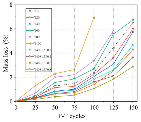
Figure 14.
Mass loss after sulfate F–T cycle.
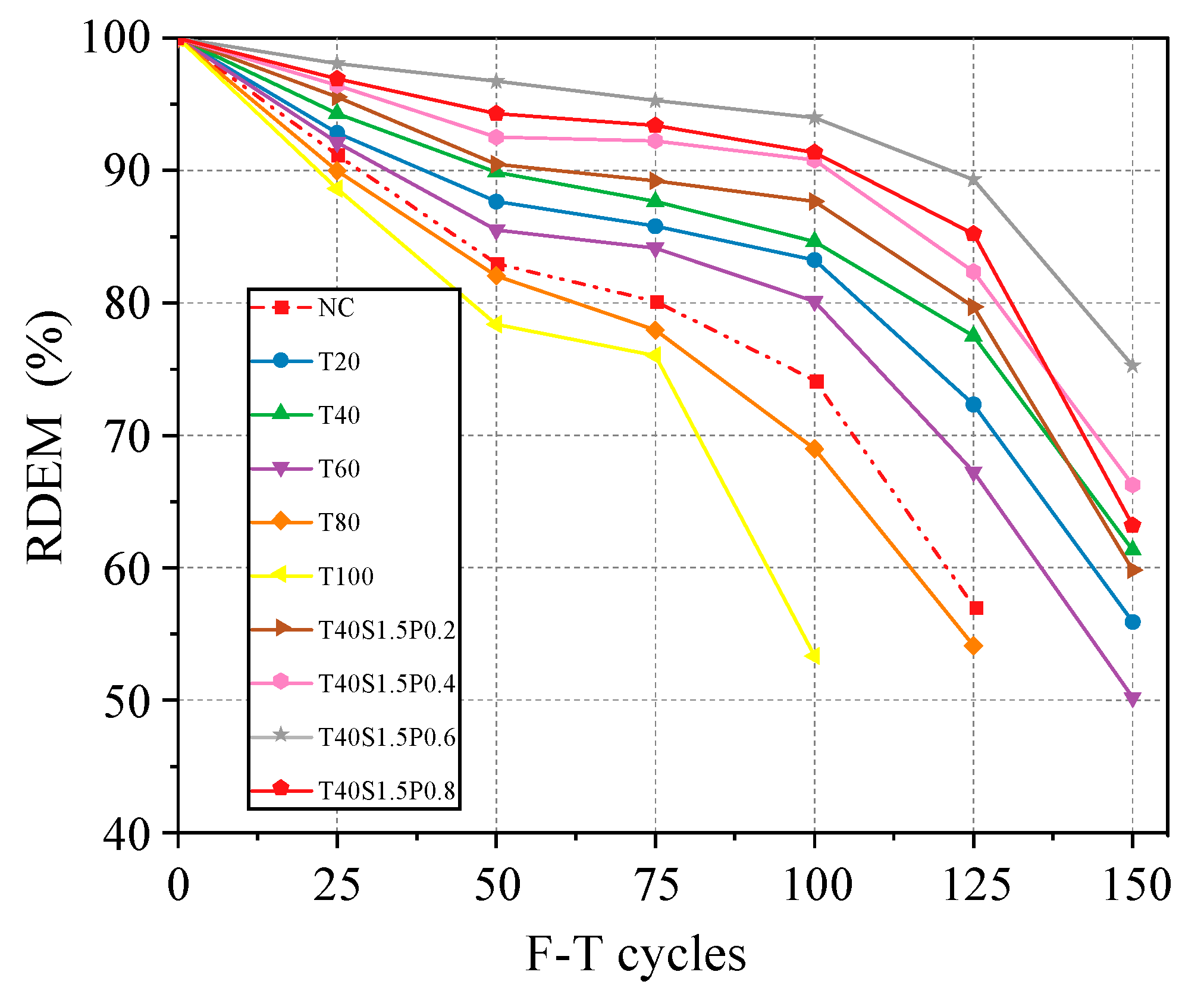
4.4. RDEM
Figure 15 presents the RDEM. The RDEM of each sample shows a slight decrease (except for T100) with fewer than 100 F–T cycles but declines rapidly between 100 and 150 cycles. This decrease in RDEM is primarily associated with the formation of pores and cracks. During the initial F–T cycles, diffused SO42− reacts with cement hydration products to produce expansion products, potentially causing micro-cracks. These expansion products fill the pores, thereby reducing RDEM loss. However, as the number of F–T cycles increases, more expansion products form, accelerating deterioration and significantly reducing RDEM. Additionally, after 100 and 125 F–T cycles, the RDEM of both T100 and T80 drops below 60%. However, after 150 F–T cycles, the RDEM of T40 also falls below 60%. This indicates that a higher replacement ratio of IOTs has a negative impact on RDEM. After fiber addition, the RDEM of each concrete exceeds 60% after 150 F–T cycles. Additionally, similar to the trends observed in fcu loss and mass loss, the PF content in the hybrid fiber decreases by 0.8%, resulting in a decreasing trend in RDEM.
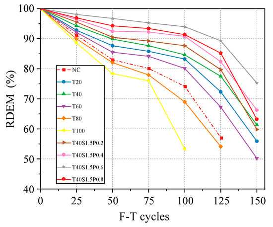
Figure 15.
REDM after sulfate F–T cycle.
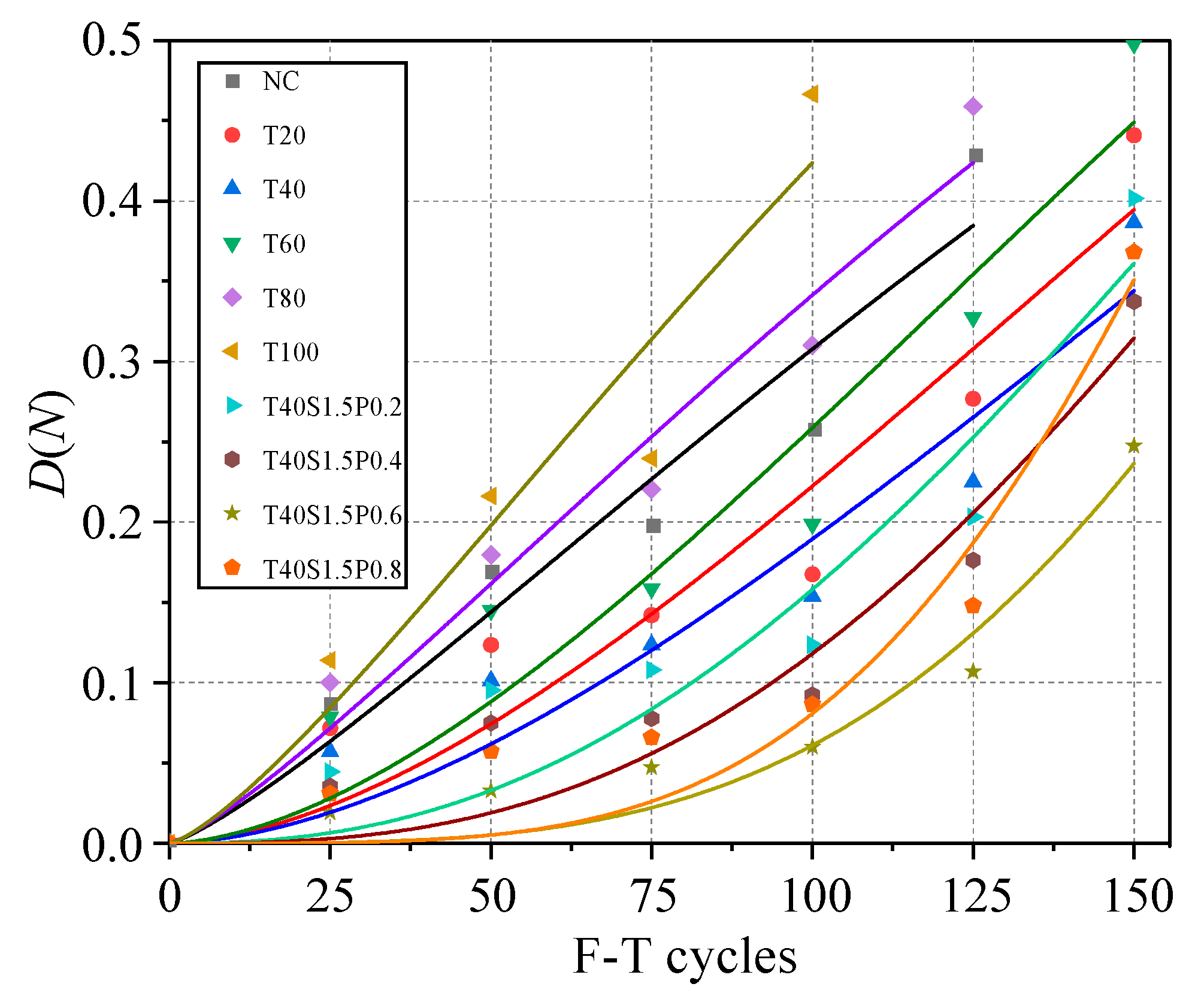
4.5. F–T Damage Evolution
Currently, various indices are available for evaluating concrete damage. Within this study, REDM is employed as the damage evaluation index, and the F–T damage level is characterized by Equation (3).
where D(N) is the damage coefficient, Ei is the RDEM after i-time F–T cycles, and E0 is the initial RDEM.
The Weibull failure model is a statistical model used to describe material failure and reliability analysis [64]. The Weibull failure model is widely applied in material science, engineering reliability, and life data analysis to predict the lifespan and failure probability of materials under different stress conditions. Hence, D(N) can be represented by Equation (4).
where α and β are the parameters.
The D(N) values following different F–T cycles in the 10% Na2SO4 solution are modeled using the least squares method, as shown in Figure 16. The parameters α and β, derived from the fitting procedure, are provided in Table 5. Based on the R2 values, it is evident that the Weibull distribution function accurately predicts the D(N).

Figure 16.
D(N) under varying F–T cycles.
Table 5.
Parameters of Weibull distribution.
4.6. Deterioration Mechanism of Sulfate F–T Cycle
During the initial stage of sulfate F–T cycles, SO42− diffuses into the matrix through the pores, creating tension on the pore wall. Furthermore, the diffused SO42− reacts with cement hydration products to produce gypsum (CaSO4·2H2O) and ettringite (3CaO·Al2O3·CaSO4·31H2O), as depicted in Equations (5) and (6). The filling effect of these products on pores significantly inhibits further SO42− diffusion into the matrix, thereby reducing the rate of deterioration. Over repeated F–T cycles, an accumulation of corrosion products occurs, exerting an expansion force on the inner pore wall. Due to the combined impact of expansion force and F–T force, rapid pore expansion occurs, leading to the formation of interconnected micro-cracks that accelerate matrix deterioration. This is manifested macroscopically by surface delamination of the specimen, coupled with rapid declines in mass, RDEM, and strength.
Na2SO4 + Ca(OH)2 + 2H2O → CaSO4·2H2O + 2Na2OH
4CaO·Al2O3·12H2O + 2Ca(OH)2 + 3Na2SO4 + 20H2O → 3CaO·Al2O3·CaSO4·31H2O + 6NaOH
5. Microanalysis
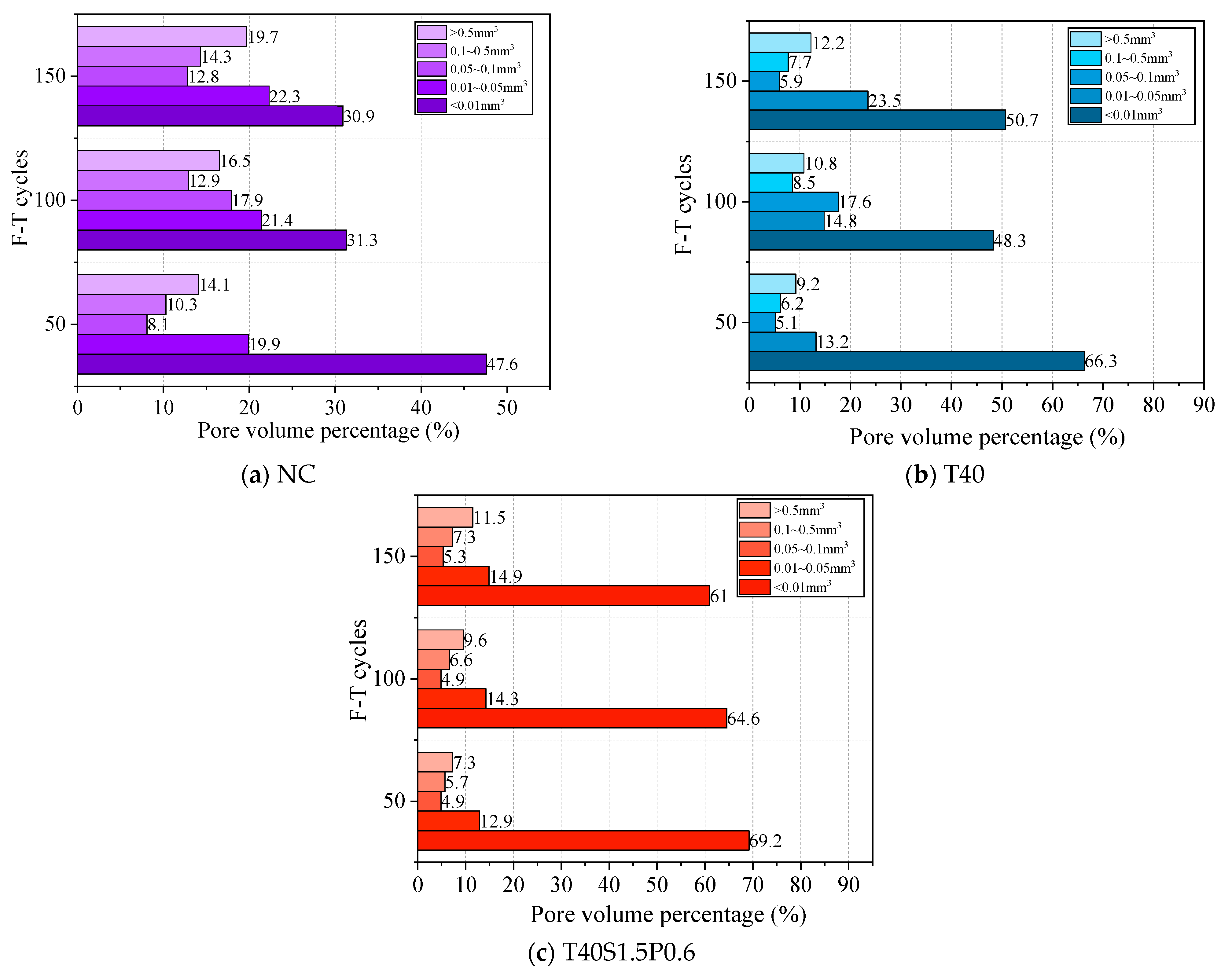
5.1. CT Pore Characteristics Analysis
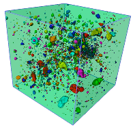
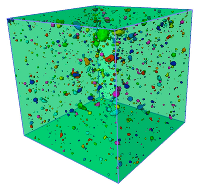
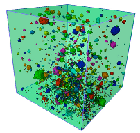
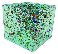
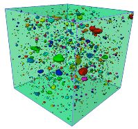
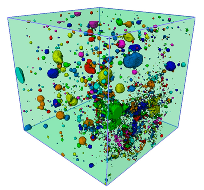
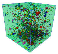
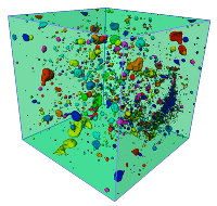
The evolution characteristics of internal pores in the specimens under various F–T cycles are presented in Table 6. A common trend is evident; as F–T cycles increase, both the quantity and scale of internal pores in NC, T40, and T40S1.5P0.6 increase. This is primarily attributed to continuous F–T cycles inducing the formation of new pores within the specimens, along with the connectivity, fusion, and expansion of pre-existing pores. Following 150 F–T cycles, the pores in NC exhibit a larger scale and a more concentrated distribution of large-scale pores. In contrast, T40 possesses a higher quantity of internal pores, albeit smaller in scale and relatively evenly distributed. Following fiber addition, the quantity of internal pores in T40S1.5P0.6 decreases further compared to NC, while enhancing the uniformity of pore distribution within the specimens.
Table 6.
3D distribution of pores of specimens after different F–T cycles.
Figure 17 illustrates the percentage of internal pore volume for each sample under various F–T cycles. With an increase in F–T cycles, the proportion of pores with internal pore volumes less than 0.01 mm3 decreased in NC, T40, and T40S1.5P0.6, whereas those with volumes between 0.01 and 0.05 mm3, 0.05 and 0.1 mm3, 0.1 and 0.5 mm3, and greater than 0.5 mm3 increased. Following 150 F–T cycles, the percentage of pores larger than 0.5 mm3 in NC, T40, and T40S1.5P0.6 was 19.7%, 12.2%, and 11.5%, respectively. Moreover, fiber incorporation effectively mitigated the development of large pores during F–T cycles.

Figure 17.
Pores volume percentage of specimens after different F–T cycles.
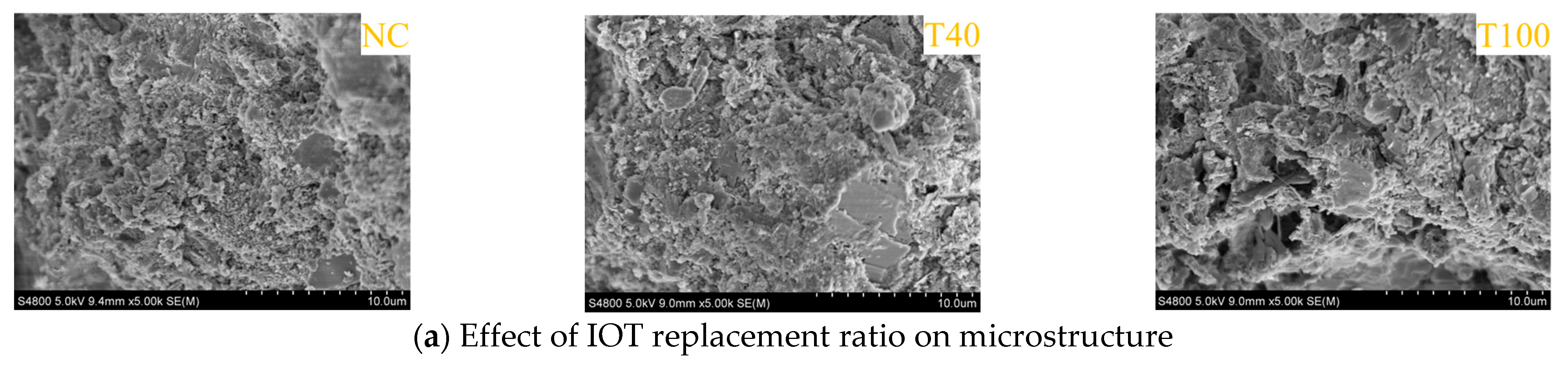
5.2. SEM Micromorphology Analysis
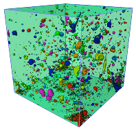
Figure 18 displays the SEM micromorphology of the concrete. In Figure 18a, it is evident that numerous pores, including connected pores and micro-pores, are large in NC, indicating a relatively loose microstructure. Comparatively, T40 exhibits significantly improved compactness throughout the matrix compared to NC. However, with a high replacement ratio of IOTs, T100 experiences an increase in the number of micro-holes, connecting holes, and cracks, leading to lower mechanical properties compared to other samples.

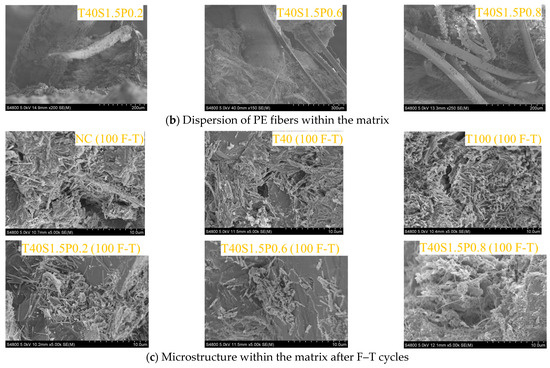
Figure 18.
SEM micromorphology.
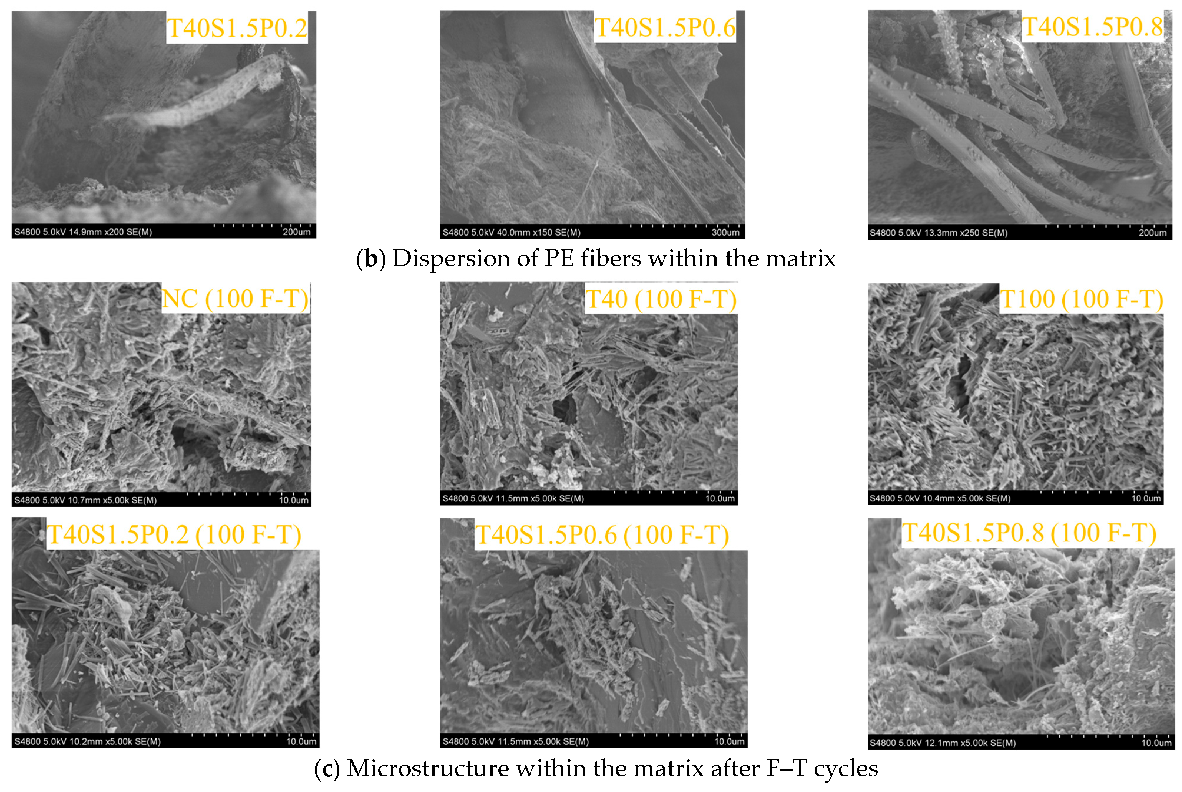
Figure 18b found that, as PF doping increased, the dispersion of its fibers within the matrix gradually deteriorated, leading to noticeable agglomeration. The dispersion of PF was found to be appropriate in T40S1.5P0.6, while the agglomeration phenomenon was evident in T40S1.5P0.8, indicating that the mechanical properties of T40S1.5P0.8 are lower than those of T40S1.5P0.6.
After 100 sulfate F–T cycles, Figure 18c illustrates the production of varying amounts of acicular ettringite and rod-like gypsum around the pores and cracks of concrete samples. The T40 matrix exhibits a relatively small amount of acicular ettringite compared to NC, primarily due to the improved compactness, which decreases the SO42− erosion rate. Conversely, T100 exhibits a higher abundance of acicular ettringite, suggesting increased penetration of SO42− due to more cracks and pores in the matrix, accelerating concrete sample erosion and diminishing adhesion between hydration products and aggregates. With the addition of fiber, the amount of ettringite in T40S1.5P0.2, T40S1.5P0.6, and T40S1.5P0.8 is lower than that in T40, primarily due to fiber incorporation refining the pore structure and reducing the erosion rate. However, it was found that, compared with T40S1.5P0.6, the incorporation of 0.8% PF leads to an increase in the accumulation of erosion products within the matrix due to fiber dispersion issues, while simultaneously causing a deterioration in the internal structural compactness of the matrix.
6. Conclusions
This paper extensively investigated the mechanical properties, sulfate F–T resistance, and microstructure of hybrid SF and PF reinforced IOT concrete. The following conclusions were drawn:
(1) The feasibility of using IOTs as a fine aggregate to replace RS was investigated based on composition and physical property analysis. The mechanical properties generally exhibited an initial increase followed by a decrease with an increasing IOT replacement ratio. The addition of mixed SF and PF improved the mechanical properties of IOT concrete. The fcu and fsts of T40S1.5P0.6 increased by 22.35% and 31.38%, which showed the best performance, compared to NC.
(2) Based on the test results, a relationship between fcu and fsts is proposed, and corresponding constants are determined. Furthermore, the fsts is calculated using the existing standard model, and it is observed that the error of the calculated fsts using the equation in this paper is small, which reflects the best reliability.
(3) Regarding sulfate F–T resistance, the surface damage, mass loss, RDEM, and fcu loss of IOT concrete initially decrease slowly and then rapidly with increasing F–T cycles. Moreover, the addition of mixed SF and PF significantly enhances the sulfate F–T resistance of the mixture, with T40S1.5P0.6 demonstrating superior performance. Based on the experimental results of RDEM, a Weibull damage model under F–T conditions is established, and certain damage parameters are proposed. The model correlates well with the experimental results.
(4) The CT results found that F–T cycles increase both the quantity and scale of internal pores in IOT concrete. Fiber incorporation effectively mitigated the development of large pores during F–T cycles.
(5) SEM results reveal that a high replacement ratio of IOTs increases the internal porosity of concrete and accelerates concrete deterioration after the sulfate F–T cycle. However, the addition of SF and PF reduces the amount of corrosion products.
Author Contributions
Conceptualization, J.W. and X.L.; methodology, J.W.; formal analysis, J.W.; investigation, X.L.; writing—original draft preparation, J.W.; funding acquisition, X.L. All authors have read and agreed to the published version of the manuscript.
Funding
This work was supported by the National Natural Science Foundation of China (No. 42207200), Science and Technology Research Project of Henan Province, China (No. 2319).
Data Availability Statement
Some or all data, models, or codes that support the findings of this study are available from the corresponding author upon reasonable request.
Conflicts of Interest
The authors declare no conflict of interest.
References
- Zuccheratte, A.; Freire, C.B.; Lameiras, F.S. Synthetic gravel for concrete obtained from sandy iron ore tailing and recycled polyethyltherephtalate. Constr. Build. Mater. 2017, 151, 859–865. [Google Scholar] [CrossRef]
- Fontes, W.C.; Mendes, J.C.; Da Silva, S.N.; Peixoto, R.A.F. Mortars for laying and coating produced with iron ore tailings from tailing dams. Constr. Build. Mater. 2016, 112, 988–995. [Google Scholar] [CrossRef]
- Osinubi, K.J.; Yohanna, P.; Eberemu, A.O. Cement modification of tropical black clay using iron ore tailings as admixture. Transp. Geotech. 2015, 5, 35–49. [Google Scholar] [CrossRef]
- Shettima, A.U.; Hussin, M.W.; Ahmad, Y.; Mirza, J. Evaluation of iron ore tailings as replacement for fine aggregate in concrete. Constr. Build. Mater. 2016, 120, 72–79. [Google Scholar] [CrossRef]
- Davila, R.B.; Fontes, M.; Pacheco, A.A.; Ferreira, M. Heavy metals in iron ore tailings and floodplain soils affected by the Samarco dam collapse in Brazil. Sci. Total Environ. 2019, 709, 136151. [Google Scholar] [CrossRef] [PubMed]
- Hossain, M.U.; Poon, C.S.; Lo, I.M.C.; Cheng, J.C.P. Comparative environmental evaluation of aggregate production from recycled waste materials and virgin sources by LCA. Resour. Conserv. Recycl. 2016, 109, 67–77. [Google Scholar] [CrossRef]
- Han, F.; Li, L.; Song, S.; Liu, J. Early-age hydration characteristics of composite binder containing iron tailing powder. Powder Technol. 2017, 315, 322–331. [Google Scholar] [CrossRef]
- Zhang, C.; Li, S. Utilization of iron ore tailing for the synthesis of zeolite A by hydrothermal method. J. Mater. Cycles Waste Manag. 2018, 20, 1605–1614. [Google Scholar] [CrossRef]
- Wang, X.; Yu, R.; Shui, Z.; Zhao, Z.; Song, Q.; Yang, B.; Fan, D. Development of a novel cleaner construction product: Ultra-high performance concrete incorporating lead-zinc tailings. J. Clean. Prod. 2018, 196, 172–182. [Google Scholar] [CrossRef]
- Tian, Z.X.; Zhao, Z.H.; Dai, C.Q.; Liu, S.J. Experimental Study on the Properties of Concrete Mixed with Iron Ore Tailings. Adv. Mater. Sci. Eng. 2016, 2016, 8606505. [Google Scholar] [CrossRef]
- Ugama, T.I.; Ejeh, S.P.; Amartey, D.Y. Effect of Iron Ore Tailing on the Properties of Concrete. Civ. Environ. Res. 2014, 6, 7. [Google Scholar]
- Argane, R.; Benzaazoua, M.; Hakkou, R.; Bouamrane, A. Reuse of base-metal tailings as aggregates for rendering mortars: Assessment of immobilization performances and environmental behavior. Constr. Build. Mater. 2015, 96, 296–306. [Google Scholar] [CrossRef]
- Aggarwal, Y.; Siddique, R. Microstructure and properties of concrete using bottom ash and waste foundry sand as partial replacement of fine aggregates. Constr. Build. Mater. 2014, 54, 210–223. [Google Scholar] [CrossRef]
- Ismail, Z.Z.; Al-Hashmi, E.A. Reuse of waste iron as a partial replacement of sand in concrete. Waste Manag. 2008, 28, 2048–2053. [Google Scholar] [CrossRef] [PubMed]
- Zhang, G.D.; Zhang, X.Z.; Zhou, Z.H.; Cheng, X. Preparation and Properties of Concrete Containing Iron Tailings/Manufactured Sand as Fine Aggregate. Adv. Mater. Res. 2014, 838–841, 152–155. [Google Scholar] [CrossRef]
- Xu, F.; Wang, S.; Li, T.; Liu, B.; Liu, K. The mechanical properties and resistance against the coupled deterioration of sulfate attack and freeze-thaw cycles of tailing recycled aggregate concrete. Constr. Build. Mater. 2020, 269, 121273. [Google Scholar] [CrossRef]
- Xu, F.; Wang, S.; Li, T.; Liu, B.; Zhou, Y. The mechanical properties of tailing recycled aggregate concrete and its resistance to the coupled deterioration of sulfate attack and wetting–drying cycles. Structures 2020, 27, 2208–2216. [Google Scholar] [CrossRef]
- Li, T.; Wang, S.; Xu, F.; Meng, X.; Zhan, M. Study of the basic mechanical properties and degradation mechanism of recycled concrete with tailings before and after carbonation. J. Clean. Prod. 2020, 259, 120923. [Google Scholar] [CrossRef]
- Xlab, C.; Ylab, D.; Xia, C.; Yan, S.; Rl, E.; Rwa, B.; Zpa, B. Environmental impact, durability performance, and interfacial transition zone of iron ore tailings utilized as dam concrete aggregates. J. Clean. Prod. 2021, 292, 126068. [Google Scholar]
- Banthia, N.; Gupta, R. Influence of polypropylene fiber geometry on plastic shrinkage cracking in concrete. Cem. Concr. Res. 2006, 36, 1263–1267. [Google Scholar] [CrossRef]
- Alnahhal, W.; Aljidda, O. Flexural behavior of basalt fiber reinforced concrete beams with recycled concrete coarse aggregates. Constr. Build. Mater. 2018, 169, 165–178. [Google Scholar] [CrossRef]
- Jalal, A.; Shafiq, N.; Nikbakht, E.; Kumar, R.; Zahid, M. Mechanical Properties of Hybrid Basalt-Polyvinyl Alcohol (PVA) Fiber Reinforced Concrete. Key Eng. Mater. 2017, 744, 3–7. [Google Scholar] [CrossRef]
- Kl, A.; Sw, A.; Xq, A.; Wei, D.C.; Zhao, N.A.; Tao, W.D.; Fan, X.A.; Bla, B. Study on the mechanical properties and microstructure of fiber reinforced metakaolin-based recycled aggregate concrete. Constr. Build. Mater. 2021, 294, 123554. [Google Scholar]
- Miao, C.; Ru, M.; Qian, T.; Wei, S. Effect of sulfate solution on the frost resistance of concrete with and without steel fiber reinforcement. Cem. Concr. Res. 2002, 32, 31–34. [Google Scholar] [CrossRef]
- Yan, F.; Lin, Z.; Zhang, D.; Gao, Z.; Li, M. Experimental study on bond durability of glass fiber reinforced polymer bars in concrete exposed to harsh environmental agents: Freeze-thaw cycles and alkaline-saline solution. Compos. Part B Eng. 2017, 116, 406–421. [Google Scholar] [CrossRef]
- Huang, X.; Ranade, R.; Li, V.C. Feasibility Study of Developing Green ECC Using Iron Ore Tailings Powder as Cement Replacement. J. Mater. Civ. Eng. 2013, 25, 923–931. [Google Scholar] [CrossRef]
- Huang, X.; Ranade, R.; Qian, Z.; Wen, N.; Li, V.C. Mechanical and thermal properties of green lightweight engineered cementitious composites. Constr. Build. Mater. 2013, 48, 954–960. [Google Scholar] [CrossRef]
- Huang, X.; Ranade, R.; Ni, W.; Li, V.C. Development of green engineered cementitious composites using iron ore tailings as aggregates. Constr. Build. Mater. 2013, 44, 757–764. [Google Scholar] [CrossRef]
- Zhu, Z.; Li, B.; Zhou, M. The Influences of Iron Ore Tailings as Fine Aggregate on the Strength of Ultra-High Performance Concrete. Adv. Mater. Sci. Eng. 2015, 2015, 1–6. [Google Scholar] [CrossRef]
- Bao, W.B.; Wang, C.H.; Zhang, S.F.; Huang, Z.Q. Experimental Study on Mechanical Properties of PVA Fiber Reinforced Tailings Cementitious Composites. Adv. Mater. Res. 2012, 598, 618–621. [Google Scholar] [CrossRef]
- Caggiano, A.; Gambarelli, S.; Martinelli, E.; Nistico, N.; Pepe, M. Experimental characterization of the post-cracking response in Hybrid Steel/Polypropylene Fiber-Reinforced Concrete. Constr. Build. Mater. 2016, 125, 1035–1043. [Google Scholar] [CrossRef]
- Banthia, N.; Gupta, R. Hybrid fiber reinforced concrete (HyFRC): Fiber synergy in high strength matrices. Mater. Struct. 2004, 37, 707–716. [Google Scholar] [CrossRef]
- Kb, A.; Kr, A.; Akv, A.; Uv, A.; Sks, B. Effect of dumped iron ore tailing waste as fine aggregate with steel and basalt fibre in improving the performance of concrete— ScienceDirect. Mater. Today Proc. 2021, 46, 7624–7632. [Google Scholar]
- Afroughsabet, V.; Ozbakkaloglu, T. Mechanical and durability properties of high-strength concrete containing steel and polypropylene fibers. Constr. Build. Mater. 2015, 94, 73–82. [Google Scholar] [CrossRef]
- Wang, Y.; Zhang, S.; Niu, D.; Fu, Q. Quantitative evaluation of the characteristics of air voids and their relationship with the permeability and salt freeze-thaw resistance of hybrid steel-polypropylene fiber-reinforced concrete composites. Cem. Concr. Compos. 2022, 125, 104292. [Google Scholar] [CrossRef]
- Xu, F.; Wang, S.; Li, T.; Xu, F.; Wang, S.; Li, T.; Liu, B.; Li, B.; Zhou, Y. Mechanical properties and pore structure of recycled aggregate concrete made with iron ore tailings and polypropylene fibers. J. Build. Eng. 2021, 33, 101572. [Google Scholar] [CrossRef]
- Li, J.S.; Ren, W.Y.; Zhang, A.J.; Li, S.; Tan, J.; Liu, H. Mechanical Properties and Microstructure Analysis of Cement Mortar Mixed with Iron Ore Tailings. Buildings 2023, 13, 13010149. [Google Scholar] [CrossRef]
- Lv, X.; Shen, W.; Wang, L.; Dong, Y.; Zhang, J.; Xie, Z. A comparative study on the practical utilization of iron tailings as a complete replacement of normal aggregates in dam concrete with different gradation. J. Clean. Prod. 2019, 211, 704–715. [Google Scholar] [CrossRef]
- Duan, H.; Liu, H.; Li, B.; Wang, Z.; Gao, H. Mechanical Properties and Mechanism Analysis of Graphite Tailings Environment-Friendly Concrete. Materials 2022, 15, 15248870. [Google Scholar] [CrossRef] [PubMed]
- GB/T14684-2011; Sand for Construction. Standardization Administration of China: Beijing, China, 2012.
- GB/T 50081-2019; Standard for Test Methods of Physical and Mechanical Properties of Concrete. State Administration for Market Regulation: Beijing, China, 2019.
- GB/T50082-2009; Standard for Test Methods of Long-Term Performance and Durability of Ordinary Concrete. Ministry of Construction of the People’s Republic of China: Beijing, China, 2009.
- Zhao, N.; Wang, S.; Wang, C.; Quan, X.; Li, B. Study on the durability of engineered cementitious composites (ECCs) containing high-volume fly ash and bentonite against the combined attack of sulfate and freezing-thawing (F-T). Constr. Build. Mater. 2020, 233, 117313. [Google Scholar] [CrossRef]
- Du, J.; Ye, J.; Li, G. Inhibitory effects of chloride ions on concrete sulfate attack in the marine adsorption environment. Mar. Georesour. Geotechnol. 2016, 35, 371–375. [Google Scholar] [CrossRef]
- Peng, L.; Ying, C.; Zya, C.; Zla, C. Effect of sulfate solution concentration on the deterioration mechanism and physical properties of concrete. Constr. Build. Mater. 2019, 227, 116641. [Google Scholar]
- GB/T50080-2002; Standard for Test Method of Performance on Ordinary Fresh Concrete. Ministry of Construction of the People’s Republic of China: Beijing, China, 2003.
- Yue, Y.; Zhou, Y.; Xing, F.; Gong, G.; Hu, B.; Guo, M. An industrial applicable method to improve the properties of recycled aggregate concrete by incorporating nano-silica and micro-CaCO3. J. Clean. Prod. 2020, 259, 120920. [Google Scholar] [CrossRef]
- Jiang, C.; Ke, F.; Fei, W.; Da, C. Experimental study on the mechanical properties and microstructure of chopped basalt fibre reinforced concrete. Mater. Des. 2014, 58, 187–193. [Google Scholar] [CrossRef]
- Dandautiya, R.; Singh, A.P. Utilization potential of fly ash and copper tailings in concrete as partial replacement of cement along with life cycle assessment. Waste Manag. 2019, 99, 90–101. [Google Scholar] [CrossRef] [PubMed]
- Meng, Y.; Ni, W.; Zhang, Y. Current state of ore tailings reusing and its future development in China. China Mine Eng. 2010, 5, 1–8. [Google Scholar]
- Chan, R.; Santana, M.A.; Oda, A.M.; Paniguel, R.C.; Galobardes, I. Analysis of Potential Use of Fibre Reinforced Recycled Aggregate Concrete for Sustainable Pavements. J. Clean. Prod. 2019, 218, 183–191. [Google Scholar] [CrossRef]
- High, C.; Seliem, H.M.; El-Safty, A.; Rizkalla, S.H. Use of basalt fibers for concrete structures. Constr. Build. Mater. 2015, 96, 37–46. [Google Scholar] [CrossRef]
- Wang, L.; Zhou, S.H.; Shi, Y.; Tang, S.W.; Chen, E. Effect of silica fume and PVA fiber on the abrasion resistance and volume stability of concrete. Compos. Part B Eng. 2017, 130, 28–37. [Google Scholar] [CrossRef]
- Xiao, J.; Li, W.; Sun, Z.; Lange, D.A.; Shah, S.P. Properties of interfacial transition zones in recycled aggregate concrete tested by nanoindentation. In Cement and Concrete Composites; Elsevier: Amsterdam, The Netherlands, 2013. [Google Scholar]
- Jz, A.; Kn, B.; Ys, A.; Ys, B. An evaluation of iron ore tailings characteristics and iron ore tailings concrete properties—ScienceDirect. Constr. Build. Mater. 2021, 286, 122968. [Google Scholar]
- Ahmed, T.; Elchalakani, M.; Basarir, H.; Karrech, A.; Yang, B. Development of ECO-UHPC utilizing gold mine tailings as quartz sand alternative. Clean. Eng. Technol. 2021, 4, 100176. [Google Scholar] [CrossRef]
- Zhong, H.; Zhang, M. Experimental study on engineering properties of concrete reinforced with hybrid recycled tyre steel and polypropylene fibres. J. Clean. Prod. 2020, 259, 120914. [Google Scholar] [CrossRef]
- Laq, A.; Ba, B.; Aa, C. Combined effects of supplementary cementitious materials (silica fume, GGBS, fly ash and rice husk ash) and steel fiber on the hardened properties of recycled aggregate concrete. Constr. Build. Mater. 2020, 263, 120636. [Google Scholar]
- Ahmadi, M.; Farzin, S.; Hassani, A.; Motamedi, M. Mechanical properties of the concrete containing recycled fibers and aggregates. Constr. Build. Mater. 2017, 144, 392–398. [Google Scholar] [CrossRef]
- Kassem, M.; Soliman, A.; El Naggar, H. Sustainable approach for recycling treated oil sand waste in concrete: Engineering properties and potential applications. J. Clean. Prod. 2018, 204, 50–59. [Google Scholar] [CrossRef]
- Gao, S.; Guo, L. Utilization of coal gangue as coarse aggregates in structural concrete. Constr. Build. Mater. 2021, 268, 121212. [Google Scholar] [CrossRef]
- Cheng, Y.; Wei, S.; Scrivener, K. Mechanism of expansion of mortars immersed in sodium sulfate solutions. Cem. Concr. Res. 2013, 43, 105–111. [Google Scholar]
- Pigeon, M.; Gagné, R.; Foy, C. Critical air-void spacing factors for low water-cement ratio concretes with and without condensed silica fume. Cem. Concr. Res. 1987, 17, 896–906. [Google Scholar] [CrossRef]
- Weibull, W. A statistical distribution function of wide applicability. J. Appl. Mech. 1951, 18, 293–297. [Google Scholar] [CrossRef]


Disclaimer/Publisher’s Note: The statements, opinions and data contained in all publications are solely those of the individual author(s) and contributor(s) and not of MDPI and/or the editor(s). MDPI and/or the editor(s) disclaim responsibility for any injury to people or property resulting from any ideas, methods, instructions or products referred to in the content. |
© 2024 by the authors. Licensee MDPI, Basel, Switzerland. This article is an open access article distributed under the terms and conditions of the Creative Commons Attribution (CC BY) license (https://creativecommons.org/licenses/by/4.0/).