Article

Mechanical Properties and Energy Damage Evolution Mechanism of Basalt Fiber-Modified Tailing Sand Cementation and Filling Body Mechanics

1
School of Resources and Environmental Engineering, Jiangxi University of Science and Technology, Ganzhou 341000, China
2
School of Resource and Construction Engineering, Gannan University of Science and Technology, Ganzhou 341000, China
*
Author to whom correspondence should be addressed.
Buildings 2024, 14(6), 1851; https://doi.org/10.3390/buildings14061851
Submission received: 5 May 2024 / Revised: 5 June 2024 / Accepted: 14 June 2024 / Published: 18 June 2024
(This article belongs to the Section Building Materials, and Repair & Renovation)

Abstract

:
In order to investigate the mechanical properties of basalt fiber-doped tailing sand cemented filler and the evolution of energy damage, a uniaxial compression test was carried out on the basalt fiber-doped tailing sand cemented filler specimens to analyze the energy dissipation characteristics, and the damage constitutive equations with different basalt fiber contents were established based on damage mechanics. The results show that with the increase of fiber doping and fiber length, the uniaxial compressive strength and ductility of the filling body show a trend of increasing and then decreasing; the optimal value of fiber doping is 0.6%, and the optimal value of fiber length is 9 mm; the total strain energy, elastic strain energy and dissipation energy of basalt fiber-modified tailing sand cemented filling body at peak stress show a trend of increasing and then decreasing, and the energy dissipation energy of the filling body shows a trend of increasing and then decreasing. The energy dissipation energy shows a trend of increasing and then decreasing, and the energy dissipation energy shows a trend of increasing and then decreasing. The total strain energy, elastic strain energy, and dissipation energy at the peak stress show a trend of decreasing after increasing with the fiber doping and fiber length, and the energy damage evolution process can be divided into four stages: no damage stage, stable damage development stage, accelerated damage growth stage, and damage destruction; in addition, the existing damage constitutive model of the fiber-filled body was optimized, and the damage correction factor was introduced to obtain the damage constitutive model of the filled body with different fiber contents, and finally, after the verification of experimental and theoretical models, it was found that the two stress–strain curves coincided well. Finally, after the test and theoretical model verification, it is found that the stress–strain curves of the two are in good agreement, which indicates that the established theoretical model has a certain reference value for engineering practice, and at the same time, it has certain limitations.

1. Introduction

With the shift from shallow mining to deep mining [1], the tailing cemented filler mining method has been widely used, which not only solves the problem of secondary utilization of tailing and other wastes but also ensures the safety of the underground mining process [2]. The strength of the filling body is a key factor in the safe and efficient implementation of the fill mining method. Therefore, the mechanical properties of the filling body have become the biggest problem for engineers and technicians, and its mechanical properties are susceptible to a variety of factors, such as materials, ash–sand ratio, admixtures, and so on. Aiming at these factors, many scholars have researched the mechanical properties of tailing sand cemented filler. For example, Mitchell et al. [3] proposed the first application of fibers to mine backfill, and they found that the addition of fibers increased the unconfined compressive strength (UCS) of the backfill and reduced the cement content; Chen et al. [4] explored the effect of PP fibers on the UCS and microstructural properties of cement tailing slurry. They found that the effect of fiber content on cement tailing slurry was considered to be higher than that of fiber length; Zhao et al. [5] carried out a study on the early mechanical properties and damage constitutive model of tailing sand filler under the action of different fibers, and the results showed that the enhancement effect of mixed fibers on the mechanical properties of tailing sand filler was better than that of single fiber; Hou et al. [6] investigated the effect of fiber and rice husk ash on the performance of ultrafine tailing sand cemented filler, the results show that the appropriate amount of fiber and rice husk ash can effectively inhibit the destruction of ultrafine tailing sand filler specimens and improve its compressive strength.; YI et al. [7] studied the influence of PP fibers on the UCS of the filling. It is considered that fiber increases UCS and reduces the loss of post-peak strength.; Cao et al. [8] conducted an experimental study on the early strength, toughness, and microstructure of three different types of fiber-reinforced tailing sand cemented fillers and found that all three types of fibers can make the strength and toughness of the fillers significantly improved and can make the fillers still maintain high integrity after being damaged.
The above studies have shown that the incorporation of fibers can effectively improve the mechanical properties of the filler. However, the deformation and damage of a filled body specimen is essentially a process of its internal damage accumulation, accompanied by energy absorption and dissipation [9]. It is of great significance to study the mechanism and process of energy damage evolution when it is subjected to external loading and to establish the damage eigenstructure model based on it to study the damage process of the filling body, and many scholars have carried out much research on the mechanism of energy damage evolution and its damage eigen structure equations when it is subjected to external loading, and they have achieved great results. Cheng Aiping and others [10] investigated the damage evolution law of different sizes of cemented fillers, and the results showed that the uniaxial compressive strength of the fillers increased firstly and then decreased with the increase of the size; Zhou et al. [11] investigated the effect of loading mode on the mechanical properties and damage characteristics of tailing sand cemented filler and its fractal dimension, revealing the differences in the mechanical properties of the filler under different loading modes; Liu et al. [12,13] studied the damage evolution law of tailing sand cemented filling with different ratios, and analyzed the problem of reasonable matching mechanism between surrounding rock and filling body; Hou et al. [14] carried out uniaxial compression tests on the filling body under different maintenance ages and constructed damage constitutive equations based on the damage mechanics theory, which showed that the extension of the maintenance age could improve the compressive strength of the filling body, and the reliability of the equations was also verified by combining the theory and tests; Zhao et al. [15] investigated the evolution law of granite energy at different loading rates, and the results showed that the damage variable of the rock samples increased with the increase of loading rate and the total strain energy increased.
In summary, fiber is added as an admixture inside the filling body, which not only improves its mechanical properties but also maintains the stability of the filling body. Common fibers are polypropylene fibers, glass fibers, and steel fibers; however, these fibers are synthetic. Synthetic fibers are not only expensive, but their production process easily causes a waste of resources and is very likely to endanger people’s health [16]. Basalt fiber (BF) is a mineral fiber that exists in volcanic rock [17], belonging to the natural fiber, and because of its excellent mechanical properties and affordability, comprehensive cost-effectiveness is very high [18,19,20] and, in line with the requirements of green environmental protection, it has gradually received attention. At present, scholars have performed many experimental studies on basalt fibers to improve the mechanical properties of concrete [21,22,23,24,25], but there are fewer studies on various aspects of the mechanical properties of the cemented tailings backfilling with basalt fibers (BFCTB), so it is necessary to carry out the corresponding research in this area to promote the application of basalt fibers in the field of tailing sand filler with reference value and guiding significance.
Therefore, the work in this paper selects basalt fiber as a fiber material to enhance the strength and overall stability of the tailing sand cemented filler and investigates the effect of basalt fiber doping as well as length and age of maintenance on the mechanical properties of the tailing sand cemented filler. In addition, it carries out research on the evolution mechanism of energy damage under different basalt fiber doping, constructs the damage constitutive equation, analyzes its energy dissipation law, and provides partial theoretical support for basalt fiber-reinforced tailing sand cemented filler to be applied in the mining airspace and to promote safe production.

2. Experimental Materials and Program

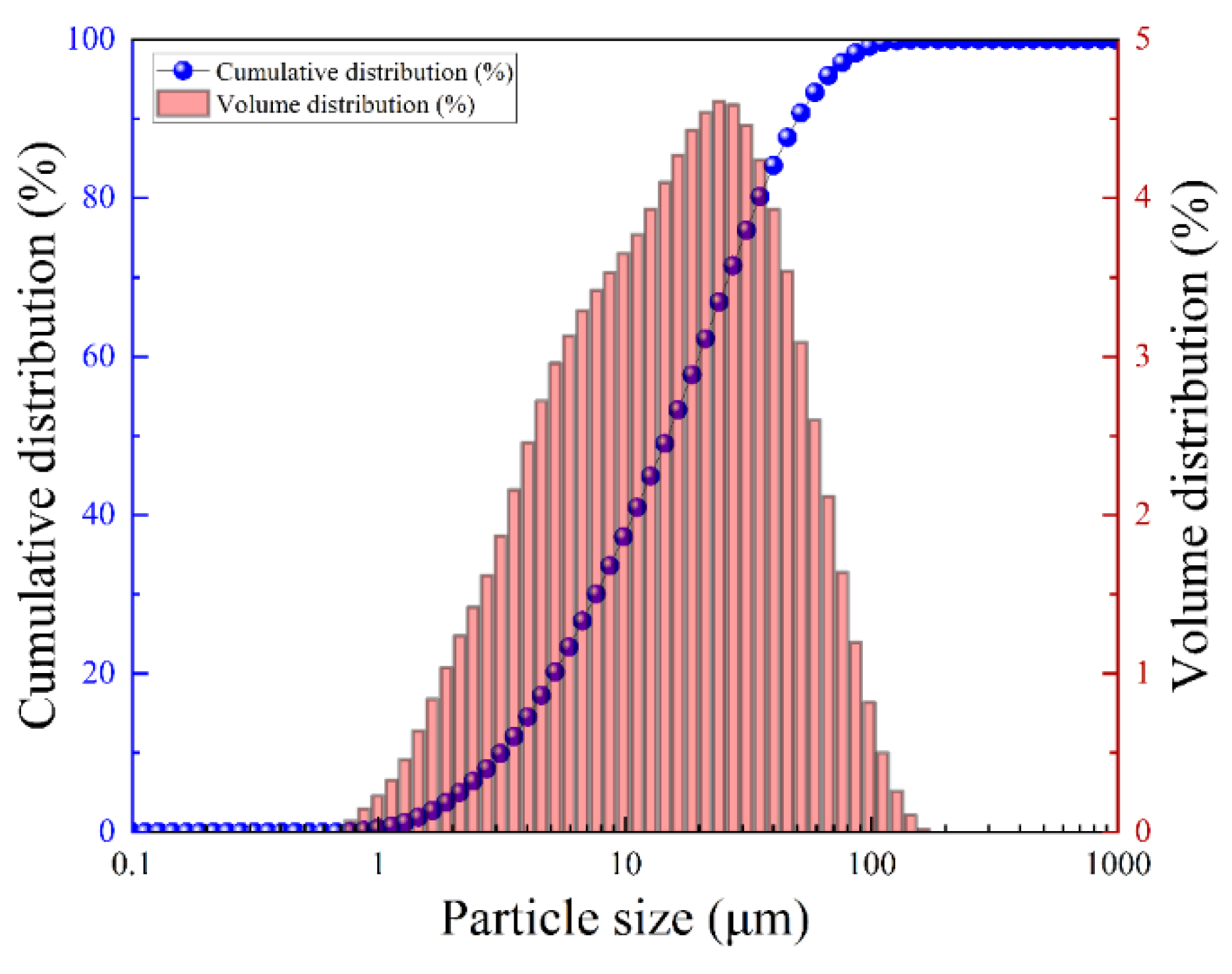
2.1. Experimental Materials

The whole tailing sand selected for the tests in this paper came from an iron ore mine and was transported to the laboratory after a natural drying process. A laser particle size meter (Winner 2000 China Jinan Huaxing Test Equipment Co.) and X-ray Perspex spectroscopy (XRF PANalytical B.V.) were used to analyze and test the physicochemical properties of the whole tailing sand of the mine. The results of the cumulative distribution of the tailing sand particle size were obtained as shown in Figure 1, and the composition of the chemical constituents is shown in Table 1. As can be seen in Figure 1, particles smaller than 2 μm particle size accounted for about 5%, and particles smaller than 20 μm particle size accounted for about 50%, and the grain size of this tailing sand belongs to the fine-grained class. The cementitious material is composite silicate cement with the grade P.O42.5R. The chemical composition of tailing sand and cement is shown in Table 1, and the basalt fibers (BF) in the test are high-strength basalt fibers produced by Changsha Lixing Building Materials, with lengths of 3 mm, 6 mm, 9 mm, and 12 mm, respectively. Some of the physical parameters of basalt fibers are shown in Table 2. It can be seen from Table 2 that the tensile strength of the basalt fiber used in the experiment is 3000–3500 Mpa, and the elastic modulus is 90–110 GPa, indicating that the fiber material used in the experiment has a high elastic modulus and tensile strength.

2.2. Experimental Program

This experiment is based on the filling ratios commonly used in mining practice, and a gray-to-sand ratio of 1:6 and a constant slurry concentration of 72% were selected during the test. The set maintenance ages were 3 d, 7 d, and 28 d. Modification of tailing sand cemented filler by mixing basalt fibers of different contents and lengths was investigated. For a fiber length of 6 mm, the content was varied by 0.2%, 0.4%, 0.6%, and 0.8%; fixed fiber content of 0.6% and changed fiber length to 3 mm, 6 mm, 9 mm, and 12 mm. Details of the experimental protocol are shown in Table 3. Three specimens were made for each group, and the results were averaged.

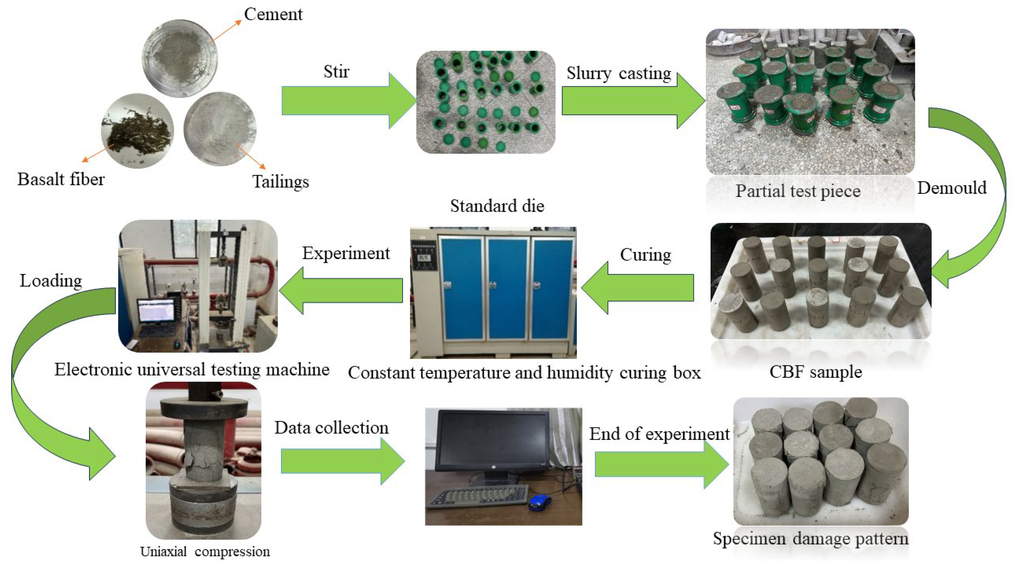
2.3. Experimental Methods and Specimen Preparation

Different proportions of materials were mixed to prepare the specimens, as specified in the program: (1) First, we mixed the tailing sand and cement for 5 min and set aside. (2) Subsequently, the evenly mixed dry materials were continuously stirred, with the fibers being incrementally introduced during the mixing process. Stirring ceased when the fiber was evenly distributed and did not clump together. (3) Water was added to the evenly stirred dry materials, and the entire mixture was stirred for an additional 5 min to produce the tailings filling slurry. The tailings filling slurry was promptly and evenly injected into cylindrical molds measuring 50 mm × 100 mm. (4) The cylindrical molds were put with slurry into the standard curing box (temperature: 20 ± 1 °C, relative humidity: 95%) after 24 h, demolded and grouped and numbered, and finally put each group of specimens in the curing box to continue to curing to the corresponding age.
The compressive strength experimental test using a WDW-20 electronic universal testing machine, a maximum load of 600 kN, accuracy of ±1%, and a resolution of 0.1 kN. The loading rate was set to 0.5 mm/min. The specimen preparation process and compression process of this experiment are shown in Figure 2.

3. Experimental Results and Analysis

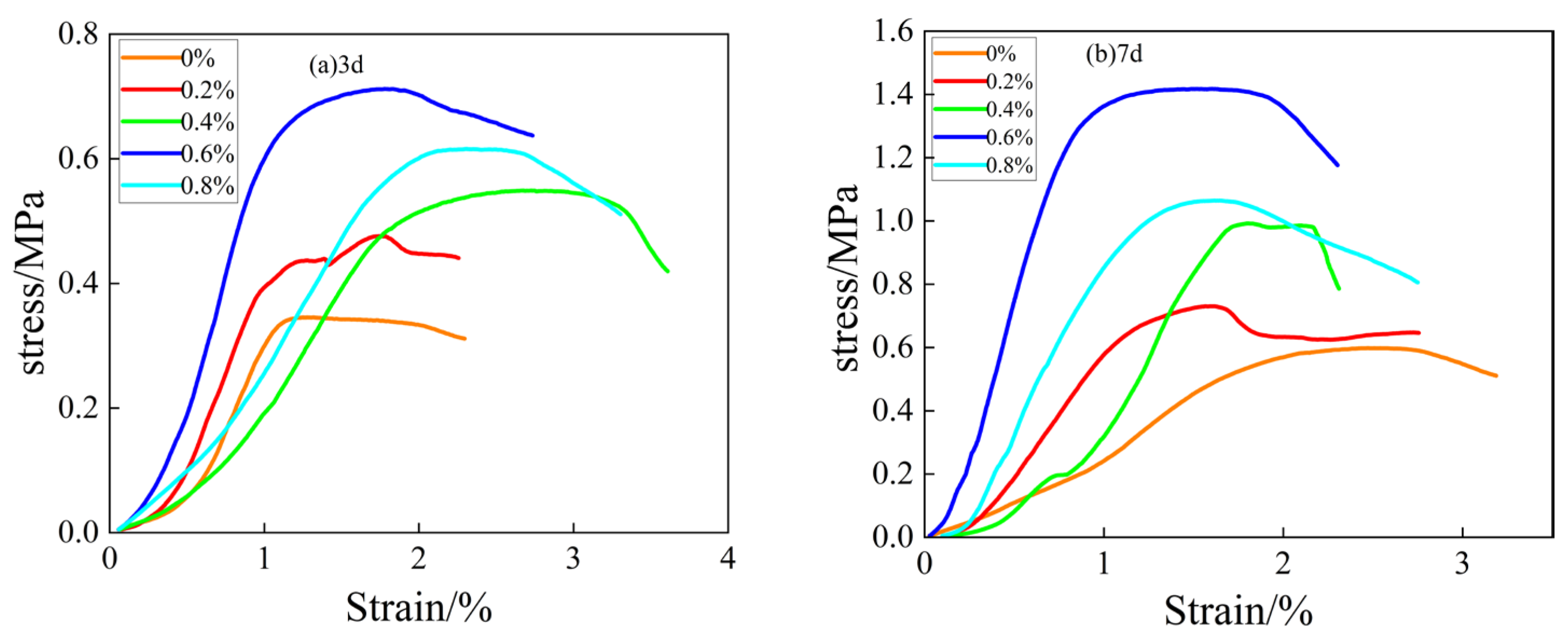
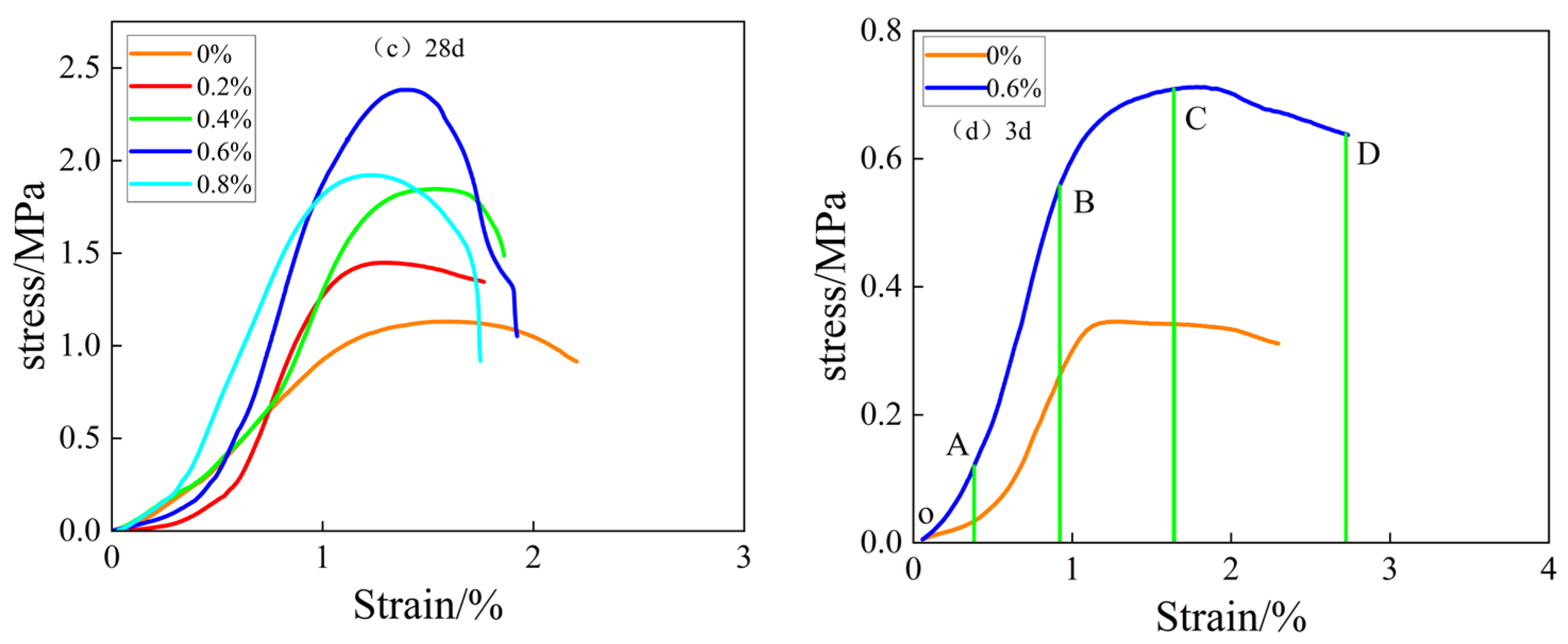
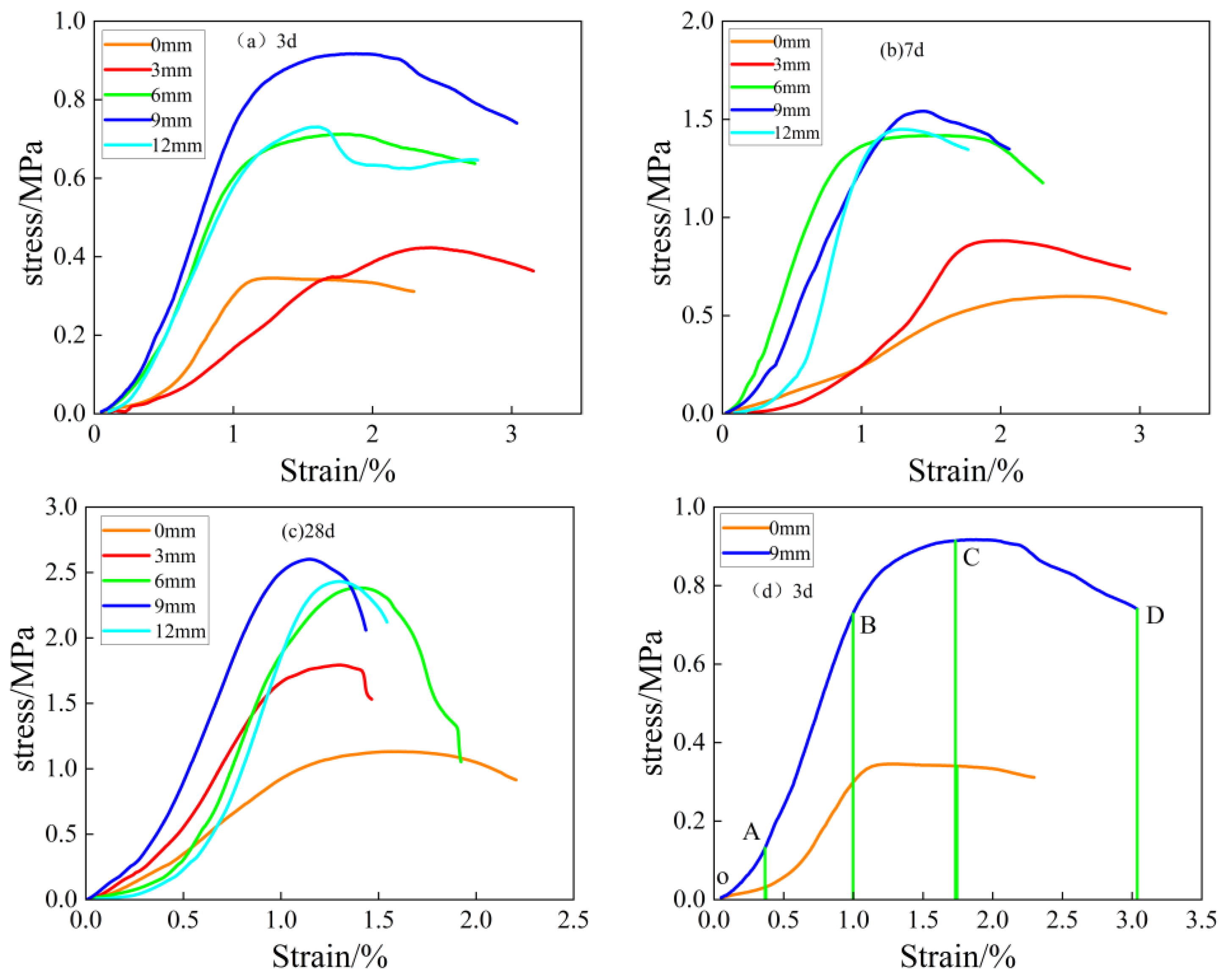
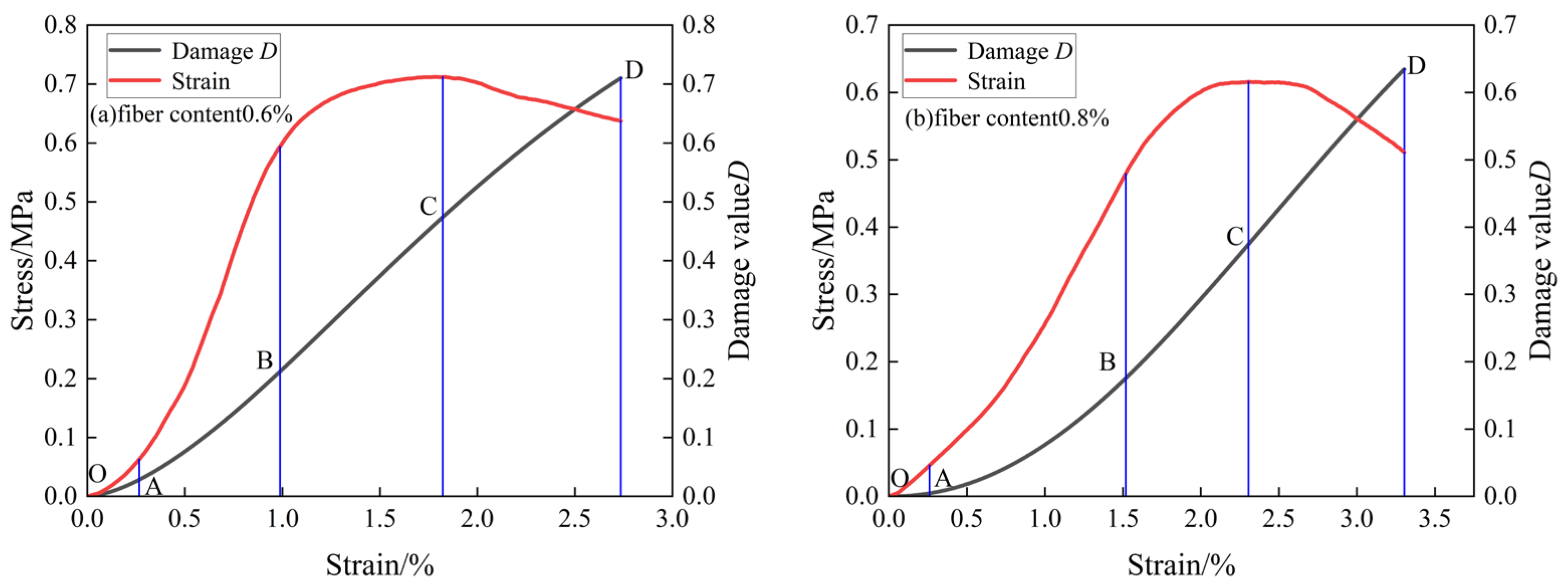
3.1. Morphological Characteristics of the Stress–Strain Curve of the Filling Body

According to the mechanical properties of the basalt fiber-doped tailing sand cemented filler, the corresponding stress–strain curves were obtained and further analyzed to reveal the morphological characteristics of the stress–strain curves of the filler under uniaxial compression. Figure 3 and Figure 4 show the stress–strain curves of the filled bodies with different basalt fiber contents and fiber lengths at different ages under uniaxial compression. From Figure 3 and Figure 4, it can be seen that the stress–strain curve of the filling body without added fibers decreased faster when the specimen of the filling body was subjected to the external load exceeding the peak stress, while the stress–strain curve of the filling body specimen subjected to the external load exceeding the peak stress with added basalt fibers decreased slower, indicating that the incorporation of the fibers improved the resistance to deformation and damage of the filling body [26]. In addition, the effect of changes in the curing times on the stress–strain curve of the filling body is mainly focused on the peak stress, while the increase in fiber content and fiber length can not only increase the level of the peak stress but can also affect the descending phase of the stress–strain curve.
Finally, the deformation damage of the filled body specimen was divided into stages with a curing time of 3 days, fiber doping of 0.6%, and a fiber length of 9 mm, and Figure 3d and Figure 4d show the results of the deformation damage stages of the stress–strain curve of the filled body with fiber doping of 0.6% and fiber length of 9 mm at the curing time of 3 days, respectively.
As can be seen from the Figure, the deformation damage of basalt fiber-doped tailing sand cemented filler under uniaxial loading can be divided into four stages:
(1)
Initial pore compacting stage (OA). At this stage, there are initial pores in the interior of the filling body, and with the increase of external load, the pores are gradually compacted. It can be seen from the Figure that the curves of the specimens without fibers show a more pronounced “concave” shape, whereas the curves of the fibers are less pronounced. The reason for this is that the inclusion of fibers fills the initial pores in the filled specimens, thus making the compaction of the filled bodies less pronounced at this stage;
(2)
Linear elastic deformation stage (AB). At this stage, the stress–strain curve of the filling body is approximately straight, and the stress increases approximately linearly with the strain. The inclusion of an appropriate amount of basalt fiber improves the strength of the filling body to a certain extent, further blocking the crack expansion and extension, but the specimen of the filling body at this time has not yet reached the threshold of destruction;
(3)
Yield damage stage (BC). At this stage, new cracks are created inside the filling body, the stress growth rate begins to slow down, and the stress–strain curve of the filling body shows a “convex” pattern. The stress value of the filling body at point C is the peak stress, and when the stress value exceeds the peak stress, the filling body enters the post-peak damage stage. It can be found that the strain at peak stress increases with the increase of basalt fiber doping.
(4)
Post-peak destruction phase (CD). At this stage, the stress in the filling body shows a tendency to decrease with increasing axial strain, and macroscopic main cracks appear on the surface of the filled body specimen. When the stress value reaches point D, there is overall damage to the filled body specimen, but the stress does not always drop to 0, indicating that the filled body specimen still has a certain residual strength after destruction [27]. At the same time, it shows that the filling body still has a certain bearing capacity after damage [28], and with the prolongation of the age of maintenance as well as the increase of the fiber content and length, its residual stress increases accordingly. The reason for this is that the fibers play a bridging and crack-blocking role inside the filler [29], maintaining the overall stability of the specimen. The compressive strength at a strain of 2.25% (at which time the stress–strain curve tends to flatten) was used as an evaluation criterion for ductility [30], and it was found that the post-peak ductility of the specimens was the best when the fiber doping was 0.6%, and the fiber length was 9 mm.

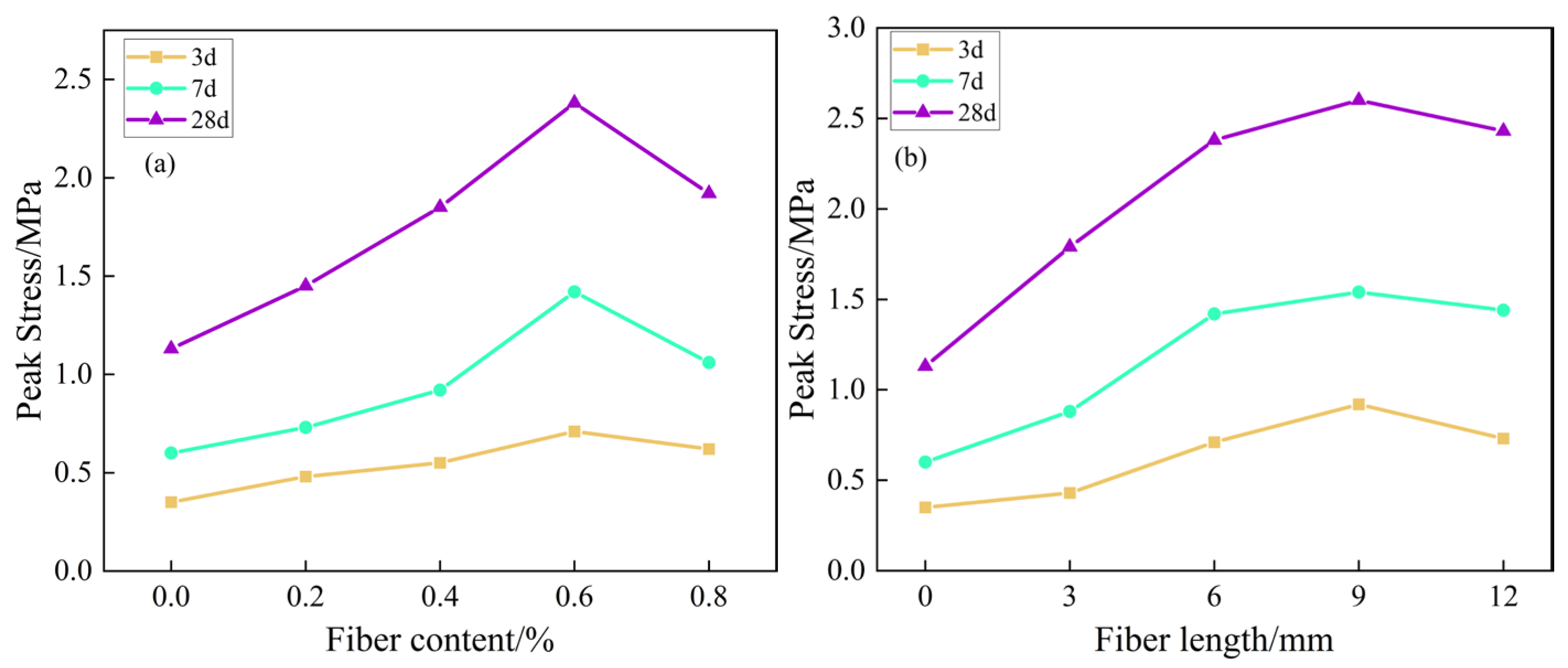
3.2. Effect of Fiber Dosage and Fiber Length on Uniaxial Compressive Strength of Filled Bodies

Figure 5 shows the uniaxial compressive strength of the basalt fiber-content tailing sand cemented filler as a function of fiber dosage and fiber length.
Figure 5a shows the relationship between compressive strength and fiber dosage. From Figure 5a, it can be seen that with the increase of the age of maintenance, regardless of the fiber dosage, the uniaxial compressive strength of the BFCTB specimen is increasing. For the same age, the uniaxial compressive strength of BFCTB specimens showed a general trend of increasing and then decreasing as the basalt fiber doping increased from 0% to 0.8%. It can be seen that the compressive strength of the BFCTB specimens at three different ages are all highest at 0.6% basalt fiber doping, indicating the existence of an optimal range of fiber content. Taking the curing time for 28d as an example, when the length of basalt fiber is 6 mm, and the fiber content grows from 0 to 0.2%, 0.4%, and 0.6%, the compressive strength of the filling body is increased by 29.2%, 61.1%, and 96.7%, respectively, but when the fiber content grows to 0.8%, the uniaxial compressive strength of the filling body decreases by 21.2% compared to that with the fiber content of 0.6%. It indicates that the addition of an appropriate amount of basalt fibers is beneficial to improve the uniaxial compressive strength of the filled body. The appropriate amount of basalt fibers can be uniformly distributed inside the tailing sand cemented filler specimen, which plays a bridging role [28], bears part of the load, and maintains the integrity of the filler specimen. However, when the blended basalt fibers are too much, it may cause the fibers to be entangled with each other into clusters, which cannot be uniformly distributed, weakening its bridging effect and not achieving the best improvement effect.
Figure 5b shows the relationship between compressive strength and fiber length, from Figure 5b, it can be seen that the uniaxial compressive strength of the BFCTB specimens is increasing with the increase of the age of maintenance, regardless of the fiber length. For the same age, the uniaxial compressive strength of the BFCTB specimens showed a general trend of increasing and then decreasing as the length of basalt fiber fibers increased from 0 mm to 12 mm. Observation of the graphs shows that the peak stresses in the BFCTB specimens at three different curing ages are all maximal at a fiber length of 9 mm, indicating the existence of an optimum value for the fiber length. As an example, when the basalt fiber content was fixed at 0.6% for 28 d of maintenance, the compressive strength of the filling body increased by 27.5%, 47.8%, and 38.9% when the fiber length increased from 3 mm to 12 mm. However, when the fiber length increased from 9 mm to 12 mm, its compressive strength decreased by 16.9%.
The reason for this is that increasing the fiber length is beneficial to enhance the bonding effect of the fibers. In addition, the final strength of the filling body is enhanced. However, when the fiber length is greater than a critical value, the fibers become entangled with each other; this situation will lead to an uneven distribution [27], which ultimately leads to a reduction in the strength of the filler.
In summary, compared with the tailing sand cemented filler without basalt fibers, the mechanical properties of the filler specimens can be improved by incorporating a certain content and a certain length of basalt fibers, and there are optimal values for both the fiber dosage and the fiber length, which are 0.6% and 9 mm, respectively. At this point the BFCTB specimen has the least damage and the best continuity, as well as integrity.

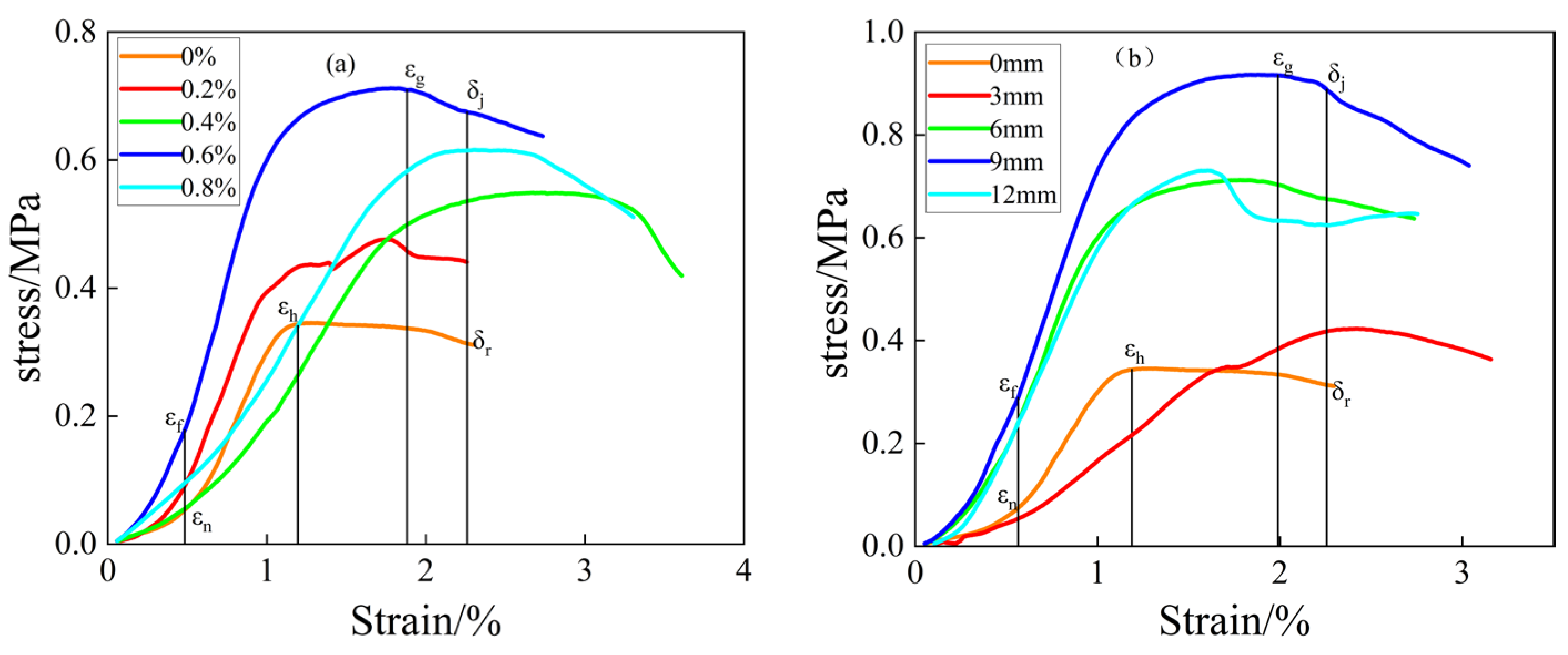
3.3. Evolution of Deformation Properties of BFCTB Specimens

The mechanical property mechanisms affecting BFCTB are mainly compressive strength, peak strain, first crack strain, and ductile deformation [31]. Theoretically, the area of the load-displacement curve is a better way to characterize fibers than a single parameter [31,32]. In this research, the load–displacement curve is converted into a stress–strain curve. The first crack strain factor, E, is used as the crack strength estimation parameter, the peak strain factor, K, as the peak strength estimation parameter, and the post-peak ductility coefficient, R, as the ductility estimation parameter. This leads to the following Equation [33]:
E = ε f ε n , K = ε g ε h , R = δ j δ r
where ε f is the first crack strain of a specimen filled with basalt fibers, ε n is the first crack strain of the unadulterated fiber specimen; ε g is the peak strain for specimens filled with basalt fibers; ε h is the peak strain of the fiber doped specimen; δ j is the stress in a specimen filled with basalt fibers at a strain of 2.25%; δ r is the stress of the unadulterated fiber at a strain of 2.25%. E is the ratio of the two strains, a measure of the strength of the specimen for the first time the crack; the higher the value of E, the greater the strength; K is the ratio of the two peak strains; in order to compare the size of the peak strain under different fiber doping, the greater the value of K, the higher the strength of the specimen; R-value is the ratio of the two stresses, comparing the two and then the same stress under the uniaxial compressive strength; the higher the sample’s ductility is higher, the better the residual strength.
From Equation (1), E, K, and R can be obtained for different basalt fiber dosages and fiber lengths at a maintenance age of 3 days. From Table 4 and Figure 6, it can be seen that E and K gradually increase with the increase of basalt fiber content as well as fiber length, and they are positively correlated. When the fiber length was fixed at 6 mm, and the fiber doping was varied from 0% to 0.8%, the maximum values of E and K were reached at 0.6% fiber doping, which were 1.36 and 1.63, respectively. When the fiber doping was fixed at 0.6%, varying the fiber length from 0 mm to 12 mm, E and K reached their maximum values of 1.45 and 1.65, respectively, at a fiber length of 9 mm. However, basalt fiber content and fiber length have different effects on R. The maximum R-value is 2.19 when the fiber doping is 0.6%, and the maximum R-value is 2.77 when the fiber length is 9 mm. By comparing the two values, basalt fiber length has a higher effect on the values of E, K, and R than fiber content. As can be seen from Figure 6, when the fiber length is 9 mm, the growth rates of E, K, and R are 45%, 65%, and 177%, respectively, which are significantly higher than those of the unadulterated basalt fibers.
The optimum value of E and K is 0.6% fiber doping when the fiber length is 6 mm; the optimum fiber length is 9 mm when the fiber doping is 0.6%. Therefore, considering E, K, and R together, the fiber doping of 0.6% and fiber length of 9 mm can be selected as the admixture, at which time the best improvement effect on the specimen of the filled body is achieved.

4. Theory of Filling Body Damage and Energy Dissipation

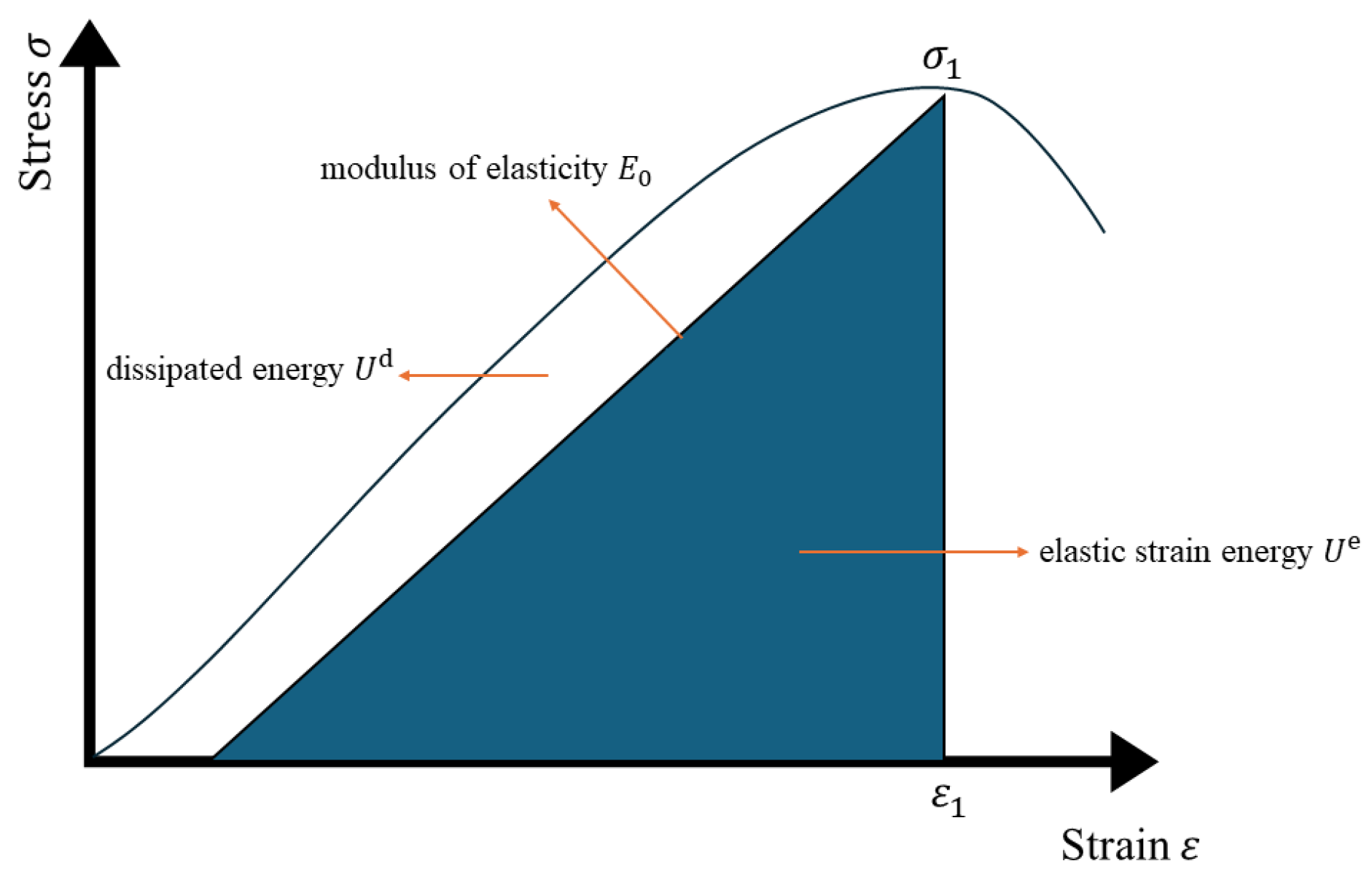
4.1. Principle of Energy Dissipation

Under uniaxial compression, the deformation damage of the filled body specimen is the result of energy accumulation and release. The total energy absorbed by the specimen is mainly converted into elastic strain energy and dissipated energy. Figure 7 shows the relationship between dissipated energy and elastic strain energy of the filling body under external loading.
Considering the destructive deformation of the filling body under external loading and assuming that there is no heat exchange with the outside world during this physical change, the following relation according to the first law of thermodynamics is obtained [34]:
U = U e + U d
where U   is the total work performed by the external force (i.e., the total strain energy). J ; U e   is the elastic strain energy. J ; U d   is the dissipation of strain energy for the formation of damage and plastic deformation within the filling body J .
In the principal stress space, the total strain energy and elastic strain energy in the filled body specimen cell can be expressed, respectively, as follows:
U = 0 ε 1 σ 1 d ε 1 + 0 ε 2 σ 2 d ε 2 + 0 ε 3 σ 3 d ε 3
U e = 1 2 σ 1 ε 1 e + 1 2 σ 2 ε 2 e + 1 2 σ 3 ε 3 e
ε i e = 1 E [ σ i μ i σ j + σ k ]
where σ i , σ j , σ k ( i , j , k = 1,2,3) is the principal stress in all directions; ε i , ε i e are the total and elastic strains in each principal stress direction; μ i , E i are the Poisson’s ratio and modulus of elasticity during the unloading phase, which can be replaced by μ 0 , E 0 for the elasticity phase. A related feasibility demonstration of the use of the initial modulus of elasticity instead of the unloaded modulus of elasticity for calculations can be found in the literature [35].
Due to the uniaxial loading being only axial stress work, circumferential stress and deformation are 0. According to Formulas (2) and (3), it can be determined that the unit volume of the filling body of each part of the strain energy calculation formula is as follows:
U = 0 ε 1 σ 1 d ε i
U e = 1 2 σ 1 ε 1 = 1 2 E u σ 1 2
The initial modulus of elasticity E 0 is used for the calculation instead, then Equation (7) can be rewritten as
U e 1 2 E 0 σ 1 2
Therefore, combining Equations (2), (6), and (8), it can be concluded that the dissipated energy during the loading process can be calculated using Equation (9):
U d = U U e = 0 ε 1 σ 1 d ε i 1 2 E 0 σ 1 2

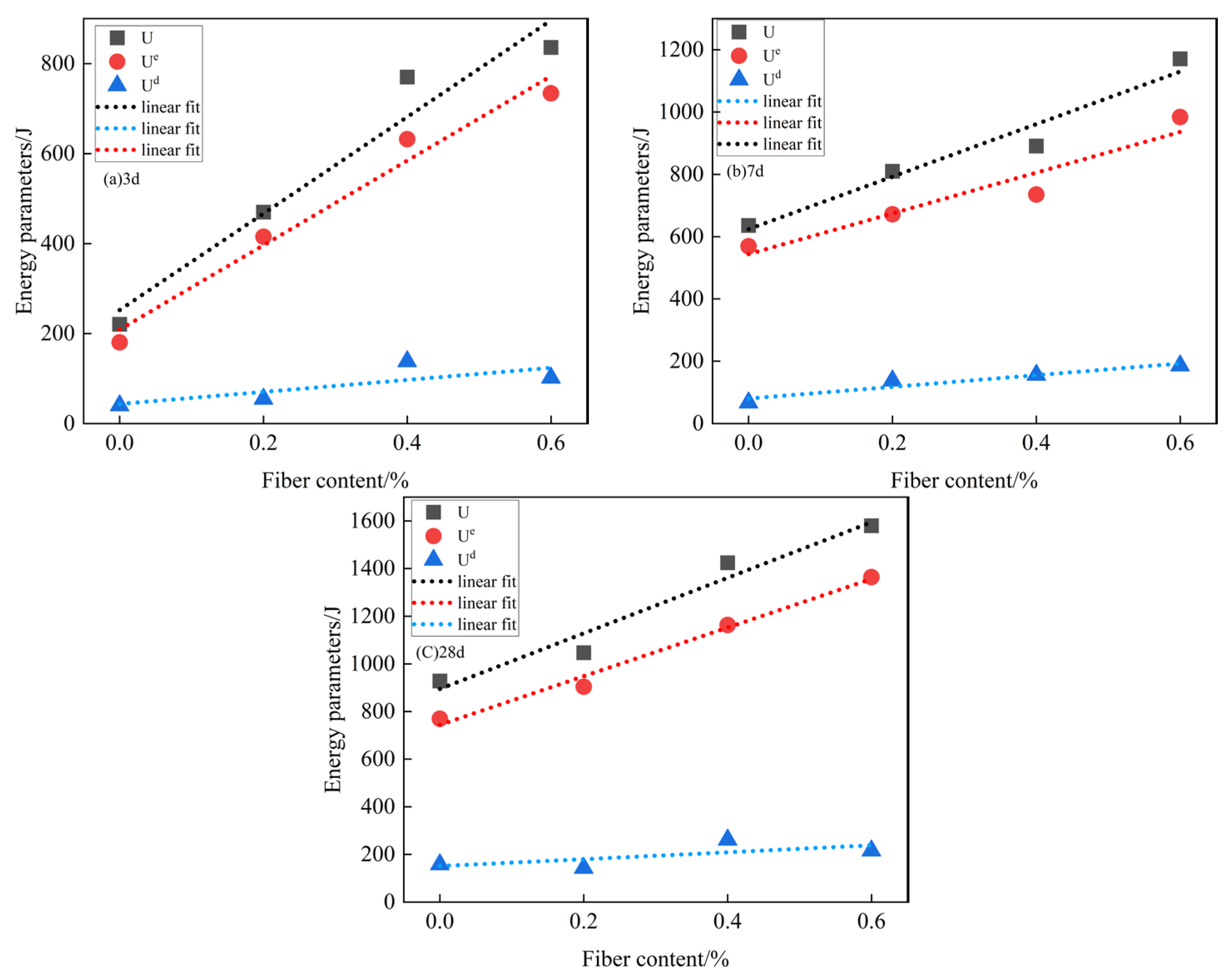
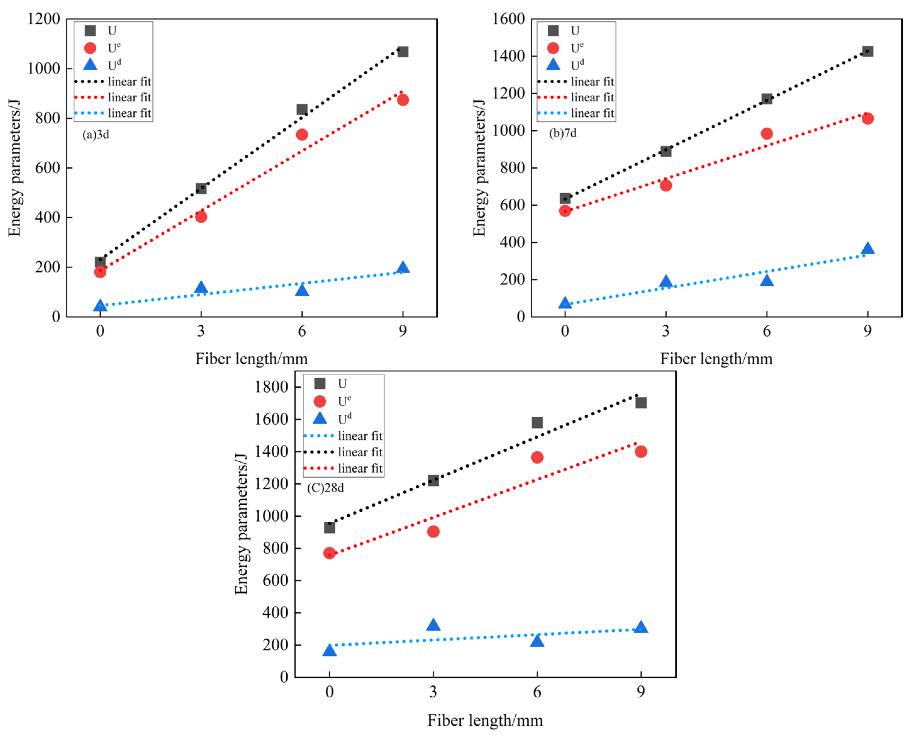
4.2. Characterization of the Variation of Energy Parameters of the Specimen

In order to reveal the energy storage of the tailing sand cemented filler under the influence of different factors, the total strain energy, elastic strain energy, and dissipation energy of the basalt-doped tailing sand cemented filler specimens at the peak stress point are summarized in Table 5 and Table 6. Table 5 shows the peak point energy parameters of the filled body specimens at different ages with different basalt fiber dosages; Table 6 shows the point-of-peak energy parameters of the filled body specimens at different ages for different basalt fiber lengths.
As can be seen from Table 5, when the fiber length is unchanged and the basalt fiber doping is 0–0.6%, with the increase of fiber doping, the total strain energy, elastic strain energy, and dissipation energy of the filled body specimen at the peak stress show an increasing trend, and they all reach the maximum value when the fiber doping is 0.6%, which indicates that fiber doping in this range can improve the energy storage capacity of the filled body specimen, which is macroscopically manifested in the increase of its compressive strength. And when the fiber doping continued to increase to 0.8%, the elastic strain energy of the BFCTB specimens at the peak stress point showed a tendency to decrease, which was macroscopically manifested as a decrease in the specimen load carrying capacity. Meanwhile, the energy storage limit (elastic strain energy at the peak point) of BFCTB specimens increased by 67.8%, 77.14%, and 88.63% with the increase of fiber doping from 0% to 0.6% at the curing ages of 3, 7, and 28 d, respectively, indicating that the increase of fiber doping is conducive to the enhancement of the load carrying capacity of BFCTB with the increase of curing age. In addition, the dissipated energy of BFCTB specimens before peak stress also shows an increasing trend with the increase of fiber doping, indicating that more and more energy is consumed in the pre-peak deformation stage of the filling body, which indirectly reflects that the increase of fiber doping improves the yield strength of BFCTB specimens.
As can be seen from Table 6, when the control basalt fiber doping is kept constant and the fiber length is 0 m–9 mm, with the growth of fiber length, the total strain energy, elastic strain energy and dissipation energy of the BFCTB specimens at the peak stress show an increasing trend, and all of them reach the maximum value when the fiber length is 9 mm, which indicates that the fiber length in this range can improve the energy storage capacity of the BFCTB specimens. This indicates that the fiber length in this range can increase the energy storage capacity of BFCTB specimens, which is macroscopically reflected in the increase of its compressive strength. And when the fiber length continues to increase to 12 mm, the elastic strain energy of the specimen out of the peak stress point shows a tendency to decrease, which is macroscopically manifested as a decrease in the load-bearing capacity of the specimen. Meanwhile, the elastic strain energy of the BFCTB specimens increased by 81.8%, 87.2%, and 116% with the increase of fiber length from 0 mm to 9 mm at the curing ages of 3, 7, and 28 d, respectively, indicating that the increase of fiber length is conducive to the improvement of the load-bearing capacity of the BFCTB specimens with the increase of the curing age. In addition, the dissipated energy of BFCTB specimens before the peak stress also shows an increasing trend with the growth of fiber length, indicating that more energy is consumed in the pre-peak deformation stage of the filling body, which indirectly reflects that the growth of fiber length can also improve the yield strength of BFCTB specimens.
Combined with the energy parameter data in Table 5 and Table 6, the total strain energy, elastic strain energy, and dissipation energy of the BFCTB specimens were fitted to the data as a function of the variation rule of fiber doping and fiber length, which are shown in Figure 8 and Figure 9. As can be seen from Figure 8, when the fiber doping is 0%-0.6%, the total strain energy, elastic strain energy, and dissipation energy of the BFCTB specimen basically follow the law of increasing primary function with the increase of fiber doping, which indicates that the increase of fiber doping can improve the specimen’s energy storage capacity, and macroscopically manifested as the linear elastic deformation stage can be extended to a higher level, which makes the specimen’s load carrying capacity increase with the increase of fiber doping. The load carrying capacity of the specimen increases with the increase of fiber doping. Figure 9 shows that when the fiber length is 0 mm-9 mm, the total strain energy, elastic strain energy, and dissipation energy of the BFCTB specimen basically follow the law of increasing primary function with the growth of the fiber length, which indicates that the growth of the fiber length also improves the energy storage capacity of the specimen, which is macroscopically embodied in the uniaxial compressive strength of the specimen when the increase in the fiber length is improved.

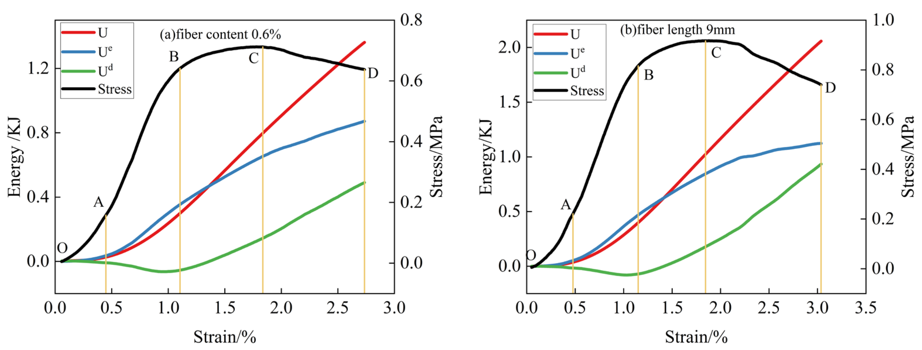
4.3. Evolutionary Law of Energy Distribution for Deformation Damage of BFCTB Specimens under Uniaxial Compression

According to the results of comparative analysis, the curing time of 3 d and 28 d, a fiber amount of 0.6% and 0, and lengths of 6 mm and 9 mm are listed as examples to reveal the energy evolution law of deformation damage of the specimens under uniaxial compression. The test results reveal the energy evolution characteristics of specimens under compression damage under the conditions of fiber content, fiber length, and age of maintenance, and the results are shown in Figure 10.
As can be seen from Figure 10, under uniaxial compression, the energy value of BFCTB specimen deformation and damage in each stage of deformation and damage increases with the change of strain and shows a nonlinear growth, comparing and analyzing the trend of the energy parameter of BFCTB specimen with the change of strain, the specimen energy distribution evolution law can be obtained as follows:
(1)
Initial pore and pore compaction stage (OA). At this stage, the initial pores and cracks inside the filled specimen are gradually compacted, while the energy value inside the specimen is small, and most of the energy will be converted into dissipated energy. Through the table and with the increase of fiber doping to 0.6% and fiber length to 9 mm, the proportion of dissipated energy is decreasing. Therefore, the energy is dominated by dissipated energy, and the total energy is small in the initial compacting stage;
(2)
Linear elastic deformation stage (AB). Within this phase, most of the energy absorbed by the filled body specimen is stored as elastic strain energy. And it can be seen from the Figure that the elastic strain energy has an overall linear growth trend, while the dissipated energy inside the specimen at this moment is basically maintained in a constant state. The percentage of elastic strain energy of BFCTB specimens was 80.8%, 82.54%, 86.83%, and 90.4%, as the fiber doping increased from 0% to 0.6% when the age of curing was 3 d. The percentage of elastic strain energy of BFCTB specimens was 80.8%, 82.54%, 86.83%, and 90.4%. As the fiber length grows from 0 mm to 9 mm, the percentage of elastic strain energy of the BFCTB specimen is 78.65%, 84.38%, 87.26%, and 89.83%, respectively. Therefore, in this linear elastic deformation stage, the energy absorbed by the specimen will be stored in the form of elastic strain energy. However, the proportion of elastic strain energy does not reach 100%, indicating that the linear elastic deformation of the specimen is not a fully elastic deformation, and the BFCTB specimen still produces a certain amount of damage in this stage, and this part of the lost energy will be in the form of dissipated energy;
(3)
Yield damage stage (BC). At this stage, the elastic strain energy of the BFCTB specimen is increasing, but the slope is slowly decreasing, showing an up-convex trend. At this time, new cracks are generated inside the specimen, and the dissipation energy shows an increasing trend, but the proportion of elastic strain energy is still higher than the dissipation energy. Therefore, the energy absorbed by the BFCTB specimen is still stored in the form of elastic strain energy at this yield damage stage, but the dissipated energy shows an increasing trend at this time;
(4)
Post-peak destruction phase (CD). In this stage, the elastic strain energy of the BFCTB specimen shows a decreasing trend, while the slope of the dissipation energy increases, showing a growing trend BFCTB specimen in this stage of the stored elastic strain energy reaches the limit, the specimen is pressurized to produce a macroscopic main crack, and the energy is released with kinetic energy and friction energy, etc., and at the same time the dissipation energy grows rapidly to make the filling body specimen damage is aggravated, thus reducing the load carrying capacity and resistance to deformation damage.

5. Damage Modeling of Cemented Fill with Basalt Fiber-Doped Tailing Sand under Uniaxial Compression

5.1. Establishment of Damage Modeling for BFCTB Specimens under Uniaxial Compression

Considering the tailing sand cemented filler as an isotropic continuous medium, in the one-dimensional elastic case, the damage eigenstructure equation is established according to the Lemaitre strain equivalence principle [36] as follows:
σ = E ε 1 D
where σ is the effective stress of the tailing sand cemented filling body (MPa); E is the modulus of elasticity of the cemented fill of the tailing sand (MPa); ε is the strain value of the cemented fill of the tailing sand; D is the tailing sand cemented filler damage variable. When D = 0 , the tailing sand cemented filler is in an undamaged state; when D = 1 , the tailings cemented fill is in a state of complete destruction.
Liu, Zhixiang, Zhao, Shuguo, and others [37,38] corrected the damage model of ordinary tailing sand cemented filling, but the results were unsatisfactory. Zhao Kang et al. [5] introduced the correction coefficient α into the damage model, which is more suitable for fiber-doped fillers. Since the fiber-doped filling body still has residual strength in the post-peak damage stage and has not completely lost its load-bearing capacity, it is necessary to study its post-peak strength characteristics and the post-peak load-bearing characteristics of the fiber-doped tailing sand cemented filling body is the basis for determining its filling strength. Therefore, a damage correction factor is introduced β 0 < β 1 to characterize the post-peak strength properties. Based on this, the damage eigenstructure equation is established as follows:
σ = σ 1 β D = E ε 1 β D
where σ is the effective stress of the tailing sand cemented filling body (MPa); β is the modified damage factor.
It is assumed that the micrometric damage of the filling body material obeys a Weibull distribution with probability density P F is expressed as follows:
P F = m F 0 F F 0 m 1 exp F F 0 m
where m , F 0 are parameterized variables of the Weibull distribution; F is the amount of strength distribution of the microelement body of the filling body.
Assuming that the number of microelement areas of the cross-section of the filling body that have been destroyed under a certain level of loading is S D n , the damage variable D is defined as the ratio of the area of destroyed microelements to the total number of microelements S n .
D = S D n / S n
Then, the number of micro-elementary areas S n P D n d D n that have been destroyed in any interval is F , F + d F ; when the load is loaded F , then the number of microelement areas that have been destroyed is
S D n F = 0 F S n P D n d D n = S n 1 exp F F 0 m
The couplings (12) and (13), simplified, give the following:
D = S D n / S n = 1 exp F F 0 m
Equation (14) is derived from the damage eigenstructure equation combined with Weibull’s statistical theory, the F is the micrometameric intensity distribution variable. The F can be used as either stress or strain. F Taking different values of physical quantities will result in different damage principal models. Since the damages of fiber-doped fillers are the result of local tension and shear, the strain energy can better express the process of crack evolution in the specimens of tailing sand cemented fillers, even though F = ε . At this point, the damage evolution Equation is as follows:
D = 1 exp ε F 0 m
Bringing Equation (16) into Equation (11), it is obtained that
σ = E ε 1 β D = E ε 1 β 1 exp ε F 0 m
According to the geometric boundary conditions of the stress–strain curve of the cemented filling body with basalt tailings, it is obtained that
σ ε = 0 = 0 σ ε = ε 1 = σ 1
d σ d ε ε = ε 1 = 0 d σ d ε D = 0 = E
where ε 1 is the peak strain. σ 1 is the peak stress (MPa).
Finally, Equation (18) is brought into Equation (17), and the calculations are checked.
According to Liu, C.C. et al., order k = β 2 2 β + 1 + β σ 1 / ε 1 E β 2 β + β σ 1 / ε 1 E , unwinding the system of simultaneous equations m and F 0 :
m = k ln σ 1 ε 1 E + β 1 F 0 = m ε 1 m k 1 m
Bringing Equation (19) into Equations (16) and (17) yields
σ = ε E 1 β + β exp k m ε ε 1 m
D = 1 exp k m ε ε 1 m

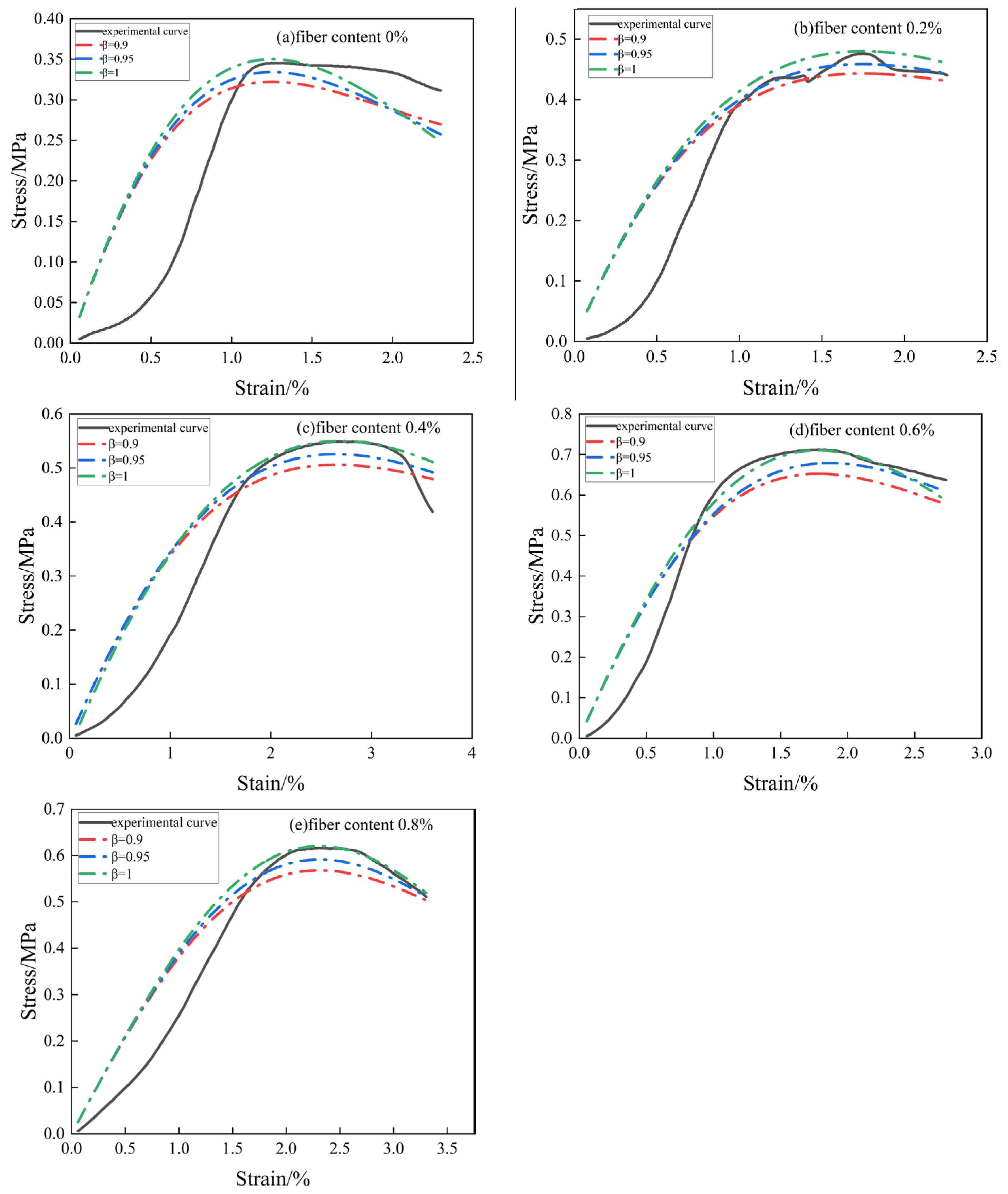
5.2. Theoretical Model Validation and Discussion

From the results of the indoor test, the stress–strain curve is plotted so as to obtain the peak strain and peak stress of the basalt-doped filling body, calculate the modulus of elasticity of each curve, and then introduce the damage correction coefficient β ; it can be derived from the stress–strain curve of the basalt-doped filling body model of the damage equation of the principal structure. Table 7 shows the model parameters of the damage constitutive equation of the basalt fiber-doped filler, and Table 8 and Table 9 show its damage constitutive equation and damage evolution Equation (with 3 d of maintenance and different basalt fiber dosage as an example).
Figure 11 shows the damage model curves of the filler with different contents β of basalt fibers by correcting the damage variables with three different damage parameters. The model curves at each modification factor are similar, while the modification damage factor mainly characterizes the residual strength properties of the filler after peaking. As can be seen from Figure 10, the tailing sand cemented filler mixed with basalt fibers did not lose its load-bearing capacity in the post-peak damage stage, and it was learned through observation that most of the filler specimens showed macroscopic main cracks only after the post-peak strains had reached a certain degree when the tests were carried out in the field, which indicated that the filler specimens still retained a certain amount of residual strength after the damage.
As can be seen from Figure 11, the difference between the theoretical and actual curves without basalt fibers is large, while the difference between the two curves with basalt fibers in the elasticity stage is small compared with the doping of fiber content of 0.6% in all stages of the most consistent, but all the curves in the peak as well as the peak after the better agreement. From the Figure, it can be seen that when the basalt fiber doping is in the range of 0% to 0.8%, and when the correction coefficient β = 1 , in the peak, the theoretical curve and the test curve are basically consistent, and with the reduction β from 1 to 0.9, the theoretical curve of the stress also decreases. However, at the post-peak stage, it can be seen from Figure 11a,d that the change of the theoretical curve is opposite to the peak, and the residual stress will increase with the β decrease of the residual stress, and the smaller it is, the larger the residual strength is. The curves do not differ much at the peak, and at the post-peak, the change of each theoretical curve increases with the increase of strain, indicating that the modified damage coefficient mainly affects the post-peak strength characteristics of the filling body and has less effect on the pre-peak.
In conclusion, the introduction of damage correction coefficients in the damage ontology model of basalt fiber doped tailing sand cemented filling body has a better effect, which is of guiding significance for the use of basalt fiber filling in mining airspace, and also has a particular reference value for engineering design and analysis. However, there are limitations, and studies have only been performed on different basalt fiber dosages and not on different fiber lengths.

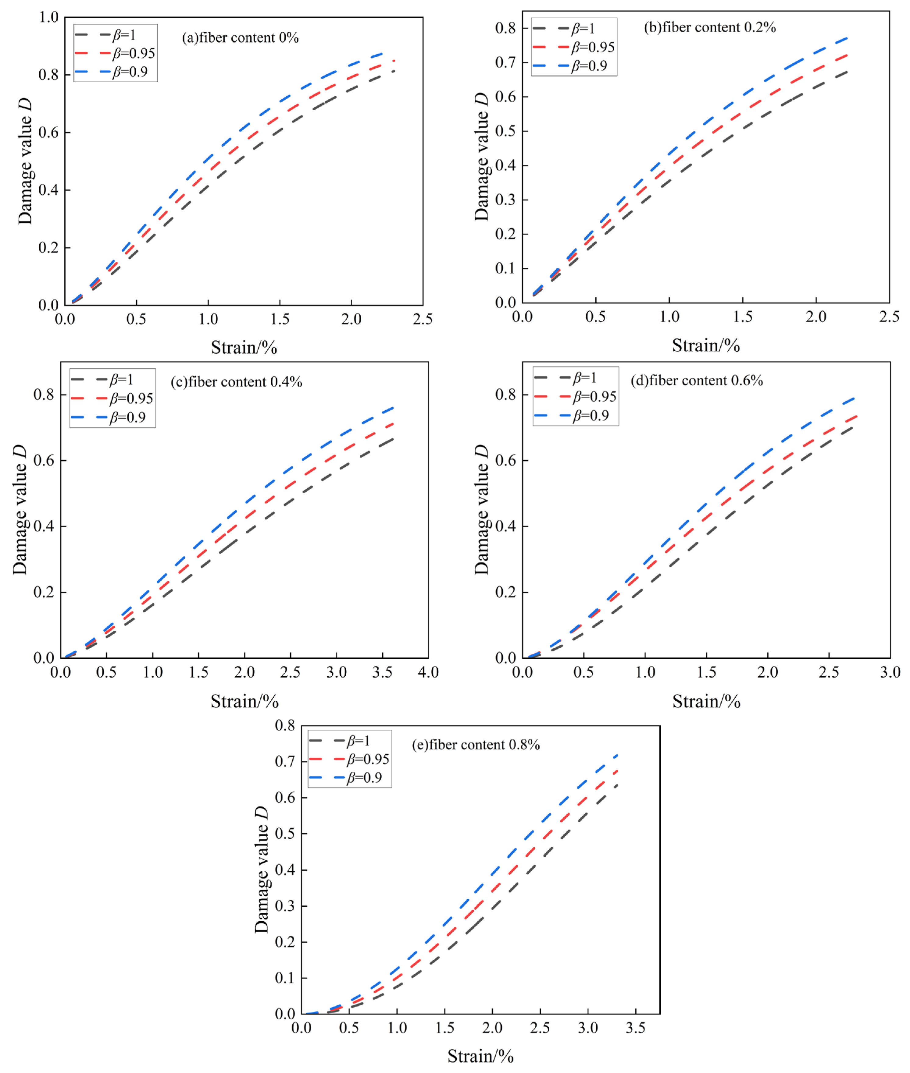
5.3. Compression Damage Evolution of BFCTB Specimens under Uniaxial Compression

Figure 12 shows the damage–strain curves of BFCTB specimens with different fiber dosages, from which the damage development pattern of tailing sand cemented filler with different dosages can be derived.
As can be seen from Figure 12, there is no obvious difference in the trend of the damage development curves with different damage correction coefficients, and the curves of the filler specimens without doped fibers show a “parabolic” increase, while the specimens with doped basalt fibers show an approximate “S”-type increase. The increase of the specimens with basalt fibers is similar to the “S” type. When the damage correction coefficient increases from 0.9 to 1, the overall growth rate of the damage curve gradually decreases, i.e., as the damage correction coefficient increases, the overall damage value of the filling body shows a smaller trend. After the peak strain is reached, the damage values of all specimens at the same strain satisfy D β = 0.9 > D β = 0.95 > D β = 1 , and combined with the Figure, it can be seen that the smaller, the larger the residual bearing capacity after the peak, and the larger the damage value. Therefore, in the actual working condition, different values can be chosen to construct the damage constitutive equations in order to adapt the tailing sand cemented filler with different fiber dosages. The overall damage of the filling body will grow with the axial strain, and the amount of damage gradually and slowly increases and tends to 1. When the strain value corresponds to the damage value infinitely tends to 1, it indicates that the filling body test is completely destroyed. The damage development curve of the doped fibers showed an “S”-type “slow—then rapid—then gentle” trend, indicating that the doping of basalt fibers can improve the macroscopic mechanical properties of the specimens of the filling body and improve its resistance to destructive deformation [5].
At the same time, combined with Figure 12, it is not difficult to see that at different basalt fiber doping, the damage value of the specimen with the increase of axial strain generally shows a nonlinear growth trend, indicating that the change of fiber doping does not affect the damage evolution process of the BFCTB specimen. The damage values of the BFCTB specimens increased the fastest when the fiber doping was 0%, and the damage values were larger compared to the specimens doped with a certain amount of basalt fibers, i.e., the extent of damage was greater. When the fiber doping is 0.2~0.8%, the growth rate of the damage value of the BFCTB specimen is slower than the damage value of the un-doped fiber-filled body, and the damage value is lower, which indicates that the addition of basalt fibers in the filled body can effectively inhibit the damage of the BFCTB specimen, and thus improve the load carrying capacity as well as the resistance to deformation damage of the filled body specimen. Meanwhile, the slope of the damage-strain curve in Figure 12 shows that the growth rate is slowing down with the increase of the fiber content. However, when the fiber doping exceeds 0.6%, the growth rate of the damage value of the specimen of the filled body with added basalt fibers is also accelerated with the increase of the fiber content. However, it is still slower than the growth rate of the damage value of the filled body with unadded fibers, which indicates that the excessive basalt fibers reduce the Basalt fibers and inhibit the effect of filling body damage. In addition, the axial strain value of the specimen without basalt fibers is significantly lower than that of the specimen with basalt fibers in the filling body to reach the same extreme damage value, which reflects that the specimen with basalt fibers has a better load-bearing capacity. The appropriate amount of basalt fibers can be uniformly dispersed inside the filled body specimen to form a certain cohesive force with the mortar [39], which improves the cracking resistance of the filled body specimen. Thus, the BFCTB specimen can undergo a large deformation in uniaxial compression before producing an overall damage.

5.4. Characteristics of Compressive Damage Evolution of BFCTB Specimens under Uniaxial Compression

The damage variable can accurately represent the process of damage evolution of the specimen material subjected to external loading and, at the same time, can reflect the macroscopic mechanical property changes of the specimen material subjected to external loading. Taking the maintenance age of 3 d, fiber doping of 0.6~0.8%, fiber length of 6 mm, and damage correction coefficient as an example, the damage value of the BFCTB specimen is plotted in relation to the stress value of the curve, as shown in Figure 13. It can be seen from Figure 13 that the damage evolution curves of the BFCTB specimens under uniaxial compression are basically nearly identical in morphology, which further indicates that the deformation damage of the BFCTB specimens is the same type of damage process. In addition, the damage evolution of BFCTB specimens under uniaxial compression can be divided into the following four stages by combining the characteristics of damage and stress values [40] as follows:
(1)
Initial damage stage (OA). At this stage, the damage value of the BFCTB specimen is almost zero, and the specimen is in the stage of pore compaction at this time. The microfractures and cracks inside the BFCTB specimen are compacted, and the slope of the damage evolution curve is zero;
(2)
Stable developmental stage of impairment (AB). The damage value of the BFCTB specimen at this stage gradually increases from 0, while the BFTF specimen is in the linear elastic deformation stage, which indicates that damage starts to occur inside the filled body specimen at the linear elastic stage. Moreover, with the increase of axial strain, the damage evolution curve of the BFCTB specimen shows a certain “concave” pattern;
(3)
The stage of accelerated damage growth (BC). The damage value of the BFCTB specimen increases rapidly during this phase, and the BFCTB specimen is in the yield damage phase. At this stage, the stress–strain curve of the BFCTB specimen shows a “convex”, while new cracks are created inside the specimen, leading to a rapid increase in the damage value;
(4)
Damage destruction phase (CD). The damage values of the BFCTB specimens within this phase show an overall linear increase when the filled body specimens are in the post-peak damage phase. When the damage value of the BFCTB specimen reached an extreme value, the overall damage of the filled body test occurred under uniaxial compression, and the specimen showed that it was also accompanied by the development of macroscopic main cracks and the dislodgement of part of the block. Therefore, when a whole BFCTB specimen is damaged by external load deformation, its damage evolution curve changes characteristics of “gentle-slow growth-fast growth-linear growth”.

6. Conclusions

In this paper, we investigated the uniaxial compressive force characteristics and damage law of tailing sand cemented filler doped with basalt fibers with an ash-to-sand ratio of 1:6 under different conditions (age of maintenance, fiber doping, and fiber length) and established and discussed the damage constitutive model of tailing sand cemented filler with different fibers doped, and the main conclusions obtained are as follows:
(1)
The stress–strain curves of the filled body specimens with basalt fibers added did not decrease rapidly after the external load exceeded the peak stress, indicating that the incorporation of basalt fibers improved the overall stability and resistance to deformation damage of the filled body specimens;
(2)
Uniaxial loading, with the increase of fiber doping and fiber length growth of the compressive strength and toughness index of the filling body (the first crack strain, peak strain, and residual stress), showed a trend of increasing and then decreasing, which indicates that the doping of an appropriate amount of basalt fibers can improve the mechanical properties of the filling body specimens, and the optimal value of fiber doping is 0.6%, and the optimal value of the fiber length is 9 mm;
(3)
Under uniaxial loading, with the increase of fiber doping, the total strain energy, elastic strain energy, and dissipation energy of basalt fiber-modified tailing sand cemented filling body at the peak stress showed a trend of increasing and then decreasing and reached the optimal fiber doping of 0.6%. The increase of fiber length on the energy of the filling body specimen is also so, and there is an optimal length of the same; the optimal length of the fiber is 9 mm. In the optimal range, the total strain energy, elastic strain energy, and dissipation energy of the filled body showed a linear growth pattern;
(4)
Under uniaxial loading, the fiber doping and fiber length do not significantly affect the change process of energy inside the BFCTB specimen and the conversion process. In the initial pore compaction stage, most of the energy absorbed by the filled body specimen is converted into dissipated energy. In the linear elastic deformation stage and yield stage, the energy inside the filling body is mainly stored in the form of elastic strain energy; in the post-peak damage stage, the stored elastic strain energy inside the filling body reaches the limit, and the dissipated energy grows rapidly, which accelerates the damage–destruction process of the BFTF specimen.
(5)
Based on the principle of Lemaitre strain equivalence and Weibull statistical theory to construct the damage constitutive equation, on the basis of the introduction of damage correction coefficient, and finally constructed the damage constitutive equation of basalt fiber doped tailing sand cemented filling body, found that the theoretical curve after the introduction of the damage correction coefficient with the experimental curve of a high degree of consistency, the engineering practice has a certain degree of significance and value of guidance and reference. On this basis, the damage evolution equation is derived, the characteristic law of damage evolution is analyzed, and the damage evolution process is divided into four stages: the initial damage stage (OA), the damage stable development stage (AB), the damage accelerated growth stage (BC), and the damage destruction stage (CD).

Author Contributions

Writing—original draft, R.C.; Writing—review & editing, Y.Z. All authors have read and agreed to the published version of the manuscript.

Funding

This research received no external funding.

Data Availability Statement

Due to confidentiality requirements, the data are not disclosed in this paper.

Conflicts of Interest

The authors declare no conflict of interest.

References

  1. Gao, M.Z.; Wang, M.Y.; Xie, J.; Gao, Y.N.; Deng, G.D.; Yang, B.G.; Wang, F.; Hao, H.C.; Xie, H.P. In situ perturbation dynamic behavior of deep coal rock. J. Coal Sci. 2020, 45, 2691–2703. [Google Scholar] [CrossRef]
  2. Benzaazoua, M.; Fall, M.; Belem, T. A contribution to under-standing the hardening process of cemented pastefill. Miner. Eng. 2004, 17, 141–152. [Google Scholar] [CrossRef]
  3. Mitchell, R.J.; Stone, D.M. Stability of reinforced cemented backfills. Can. Geotech. J. 1987, 24, 189–197. [Google Scholar] [CrossRef]
  4. Chen, X.; Shi, X.; Zhou, J.; Chen, Q.; Li, E.; Du, X. Compressive behaviour and microstructural properties of tailings polypropylene fiber-reinforced cemented paste backfill. Constr. Build. Mater. 2018, 190, 211–221. [Google Scholar] [CrossRef]
  5. Zhao, K.; Song, Y.; Yu, X.; Zhou, Y.; Yan, Y.; Wang, J. Early mechanical properties and damage modeling of tailing sand cemented fill under different fiber effects. J. Rock Mech. Eng. 2022, 41, 282–291. [Google Scholar]
  6. Hou, Y.; Yang, K.; Yin, S.; Yu, X.; Wang, L.; Yang, X. Enhancing the physical properties of cemented ultrafine tailings backfill (CUTB) with fiber and rice husk ash: Performance, mechanisms, and optimization. J. Mater. Res. Technol. 2024, 29, 837–848. [Google Scholar] [CrossRef]
  7. Yi, X.W.; Ma, G.W.; Fourie, A. Compressive behavior of fiber-reinforced cemented paste backfill. Geotext. Geomembr. 2015, 43, 207–215. [Google Scholar] [CrossRef]
  8. Cao, S.; Yilmaz, E.; Song, W. Fiber type effect on strength, toughness and microstructure of early age cemented tailings backfill. Constr. Build. Mater. 2019, 223, 44–54. [Google Scholar] [CrossRef]
  9. Wang, G.; Zhang, L.; Xu, M.; Liang, Z.; Ran, L. Study on the energy evolution mechanism of damage in non-through jointed rock mass under uniaxial compression. J. Geotech. Eng. 2019, 41, 639–647. [Google Scholar]
  10. Cheng, A.-P.; Dai, S.-Y.; Zhang, Y.-S.; Huang, S.-B.; Ye, Z.-Y. Study on the size effect of damage evolution in cemented fillings. J. Rock Mech. Eng. 2019, 38, 3053–3060. [Google Scholar]
  11. Zhou, Y.; Yan, Y.; Zhao, K.; Yu, X.; Song, Y.; Wang, J.; Suo, T. Study of the effect of loading modes on the acoustic emission fractal and damage characteristics of crmented paste backfill. Constr. Build. Mater. 2021, 277, 122311. [Google Scholar] [CrossRef]
  12. Liu, Z.X.; Ming, L.; Xiao, S.Y.; Guo, H.Q. Damage failure of cemented backfill and its reasonable match with rock mass. Trans. Nonferrous Met. Soc. China 2015, 25, 954–959. [Google Scholar] [CrossRef]
  13. Liu, Z.; Li, X.; Dai, T.; Cao, P. Damage modeling of tailing sand cemented fill and matching analysis with rock body. Geotech. Mech. 2006, 27, 1442–1446. [Google Scholar]
  14. Hou, Y.; Yin, S.; Cao, Y.; Yang, S.; Zhang, M. Uniaxial compressive stress-strain relationship of tailing sand cemented filler and its damage constitutive model. Mater. Rep. 2022, 36, 179–186. [Google Scholar] [CrossRef]
  15. Zhao, K.; Yu, X.; Zhou, Y.; Wang, Q.; Wang, J.; Hao, J. Energy evolution of brittle granite under different loading rates. Int. J. Rock Mech. Min. Sci. 2020, 132, 104392. [Google Scholar] [CrossRef]
  16. Rajak, D.K.; Pagar, D.D.; Menezes, P.L.; Linul, E. Fiber-reinforced polymer composites: Manufacturing, properties, and applications. Polymers 2019, 11, 1667. [Google Scholar] [CrossRef]
  17. Fazlnia, A. Origin and magmatic evolution of the Quaternary syn-collision alkali basalts and related rocks from Salmas, northwestern Iran. Lithos 2019, 344, 297–310. [Google Scholar] [CrossRef]
  18. Chen, J.; Gu, Y.; Yang, Z.; Wang, S. Effects of high temperature treatment on the composition and tensile properties of several basalt fibers. Mater. Eng. 2017, 45, 61–66. [Google Scholar]
  19. Xiao, J.Z.; Han, N.; Li, Y.; Zhang, Z.; Shah, S.P. Review of Recent Developments in Cement Composites Reinforced with Fibers and Nanomaterials. Front. Struct. Civ. Eng. 2021, 15, 1–19. [Google Scholar] [CrossRef]
  20. Yan, L.; Chu, F.L.; Tuo, W.Y.; Zhao, X.B.; Wang, Y.; Zhang, P.Q.; Gao, Y.B. Review of Research on Basalt Fibers and Basalt Fiber Reinforced Composites in China(I):Physicochemical and Mechanical Properties. Polym. Polym. Compos. 2021, 29, 1612–1624. [Google Scholar] [CrossRef]
  21. Ayub, T.; Shafiq, N.; Fadhil Nuruddin, M.; Ullah Khan, S. Mechanical properties of high-strength concrete reinforced with PVA and basalt fibers. In InCIEC 2013: Proceedings of the International Civil and Infrastructure Engineering Conference 2013, Kuching, Malaysia, 22–25 September 2013; Springer: Singapore, 2014. [Google Scholar]
  22. Borhan, T.M.; Bailey, C.G. Structural behaviour of basalt fiber reinforced glass concrete slabs. Mater. Struct. 2014, 47, 77–87. [Google Scholar] [CrossRef]
  23. Shaikh, F.; Haque, S. Behaviour of carbon and basalt fibers reinforced fly ash geopolymer at elevated temperatures. Int. J. Concr. Struct. Mater. 2018, 12, 35. [Google Scholar] [CrossRef]
  24. Sateshkumar, S.K.; Awoyera, P.O.; Kandasamy, T.; Nagaraj, S.; Murugesan, P.; Ponnusamy, B. Impact resistance of high strength chopped basalt fiber-reinforced concrete. Rev. Constr. J. Constr. 2018, 17, 240–249. [Google Scholar]
  25. Chin, S.C.; Shaaban, I.G.; Rizzuto, J.P.; Khan, S.U.; Mohamed, D.; Roslan, N.I.M.; Aziz, A.A. Predictive models for mechanical properties of hybrid fibers reinforced concrete containing bamboo and basalt fibers. Structures 2024, 61, 106093. [Google Scholar] [CrossRef]
  26. Yang, X.; Hou, Y.; Yin, S. Mechanical properties and energy distribution evolution characteristics of fiber-reinforced cemented filler with sulfur-containing tailings. J. Cent. South Univ. (Nat. Sci. Ed.) 2022, 53, 4435–4448. [Google Scholar]
  27. Yin, S.; Cao, Y.; Wu, A. Mechanical and flow properties of glass fiber reinforced cemented filler with sulfur-containing tailings. Mater. Her. 2023, 37, 246–252. [Google Scholar]
  28. Wu, A.; Wang, J.; Peng, N. Effect of grain composition on coarse aggregate filling slurry segregation. J. Cent. South Univ. (Sci. Technol.) 2016, 47, 3201–3207. [Google Scholar]
  29. Xue, X.; Gu, Y.; Zhang, X.; Wu, S.; Sun, P.; Cui, J.; Wang, X. Mechanical behavior and microscopic mechanism of fiber reinforced coarse aggregate cemented backfill. Constr. Build. Mater. 2023, 366, 130093. [Google Scholar] [CrossRef]
  30. Ardanuy, M.; Claramunt, J.; Toledo, F.R.D. Cellulosic fiber reinforced cement-based composites: A review of recent research. Constr. Build. Mater. 2015, 79, 115–128. [Google Scholar] [CrossRef]
  31. Sukontasukkul, P.; Pongsopha, P.; Chindaprasirt, P.; Songpiriyakij, S. Flexural performance and toughness of hybrid steel and polypropylene fiber reinforced geopolymer. Constr. Build. Mater. 2018, 161, 37–44. [Google Scholar] [CrossRef]
  32. Xu, F.; Deng, X.; Peng, C.; Zhu, J.; Chen, J. Mix design and flexural toughness of PVA fiber reinforced fly ash-geopolymer composites. Constr. Build. Mater. 2017, 150, 179–189. [Google Scholar] [CrossRef]
  33. Yan, R.F.; Liu, J.M.; Yin, S.H.; Zou, L.; Kou, Y.Y.; Zhang, P.Q. Effect of polypropylene fiber and coarse aggregate on the ductility and fluidity of cemented tailings backfill. J. Cent. South Univ. 2022, 29, 515–527. [Google Scholar] [CrossRef]
  34. Peng, R.; Xie, H.; Ju, Y. Analysis of energy dissipation and damage evolution during sandstone stretching. J. Rock Mech. Eng. 2007, 26, 2526. [Google Scholar]
  35. Xie, H.; Ju, Y.; Li, L. Rock strength and overall damage criterion based on the principle of energy dissipation and release. J. Rock Mech. Eng. 2005, 24, 3003–3010. [Google Scholar]
  36. Lemaitre, J. How to use damage mechanics. Nucl. Eng. Des. 1984, 80, 233–245. [Google Scholar] [CrossRef]
  37. Liu, Z.; Liu, Q.; Dang, W. Soft-hardening constitutive model of damage in tailing sand cemented fill. J. Shandong Univ. Sci. Technol. (Nat. Sci. Ed.) 2012, 31, 36–41. [Google Scholar] [CrossRef]
  38. Zhao, S.; Su, D.; Wu, W.; Zhang, Y. Uniaxial compression damage modeling of filling body based on Weibull distribution. China Min. Ind. 2017, 26, 106–111. [Google Scholar]
  39. Xu, W.; Du, J.; Song, W.; Chen, H. Experiment on the mechanism of consolidating backfill body of extra-fine grain unclassified tailings and cementitious materials. Rock Soil Mech. 2013, 34, 2295–2302. [Google Scholar]
  40. Hou, Y.; Yin, S.; Cao, Y.; Dai, C. Damage characteristics and energy dissipation analysis of tailing sand cemented fill under uniaxial compression with different maintenance ages. J. Cent. South Univ. (Nat. Sci. Ed.) 2020, 51, 1955–1965. [Google Scholar]
Figure 1. Particle size distribution of tailings.
Buildings 14 01851 g001
Figure 2. Sample preparation and compression process.
Buildings 14 01851 g002
Figure 3. Stress–strain curves of BFCTB specimens under uniaxial compression with different fiber contents and ages.
Buildings 14 01851 g003aBuildings 14 01851 g003b
Figure 4. Stress–strain curves of BFCTB specimens under uniaxial compression with different fiber lengths and ages.
Buildings 14 01851 g004
Figure 5. Relationship between compressive strength of cemented filler with basalt fiber doped tailing sand and fiber dosage (a) and fiber length (b).
Buildings 14 01851 g005
Figure 6. Stress–strain curve of BFCTB specimen under uniaxial compression: (a) fiber content; (b) fiber length.
Buildings 14 01851 g006
Figure 7. Relation between dissipated energy and elastic strain energy in a stress–strain curve.
Buildings 14 01851 g007
Figure 8. Energy parameters of BFCTB specimens under uniaxial compression versus fiber content.
Buildings 14 01851 g008
Figure 9. Energy parameters of BFCTB specimens under uniaxial compression versus fiber length.
Buildings 14 01851 g009
Figure 10. Energy evolution curves of BFCTB specimens damaged by compression under uniaxial compression.
Buildings 14 01851 g010
Figure 11. Test and theoretical curves of BFCTB specimens under uniaxial compression.
Buildings 14 01851 g011
Figure 12. Damage–strain curve of BFCTB specimen under uniaxial compression.
Buildings 14 01851 g012
Figure 13. Variation curve of damage value and stress value of BFCTB specimens under uniaxial compression.
Buildings 14 01851 g013
Table 1. Chemical composition of cement and tailing sand (mass fraction).
MakingsSiO2CaoFe2O3MgOAl2O3TiOK2OMnOOther
Tailings39.3123.3414.268.344.060.390.350.13.32
Clinker30.3647.653.172.5012.300.501.040.132.21
Table 2. Physical parameters of basalt fiber.
Fiber TypeTensile Strength/MPaElastic Modulus/GPaElongation/%Melting Point/°CAbsorbent
/%
Proportion
/(g/cm3)
Diameter
/μm
BF3000–350090–1103.21600<0.12.8–3.317
Table 3. Experimental design scheme.
SampleMass Concentration%Cement-Sand RatioTailingsFiber Length/mmFiber
Content/%
A072%1:6T100
A172%1:6T13 mm0.6%
A272%1:6T16 mm0.6%
A372%1:6T19 mm0.6%
A472%1:6T112 mm0.6%
B172%1:6T16 mm0.2%
B272%1:6T16 mm0.4%
B372%1:6T16 mm0.6%
B472%1:6T16 mm0.8%
Table 4. First crack strain, peak strain, and stress of strain 2.25% of 3 d cured BFCTB samples.
Influence FactorGroupsStrain of the First Crack/%EStrain of Peak Strength/%KStress of Strain 2.25%/MPaR
00.4011.210.311
0.20.421.051.721.420.441.42
Fiber content/%0.40.481.21.871.560.541.74
0.60.551.361.951.630.682.19
0.80.531.331.861.550.611.97
00.4011.210.311
30.431.081.701.420.421.35
Fiber length/mm60.551.361.951.630.682.19
90.581.451.981.650.862.77
120.511.281.881.570.632.03
Table 5. Peak point energy parameters of BFCTB under uniaxial compression with different fiber content.
Age of Conservation/dFiber Length/mmFiber Content/% U / J U e / J U d / J U e / U U d / U
00220.5180.440.181.8%18.2%
60.2470415.254.888.4%11.6%
360.4770631.9138.182.06%17.94%
60.6835.7734101.787.83%12.17%
60.8760616.1143.981.07%18.93%
00636.32569.466.9289.48%10.52%
60.2809.77672137.7782.99%17.01%
760.489173515682.49%17.51%
60.6117198418784.03%15.97%
60.8965.1858.6106.588.96%11.04%
0092877015882.97%17.03%
60.2104790414386.34%13.66%
2860.41424.51163261.581.64%18.36%
60.61579.51364215.586.36%13.64%
60.812431090.415387.69%12.31%
Table 6. Peak point energy parameters of BFCTB under uniaxial compression with different fiber lengths.
Age of Conservation/dFiber Length/mmFiber Content/% U / J U e / J U d / J U e / U U d / U
00220.5180.440.181.8%18.2%
30.651740311477.95%22.05%
360.6835.7734101.787.83%12.17%
90.6106887419481.84%18.16%
120.678463015480.36%19.64%
00636.32569.466.9289.48%10.52%
30.6888.8705183.879.32%20.68%
760.6117198418784.03%15.97%
90.61425.91065360.974.69%25.31%
120.6943.2810133.285.9%14.1%
0092877015882.97%17.03%
30.6122090431674.1%25.9%
2860.61579.51364215.586.36%13.64%
90.61702.51400302.582.24%17.76%
120.614341090.434476.01%23.99%
Table 7. Parameters for solving the damage constitutive model of the basalt-doped fiber-filled body.
Fiber Content/%Peak Stress/MPaPeak Strain/10−2Modulus of Elasticity/MPa β k m
0.901.2891.342
00.351.25580.951.1211.338
111.373
0.901.3391.203
0.2%0.481.75640.951.141.174
111.18
0.901.2831.378
0.4%0.552.65420.951.1191.379
111.419
0.901.2531.522
0.6%0.711.78740.951.0401.454
111.618
0.901.2121.876
0.8%0.622.31430.951.0911.966
112.122
Table 8. Damage constitutive equations for basalt-doped fiber-filled body.
Fiber Content/% Damage Stress Equation σ
σ = ε E 0.1 + 0.9 exp 0.96 ε / 0.0125 1.342
0 σ = ε E 0.05 + 0.95 exp 0.838 ε / 0.0125 1.338
σ = ε E exp 0.728 ε / 0.0125 1.373
σ = ε E 0.1 + 0.9 exp 1.113 ε / 0.0175 1.203
0.2 σ = ε E 0.05 + 0.95 exp 0.971 ε / 0.0175 1.174
σ = ε E exp 0.847 ε / 0.0175 1.18
σ = ε E 0.1 + 0.9 exp 0.931 ε / 0.0265 1.378
0.4 σ = ε E 0.05 + 0.95 exp 0.811 ε / 0.0265 1.379
σ = ε E exp 0.705 ε / 0.0265 1.419
σ = ε E 0.1 + 0.9 exp 0.823 ε / 0.0178 1.522
0.6 σ = ε E 0.05 + 0.95 exp 0.715 ε / 0.0178 1.454
σ = ε E exp 0.618 ε / 0.0178 1.618
σ = ε E 0.1 + 0.9 exp 0.646 ε / 0.0231 1.876
0.8 σ = ε E 0.05 + 0.95 exp 0.555 ε / 0.0231 1.966
σ = ε E exp 0.471 ε / 0.0231 2.122
Table 9. Damage evolution equations for the basalt-doped fiber-filled body.
Fiber Content/%Damage Evolution Equation D
D = 1 exp 0.96 ε / 0.0125 1.342
0 D = 1 exp 0.838 ε / 0.0125 1.338
D = 1 exp 0.728 ε / 0.0125 1.373
D = 1 exp 1.113 ε / 0.0175 1.203
0.2 D = 1 exp 0.971 ε / 0.0175 1.174
D = 1 exp 0.847 ε / 0.0175 1.18
D = 1 exp 0.931 ε / 0.0265 1.378
0.4 D = 1 exp 0.811 ε / 0.0265 1.379
D = 1 exp 0.705 ε / 0.0265 1.419
D = 1 exp 0.823 ε / 0.0178 1.522
0.6 D = 1 exp 0.715 ε / 0.0178 1.454
D = 1 exp 0.618 ε / 0.0178 1.618
D = 1 exp 0.646 ε / 0.0231 1.876
0.8 D = 1 exp 0.555 ε / 0.0231 1.966
D = 1 exp 0.471 ε / 0.0231 2.122
Disclaimer/Publisher’s Note: The statements, opinions and data contained in all publications are solely those of the individual author(s) and contributor(s) and not of MDPI and/or the editor(s). MDPI and/or the editor(s) disclaim responsibility for any injury to people or property resulting from any ideas, methods, instructions or products referred to in the content.

