Article

Numerical Simulation Study on the Impact of Deep Foundation Pit Excavation on Adjacent Rail Transit Structures—A Case Study

1
School of Civil Engineering, Hubei Engineering University, Xiaogan 432000, China
2
Wuhan Municipal Engineering Design & Research Institute Co., Ltd., Wuhan 430023, China
3
China Railway Siyuan Survey and Design Group Co., Ltd., Wuhan 430063, China
*
Authors to whom correspondence should be addressed.
Buildings 2024, 14(6), 1853; https://doi.org/10.3390/buildings14061853
Submission received: 10 May 2024 / Revised: 12 June 2024 / Accepted: 17 June 2024 / Published: 19 June 2024
(This article belongs to the Section Building Structures)

Abstract

:
Excavation in foundation pits can result in serious issues for nearby tunnel structures like deformation, differential settlement, and seepage damage, which profoundly impact project timelines and potentially endanger life and property safety. Therefore, it is imperative to investigate these impacts before and after construction and to facilitate timely adjustments of construction measures and reinforcement where possible. In this study, a foundation pit construction project near a rail transit line is employed as a case to comprehensive study the impact of on-site deep foundation pit excavation on adjacent rail transit structures by numerical simulation. A three-dimensional finite-element model of the foundation pit based on site geological characteristics and construction procedures is established to study the excavation and maintenance processes. Through analysis of key parameters including soil deformation, displacement, shear force, and bending moment of the tunnel structures, the designed protective structure is found to have effectively mitigated soil deformation, ensuring the stability of the foundation pit. As excavation progresses, lateral soil deformation and vertical uplift gradually increase but remain within specified control values. During various excavation stages, the maximum displacement of the tunnel structure gradually increases, with the increase rates of maximum settlement being 29.09%, 20.51%, and 6.45%, respectively. This indicates a gradual enhancement of the stability of the tunnel structure. Additionally, excavation of the foundation pit has a significant impact on the bending moment distribution of the tunnel structure but does not affect the axial force and shear force of the tunnel structure. The findings of this study offer crucial scientific insights for evaluating the safety and stability of construction near tunnel structures.

1. Introduction

Urban rail transit, as a significant measure to alleviate urban congestion, has experienced rapid development worldwide in recent years [1,2]. By the end of 2022, 545 cities in 78 countries and regions had established urban rail transit systems, with a combined mileage exceeding 41,386.12 km [3]. Following the construction of these rail transit structures, an increasing number of excavation projects, such as high-rise building basements and underground commercial centers, have been carried out near the existing subway lines.
Excavation projects inevitably disrupt the original stress-field balance in the foundation soil, thereby adversely affecting existing rail transit structures [4,5]. The excavation and unloading of foundation pits not only induce deformation in tunnel segments but also generate additional internal forces and joint displacements in the tunnel [6]. Excessive tunnel deformation can lead to issues affecting structural safety, such as tunnel water leakage and localized concrete crushing [7]. For example, during deep excavation construction adjacent to the subway tunnel section, the lateral unloading of the soil due to the traction of anchor cables during pit excavation can result in tensile deformation at the crown of the tunnel. This can lead to extensive damage to tunnel segments, including significant block loss and joint leakage [8,9,10]. Moreover, during pit excavation adjacent to subway tunnel sections in soft clay layers, severe accidents may occur, including tunnel segment damage, cracking, and water leakage [11]. These incidents underscore the importance of analyzing and assessing the impact of pit excavation on existing rail transit structures to prevent casualties and to minimize economic losses.
Early studies primarily focused on the deformation and displacement of soil caused by pit excavation, aiming to preliminarily reveal the direct impact of pit excavation on the soil through field monitoring and theoretical analysis [12]. Field monitoring stands out as the most direct method to assess the influence of pit excavation on soil deformation and displacement. By continuously monitoring key parameters such as soil displacement, stress changes, and groundwater levels during excavation, real-time data can be obtained, providing crucial validation and a reference for subsequent theoretical analyses [13]. As early as 1969, Peck (1969) analyzed a large amount of field monitoring data and identified the general patterns of soil displacement induced by pit excavation [14]. Excavation of foundation pits can induce significant deformation and displacement of the soil [15]. This effect is not only influenced by the depth and rate of excavation but also by various factors such as soil type and the choice of support structures. However, existing theoretical frameworks, which maintain a constant average effective stress at each excavation stage, are inadequate for the excavation process of rigid-fracture clay in deep foundation pits [16]. Wang et al. conducted a comparative analysis of surface soil deformation monitoring data from excavations in various types of soft-soil foundation pits in Shanghai, Taipei, and Singapore. They concluded that the risk of soil displacement in soft-soil foundation pits is significant, with a maximum vertical displacement reaching up to 0.45% of the excavation depth [17]. Furthermore, Ng et al. [18] investigated the impact of excavation on soil deformation by considering and not considering the stiffness of unsaturated soil. Their analysis revealed that neglecting the stiffness of unsaturated soil significantly overestimates the surface settlement and base heave. Conversely, incorporating the stiffness of unsaturated soil leads to more accurate predictions.
As research advances, modern scholars have begun to focus on the influence of pit excavation on the shear forces and moments of rail transit structures. Research indicates that properly designed support systems can significantly reduce the lateral displacement of excavated soil and ground settlement in the surrounding area [19,20,21]. Pile-anchor systems are highly effective in controlling the deformation of large-scale excavations, while multi-level support systems can provide uniform support at different depths, and by optimizing the arrangement and timing of support layers, the overall soil deformation can be minimized [18,22]. Through numerical simulations and model experiments, comprehensive studies of key parameters such as soil deformation, stress distribution during pit excavation, displacement, shear forces, and moments of rail transit structures have been conducted [23,24,25]. For example, based on numerical simulations, Liao et al. found that subway stations adjacent to deep excavations experience rotational and shear effects, potentially leading to structural fatigue and reduced safety [26]. Meanwhile, Ayasrah et al. [27] found that tunneling induces additional axial forces and bending moments as well as increasing axial settlement and lateral deflection after establishing a series of numerical simulations and investigating many parameters, such as tunnel diameter and the distance between the pile and tunnel at different tunnel axes, in deep and shallow tunnels. These studies, including new measurement technologies [28], indicated the regular pattern; namely, that for tunnels at the excavation’s base, stress is minimal, with limited displacement observed at monitoring points [4,29,30]. These studies collectively contribute to establishing a theoretical foundation for understanding the impact of excavation on nearby rail transit structures; however, as for the graded excavation of large pits, research has been quite limited in the analysis of the overall performance of the pit.
These studies provide valuable insights into analyzing the stress deformation of rail transit structures caused by pit excavation. However, current research predominantly focuses on analyzing the effects of factors such as support structure stiffness, soil type, and groundwater level on rail transit structures. When it comes to the graded excavation of large pits, research should not be confined to the analysis of the overall performance of the pit. It is crucial to delve deeper into understanding the stress states of the soil at different depths and locations. The excavation of large-scale pits for staged construction may result in differential impacts on the soil at various depths and positions compared with the overall excavation, underscoring the importance of comprehensively understanding the stress deformation of rail transit structures in this complex scenario. Additionally, excavation depth, as a significant factor influencing the impact of pit excavation on rail transit structures, remains inadequately explored due to limitations in its on-site measurement and observation, and the safety concerns inherent to large-scale engineering projects. Thus, investigating the impact mechanism of staged excavation of large pits on the stress deformation of rail transit structures and studying the regularities of stress behavior of rail transit structures at different excavation depths are of significant importance.
Building upon the analysis of the current research status and the identified research gaps, this paper leverages the section from Jixian Station to Zhiyin Station as a critical segment of the subway Line 4 project. By integrating the geological characteristics of the project area and the actual construction procedures of pit excavation, a detailed three-dimensional finite-element analysis model has been developed. Through simulating the process of pit excavation, a detailed analysis of the deformation patterns of soil and the variations in key parameters such as displacement, shear forces, and moments of tunnel structures during different construction phases has been conducted. The challenge in studying such issues lies in accurately simulating complex geological conditions and construction environments, as well as effectively in assessing the safety and stability of tunnel structures during pit construction. The research findings of this paper not only provide crucial scientific foundations for evaluating the safety and stability of tunnel structures but also offer valuable references for the design and construction of similar engineering projects.

2. Project Overview

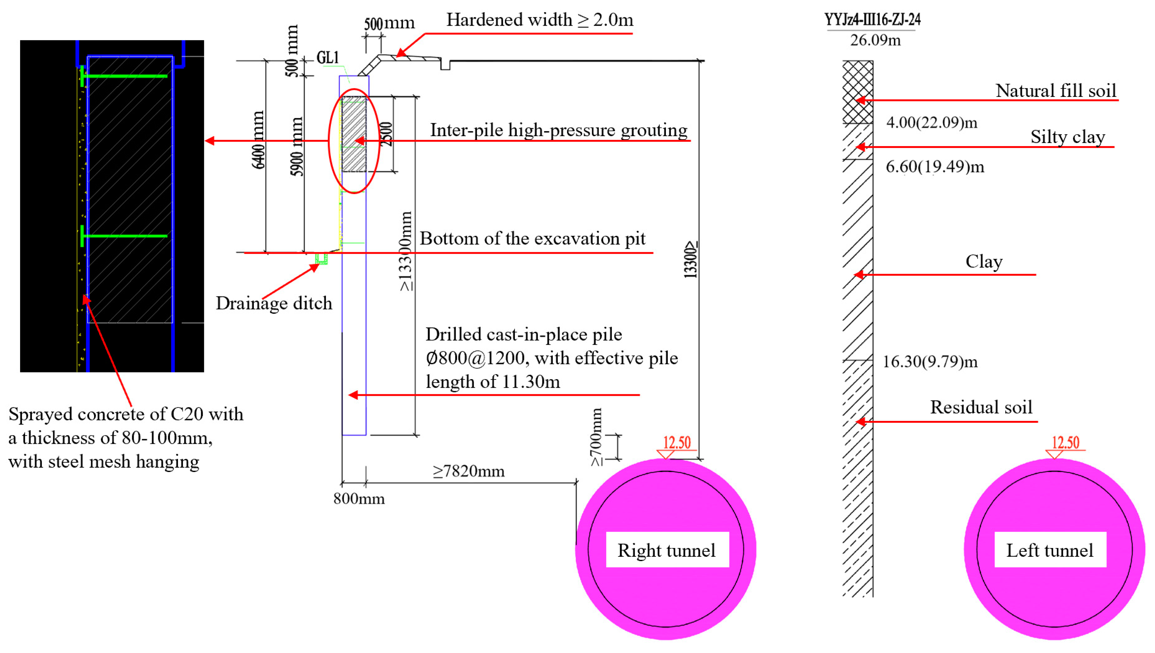
2.1. Foundation Pit Profile

The research case focuses on the DeGao Tower project, located at the intersection of Xintian Avenue and Jiezhi Road in Caidian District, Wuhan City, Hubei Province (Figure 1) in China, with elevations ranging from 25.53 m to 30.53 m. The project involves the construction of one 11-floor hotel (approximately 1021.2 m2), one 3-floor commercial building (1231.8 m2), and an overall basement spanning one level (approximately 5981.2 m2). The pit plan exhibits an irregular polygonal shape, with excavation depths ranging from 5.30 m to 7.20 m and a total perimeter of approximately 331.90 m. The total excavation area is approximately 6487.95 m2. On the north side of the pit excavation area, the distance to the existing subway Line 4, between Jixian station and Zhiyin station, where the right-side tunnel spans from stake DK11 + 207.86 (meaning that the location is 11 km plus 207.86 m from the starting point of the project) to DK11 + 278.98, and the left-side tunnel spans from stake DK11 + 210.80 to DK11 + 280.58, is relatively close, with a minimum clearance of 7.82 m. The excavation depth on the north side of the pit is approximately 6.2 m to 6.4 m, with a vertical distance from the subway tunnel structures ranging from approximately 6.9 m to 8.7 m. According to the relevant provisions of Article 50 of the Wuhan Rail Transit Management Regulations, the protection zone for rail transit projects under construction and in operation should be 450 m outside the outer edge of underground stations and tunnels and 10 m outside the outer edge of structures such as entrances, ventilation pavilions, substations, and the land area of vehicle bases. Therefore, the foundation pit project for this project is within the engineering safety protection zone (50 m) of Line 4 of the rail transit system. Thus, the construction of the foundation pit may pose a significant risk to the existing rail transit structure and its safe operation. Therefore, studying the impact mechanism of this pit excavation on nearby subway structures is representative and can provide a theoretical basis for safety control in similar construction projects.
The pit support utilizes a cantilever support system with a bored pile foundation, with slope reduction above the pile top and local corner bracing. Specifically, Φ800@1200 mm bored piles are employed near the subway, while φ800@1300 mm bored piles are used further away. The effective length of the support piles ranges from 11.30 m to 13.80 m, with a slope reduction height of 0 to 1.0 m and a slope ratio of 1:1.0. At the top of the support piles, crown beams are installed for connection, with specifications of 1.2 m × 0.8 m and 1.0 m × 0.8 m, using concrete grade C30. Slope surfaces between piles and the unloading platforms are protected using soil nail-and-wire mesh systems. The wire mesh consists of φ6.5 steel bars arranged in a U-shaped pattern with the spacing set at 1.5 m × 1.5 m. The slope surfaces are fully covered with 2 mm × 100 mm × 50 mm steel plate mesh, and the shotcrete grade is C20, with a thickness of 80 mm. For the section adjacent to the railway (MACDE segment), the effective length of the bored piles is 11.3 m. The surrounding loose soil layers of the piles are reinforced using Φ800 inter-pile jet grouting piles to prevent water and soil from flowing between the piles. At the corners of this section, the pit adopts reinforced bracing with concrete supports to enhance the structural strength and to reduce displacement and deformation during excavation. The plan and profile diagrams of the project’s subway Line 4 from Jixian Station to Zhiyin Station are illustrated in Figure 2 and Figure 3, respectively.

2.2. Engineering Geology and Hydrogeological Conditions

The proposed construction site is located between the elevations of 25.53 m and 30.53 m above ground level, which is characterized by the landform unit of the Yangtze River’s third-level terrace. The geological composition within the excavation depth of the pit is complex. The division of soil layers from top to bottom is as follows:
(1)
Quaternary Q4ml loessial fill;
(2)
Quaternary Q4dl + pl loamy clay of flood and slope deposits;
(3)
Quaternary Q4dl + pl loamy clay and loamy clay interbedded with crushed stones;
(4)
Quaternary Q4el residual soil;
(5)
Quaternary Q4el + dl residual-slope deposits;
(6)
Cretaceous to Lower Tertiary K-E calcareous siltstone and breccia.
The site of this project mainly contains three types of groundwater: perched water in the upper layer, fracture water in the bedrock, and karst fissure water. The perched water exists in the fill layer, with the water level and volume varying seasonally. The stable water level is buried at a depth of approximately 0.70 to 2.30 m. The fracture water in the bedrock and the karst fissure water exist in mudstone and soluble rock (breccia), respectively. They are primarily replenished and discharged through lateral flow; with a low water volume and an uneven distribution, they have negligible impact on the project.

3. 3D Finite-Element Model and Calculation Parameters

3.1. Design of the Excavation-Mode Land Calculation Parameters

This study utilizes the MIDAS/GTS NX 2022a software to establish a three-dimensional numerical model and to simulate the impact of pit excavation on the adjacent subway Line 4 tunnel. MIDAS GTS/NX is a commercially available finite-element analysis software widely used in geotechnical, civil, and mining engineering for analysis, testing, and design purposes. The software features various advanced modeling capabilities, enabling the high-precision modeling of complex projects, making it highly suitable for analyzing the impact of pit excavation on existing structures.
To ensure the accuracy of the results and to avoid a decrease in the numerical model resolution, it is recommended that the computational domain size not be considerable. Based on extensive engineering experience and Saint-Venant’s principle, the outer extension of the numerical model should be at least three times the depth of the pit during pit numerical calculations. In this study, the computational range of the numerical simulation is 150 m in length and 120 m in width, and the soil layer calculation depth is 45 m, which is approximately nine times the excavation depth. Since the area within 50 m outside the outer boundary of the subway is designated as the subway protection zone, the simulated excavation area should be more than 50 m from the subway boundary. After completion of the modeling process, the model consists of geological layers, existing rail transit shield tunnel segments, pit retaining structures (bored-pile walls), internal supports, and crown beams. The total number of mesh elements is 423,026, and the number of nodes is 74,109. The overall mesh division after modeling completion is shown in Figure 4a, and the positions of the excavation and subway lines are presented in Figure 4b. The geological layers are modeled using the modified Mohr-Coulomb constitutive model, while the pit retaining structures and shield tunnel segments are simulated using plate elements. The internal supports and crown beams are simulated using beam elements. All the structural elements are modeled using elastic constitutive models. The specific material parameters for the geological layers and structural parameters are detailed in Table 1 and Table 2, respectively, based on a comprehensive analysis of geological survey data and relevant engineering experience.
It is noteworthy that the retaining structure for the pit in this study is composed of bored-pile walls. Due to their similar load-bearing characteristics to underground diaphragm walls, the bored-pile wall retaining structure can be converted into an equivalent thickness to the diaphragm wall for calculation purposes, based on the principle of equal flexural stiffness between the two. The conversion formula is as follows:
1 12 ( D + t ) h 3 = 1 64 π D 4
h = 0.838 D 1 t D + t 3
where D represents the diameter of the support piles, t represents the net spacing between piles, and h represents the equivalent thickness of the converted diaphragm wall. In this study, the equivalent thickness of the retaining wall converted from the Φ800@1200 bored-pile wall is 573 mm. During the calculation process, the boundary of the excavation surface is set as a free constraint, while the sides of the model are constrained in the normal direction, and the bottom is fixed. As groundwater is present in (1) the layer of fill soil and (2) the layer of silty clay with silt, this water cannot be overlooked, even though although the water quantity is limited. Therefore, seepage simulation work was conducted during the modeling process.

3.2. Excavation Support Simulation

In real engineering, the soil strata are already in a stable state due to long-term self-weight stress. When simulating excavation in the foundation pit, the initial stress state of the foundation pit model needs to be simulated first. This involves balancing the initial stress field and zeroing the displacement field of the computational model. Additionally, this analysis primarily focuses on assessing the impact of the proposed foundation pit construction on the railway transit structure and the deformation of the pit support structure. Considering the incremental displacement caused by the pit excavation, it is necessary to zero out the initial stress field and displacement field caused by the construction of existing structures. The excavation simulation was divided into three stages, with the first and second stages having an excavation depth of 2 m, and the third stage having an excavation depth of 2.4 m. Based on the excavation stages of the foundation pit, eight construction procedures are delineated, as detailed in Table 3.

4. Results and Discussion

4.1. Deformation Analysis of Foundation Pit Support Structures during Excavation Stages

The horizontal displacement analysis for the retaining structure of the pit is essential for ensuring pit stability, predicting potential risks, optimizing design solutions, and guiding construction operations. Using the three-dimensional finite-element method to simulate the characteristics of the horizontal displacement of the retaining structure under layered excavation conditions, the calculation results are shown in Figure 5.
During the construction process of the retaining structure for the excavation, the structure begins to bear the lateral pressure from the soil. However, since the structure has just been installed and has not yet experienced the release of soil caused by subsequent excavation, the displacement is relatively small. Numerical calculation results indicate that the maximum displacement of the structure under the retaining construction condition is 2.53 mm. This suggests that at this stage, the retaining structure can effectively control soil deformation and maintain good stability. As the soil is excavated, the original stress equilibrium is disrupted, causing the soil to move into the excavation area and exert greater lateral pressure on the retaining structure. At this stage, the maximum displacement is 2.85 mm, which is slightly higher than that of the first condition, reflecting the influence of stress release on the retaining structure and the redistribution of soil during the excavation process. In the simulation of excavation stage 3, representing the second stage of excavation, as the excavation progresses, the effect of soil release becomes more pronounced, leading to further increases in the lateral pressure on the retaining structure. The maximum displacement is 2.62 mm, significantly higher than that of the second condition. This indicates that as the excavation deepens, the lateral pressure exerted on the retaining structure by the soil gradually increases, resulting in increased deformation. Excavation stage 3 simulates the final stage of excavation for the pit. At this point, the pit is nearing its design depth, and the soil release effect is most pronounced, resulting in the maximum lateral pressure on the retaining structure. The maximum displacement is 7.40 mm, the largest among the four conditions. This reflects that in the final stage of excavation, the lateral pressure exerted on the retaining structure by the soil is greatest, leading to the most significant deformation.
In summary, the numerical simulation analysis of the four conditions reveals that the retaining structure effectively maintains stability and that soil deformation is controlled during construction. With increasing excavation depth, the lateral pressure on the retaining structure gradually rises, resulting in increased deformation. However, displacement values consistently remain below the specified control limits, demonstrating the effectiveness of the design and construction measures.

4.2. Displacement and Deformation Analysis of the Excavation Pit after Excavation

The excavation stages for the foundation pit was numerically simulated to analyze the impact of different construction stages on soil deformation. Post-excavation, the deformation cloud map of the pit soil mass, as depicted in Figure 6, illustrates significant deformation primarily at the bottom of the pit, with a notable vertical displacement. Following the removal of the upper soil load, a distinct uplift is observed, particularly at the central location, with a maximum cumulative deformation of 22.55 mm. Additionally, due to the imposition of supporting structures, friction occurs between the diaphragm wall and the strata, resulting in compression of the soil near the excavation sidewalls. As the distance between the supporting structures and the ground surface increases, downward settlement of the surface soil gradually occurs, with a maximum cumulative settlement of 4.20 mm. Figure 6b illustrates that after the excavation of the pit, the horizontal displacement field distribution at the bottom of the pit is uneven. At the corners of the pit, the lower soil experiences stress concentration due to soil excavation, resulting in significant lateral soil pressure and horizontal displacement, with a maximum deformation of 9.88 mm. The horizontal displacement of the surrounding soil ranges from 0 to 1.65 mm, with the soil layer adjacent to the drilled pile reinforced with inter-pile jet-grouting piles showing minimal horizontal displacement, indicating the effective prevention of soil erosion. Moreover, as the distance between the supporting structure and the ground surface increases, there is a trend of increasing horizontal displacement followed by a decrease. At a distance of approximately 125 m from the edge of the pit, the horizontal displacement becomes negligible.
According to the relevant provisions of the local standard in Hubei Province “Technical Specifications for Foundation Pit Engineering” (DB 42/T159-2012) [31], the cumulative horizontal displacement and vertical settlement of the ground surface around the pit should not exceed 30 mm. For this project, both the horizontal and vertical displacements around the pit after excavation and support are less than the displacement control value. Therefore, the design and construction of this foundation pit meet the requirements of the foundation pit engineering specifications for Hubei Province.

4.3. Impact of Foundation Pit Construction on the Adjacent Tunnel Section

4.3.1. Tunnel Structure Deformation Analysis

The excavation of the foundation pit results in significant effects on the adjacent existing rail transit structure (double-track tunnel), leading to both horizontal and vertical displacements of the tunnel structure. Prior to the commencement of the foundation pit construction, the tunnel structure is subjected to the original stress field, resulting in minimal displacement. However, with the excavation of the foundation pit, there is a change in the stress field, causing the tunnel structure to experience stress release and redistribution, thereby initiating deformation.
(1)
Calculation Results of Horizontal Displacement in the Tunnel
The horizontal displacement cloud map of the tunnel structure during the construction process is shown in Figure 7. Different characteristics of the horizontal displacement are observed at various construction stages:
  • During the construction phase of the protective structure, the maximum displacement of the tunnel is 0.71 mm. This indicates that during the construction phase of the protective structure, the tunnel structure experiences some degree of influence, but this is relatively minor.
  • During the first stage of excavation, as the pit excavation commences, the stress release and changes in the stress field of the soil become more pronounced. The impact on the tunnel structure increases, with the maximum displacement reaching 1.96 mm. Compared with the construction phase of the protective structure, the first stage of excavation has a greater impact on the tunnel structure, suggesting that as excavation progresses, the displacement of the tunnel structure gradually increases.
  • During the second stage of excavation, as the pit continues to be excavated, the stress release and changes in the stress field of the soil further intensify. The displacement of the tunnel structure continues to increase, with the maximum displacement reaching 3.86 mm. Compared with the first stage of excavation, the second stage slightly increases the impact on the tunnel structure, albeit with a modest increase. This is attributed to the gradual reduction in the speed of the stress release and changes in the stress field as the excavation progresses deeper.
  • In the third stage of excavation, as the pit excavation approaches completion, the stress release and changes in the stress field of the soil reach their maximum. The displacement of the tunnel structure also reaches its maximum value of 6.08 mm. Compared with the second stage of excavation, the third stage significantly increases the impact on the tunnel structure, indicating that during the final stage of the pit excavation, the influence on the tunnel structure becomes most pronounced.
From the construction phase of the protective structure to the first stage of excavation, the maximum displacement of the tunnel structure increased by approximately 176.06%, indicating a significant impact of pit excavation on the tunnel structure during this stage. This is due to the early stages of excavation, where stress release and changes in the stress field of the soil layer are quite intense. The stress in the soil around the tunnel is rapidly released, especially near the excavation face, where the stress-release effect is most significant, resulting in considerable displacement of the tunnel structure. From the first stage of excavation to the second stage, the maximum displacement of the tunnel structure increased by approximately 96.94%, followed by a relatively small increase. This is because as the excavation progresses, the speed of the stress release and changes in the stress field gradually decreases, allowing the tunnel structure to adapt to the new stress state. From the second stage of excavation to the third stage, the maximum displacement of the tunnel structure increased by approximately 57.51%, followed by a larger decrease. This is because during the final stage of pit excavation, the stress release and changes in the stress field reach their maximum, resulting in significant displacement of the tunnel structure.
(2)
Calculation results of settlement in the tunnel
The calculation results of settlement in the tunnel are shown in Figure 8, with varying settlement values observed at different construction stages, which are detailed as follows:
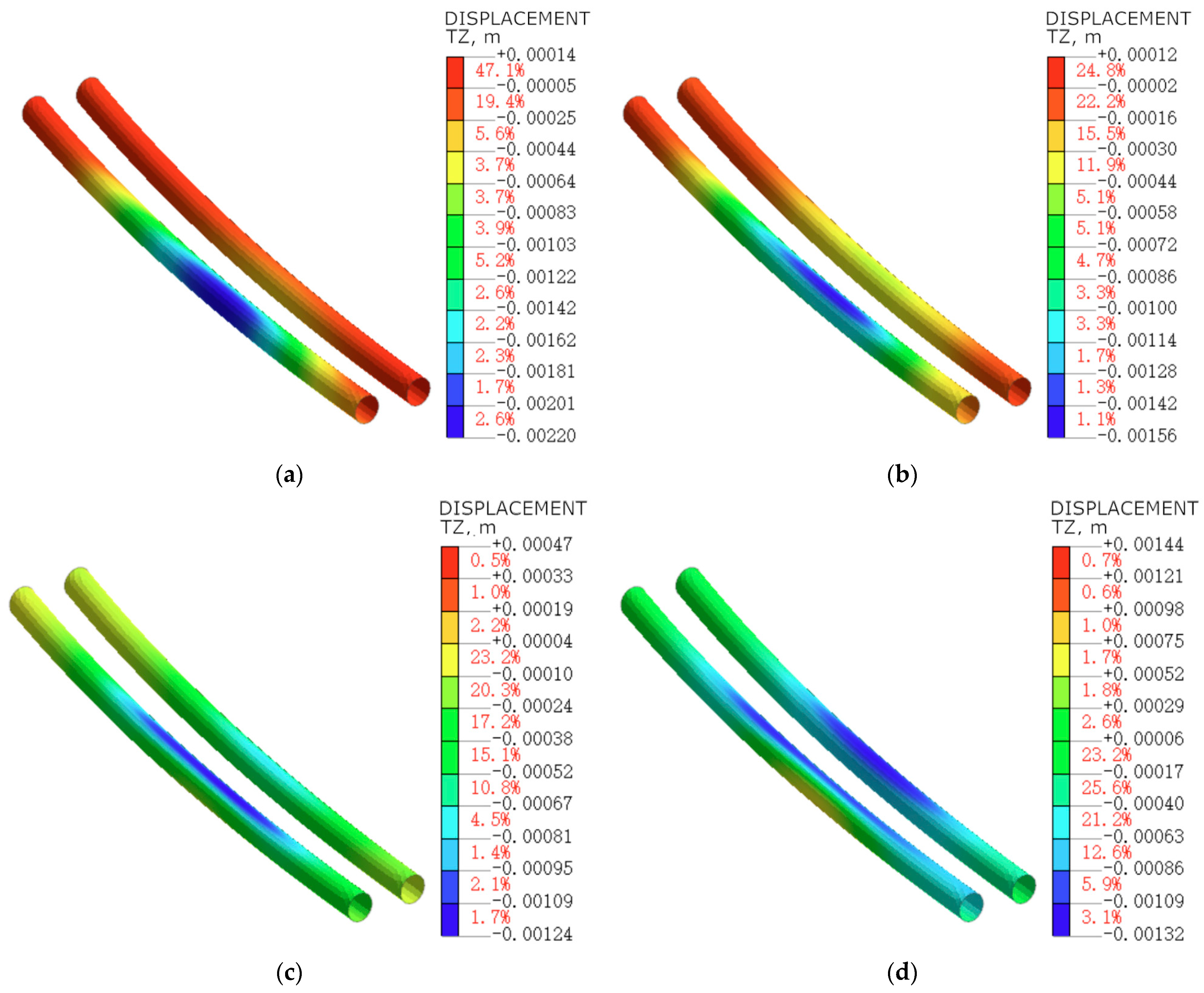
  • During the construction phase of the protective structure, the overall model exhibits a maximum settlement of −2.20 mm. This is because during the construction of the enclosure, the construction activities alter the stress distribution and bearing capacity of the soil layer. The overlying strata lose part of their self-supporting capacity, and the increased self-weight of the enclosure structure causes more load to be borne by the tunnel structure, resulting in significant settlement.
  • During the first stage of excavation, stress begins to release, and the stress field of the soil changes as the pit excavation progresses. The maximum settlement value during this stage is −1.56 mm, which is slightly smaller compared with the construction phase of the protective structure. This is due to the initial stage of excavation, where some stress is released, but at the same time, the effects of the support structure also begin to manifest, jointly influencing the displacement of the overall model.
  • During the second stage of excavation, the maximum settlement value during this stage is −1.24 mm, which further decreases compared with the previous stage. This indicates that as the excavation progresses deeper, the changes in stress release and the stress field of the soil gradually stabilize. Additionally, the role of the supporting structure becomes more pronounced, effectively controlling the displacement of the overall model.
  • During the third stage of excavation, the final maximum settlement value is −1.32 mm, similar to that of the second stage. This indicates that during the final stage of pit excavation, the displacement of the overall model has stabilized, and the impact of pit excavation on the existing rail transit structure gradually diminishes.
To further analyze the impact of pit construction on the section tunnel and to reveal the trend of settlement variation, the increase rates of the maximum settlement in the tunnel structure were calculated for different construction phases, from the construction phase of the protective structure to the third stage of excavation. The increase rates of the maximum settlement were found to be 29.09%, 20.51%, and 6.45%, respectively. This indicates that at different stages of pit excavation, the maximum settlement of the tunnel structure gradually decreases. As the excavation progresses deeper, the stability of the tunnel structure gradually increases.

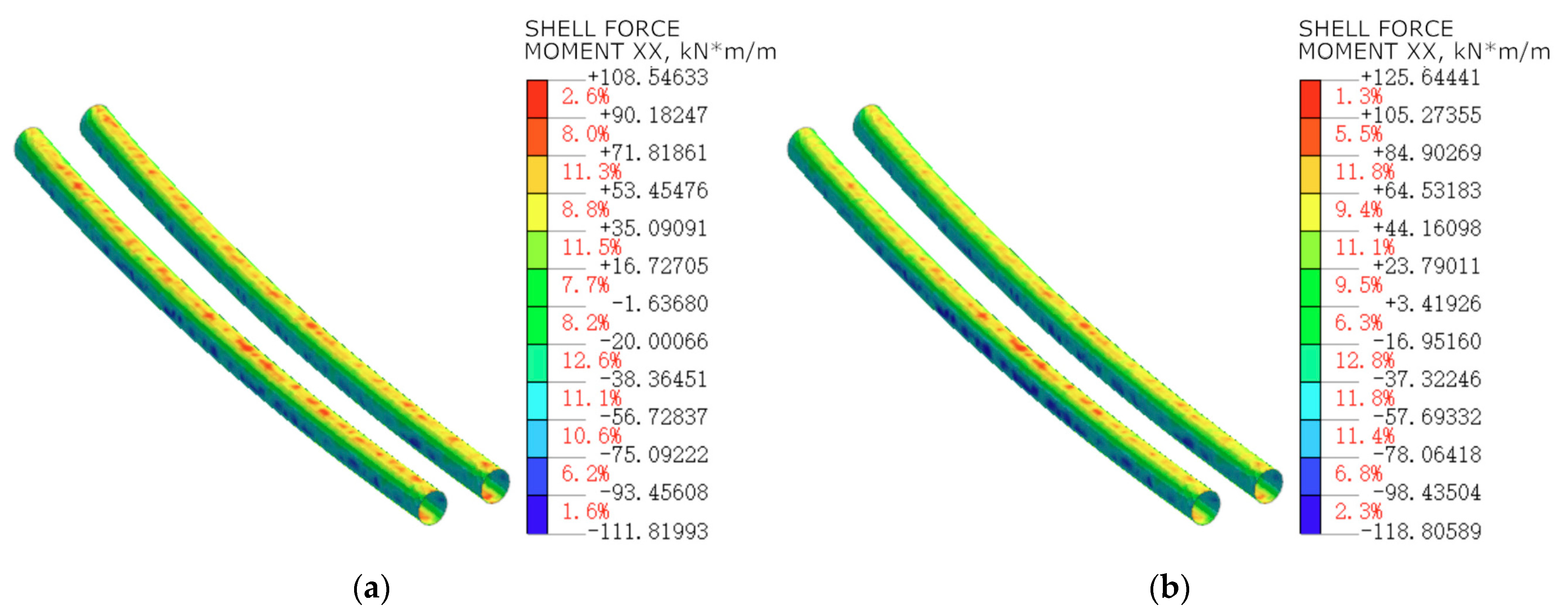
4.3.2. Analysis of Internal Forces in the Tunnel Structure

During pit excavation, the soil undergoes disturbance, leading to a redistribution of stress, thereby altering the internal forces within the tunnel structure. Comparison of the key parameters of rail transit structures before and after pit excavation is depicted in Figure 9, among which (a) and (b) show the comparison of the distribution of bending moments in the segment before and after construction, where positive and negative values correspond to tension and compression between the segments of the segment, respectively.
Before construction, positive bending moments are uniformly distributed along the tunnel arch, and similar patterns of positive bending moment distribution occur on both sides of the tunnel arch. With the maximum positive bending moment of 108.546 kN·m. However, after the construction positive bending moments become concentrated near the closest distance between the tunnel and the pit, with more noticeable tension between the segments of the left tunnel lining, leading to uneven deformation of the tunnel segments. The increase in the maximum bending moment is 125.644 kN·m, representing a 15.75% increase compared to before excavation. Thus after excavation, stress concentration also occurs at the crown of the right-side tunnel, but the concentrated distribution range is smaller than that of the left-side tunnel. Figure 9c,d illustrate the comparison of axial force distribution along the axis (i.e., the length direction) of the tunnel before and after excavation. Before pit excavation, the maximum axial force in the rail transit tunnel structure is 285.000 kN. After pit excavation, the axial force distribution in the tunnel remains largely unaffected. This is because excavation mainly changes the stress state of the soil around the tunnel, rather than directly affecting the tunnel axis direction significantly.
Figure 9e,f show the comparison of shear force distribution in the tunnel before and after excavation. Before excavation, the shear force distribution in the tunnel is generally uniform, ranging from −142 to 78 kN. After excavation of the foundation pit, the range of shear force variation remains unchanged. Excavation does not affect the shear force distribution in the tunnel, indicating overall force balance in the tunnel structure without the emergence of localized high stress zones. Different shear force distribution characteristics are observed at local positions of the tunnel. Near the excavation face, shear force extremes occur, and the concentrated shear force area on the left side tunnel is greater than that on the right side tunnel. In summary, excavation of the foundation pit significantly affects the bending moment distribution in the tunnel structure, but has no impact on the axial force and shear force distribution.

5. On-Site Monitoring and Discussion

5.1. Analysis of Tunnel Displacement Monitoring after Excavation

Further analysis of on-site monitoring data for the tunnel settlement and horizontal displacement within the excavated pit range is depicted in Figure 10. The settlement and horizontal displacement of tunnels within the excavated pit range are illustrated. Monitoring points are distributed at various milepost locations along both the left and right tunnels, covering the timespan from 8 March 2021 to 30 October 2023. Through a detailed analysis of the field data, an assessment of the tunnel’s deformation was conducted. The analyses are shown as follows:
(1)
Characteristics of settlement in the left tunnel. From 8 March 2021 to 30 October 2023, the overall settlement in the left tunnel exhibited an increasing trend. Specifically, the settlement at milepost Z11 + 210 and Z11 + 240 showed a gradual increase, while at Z11 + 270, the settlement initially decreased before increasing. This indicates the presence of non-uniform settlement along this section of the tunnel, which may have adverse effects on the structural safety of the tunnel.
(2)
Characteristics of settlement in the right tunnel. The variation in settlement in the right tunnel is rather complex. From 8 March 2021 to 30 September 2022, the settlement at most milepost locations exhibited negative values, indicating settlement phenomena. However, from 30 September 2022 to 30 October 2023, the settlement at certain milepost locations became positive, suggesting uplift phenomena in these areas. This alternating pattern of settlement and uplift may be associated with stress release and redistribution during the excavation of the pit. On the one hand, the excavation of the foundation pit causes a redistribution of stress and consolidation of the surrounding soil, resulting in the settlement of the tunnel. As the soil inside the pit is gradually removed, the pressure difference between the soil inside and outside the pit increases. In the early stages of excavation, the retaining structure can effectively limit the movement of the soil outside the pit toward the inside. However, as the excavation progresses, this limiting ability gradually weakens, causing the lateral stress of the soil outside the pit to move inward, disrupting the stress balance and resulting in rebound uplift. Additionally, during subway operation, the ability of the retaining structure to limit the movement of the soil outside the pit toward the inside also weakens.
(3)
Characteristics of horizontal displacement in the X-direction for the left tunnel. The horizontal displacement in the X-direction of the left tunnel exhibited some degree of fluctuation. From 8 March 2021 to 30 September 2022, the displacement at milepost Z11 + 180 changed from positive to negative, while at Z11 + 300, it changed from negative to positive. This indicates the presence of repetitive horizontal movement phenomena along this section of the tunnel. However, from 30 September 2022 to 30 October 2023, the displacement values at both milepost locations decreased, suggesting a gradual stabilization of the tunnel’s horizontal movement trend.
(4)
Characteristics of horizontal displacement in the X-direction for the right tunnel. For both monitoring points (mileposts Z11 + 180 and Z11 + 300), the horizontal displacement in the X-direction of the right tunnel generally exhibited an increasing trend. Over time, there were variations in the displacement rate. From 8 March 2021 to 30 September 2022, the displacement rate appeared to slow down, that is, the rate of displacement reduction decreased. However, from 30 September 2022 to 30 October 2023, the displacement rate increased, that is, the rate of displacement reduction increased.
(5)
Horizontal displacement in the Y-direction for both left and right tunnels. For milepost Y11 + 230, horizontal displacement in the Y-direction on both the left and right sides showed an increasing trend. From 8 March 2021 to 30 October 2023, the displacement on the left side increased from +0.85 mm to +1.2 mm, while on the right side, it increased from 0.79 mm to +1.8 mm. This indicates that the tunnel had undergone sustained deformation in this direction. Additionally, there was a difference in the displacement between the left and right sides of the tunnel. From the beginning of monitoring, the displacement on the left side was slightly higher than on the right side. Over time, this difference became more pronounced, especially in the data from 30 October 2023, where the displacement on the right side increased to +1.8 mm, while on the left side, it was +1.2 mm. This may indicate an asymmetric stress distribution or deformation in the tunnel structure along the Y-direction. All displacement values at the monitoring points were positive, as construction activities resulted in the tunnel moving in the positive direction along the Y-axis.
The monitoring data reveals varying trends in tunnel settlement at different times. The settlement in the left tunnel remained relatively stable throughout the observation period, showing no significant changes. However, the settlement in the right exhibited fluctuations, with the settlement at certain milepost locations gradually increasing over time. Horizontal displacement in the tunnels also demonstrated different trends at various time points. The displacement values in the X and Y directions of the left tunnel eventually stabilized, approaching zero displacement. In contrast, the displacement in the X and Y directions at larger milepost locations in the right tunnel continued to increase, with the displacement direction being toward the negative X-direction and positive Y-direction.

5.2. Tunnel Segment Deformation Monitoring Analysis

A three-dimension laser scanner was utilized to conduct three-dimensional scans of the tunnels within the vicinity of the excavated pit range. Data regarding the major and minor axes, ellipticity, and horizontal diameter of tunnel segments were extracted from December 2021 to February 2023. Subsequently, the maximum internal clearances between left and right tunnel segments were calculated at each milepost. The variation curve of the maximum internal clearances of left and right tunnel segments was analyzed, as illustrated in Figure 11.
During the monitoring period, at different milepost locations, the internal clearances between left and right tunnel segments exhibited some fluctuations. However, with the passage of time, these clearances gradually stabilized, showing no significant increasing or decreasing trends. The maximum internal clearances of both the left and right tunnel segments remained at 46 mm. Additionally, the variation in segment diameter was 7.6‰, indicating only minor changes in diameter during the monitoring period. These changes may be attributed to slight movements of the surrounding soil or minor deformations of the segments themselves. However, due to the small magnitude of these changes, their impact on the overall stability of the tunnel structure would be limited.
It can be concluded that the trends in the internal clearances from 2022 to 2023 show similarity, indicating that the surrounding soil and supporting structures of the tunnel gradually reach a relatively stable state. During this period, the tunnel structure did not experience significant deformation or displacement. This suggests that the tunnel structure, post-excavation, is capable of withstanding normal usage loads and environmental influences without experiencing severe deformation or damage.
By comparing numerical simulation results with on-site monitoring data, it was found that the settlement and horizontal displacement of the tunnel are highly consistent. For instance, the displacement on both sides of the tunnel was at the millimeter level. The maximum displacement obtained from numerical simulation was 3.5 mm, whereas the maximum displacement observed on-site was 1.4 mm, indicating a minor discrepancy at the millimeter level.
The slightly higher numerical results may be attributed to various factors affecting tunnel displacement, such as the construction quality of the protective structure, disturbance of geological parameters due to excavation, and water level fluctuations. Additionally, the results of the monitoring data are based on long-term monitoring, and under the effects of stress redistribution and support structures, the tunnel structure remains in a stable operational state over a long period, resulting in calculated displacement values being smaller than those from numerical simulations. While numerical simulations cannot fully capture all influencing factors, within the acceptable error range relative to the overall tunnel dimensions, the numerical simulation results used in this study are considered reliable.

6. Conclusions

Utilizing a three-dimensional finite-element analysis model of an on-site case, this study thoroughly studied the impact of foundation pit excavation on nearby tunnel structures. Detailed analyses of supporting structure deformation, surrounding ground settlement, and the effects of three stages of pit excavation on tunnel deformation, shear forces, and bending moments were conducted and compared with on-site monitoring results. The conclusions and recommendations are as follows:
(1)
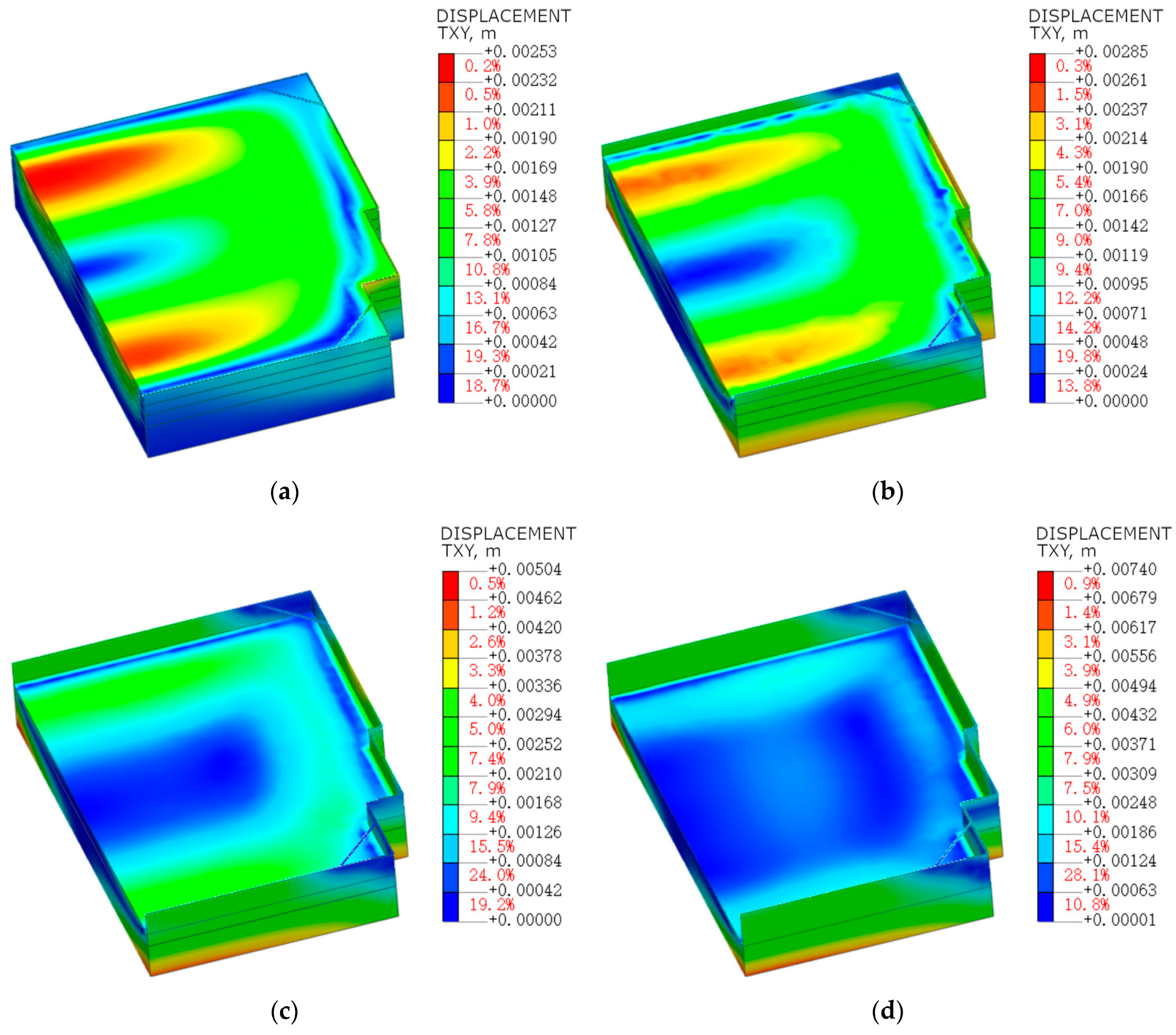
The supporting structure effectively managed soil deformation during the excavation, thus maintaining the stability of the construction pit. After the construction of the supporting structure was completed, the maximum horizontal displacement of the supporting structure was 2.53 mm, indicating that the structure could effectively control soil deformation and maintain stability. As the first stage of the excavation progressed, soil stress was released and redistributed, disrupting the original stress balance, resulting in a slight increase in the maximum horizontal displacement to 2.85 mm. During the second stage of excavation, the maximum displacement of the supporting structure increased to 5.04 mm. When the excavation approached the design depth (i.e., the third stage), the maximum horizontal displacement of the supporting structure reached 7.40 mm, at which point the lateral soil pressure and deformation were at their peak. The growth rates of horizontal displacement in the three excavation stages were 12.65%, 76.84%, and 46.83%, respectively. Despite the increase in horizontal displacement with deeper excavation, it remained below the specified control value, indicating that the design and construction measures of the supporting structure effectively addressed the changes in lateral soil pressure during the construction process.
(2)
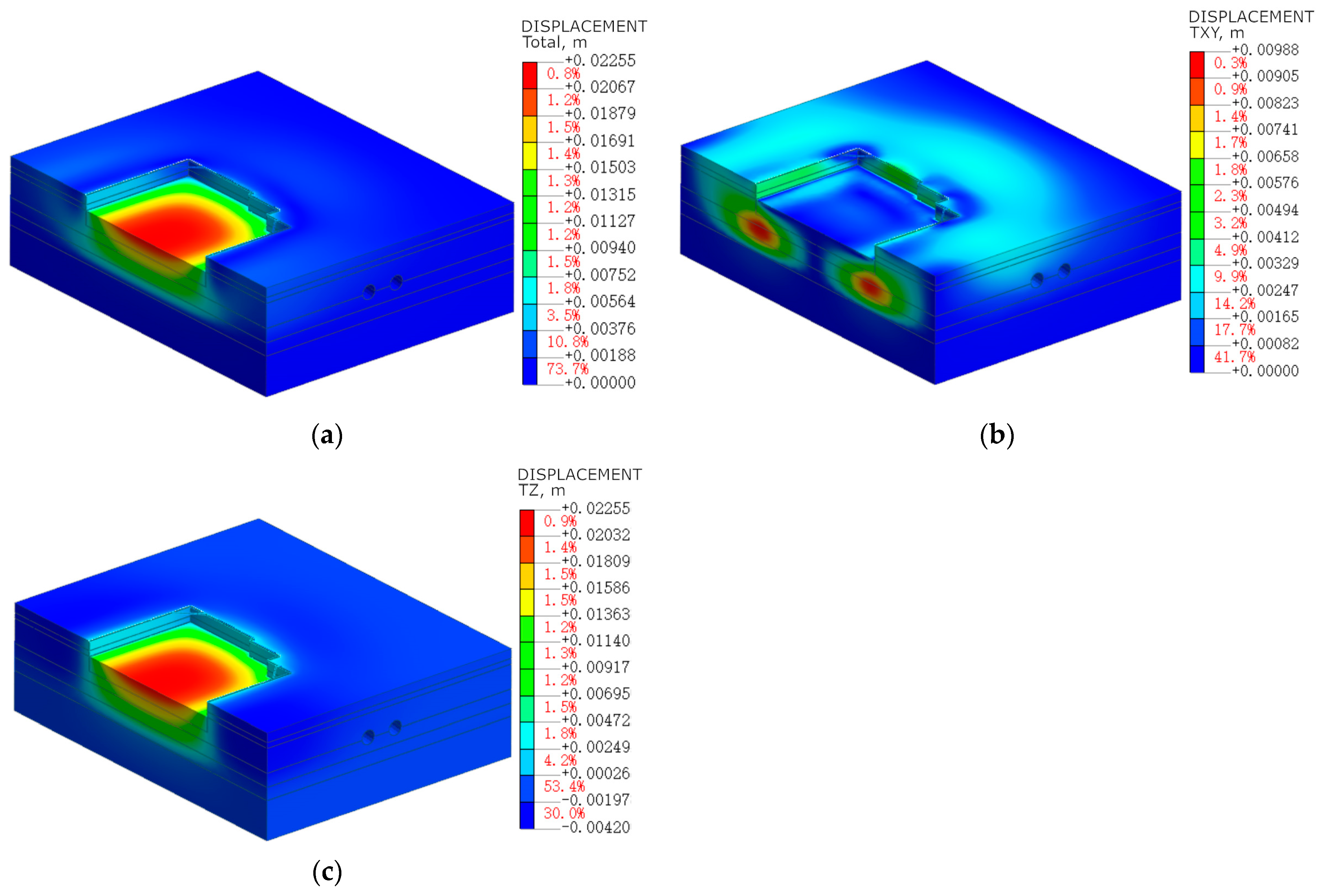
After the completion of the excavation, the soil near the sidewalls of the foundation pit was compressed due to the frictional effect of the supporting structure. The surface soil deformation exhibited a sinking trend, with a maximum cumulative settlement of 4.20 mm, and the soil horizontal displacement ranged between 0 and 1.65 mm. Vertical deformation primarily occurred in the bottom soil of the pit, with a maximum cumulative deformation of 22.55 mm, which was below the displacement control value of 30 mm, satisfying the relevant regulations. The horizontal displacement distribution at the bottom of the pit was uneven, with the maximum horizontal displacement of 9.88 mm occurring at the lower part of the corner due to stress concentration. The excavation of the foundation pit will cause significant ground settlement deformation at the center of the pit. However, this settlement gradually decreases with increasing distance from the edge of the pit. On the whole, the impact on the surrounding ground is relatively small.
(3)
Excavation of the foundation pit significantly affects the tunnel structure, leading to increased horizontal and vertical displacement. Prior to the excavation, the tunnel displacement was minimal, but as the excavation progressed, changes in the stress field led to tunnel deformation. During the construction of the supporting structure, the maximum horizontal displacement of the tunnel was 0.71 mm, which gradually increased to 6.08 mm during the excavation process. The maximum settlement of the tunnel was −2.20 mm during the construction of the retaining structure and stabilized at −1.32 mm through the three stages of excavation. The increase rates of the maximum settlement were 29.09%, 20.51%, and 6.45%, respectively. Overall, during the excavation of the foundation pit, the tunnel structure was significantly affected both horizontally and vertically, but as the excavation progressed, the tunnel structure gradually stabilized.
(4)
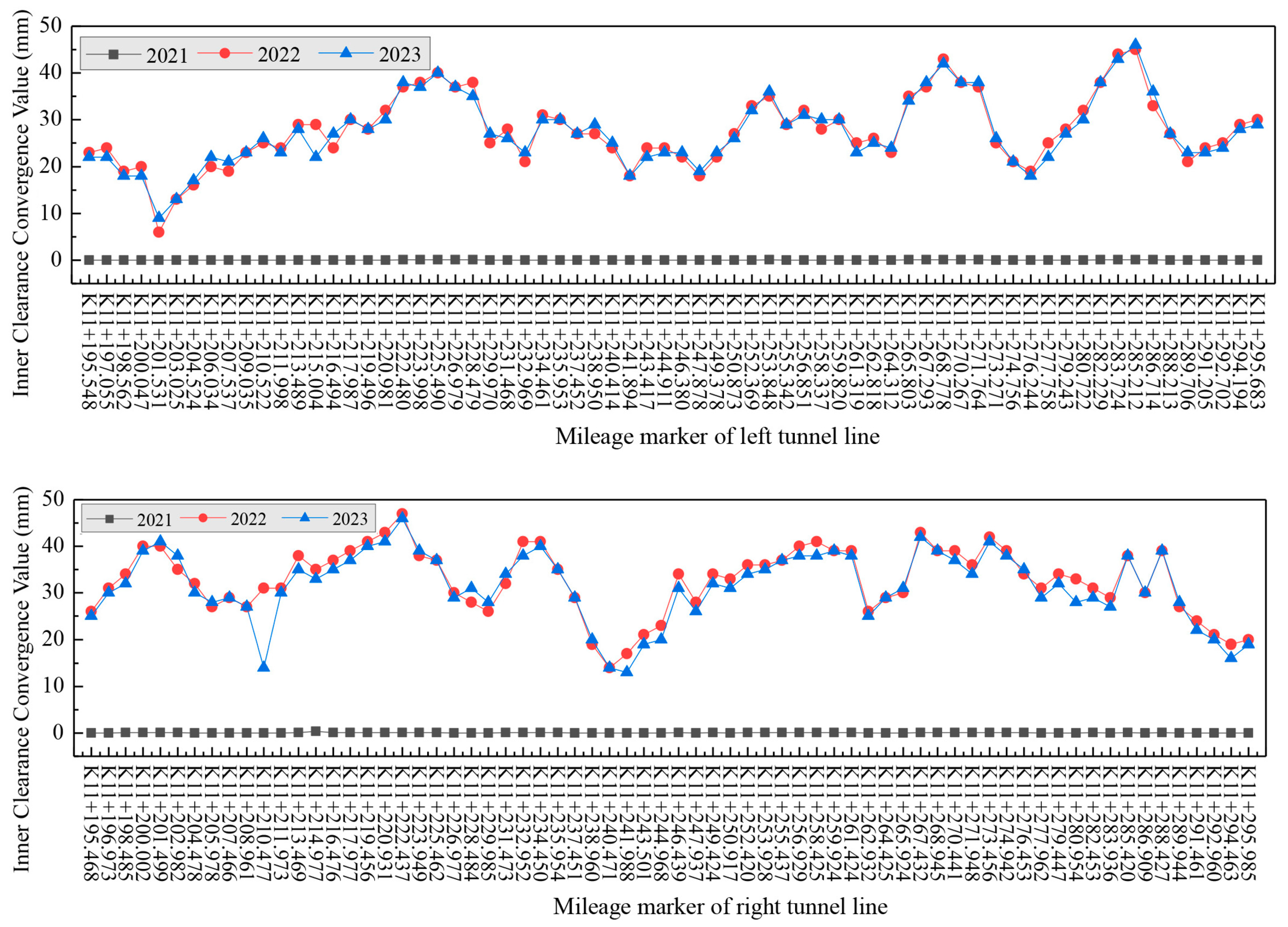
Comparison between the numerical calculation results and the monitoring data showed that the numerical calculations closely matched the on-site monitoring results, falling within the permissible error range. Specifically, the settlement of the tunnel structure was at the millimeter level, while the maximum settlement obtained from numerical results was 1.32 mm, which is 9% larger than the maximum settlement of 1.2 mm observed in field monitoring. Considering factors such as construction quality of the supporting structure, disturbance of geological parameters due to pit excavation, and water levels affecting tunnel displacement in real-world engineering conditions, numerical simulations may not capture all aspects comprehensively. However, these were minor differences occurring within reasonable limits, indicating the reliability of the numerical simulations used in this study. Additionally, three-dimensional scanning results from the site showed that the convergence values of the clear space within the tunnel segments on both the left and right lines remained stable. This suggests that soil deformation due to foundation pit excavation had minimal impact on the tunnel segments, essentially not affecting the operational safety of the subway system.
In summary, this study provides significant scientific visualization for the safety and stability assessment of similar tunnel structures adjacent to underground construction projects.

Author Contributions

Conceptualization, S.Y.; Methodology, K.G. and M.L.; Software, J.L.; Investigation, J.H., J.L. and K.G.; Resources, J.H., S.Y. and Y.L.; Data curation, J.L.; Writing—original draft, J.L.; Writing—review & editing, C.W.; Visualization, K.G.; Supervision, Y.L.; Project administration, J.H., C.W. and M.L.; Funding acquisition, C.W. All authors have read and agreed to the published version of the manuscript.

Funding

The authors acknowledge financial support from the Natural Science Foundation Youth Project of Hubei Province (JCZRQN202400959).

Data Availability Statement

Data will be made available upon reasonable request.

Conflicts of Interest

Author Kai Guo was employed by the company Wuhan Municipal Engineering Design & Research Institute Co., Ltd. Author Shan Yang was employed by the company China Railway Siyuan Survey and Design Group Co., Ltd. The remaining authors declare that the research was conducted in the absence of any commercial or financial relationships that could be construed as a potential conflict of interest.

References

  1. Lu, K.; Han, B.; Lu, F.; Wang, Z. Urban Rail Transit in China: Progress Report and Analysis (2008–2015). Urban Rail Transit 2016, 2, 93–105. [Google Scholar] [CrossRef]
  2. Awad, F.A.; Graham, D.J.; AitBihiOuali, L.; Singh, R. Performance of urban rail transit: A review of measures and interdependencies. Transp. Rev. 2023, 43, 698–725. [Google Scholar] [CrossRef]
  3. Han, B.; Yang, Z.; Yu, Y.; Qian, L.; Chen, J.; Ran, J.; Sun, Y.; Xi, Z.; Lu, F. Statistical Analysis of Urban Rail Transit Operations in the World in 2021: A Review. Urban Rapid Rail Transit 2022, 34, 5–11. (In Chinese) [Google Scholar]
  4. Ye, S.; Zhao, Z.; Wang, D. Deformation analysis and safety assessment of existing metro tunnels affected by excavation of a foundation pit. Undergr. Space 2021, 6, 421–431. [Google Scholar] [CrossRef]
  5. He, H.; Wang, S.; Shen, W.; Zhang, W. The influence of pipe-jacking tunneling on deformation of existing tunnels in soft soils and the effectiveness of protection measures. Transp. Geotech. 2023, 42, 101061. [Google Scholar] [CrossRef]
  6. Pei, Q.; Wu, C.; Ding, X.; Huang, S. A weight factor-based backward method for estimating ground stress distribution from the point measurements. Bull. Eng. Geol. Environ. 2023, 82, 365. [Google Scholar] [CrossRef]
  7. Liu, J.; Xue, B.; Wang, H.; Zhang, X.; Zhang, Y. Numerical study on the behavior of an existing tunnel during excavating adjacent deep foundation pit. Sustainability 2023, 15, 9740. [Google Scholar] [CrossRef]
  8. Zhang, X.; Wang, L.; Ma, M.; Li, W.; Wang, Y. Stability analysis of the foundation pit and the twin shield tunnels during adjacent construction. Buildings 2023, 13, 1000. [Google Scholar] [CrossRef]
  9. Xu, Q.; Xie, J.; Lu, L.; Wang, Y.; Wu, C.; Meng, Q. Numerical and theoretical analysis on soil arching effect of prefabricated piles as deep foundation pit supports. Undergr. Space 2024, 16, 314–330. [Google Scholar] [CrossRef]
  10. Wu, F.B.; Jin, H.; Zhu, S.K. Ground deformation characteristics of foundation pit related to the urban rail transit in Beijing. Rock Soil Mech. 2016, 37, 1066–1074. [Google Scholar] [CrossRef]
  11. Tan, Y.; Wang, D. Characteristics of a large-Scale deep foundation pit excavated by the central-Island technique in Shanghai soft clay. I: Bot-tom-up construction of the central cylindrical shaft. J. Geotech. Geoenviron. Eng. 2013, 139, 1875–1893. [Google Scholar] [CrossRef]
  12. Xue, D.L.; Yuan, J. Analysis of influences caused by cantilever pile-supported pit excavation towards adjacent buried pipe lines. Electron. J. Geotech. Eng. 2016, 21, 1089–3032. [Google Scholar]
  13. Wang, Z.; Guo, X.; Wang, C. Field monitoring analysis of construction process of deep foundation pit at subway station. Geotech. Geol. Eng. 2019, 37, 549–559. [Google Scholar] [CrossRef]
  14. John, B.B.; Hancock, R. Underground car park at the house of commons: Geotechnical aspects. Struct. Eng. 1977, 55, 87–100. [Google Scholar]
  15. Pei, Q.; Wang, X.; He, L.; Liu, L.; Tian, Y.; Wu, C. Estimation Method for an In Situ Stress Field along a Super-Long and Deep-Buried Tunnel and Its Application. Buildings 2023, 13, 1924. [Google Scholar] [CrossRef]
  16. Ng, C.W.W. Stress paths in relation to deep excavations. J. Geotech. Geoenviron. Eng. 1999, 125, 357–363. [Google Scholar] [CrossRef]
  17. Wang, Z.W.; Ng, C.W.; Liu, G.B. Characteristics of wall deflections and ground surface settlements in Shanghai. Can. Geotech. J. 2005, 42, 1243–1254. [Google Scholar] [CrossRef]
  18. Ng, C.W.W.; Zheng, G.; Ni, J.; Zhou, C. Use of unsaturated small-strain soil stiffness to the design of wall deflection and ground movement adjacent to deep excavation. Comput. Geotech. 2020, 119, 103375. [Google Scholar] [CrossRef]
  19. Hefny, A.; Al-Atroush, M.E.; Abualkhair, M.; Alnuaimi, M.J. Three-dimensional response of the supported-deep excavation system: Case study of a large scale underground metro station. Geosciences 2020, 10, 76. [Google Scholar] [CrossRef]
  20. Wan, J. Deformation characteristic of a supported deep excavation system: A case study in red sandstone stratum. Appl. Sci. 2021, 12, 129. [Google Scholar] [CrossRef]
  21. Lam, S.Y.; Haigh, S.K.; Bolton, M.D. Understanding ground deformation mechanisms for multi-propped excavation in soft clay. Soils Found. 2014, 54, 296–312. [Google Scholar] [CrossRef]
  22. Liu, B.; Lin, H.; Chen, Y.; Liu, J.; Guo, C.; Xu, X.; He, M.; Shang, J.; Zheng, W. Deformation stability response of adjacent subway tunnels considering excavation and support of foundation pit. Lithosphere 2022, 2022, 7227330. [Google Scholar] [CrossRef]
  23. Chen, B.G.; Jia, Z.P. Optimal strut position of deep foundation pit with convex corner under surcharge of adjacent building. Rock Soil Mech. 2023, 44, 2400–2408. [Google Scholar] [CrossRef]
  24. Wei, G.; Zhang, X.H.; Lin, X.B.; Hua, X.X. Variations of transverse forces on nearby shield tunnel caused by foundation pits excavation. Rock Soil Mech. 2020, 41, 635–644. [Google Scholar] [CrossRef]
  25. Zhang, X.; Wei, G.; Lin, X.; Xia, C.; Wei, X. Transverse force analysis of adjacent shield tunnel caused by foundation pit excavation considering deformation of retaining structures. Symmetry 2021, 13, 1478. [Google Scholar] [CrossRef]
  26. Liao, S.M.; Wei, S.F.; Shen, S.L. Structural responses of existing metro stations to adjacent deep excavations in Suzhou, China. J. Perform. Constr. Facil. 2016, 30, 04015089. [Google Scholar] [CrossRef]
  27. Ayasrah, M.; Qiu, H.; Zhang, X. Influence of Cairo Metro Tunnel Excavation on Pile Deep Foundation of the Adjacent Underground Structures: Numerical Study. Symmetry 2021, 13, 426. [Google Scholar] [CrossRef]
  28. Mi, C.; Liu, Y.; Zhang, Y.; Wang, J.; Feng, Y.; Zhang, Z. A Vision-Based Displacement Measurement System for Foundation Pit. IEEE Trans. Instrum. Meas. 2023, 72, 2525715. [Google Scholar] [CrossRef]
  29. Zhao, X.; Li, Z.; Dai, G.; Wang, H.; Yin, Z.; Cao, S. Numerical Study on the Effect of Large Deep Foundation Excavation on Underlying Complex Intersecting Tunnels. Appl. Sci. 2022, 12, 4530. [Google Scholar] [CrossRef]
  30. Zhu, X.; Chen, Z.; Ren, Y. Numerical Simulation Study on the Anchorage Mechanism of Yield Supporting in Deep Tunnel. Geotech. Geol. Eng. 2019, 37, 2091–2102. [Google Scholar] [CrossRef]
  31. DB 42/T159-2012; Technical Specifications for Foundation Pit Engineering. Hubei Provincial Housing and Urban Rural Development Bureau: Wuhan, China, 2012.
Figure 1. Schematic diagram of the project location.
Buildings 14 01853 g001
Figure 2. Plan view of the relationship between the excavation pit and the rail transit line.
Buildings 14 01853 g002
Figure 3. Cross-sectional diagram of the relationship between the excavation pit and subway Line 4.
Buildings 14 01853 g003
Figure 4. Computational model diagram: (a) Overall model; (b) Position schematic diagram.
Buildings 14 01853 g004
Figure 5. Horizontal displacement cloud maps of the excavation support structure during construction. (a) Construction of the retaining structure; (b) Excavation stage one; (c) Excavation stage two; (d) Excavation stage three.
Buildings 14 01853 g005
Figure 6. Displacement and deformation of the foundation pit after excavation. (a) Total displacement cloud map; (b) Vertical displacement cloud map; (c) Horizontal displacement cloud map.
Buildings 14 01853 g006
Figure 7. Horizontal displacement of the tunnel structure during construction. (a) Construction of the retaining structure; (b) Excavation stage one; (c) Excavation stage two; (d) Excavation stage three.
Buildings 14 01853 g007
Figure 8. Settlement of the tunnel structure during construction. (a) Construction of the retaining structure; (b) Excavation stage one; (c) Excavation stage two; (d) Excavation stage three.
Buildings 14 01853 g008
Figure 9. Comparison of primary parameters of the tunnel structure before and after pit excavation. (a) Bending moment before the excavation; (b) Bending moment after the excavation; (c) Axial force before the excavation; (d) Axial force after the excavation; (e) Shear force before the excavation; (f) Shear force after the excavation.
Buildings 14 01853 g009aBuildings 14 01853 g009b
Figure 10. Vertical displacement monitoring data of the (a) left tunnel and (b) right tunnel, and horizontal displacement monitoring data along the (c) X-direction and (d) Y-direction.
Buildings 14 01853 g010
Figure 11. Maximum internal clearance convergence values of the left and right tunnel segments.
Buildings 14 01853 g011
Table 1. Primary physical and mechanical parameters of the soil layers.
Soil Layer NameConstitutive ModelUnit Weight (kN/m3)c (kPa)Φ
(mm)
Eoedref
(MPa)
E50ref
(MPa)
Eurref
(MPa)
Poisson’s Ratio
1-2 Plain FillModified Mohr-Coulomb18.512101010300.35
6-3 Silty Clay Modified Mohr-Coulomb19.528141818540.3
10-2 ClayModified Mohr-Coulomb19.442163030900.3
13-2 Residual SoilModified Mohr-Coulomb18.927131616480.3
13-3 Colluvial SoilModified Mohr-Coulomb2128151717510.3
15b-2 Moderately Weathered Gravelly RockModified Mohr-Coulomb26.5116461001003000.25
Table 2. Structural mechanical parameters.
Structural NameTypeSection Size (mm)Unit Weight (kN/m3)E (Gpa)Poisson’s Ratio
Drilled PilePlate5732530.00.2
SupportBeam600 × 6002530.00.2
Crown BeamBeam1000 × 8002530.00.2
Shield Tunnel SegmentsPlate300 × 10002534.50.2
Table 3. Simulated construction procedures.
StagesConditionDescription
1Initial stress-field analysisActivate all geological layers
2Displacement zeroing-
3Railway transportation structureActivate the railway transportation structure and deactivate the internal soil mass
4Displacement zeroing-
5Enclosure structure constructionConstruct the enclosure structure
6Excavation stage oneDeactivate the soil within the excavation area for the first layer
7Excavation stage twoDeactivate the soil within the excavation area for the second layer
8Excavation stage threeDeactivate the soil within the excavation area for the third layer
Disclaimer/Publisher’s Note: The statements, opinions and data contained in all publications are solely those of the individual author(s) and contributor(s) and not of MDPI and/or the editor(s). MDPI and/or the editor(s) disclaim responsibility for any injury to people or property resulting from any ideas, methods, instructions or products referred to in the content.

