Abstract
In the era of the climate emergency and different pandemics, systems that can provide an immediate response to housing needs are required. This paper aims to evaluate the use of fibre-reinforced plastic polymers (FRPs) to satisfy this need. In particular, a modular emergency housing system that utilises FRPs for structures and cladding is proposed, which proves adaptable to both different uses and different kinds of temporary or permanent buildings. By adapting modular emergency housing to different contexts, developing an integrated design process (IDP) and building information modelling (BIM) methodology, this research aims to provide innovations for the the architecture, engineering, and construction (AEC) sector, including FRPs, through a digitised approach, applied also to an experimental case study. A pilot unit of the modular emergency housing system, a nearly zero-energy building (nZEB), is described in detail, while laboratory tests are reported. Construction considerations confirm the sustainability and highlight the adaptability of the modular system to different housing needs conditions, justifying the possible future development of supply chain industrialisation supported by the presented methodology.
1. Introduction
To cope with the climate emergency or a pandemic, systems able to provide an immediate response to housing needs are required. In such situations, the time of realisation must be reduced, the assembly system must ensure the short duration of the on-site construction, energy sufficiency has to be achieved, and the ecological footprint has to be minimised, considering building-induced climate warming [1].
For these reasons, interest in the prefabricated house industry from both investors and buyers has been growing in recent years [2]. Prefabricated homes offer several attractive advantages compared to traditional on-site construction methods, such as a substantial reduction in construction time, higher quality control, and potential cost savings [3].
Just as a traditional construction involves different construction methods, and different materials are used, prefabricated houses can also be divided into two main groups, namely panel buildings and modular buildings [2], made with different technologies and different combinations of materials. Modular housing is defined as “housing that is partially built in a plant, shipped to a development site, and placed on a foundation, where the roof structure and exterior finishes are completed” [3]. Panelised housing is a similar construction technique that utilises wall panels manufactured in a controlled environment, shipped to the construction site, and installed on the prepared foundation [4].
Modular construction is the primary method of off-site construction [5]. Kim comparatively assessed the total energy consumption, resource use, environmental impacts and waste generation in the construction phase of a modular home and a conventional home [6]. Similarly, cradle-to-gate life cycle analyses (LCAs) were conducted by Kamali [7,8,9,10,11] to compare the environmental impacts produced by the construction of different modular and conventional buildings.
Emergency housing can be also subdivided into two main categories: shelter and house (housing).
A shelter offers a safe area to live in the moments immediately following a disaster, providing protection from the elements, personal safety, access to drinking water and sanitation, proximity to places of work, education, and health facilities. A house, meanwhile, refers to accommodation where, in addition to the aspects already present in a shelter, it is possible to recreate the daily routine and household activities [12]. A house guarantees personal hygiene conditions, prevents the spread of diseases, and ensures privacy. Furthermore, by re-establishing the daily routine, it restores dignity to the displaced person and a sense of normality in life and the community. Housing also has an important impact on the psychological state of the people affected from the disaster [13].
Under these conditions, among prefabricated building systems, this research investigates the possibility of providing an immediate response to housing needs, using a modular housing system, replacing conventional materials such as steel and aluminium with fibre-reinforced plastic polymers (FRPs) for structures and cladding. To make this system competitive with other prefabricated solutions and to move the FRP building sector toward Industry 4.0, an integrated design process (IDP) for the FRP modular system supported by a building information modelling (BIM) methodology is proposed. This methodology rapidly optimises the modular housing systems according to their use, dimensions, and location.
This paper also provides new contribution towards the literature, in which a low number of studies and realisations have been performed to investigate FRPs’ sustainability in buildings [14]. In the UK in 2012, the Starlink Lightweight Building System (SLBS) led to the construction of a pultruded FRP test house in Bourne, Lincolnshire. However, the concepts of profiles and snap-fit connections were not continued. Instead, simpler and fewer pultruded FRP profiles with easy-to-assemble connections were used for a new test house [15], which was supported on composite piles [16]. In structural engineering, FRP is backed by numerous theoretical studies and applications [17,18,19,20]. The challenges include connections and joints for FRP members [15], as well as flexural performance [21,22]. Furthermore, FRPs offer many benefits for building construction: they are lightweight, strong, corrosion-resistant, and durable [23,24].
Due to the properties of FRP themselves, the manufacturing costs can be significantly decreased by the speed of building the house, and by the seriality and modularity of the production. They are, in fact, stable and torsion-resistant, and they have anti-corrosive and anti-magnetic properties. FRPs are also not electrically conductive, an extremely useful property in the field of electrical installations.
Widely used in the chemical sector, FRPs are not yet widespread in the building sector due to the rigidity of the reference market, the scarcity of skilled labour, and the higher costs of the production processes, which are not currently industrialised for the building market, meaning that they are still not able to create significant economies of scale.
Through the investigation of the use of FRPs both for structures and cladding in modular emergency housing systems, this paper aims to concretise the concept of smart living, i.e., intelligent living. This is an initiative of the Lombardy Region, through the Lombardy 5.0 proposal, involved in promoting development and innovation on different topics such as ecological impact, new materials, domotics, and intelligent management and monitoring systems by focusing on the possibility of creating a product capable of penetrating the market.
Similarly to other prefabricated construction technologies, FRPs allow the optimisation of the manufacturing process, provide a freedom from maintenance needs (a benefit in the economic analysis), and involve decreased carbon emissions during material processing and assembly. A total of 40% of global energy consumption is related to the building sector. In fact, major refurbishments and improvements to the built environment are urgently needed in order to minimise the ecological footprint and ensure energy sufficiency [1].
Unlike traditional construction systems, which are mainly based on labour-intensive, handcrafted components assembled onsite, FRP systems can respond positively to the contemporary needs of daily life, ensuring high performance and reliability, as well as reducing construction time and installation costs. Several positive benefits in using these construction technologies can be achieved in new buildings, but also the refurbishment and retrofitting of existing buildings can be included.
An emergency building must guarantee simple and effective buildability and, at the same time, reliability and durability.
In the literature, different studies focus on emergency systems [25,26,27,28,29,30] and underline the needs of this construction type, which requires a rapid construction time schedule. Song [31] highlights that the construction speed increases the required energy, especially for the structures. He argues that it is therefore crucial to reduce the energy during the life cycle in order to improve the performance and sustainability of the units. To obtain this, the following guidelines are described:
- Use recycled materials to reduce energy consumption for construction;
- Choose a lightweight structure that has low energy for construction;
- Use a light cladding such as wood to reduce energy for construction
- Use composite walls with air spaces (to be chosen carefully to reach the optimal conditions) and insulation.
As these guidelines suggest, the presented research is oriented towards the use of structural and cladding elements to build walls with air spaces, based on glass fibres. This choice satisfies the listed requests, with FRPs being a recyclable [32] and lightweight material, allowing for easy transport and rapid assembly, even by unskilled workers.
Towards a holistic approach [18] in the research, these elements enable easy maintenance and provide high acoustic performance for the partitions, both for acoustic insulation and for any requested sound absorption, as well as optimal indoor comfort, as was confirmed when the pilot building was completed. The identified building systems allow for the reuse of the components and/or living/working modules and their easy handling in the case of changing conditions. The building envelope minimises possible thermal bridges. The building system is designed to use renewable energy sources, with the integration of photovoltaic systems in the roof. To assist people both in emergency conditions and in their daily life, domotic systems are included, which allow for an extension of the functional capacities of the occupants.
FRPs are widely accepted in the strengthening of existing structures, where they are also used in combination with reinforced concrete, steel, wood, and masonry, but they are not yet commonly preferred for new buildings, while the first construction applications have concerned infrastructures, bridges, motorway decks, stairs, and shelters.
At the same time, the scientific community has not neglected the study and analysis of the environmental performance of this material, particularly comparing its performance with concrete, the main material generally used in the civil sector [7]. It is now known how the use of this material for the construction of infrastructures contributes to the reduction in environmental impacts [8], both in terms of production and disposal, combining these peculiarities with other fundamental characteristics, such as easy recyclability. Recent studies have analysed and demonstrated the mechanical properties of the recycled fibres reintroduced into the production cycle [9].
The material properties are well known nowadays, and the main ones, which have been deemed favourable for the realisation of the rapid construction of houses, in cases of emergency and in cases of necessity to reduce the construction costs linked to the worksite schedule, are listed in detail below.
1.1. High Strength to Weight Ratio
FRP profiles are 70% lighter than steel and 30% lighter than aluminium, but at the same time, they are resistant and strong. The mechanical properties of composites are generally high in the longitudinal direction, which coincides with the direction of the pultrusion process. Resistances in that direction are comparable to those of steel, with an elastic–brittle behaviour.
Because of their weight, the profiles are easy to handle, transport, and install. This feature helps to save time on projects and simplifies installations in remote locations. They also have a low response to inertial forces, relevant for building structures in seismic areas [33].
1.2. Durability
FRP profiles have the ability to withstand environmental agents and highly aggressive chemicals, especially acids, alkaline substances, and solvents. Compared to metal materials, they never rust. Beyond this, their dimensional stability allows them not to be affected by large temperature fluctuations, so no significant or permanent sectional deformations are presented [34,35,36].
Their intrinsic durability makes FRP profiles suitable for outdoor structures. They are used for the construction of walkways, handrails, architectural elements and furnishings, poles, and fences.
1.3. Insulation
FRPs do not require grounding, thanks to their high level of electrical insulation, and their low coefficient of thermal conductivity ensures high thermal insulation.
Fibreglass materials have a thermal conductivity coefficient of around 0.3 W/mK, which is low compared to that of aluminium and steel.
For this reason, FRPs already find widespread applications in windows and doors, and also in concrete sandwich panels [37], where they make a significant contribution to energy savings [38].
1.4. Design Flexibility
Another feature that promotes the use of FRPs is their design flexibility. The profile design, in fact, can be easily customised—their dimensions, thickness, and form complexity can be defined by designers who feel free to create new products easily.
The properties of this material therefore make it possible to create “customised” buildings, coupling solutions that can be easily integrated with energy efficiency systems, achieving high indoor comfort. These characteristics are suitable for both emergency houses and permanent buildings. The comfort and quality of the internal environment that can be achieved, unusual for emerging housing units, allow for addressing a vast real estate market, not only for emergencies but also for permanent, long-term interventions.
The development of models and construction technologies based on the optimisation of the raw materials, introducing an innovation both in the building process and the product process, can become a fundamental topic in the next few years, as shown by Lahmann [39].
1.5. Competitive Profiles
FRP profiles could be competitive because their applications are not limited only to emergency constructions, for which they were developed, but they can also be applied to the civil and industrial construction market in general (worker villages connected to infrastructural works, areas with a tourist vocation, etc.). They can also be used in the renovation process for existing buildings.
Generally, prefabricated construction technologies allow for the optimisation of the manufacturing process, as well as decreasing the carbon emissions during material processing and assembly [40].
Differently from traditional construction systems, which are mainly based on labour-intensive, handcrafted components assembled onsite, preassembled construction systems are able to respond positively to the contemporary needs of daily life, ensuring high performance and reliability, as well as reducing construction time and installation costs [41]. Both in new buildings [14] and in the refurbishment and retrofitting of existing buildings, several positive benefits of using FRPs can be obtained. Often, in the refurbishment of existing buildings, the need to reduce the costs of on-site construction without decreasing the level of precision of the assembly may be a crucial priority. In the future, a comparative analysis on the possible construction methods using FRPs could consider costs and benefits [2], as well as an efficient strategy for the energy retrofitting of the housing stock [41] and green building certification [42], including the digitisation support.
This paper highlights the digitisation of building processes for FRP modular systems as a key innovation for the architecture, engineering, and construction (AEC) sector [43]. This is crucial because the construction industry has low digitisation levels and slow growth compared to other sectors [44,45]. The design and maintenance of FRP modular systems need a methodology to quickly optimise housing based on use, dimensions, and location, pushing the building sector towards Industry 4.0 [46].
Section 2 outlines this methodology for developing an integrated design process (IDP) for FRP emergency units, supported by building information modelling (BIM) to quickly control and optimise modular housing system properties. Section 3 presents a case study of an FRP modular house emergency system. Section 4 describes the building process of a pilot unit, from design to laboratory tests and construction. Section 5 analyses the results, followed by presenting the conclusions.
2. The Methodology to Develop an Integrated Design Process (IDP) for Modular Houses in FRP
This research project on modular houses is intended to be a representative of lightweight design, capable of adapting to different contexts, from an emergency situation to any kind of temporary or permanent building settlement that includes different activities in places located all over the world.
Because of the various specialised affiliations that must converge throughout a building’s life cycle, in order to ensure building performance such as architectural quality, high indoor comfort, energy efficiency, and speed of construction, this research work is characterised by a highly complex building process. To achieve a successful outcome, an IDP, supported by a BIM methodology, has been found to be one of the most important supporting factors. Digitisation is seen as a significant innovation in the architecture, engineering, and construction (AEC) sector, facilitating the introduction of FRP systems in the built environment.
The IDP for an FRP modular housing system uses an interdisciplinary approach, fostering collaboration among all parties. This cooperation among professionals creates an effective process that considers many factors in building physics and architecture, including optimising energy performance.
The specific steps and strategies to be adopted are directly related to the design intent and input, capable of adapting modular emergency housing to different contexts, which may vary depending on the possible thermal zone and use of the house. In the presented case study, a procedure was established using a building execution plan (BEP) to implement the prototype emergency unit in Milan, northern Italy, but the presented BIM methodology allows the BIM model to be adapted to energy simulations with different climate conditions.
This procedure helps to eliminate barriers and limitations to effective and efficient collaboration with the various fields. The use of BIM allows for the integration of information coming from the participants in the project relating to the different disciplines, which traditionally operate in distinct phases of the process.
In addition, to ensure efficient collaboration between the figures involved, the BIM methodology integrates the information (architectural, structural, plant engineering, energy, management, etc.) into a single model, which is useful at each stage of the building process. The BIM model includes data on FRP structures, the acoustic and thermal properties of the envelope, the thermal load specifications, and the parameters for thermal zones and plant efficiency.
Because FRP structures have a strong influence on a multitude of the involved disciplines in the project and a strong impact on the structural system itself, an integrated structural process model must be added.
Addressing this challenge requires including, in the methodology, an effort to improve knowledge of the performance design of the building, as well as the process of obtaining and exchanging information between the specialists involved in the development of the building project.
The BIM team are suggested to incorporate architecture, structures, acoustics, energy, environmental engineering, and home automation in their activities to optimise costs and maintenance operations.
In this way, inconsistencies between the different design levels, times and costs are reduced, and a database for the planned interventions can be set up [47].
By appropriately characterising the model with the information derived from the database, a BIM model that faithfully reproduces the project is created.
The BIM authoring software (Revit 2017) allows the experts to first define structures, walls, slabs, ceilings, roofs, and windows using parametric families which virtually represent the building components in the real world. The parametric families are updated based on field conditions and simulation results, allowing the easy adaptation of the methodology for different uses, dimensions, and locations of modular housing, and simplifying data evaluation. The combination of all of these objects determines the model. The development of the three-dimensional model and the design of the project database lays the foundation for the real operative phase because the model does not contain only geometrical information but also presents information of a specific nature.
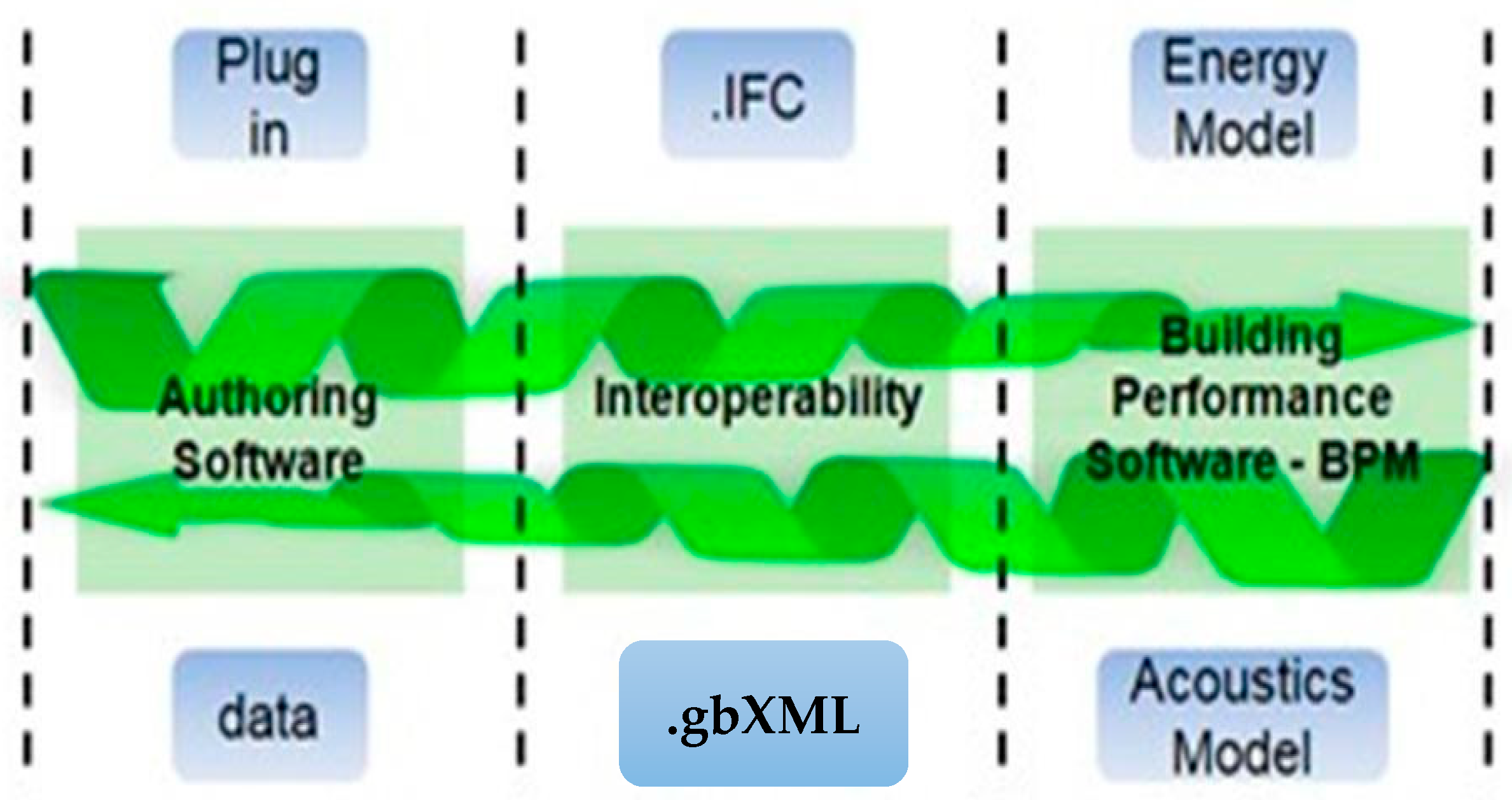
To include acoustic, structural, and energy analysis in the process, the BIM’s interoperability is considered, and the Industry Foundation Classes (IFC) format is taken into consideration. The most frequently mentioned issue and the most researched topic is the “interoperability” between BIM and other building performance models (BPM) such as the building energy modelling (BEM) [48,49], and the building acoustic modelling (BAM) (Figure 1).
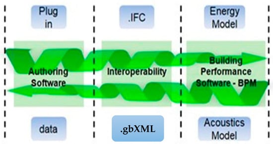
Figure 1.
BIM/BPM interoperability through externally executed codes that exchange information via standardised exchange files.
Nevertheless, the interoperability is rarely perfect, and information is lost during translation from the BIM authoring tool to the simulation software [50]. The discrepancies in data translations from the BIM authoring tool to specific calculation virtual environments (CVE) for structural, energy, and acoustic evaluation must be considered. The architectural model is converted into an analytical model in order to perform different types of assessments in CVE [51], defining the interoperability paths from BIM to CVE for structural, energy, and acoustic evaluations [52,53].
The architectural space in the BIM tool serves as a bounded analytical space, functioning as a characteristic model in the CVE, for example as a thermal zone in the BEM [54]. Specialists use this space to store thermal specifications (e.g., occupancy rate, ventilation rate, temperature set points) for conducting static and dynamic heating and cooling analyses, ensuring compliance with standards.
BIM can be used to deliver information about room geometry and material characteristics; however, currently available software cannot perform acoustic analysis using BIM enriched with acoustical data.
For this reason, in the digital model of the building in the IFC format, a list of auditable elements is compiled in the prediction calculation of performance, according to the ISO 12354 standard [55]. These elements can be measured for proof tests at the completion of the work according to the various standards (standard ISO 16283 [56]). Substantial benefits in the different stages of predictive and survey calculations are achieved.
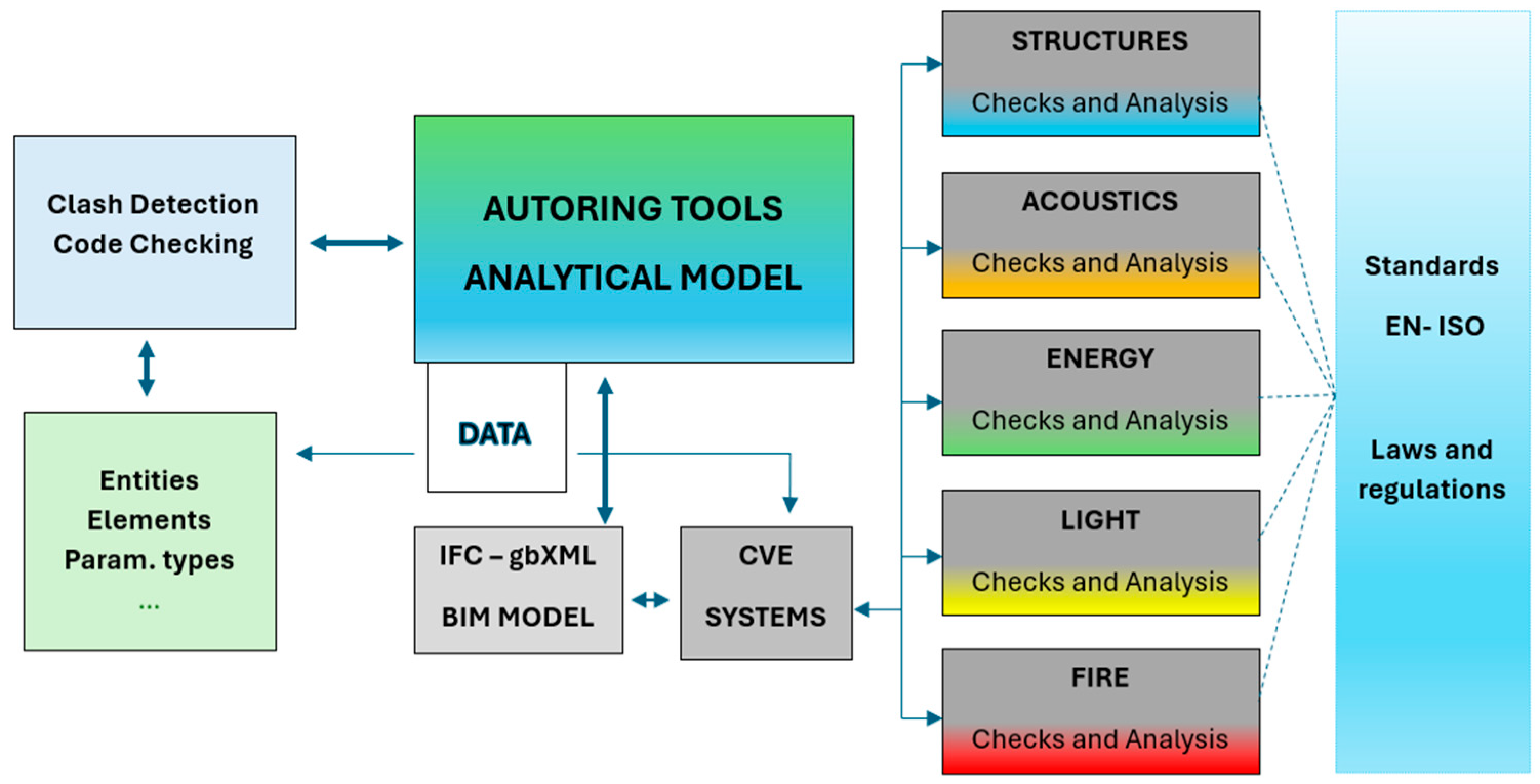
Within the BIM model, shared parameters are transformed into editable fields in the properties interface, increasing the interoperability and integration of BIM/BPM (building performance models) (Figure 2).

Figure 2.
Methodology workflow.
In the case study, interoperability was verified through an initial BIM validation, followed by clash detection and code checking [52]. This thorough modelling process ensures that the model includes all required attributes and is useful for the entire team [57]. However, while flawless interoperability is theoretically possible, it is not always achieved in practice, leaving this an open research topic [58]. In the presented study, an evaluation of the systems for calculating and verifying the thermal bridges is also included in the CVE. This is useful for checking the insulation properties of FRPs to achieve the results required for buildings to fall into the nearly zero-energy building (NZEB) category.
Since this research work is part of a smart living project, involving the development of innovative “building-system” systems for the effective and efficient integration of air conditioning systems and energy services in buildings, particular reference is given to renewable sources.
The design phase of a building is of primary importance for the energy efficiency and the reduction in the energy demand. The implementation of NZEBs involves multiple aspects, as follows:
- Complying with existing energy standards and legislation;
- Adapting to the local climate and specific characteristics (site of archaeological or traditional interest);
- Clearly defining the project objectives and following the sustainability principles for a successful implementation;
- Considering all recent and innovative technologies and ensuring technical and financial feasibility;
- Working in compliance with the decisions and agreement of the interdisciplinary team of specialists.
Since this research aimed to underline the advantages of using fibreglass, highlighting the ease of installation and of reuse and the short duration of construction time, a 4D modelling step was considered in the process [59,60].
This is the step in which the concept of integrating the space/time binomial is introduced into the model. The model becomes implementable with the three spatial dimensions, achieving the goals of virtual design construction, as a computer simulation of the definition and development of a construction process (UNI 11337 [61]). In fact, through the creation of a virtual prototype, it becomes possible to integrate project teams and strategies that until this step remain separate from the building project.
The creation of a virtual built model that can then be broken down and thoroughly examined reduces construction-related risks, thus simplifying predictions of possible logistical/design conflicts, resulting in a leaner, faster, and less costly process.
3. The FRP Modular House Emergency System Case Study
In the presented research, a preliminary concept was developed, starting from basic cells to be duplicated to form buildings of different dimensions and to create a small village.
The integrated design and construction process for modular houses in FRP was applied to the pilot building.
Preliminary Concept
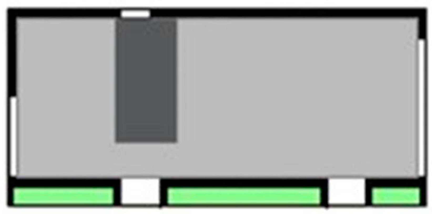
Firstly, a preliminary step of the project defined the concept of a basic cell/basic form. In this study, a small housing unit of ca. 45 m2 (Figure 3) was identified. Secondly, the unit was duplicated to form buildings of different dimensions and was redistributed to create a small village. The basic module includes a room with two beds, a bathroom, a living room with kitchen (Passive Unit), and an energy unit (Active Unit). The energy unit, as well as the PU, is used to create a single nearly zero-energy building basic cell, with predispositions for connections to energy networks.

Figure 3.
The basic cell. The active unit (green area) and the passive unit (bathroom in the dark grey area).
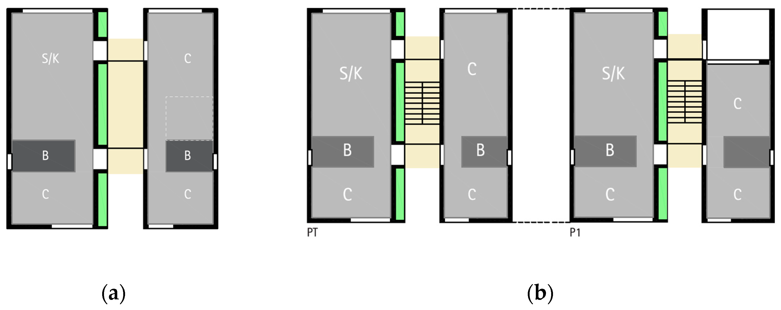
The basic module was enlarged to accommodate up to four to six people.
More modules can be merged in order to accommodate up to a maximum of 80 people (Figure 4).
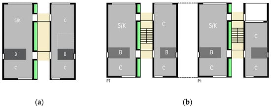
Figure 4.
Redistribution of modular units to accommodate an increasing number of people. Four to six people (a) and eight to ten people across two floors, PT and P1 (b). Bathrooms are located in the dark grey areas (B), bedrooms (c) and living rooms with kitchen (s/k) are coloured light grey.
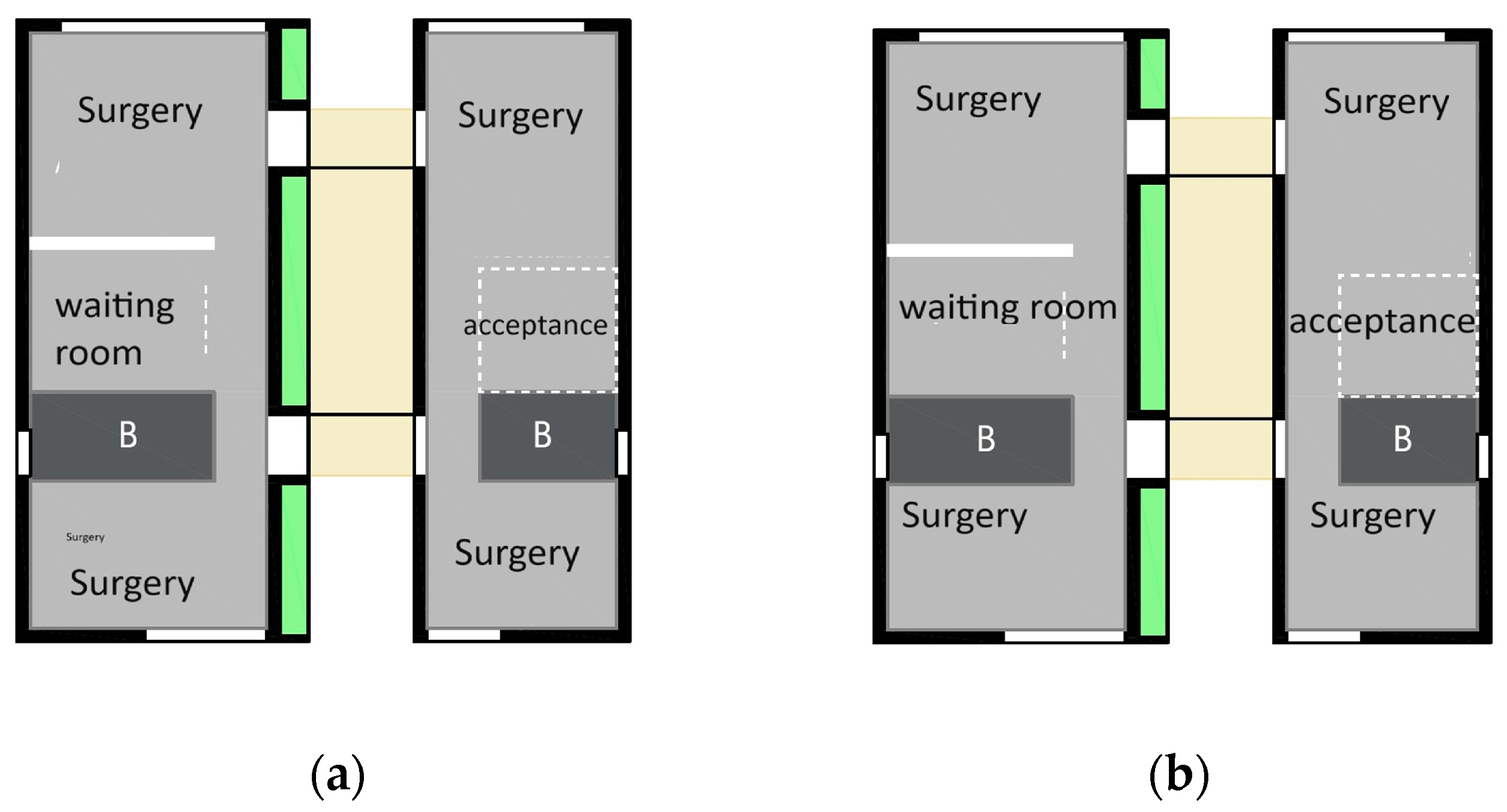
The larger housing modules, for four to six people, constitute a development of the basic module, and are also designed to accommodate different activities that are necessary in an emergency (Figure 5).

Figure 5.
Modular units for a surgery (a) and office activities (b).
The basic module is made of FRP portal frames. The foundation can vary according to the construction site conditions.
The energy unit is thought of as a “plug in” box system to be added on one side of the house, to be easily installed in emergency conditions.
For emergency conditions, in the module basement (between ground level and the floor frame supported by the piles), rainwater storage, electrical storage, and a container with chemical solvents to accommodate the sanitary drains are inserted (in the absence of sewer drains). This equipment makes it possible to transform the unit into a ZEB module [20].
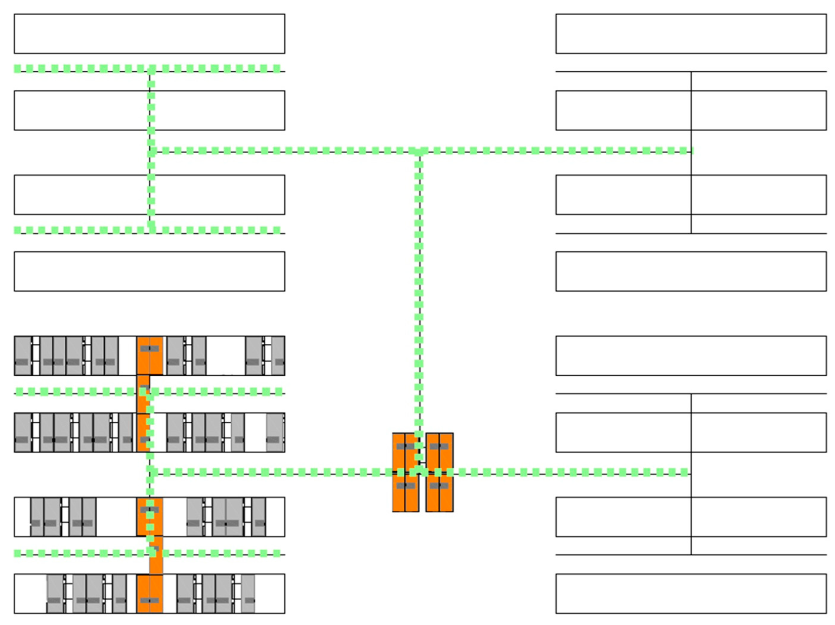
As the quantity of modules increases, in particular when 20 residential modules are present, the development project envisages the partial replacement of the individual energy units with a single energy house and a relatively common distribution network for the production of thermal energy for climate control (Figure 6). In this case, the sharing of mixed networks (WiFi and/or wired) is necessary for the centralised management of the main service systems associated with the users (climate control, security and surveillance, and the development of support networks for emergencies and rescue).
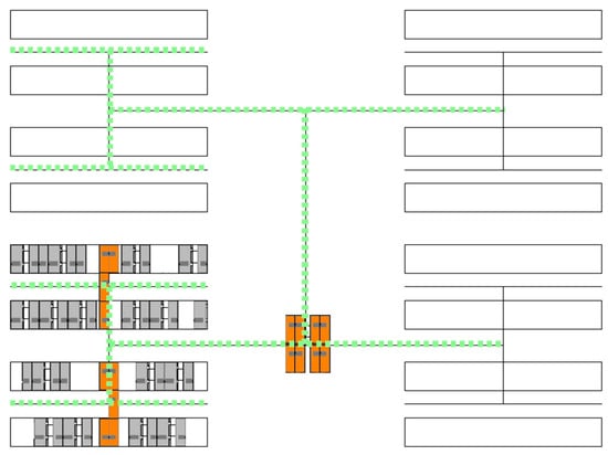
Figure 6.
Energy grid (energy net green line and orange energy house) and modular units’ distribution.
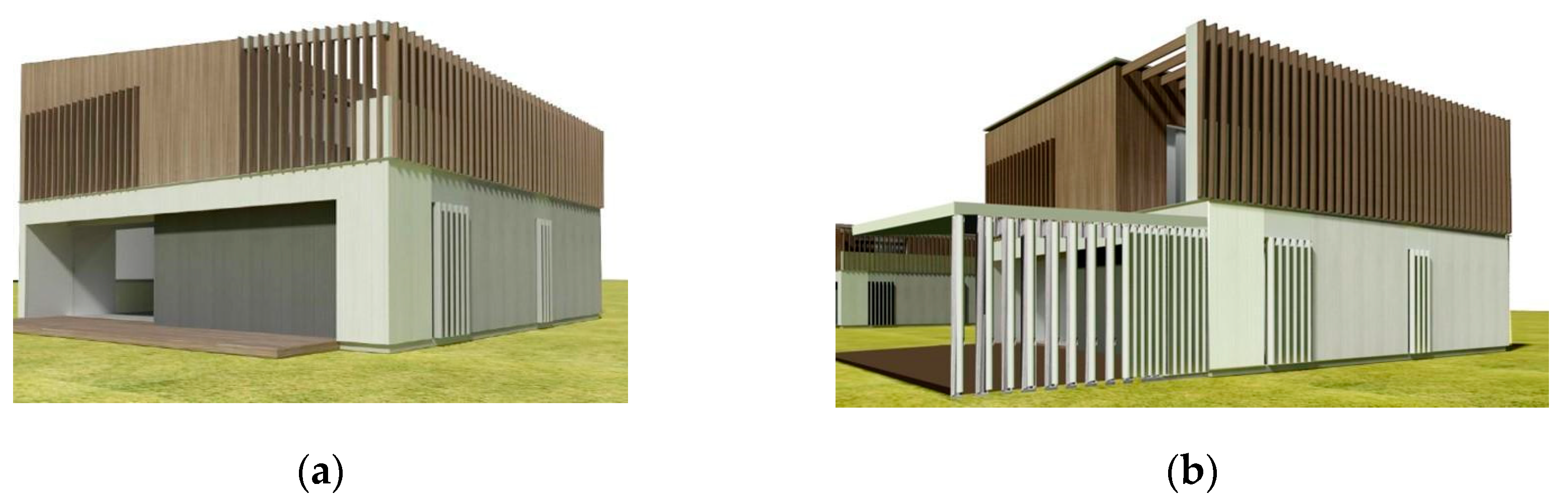
The design and implementation of the basic module define a new supply chain model. Starting from a standardised and industrialised design process, a customisable basic module can be developed by choosing among various facades and roofs (Figure 7) according to the climate conditions, suitable not only for emergency buildings but for “permanent” buildings characterised by a specific architecture (Figure 8).
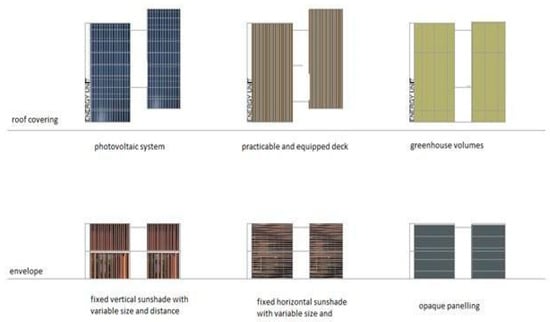
Figure 7.
Customised solutions to apply to the basic unit: roof covering (photovoltaic system, practicable and equipped desk, greenhouse volumes), envelope (fixed vertical sunshade with variable size, fixed horizontal sunshade, opaque panelling).
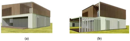
Figure 8.
Customised modular buildings without a pergola structure (a) and with a pergola tent (b).
4. The Pilot Building
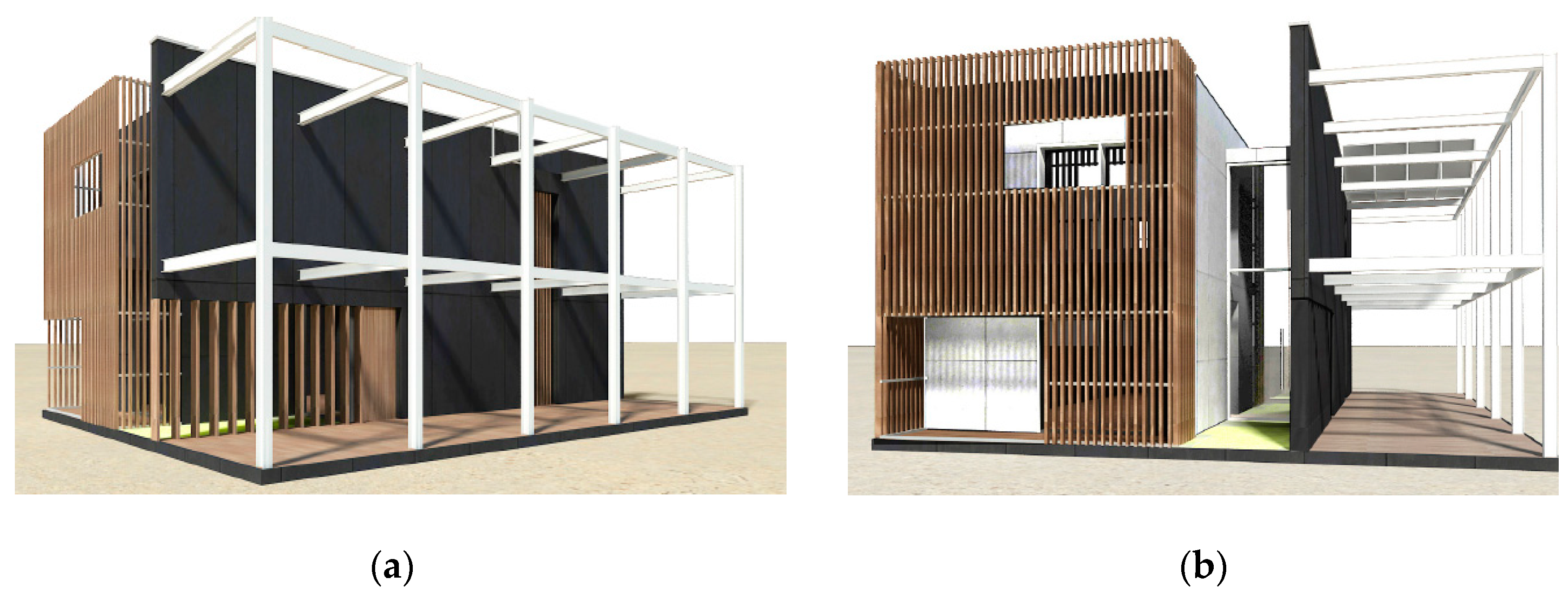
The prototype houses two stacked base units, a connection area (open air stairs included), and an energy unit. It consists of two parallel blocks each, with an area of ca. 130 m2 across two floors (Figure 9). One block is entirely realized, housing the two base units, and is equipped with vertical internal walls, window frames, and solar shading systems (Figure 10).
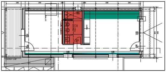
Figure 9.
The basic unit plan. The active unit (the plug-in system outdoor) and the passive unit.
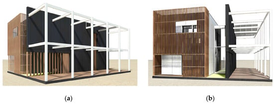
Figure 10.
The virtual pilot building. Front view (a) and lateral view (b).
Its dimensions are about 5.2 m × 15 m by about 8 m high. The second block is deliberately only realised to demonstrate the structure for demonstration purposes, making the structural grid and the fibreglass construction system visible. The access to the building is between the two bodies.
4.1. The Building Process
To ensure the success of the IDP, digital technologies were applied using the building information modelling (BIM) methodology. We also decided to organise the methodology using a BIM execution plan (BEP) activities list.
Through the BIM, the parametric virtual model of the pilot building is elaborated and all the extractable technical information are carried with it, while the BEP defines the programmed objectives, the survey, and the directives of graphic restitution for the design at each level.
To monitor each phase of the building process, from the beginning to the verification and control operations, a rigorous organisation of work in the digital field was developed, starting from the needs defined by the project and from the contractual content.
The BEP list represents the guidelines to create the conditions for the buildings to be brought into compliance with the overall regulations—static and functional (acoustics, and lighting included), favouring the energy–environmental targets.
The BEP organises the digital tools, making them interact and making them available to facilitate collaboration between the numerous subjects involved in the process.
The BEP content can be summarised in a list, as follows:
- Identification of the main goals, including changing the temporary emergency house into a permanent house;
- Previous skills and experience of the team in modular systems, including a structural engineer with experience with FRPs;
- Survey/analysis of the laboratory tests;
- BIM software to be used during the project and its versions;
- Objectives and uses of information models, how data are shared, including exchange files for acoustic prediction analysis;
- Information modelling and definition of the level of information need (LOIN);
- Definition of the information documents;
- Compliance with standards including acoustics;
- Operational details of the management with the identification of the BIM specialists, coordinators, and managers;
- Storage methods and delivery strategies to optimise the construction time;
- Contextual management of the collaborative design phase;
- The construction and the maintenance.
The work team identified its own roles in the BEP, means, methods, and IT solutions, and indications on the definitions of level of definition/development (LOD) and level of information need (LOIN) and on the management of the information in BIM were clarified.
Because FRP structures have a strong influence on a multitude of the involved disciplines in the project and a strong impact on the structural system itself, an integrated structural process model (ISPM) for FRPs was added, and FRP profiles needed to be modelled first, becoming “loadable” objects in the project (a system database is still lacking).
To include acoustic, structural, and energy analysis in the process, the BIM’s interoperability was analysed, and the Industry Foundation Classes (IFC) format was taken into consideration.
In the case study, the analysis and assessment of thermal and acoustic performance aimed to achieve a nearly zero-energy building and to comply with the Italian DPCM 5.12.97 (category A) [62].
The calculation and verification of the structures were performed with specific software (such as SISMICAD for example) according to the Eurocodes or the technical standards, with a module for the evaluation of generic materials.
For energy solutions, simulations followed both the standard models of the construction country, in Italy CENED 1.1.5 (Certificazione energetica degli edifici, energy building certification), and the static (THERM 7.6.01) and dynamic regime models (TRNSYS 18).
4.2. Project Description
The single block consists of two units, one on each floor, in which there are two rooms, a living space and a sleeping space, divided by a service block containing the bathroom and a wall equipped with fixtures and services intended to create a kitchen.
The interior space is designed for testing and verifying the indoor microclimate conditions in relation to energy commitment under normal use by potential inhabitants of the housing units.
In the module basement (between ground level and the floor frame supported by the piles), rainwater storage, electrical storage, and a container with chemical solvents to accommodate the sanitary drains for the first emergency phase are inserted (in the absence of sewer drains), making it possible to prototype a ZEB building in the future [38].
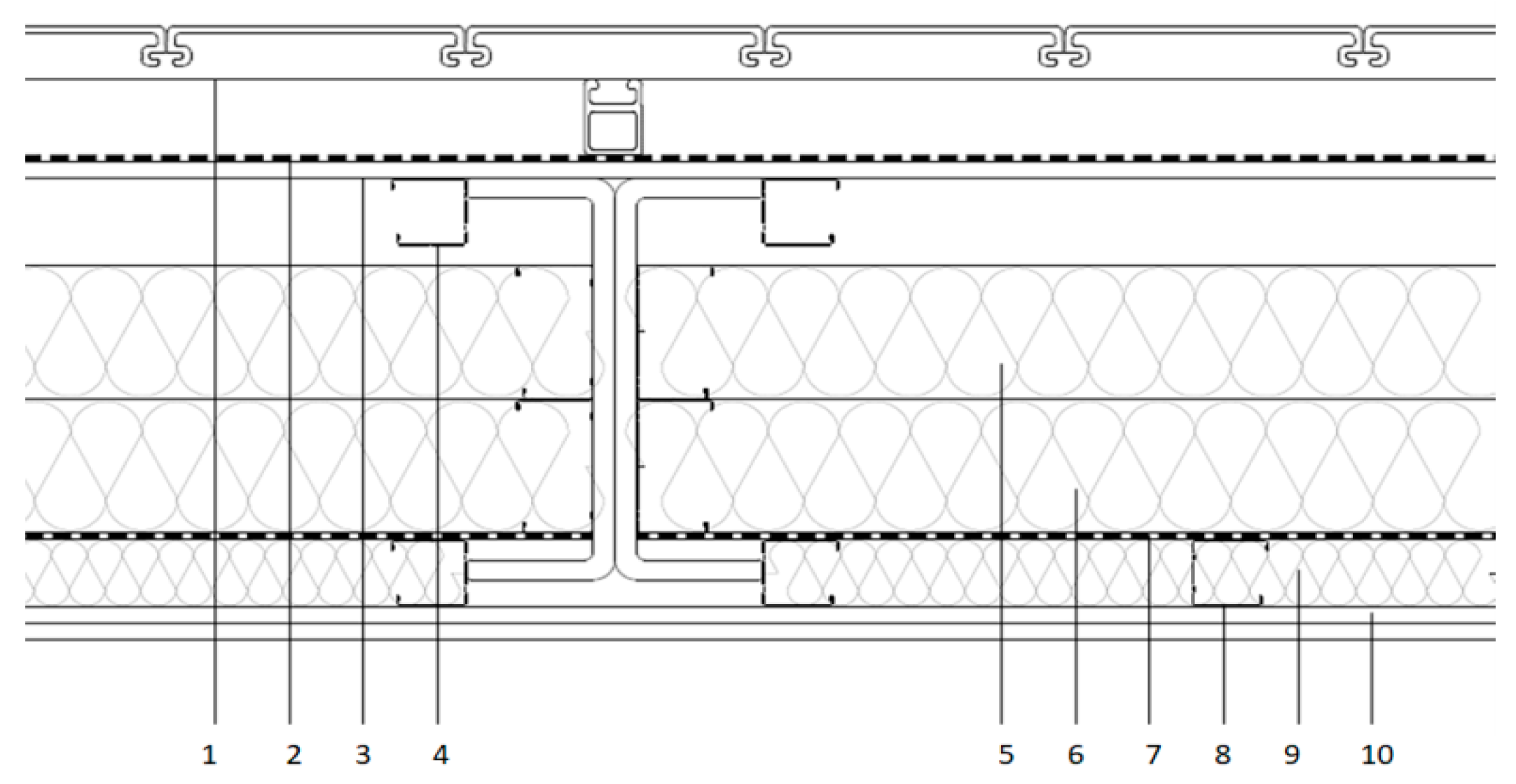
Vertical and horizontal partitions are designed following the technologies suggested for dry construction systems. Façades are made with a multilayer drywall system and are clad externally with FRP panels to ensure low transmittance, high durability, and weather resistance. Window frames include double chambers with external shading systems. The main façade cladding is presented in the figure below (Figure 11).
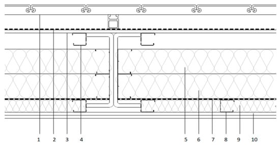
Figure 11.
Main façade cladding: 1.80 mm fibreglass facade system; 2. high-transpiration membrane in polypropylene and polyurethane; 3. 12.5 mm fibre cement board; 4. 50 mm plasterboard structure and galvanised steel profiles; 5. 100 mm rock wool panel, 80 kg/m3 density; 6. 100 mm rock wool panel, 80 kg/m3 density; 7. vapor barrier; 8. 50 mm plasterboard structure in galvanised steel profiles; 9. rock wool, 40 kg/m3 density; 10. double 12.5 mm fibre cement board.
The values of the Apparent Sound Reduction Index R’w and the Transmittance U for the other main components are shown in Table 1.

Table 1.
Transmittance U and Apparent Sound Reduction Index for the main unit’s perimeter partitions.
The building is equipped with an efficient air-to-air heat recovery system, an air-to-water heat pump (electrical power absorption of 2.2 kW) for domestic hot water production, and 18 modules of photovoltaic panels over the roof surface with a power of 5.8 kWp. The high thermal insulation of the building envelope, the optimisation of solar heat gains, and the other passive heating measures contribute to reducing the total primary energy consumption to 50.54 kWh/m2. Considering the properties of the building and the plant system’s characteristics, much of the energy needed comes from renewable sources, off the distribution grid. Thanks to its performance, the building can be defined as a nearly zero-energy building [14,41,42]. The building will be monitored over the next few years to evaluate its resilience in terms of energy balance in order to evaluate how climate change will influence the performance.
4.3. Structures and Laboratory Tests
Firstly, it was verified that FRPs can be used with many foundation typologies. For the pilot building, the foundation system is designed in helical steel piles, driven into the ground, that carry a self-supporting FRP frame. All supporting systems are made of FRP beams and columns.
Both buildings feature seven portal frames, placed at a distance of 2.30 m apart, made from coupled “C” and double “T” sections. Connections between the pultruded profiles are made using 8 mm thick steel plates and 8.8-strength class bolts.
The two building structures are connected by a steel staircase with elastic junctions, so that displacements induced by external actions (wind and earthquake) do not produce significant effects between the building bodies.
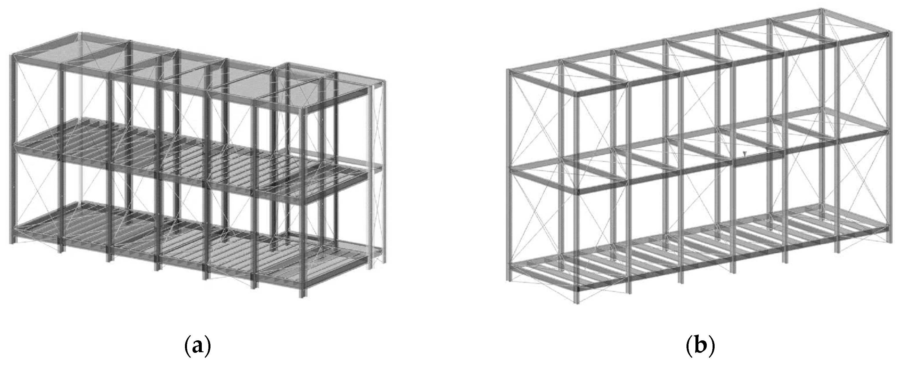
The main columns and beams, which make up the portals of the load-bearing structure, are composed of paired pultruded “C” profiles with the dimensions 300 × 100 × 15 mm, while those of Building 2 are composed of paired “C” profiles with the dimensions 200 × 60 × 10 mm. The secondary structure, which makes up the floor slabs, is made using 200 × 100 × 10 mm double “T” profiles, placed at variable spacing, depending on the calculation span, from 46 cm to 77 cm (Figure 12).

Figure 12.
Structures. Building 1 (a) and Building 2 (b).
The total weight of Building 1, considering all the structural and architectural elements to complete the construction, is equal to 634.24 kN (corresponding to a uniformly distributed surface load of 4.01 kN/m2 per floor), while that of Building 2 is 57.87 kN (corresponding to 1.01 kN/m2 per floor). Focusing on the weight of Building 1, it is simple to establish that the total weight of the building (structure + cladding + floors) is equal to that of two 16 cm thick reinforced concrete slabs.
The lightness of these materials, combined with the mechanical properties of the pultruded profiles, confirms that their use is interesting for the construction of structures in areas of high seismicity because, since the seismic force depends on the mass of the structure and its inertial characteristics, the intensity of these forces takes on modest values. Therefore, it is the wind actions that must be considered by the designer, who must define the structure so that the displacements are such that they ensure adequate comfort for the users of the building. The lightness of the materials was also considered for the façades, combined with their thermal and acoustic properties. To complete the commissioning, tension tests on the composite material were required.
4.4. Laboratory Tests
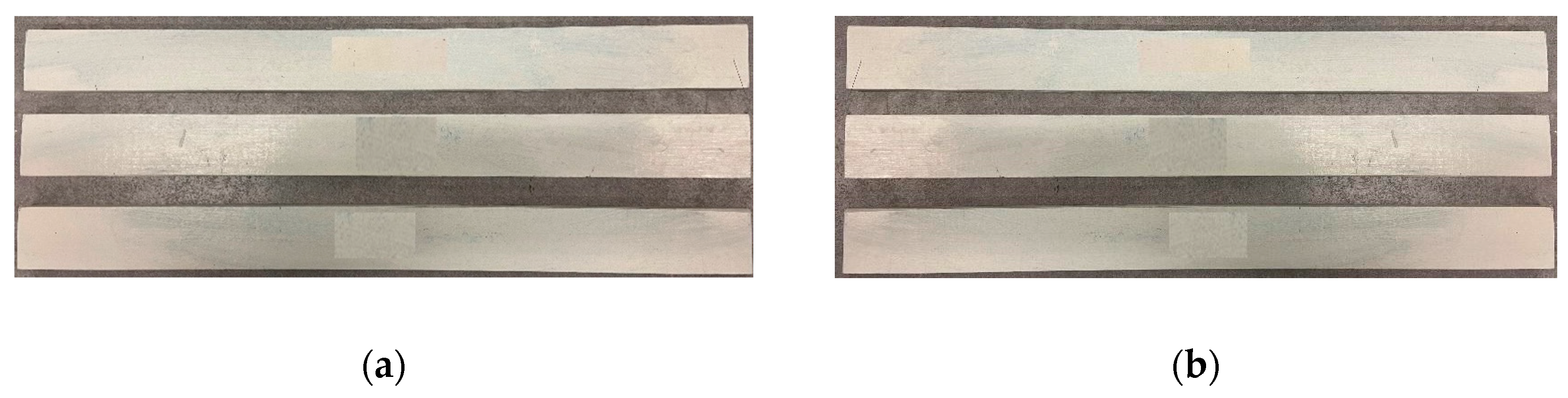
Tension tests on the composite material were performed following the standard UNI EN ISO 527-472/2 [63,64]. The profiles samples were obtained with pultrusion technology. The larger dimension of the specimens (length = 250 mm or 500 mm) was oriented according to the longitudinal direction of the profiles, coinciding with the pultrusion direction (the axis according to which the production of the material proceeds).
Two different prisms were tested: five prismatic samples in FRPs with the nominal dimensions 250 × 25 × 10 mm and five prismatic samples in FRPs with the nominal dimensions 500 × 50 × 15 mm (Figure 13).
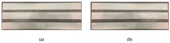
Figure 13.
GFRP samples: nominal dimensions 250 × 25 × 10 mm (a); nominal dimensions 500 × 50 × 15 mm (b).
Before the test, the specimens were kept for a minimum of 19 h in an air-conditioned environment at a temperature of 23 ± 2 °C and a RH of 50 ± 10%.
The test was carried out in the same environmental conditions to determine the values of the tension elasticity modulus and the maximum stress.
For the 10 mm thick specimens, a 250 kN testing machine was used; for the 15 mm thick specimens, a 500 kN testing machine was used instead.
To align the sample with the vertical axis of the traction machine, a metal clamp was positioned, having the function of placing the specimen in contact with the traction machine.
The specimens were gripped between the jaws of the testing machine over a length of 75 mm for the 10 mm thick samples and 80 mm for the 15 mm thick ones, leaving an initial distance between the grips of 100 mm for the former samples and 340 mm for the latter.
The samples were instrumented in the central area using a strain gauge with a measuring base L0 equal to 50 mm for the 10 mm thick samples and L0 equal to 100 mm for the 15 mm thick samples, up to a deformation value corresponding to approximately 50% of the maximum expected load in order to avoid breakage.
For the 10 mm thick samples, a preload of approximately 0.05 kN was given, while the 15 mm thick samples were given a preload of approximately 0.1 kN.
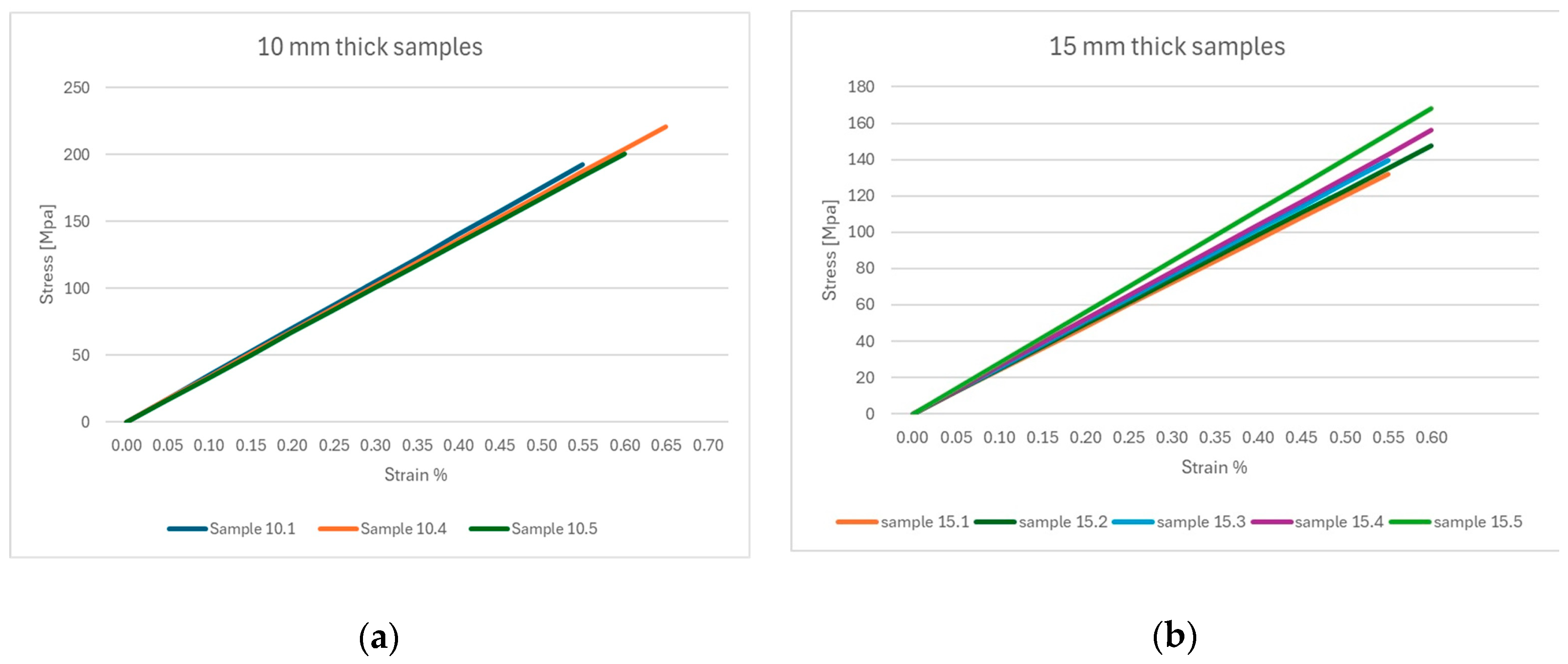
The evaluation of the elastic modulus was carried out considering the linear regression of the stress–strain curve within the interval 0.1 εr and 0.4 εr, where εr coincides with the deformation at the maximum load (Figure 14).

Figure 14.
Stress–strain curve: the 10 mm thick samples (a); the 15 mm thick samples (b).
The deformation at the maximum tension load (εr) was calculated by assuming the linear trend of the stress–strain diagram and dividing the stress by the elastic modulus.
4.5. The Construction Phase
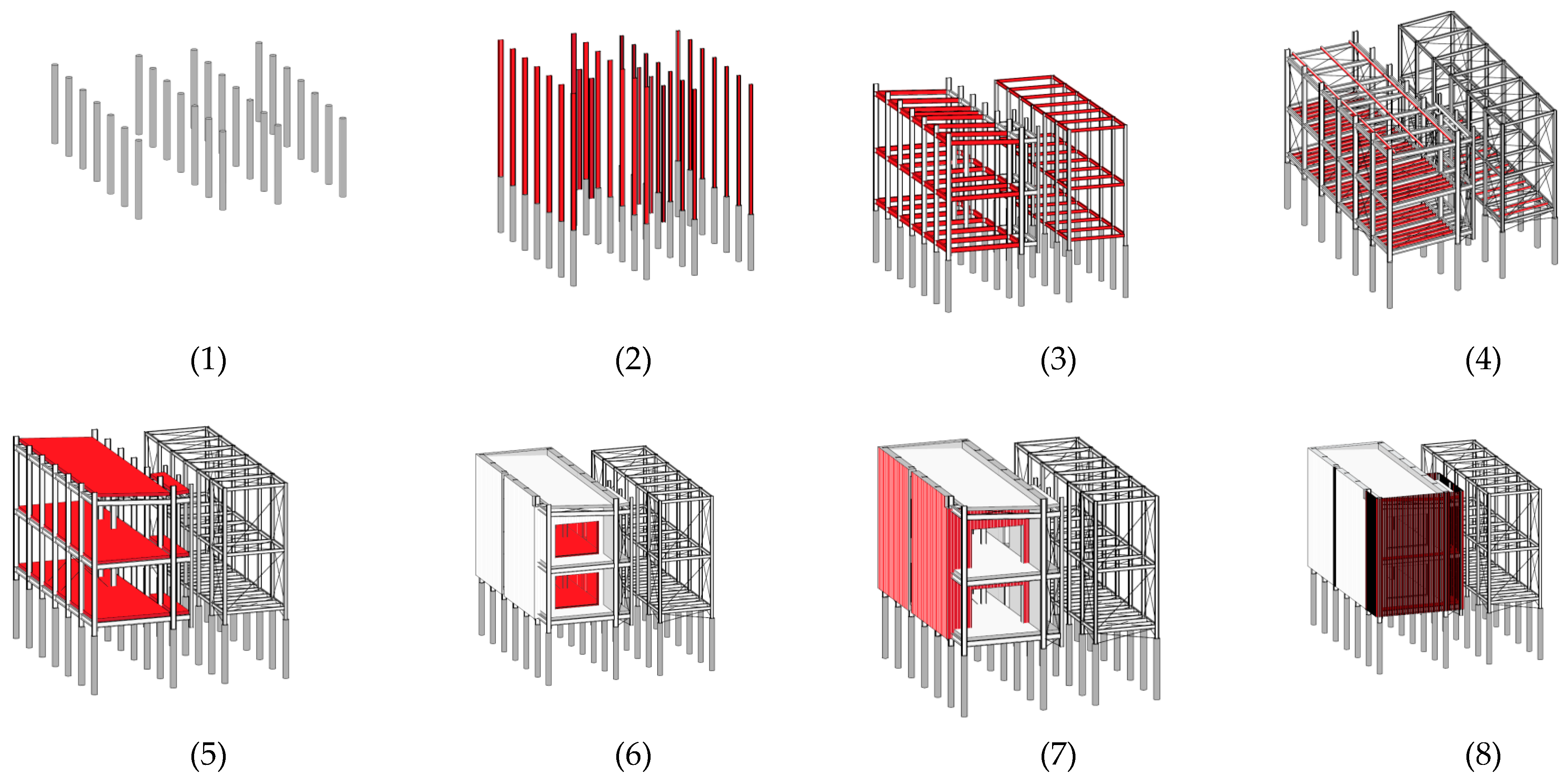
Our research aimed to renew traditional models of construction management and the tools used, laying the foundations and principles for future application through digital technologies and systems, removing constraints and obstacles that make the process construction difficult to manage. Unfortunately, the construction company involved in the pilot unit construction preferred to operate the time variable traditionally, using the tool of the so-called “chronoprogram” in the construction process, arguing that no professionals were prepared for the new methodology identified in the integrated project development (4D modelling). The construction phase was subdivided into nine steps (Figure 15), including eight to complete the passive unit (Figure 16) and one to add the active unit systems. From step 2 to step 5, one month was necessary considering two workers and one construction site vehicle. For the entire construction process, about 120 days was required, including the installation of the energy and electrical equipment for commissioning (Figure 17).

Figure 15.
Passive unit assembly steps: (1). foundations; (2). vertical structure; (3). horizontal structure; (4). secondary vertical and horizontal structure; (5). horizontal Slabs; (6). envelope; (7). windows; (8). sunshading.

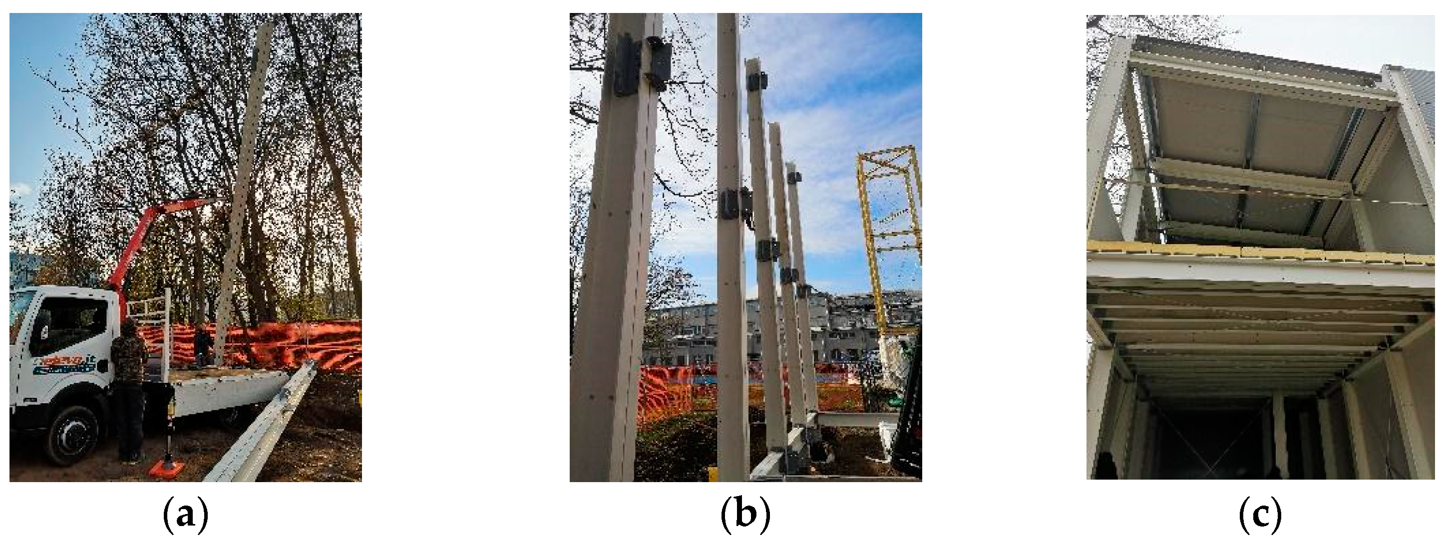
Figure 16.
The pilot building construction: vertical structure (a,b) and structures completed (c).
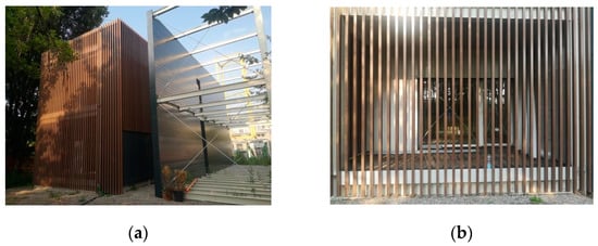
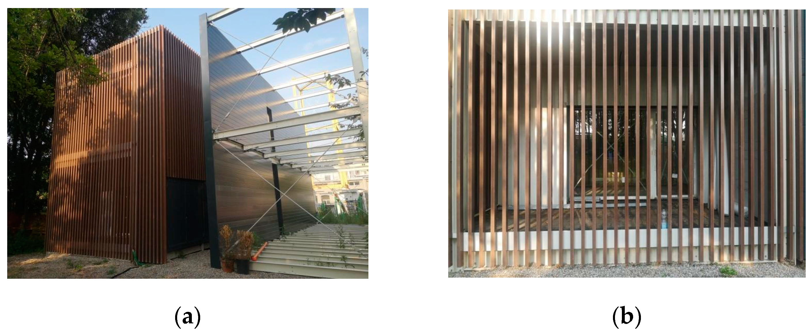
Figure 17.
The pilot building: the whole building (a) and the façade detail (b).
5. Results and Discussion
During the initial development, from a basic cell to larger modular housing units, the basic FRP portal frame module was established. Each portal was spaced 2.30 m apart, based on structural analysis, regardless of the foundation conditions. This module design, with 2.30 m spacing, positively impacted the technical solutions for walls, partitions, and cladding. Numerous benefits were observed with the portal spacing. The distance was sufficient to accommodate house openings like windows, doors, and balconies, allowing for flexibility in design and customisation while complying with lighting standards. It was compatible with the energy unit, not interfering with installation and maintenance, and suitable for nearly zero-energy building basic cells, facilitating connections to energy networks and necessary emergency activities. The spacing also aligned well with general plant design and installations.
The portal distance was compatible with the Energy Unit, not interfering with installation and maintenance activities. It was also well matched for the realisation of a single nearly zero-energy building basic cell, with predispositions for connections to energy networks and for accommodating different activities that are necessary in an emergency. It was also observed that the structure’s distance was compatible with plants’ design and installations in general.
The portal distribution allowed the construction of two-story modular systems, but further research is needed to add more floors and connect them to FRP stairs and foundations. The spacing of vertical structures determined the dimensions of the perimeter cladding panels, which were space-saving and easy to transport and assemble. Five main loadable families were identified for the base unit:
- Structural elements (FRP profiles);
- Vertical partitions;
- Horizontal partitions;
- Plants;
- Lighting equipment.
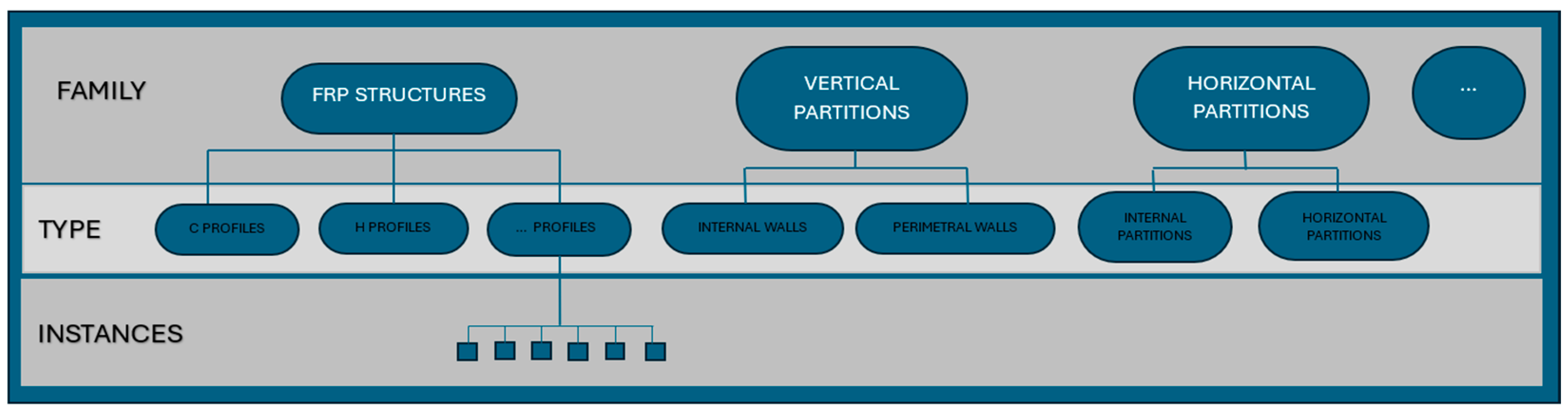
Loadable families, or standard component families, were selected because they include commonly purchased, delivered, and installed building components. They are user-defined and can be created and modified in the authoring software based on project requirements (Figure 18); they were developed to suit the climatic conditions and project standards. Various facades and roofs were designed for both emergency and permanent buildings, customised for location and use. The BIM methodology simplified their evaluation for optimising the building process.
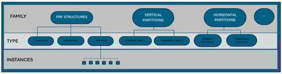
Figure 18.
Loadable family workflow.
Unlike system families, loadable families can be saved as external RFA files and loaded into projects as needed. This speeds up the modelling process, allowing experts to directly import available components into ongoing projects.
Due to their highly customisable nature, loadable families can include various types supported by type catalogues, which help to develop a standardised and industrialised design process for customisable modular housing systems in FRP.
For the basic module, a database of loadable families containing specific attributes (e.g., structural properties, sound reduction index Rw, impact sound reduction index Lw, thermal properties like Transmittance U) can be uploaded in real time. This advances the FRP modular housing system toward Industry 4.0.
The implementation of loadable families in the BIM methodology marks the beginning of developing a new supply chain model. It aims to create an FRP housing product that can penetrate the market, promoting multifunctionality in modular systems to quickly and effectively meet contemporary living needs.
This research aims to highlight the advantages of using fibreglass, such as the ease of its installation and reuse and the short construction time. An early-stage comparison between the time schedules for building a traditional house and the pilot unit is evaluated.
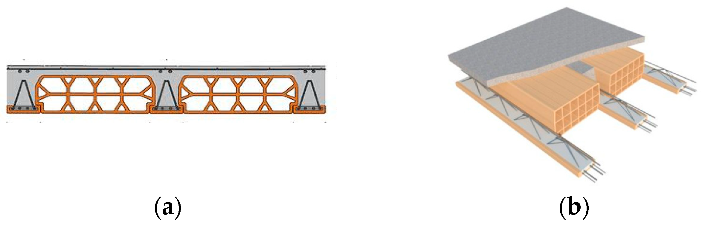
A traditional Italian house was designed with the same geometry and shape as the completed basic cell, featuring a structure with concrete columns and slabs made of cast-in-place beams and clay blocks (Figure 19).

Figure 19.
Horizontal slabs made of cast in place beams and clay blocks.Vertical section (a), 3d view (b).
Concrete columns were placed 4.6 m apart, using the same foundations and cladding system as the modular housing to compare the two construction types. The plants and energy units were also the same in both projects. For the traditional house, the construction process (phases 2–5 of the pilot unit) was organised as follows:
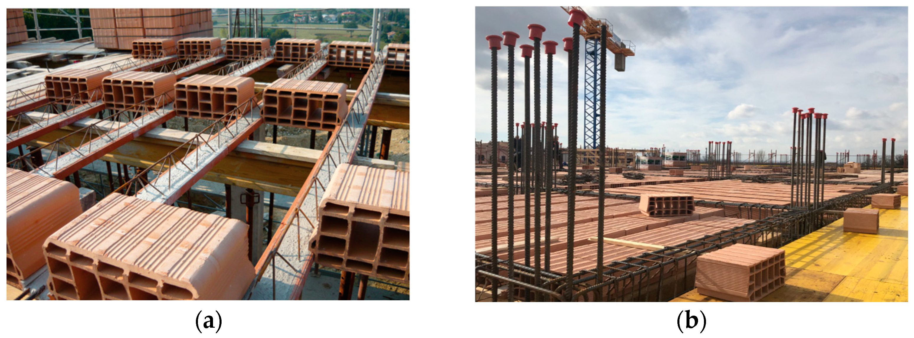
- Temporary scaffolding to build the base level, form the horizontal slab, and prepare steel bars for entry-level columns (Figure 20);
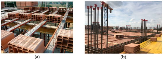 Figure 20. Temporary scaffolding for building the base level and forming the horizontal slab (a). Example of horizontal slab and steel bar preparation for columns (b).
 - Concrete pouring of the base level and columns;
- Temporary scaffolding to build the first level, form the horizontal slab, and prepare steel bars for first-level columns;
- Concrete pouring of the first level and columns;
- Temporary scaffolding to build the final horizontal level;
- Concrete pouring of the final horizontal level.
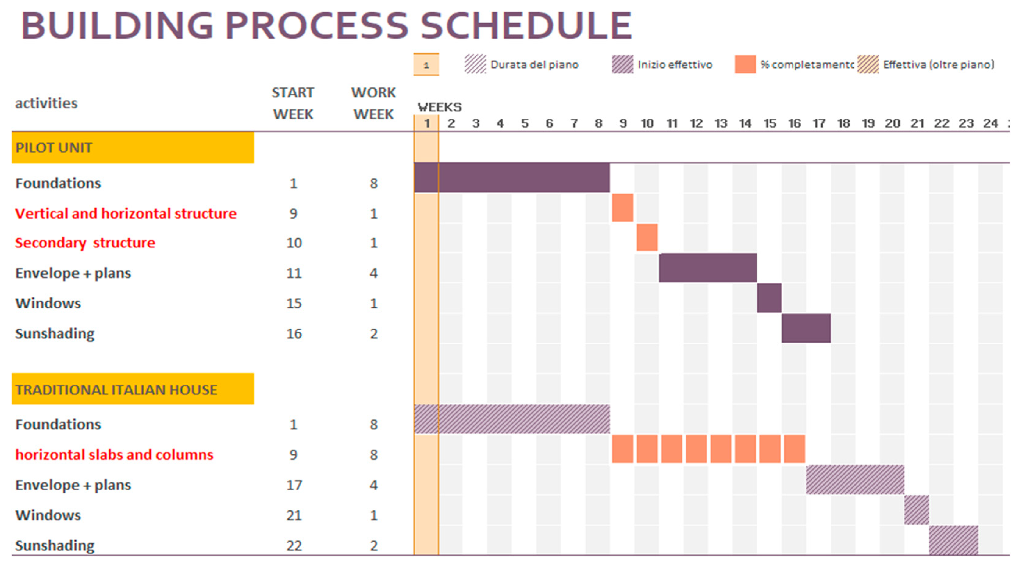
To complete the structure with horizontal slabs and compare it to steps 2–5 of the pilot unit, the construction company estimated a construction time of two months due to concrete curing, different instruments, and security requirements. The traditional process was estimated to take four times longer than the pilot unit, with reduced on-site construction costs for the pilot unit without compromising assembly precision. The time and cost differences were identified, with the pilot unit taking one month to complete phases 2 to 5, and approximately 2 weeks for the double-floor building cell.
The number of people involved in achieving the completed structure with horizontal slabs so that it was comparable with steps 2 to 5 of the pilot unit was estimated to be equal to six per day, including the scaffolding assembly and disassembly, which were not necessary for the pilot unit. The construction site vehicles were comparable with those of the modular system.
This early-stage evaluation showed that the daily working costs on site were tripled for a period at least four times longer than that of the modular FRP house (steps 2 to 5, Figure 21).
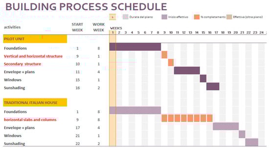
Figure 21.
Building construction program.
While the construction time and associated costs are clearly reduced for building modular FRP housing, cost variations for FRP structures can occur based on the location of the emergency intervention or permanent settlement and the proximity to the nearest or most competitive FRP supplier.
In this case study, FRP structures were about 20% more expensive than those of a traditional house. However, the overall construction process of the pilot project was approximately 12% cheaper than traditional construction. Thus, achieving economies of scale is crucial for introducing the FRP modular system to the market. Manufacturing costs could be significantly reduced through serial and modular production, while fast assembly would ensure shorter on-site construction time without compromising structural stiffness or thermo-acoustic performance.
6. Conclusions
Through the use of an integrated design process for a virtual modular housing system and new technologies applied to a built pilot house, it was possible to ascertain numerous advantages of using FRP elements in buildings.
The FRP structural frames are easily integrated into dry construction systems both during the design phase, as part of the integrated project, and during the on-site works, minimising the construction time of the building.
The portal distance recommended by structural analysis for the modular system positively influenced the technical solutions for walls, partitions, and cladding, while maintaining flexibility in architectural design and potential customisations.
The low specific weight of the material facilitates many steps in the process, from production to transportation and installation, and the versatility of the structure also promotes its use in areas of high seismic risk, as suggested by the literature.
It has been observed that FRPs can be used with many foundation typologies, which can vary according to the morphology of the land on which the building stands and can be combined with other metal structures. FRP panels can be applied to façade systems. Both of these topics could be studied more thoroughly, becoming a research theme for the future.
FRPs integrate with the optimisation of acoustic requirements and act synergistically with nZEB building energy goals by minimising thermal bridges near structural portals due to their low thermal transmittance.
New skills are acquired related to the specific type of construction considered (use of lightweight, easily workable, and pre-assembled materials and the identification of organisational and logistical criteria).
The design of the prototype enabled the integration of established knowledge and solutions in the area of new technologies, in the area of materials, especially in the area of innovations in digital applications, and enhanced skills for adapting building units to different environmental conditions, including seismic requirements. To achieve a successful outcome, an IDP, supported by a BIM methodology, has been found to be one of the most important supporting factors. Digitisation, in fact, has been considered a significant innovation step in the architecture, engineering and construction (AEC) sector, and would also be helpful for introducing the use of FRP systems in the built environment.
The implementation of loadable families in the BIM methodology has initiated the development of a new supply chain model. This focuses on creating an FRP housing product that can penetrate the market and promote multifunctionality in modular systems, effectively meeting contemporary living needs.
Due to their customisable nature, loadable families can include many types supported by type catalogues, which help to standardise and industrialise the design process for modular housing systems. These can be updated in real time with new research and technological solutions. Manufacturing costs could be significantly reduced through serial and modular production, while fast assembly would ensure shorter on-site construction times without compromising structural stiffness or thermo-acoustic performance.
FRP loadable families can also be applied to building renovation, with specific and targeted interventions; to buildings potentially susceptible to collapse; to the design of buildings that are in boundary weathering events; and to the evaluation of integrated building–user behaviour, with reference to low-energy, NZEB and zero-energy buildings (ZEBs) in innovative materials.
In general, our modular housing system using FRPs has been proven to be capable of entering the building and real estate market in the future, and allows for “customised” buildings, characterised by innovative materials and structural components that can be easily integrated using the proposed Bim methodology, achieving high indoor comfort, excellent energy quality, flexibility, recyclability, and risk reduction in the various construction phases.
Further research suggests developing a digital twin (DT) using sensors to control energy savings in real time, connected with BIM. Additionally, exchanging sample Industry Foundation Classes (IFC) 4D BIM models with Gantt charts can further optimise the construction process.
Author Contributions
Conceptualisation, M.C.; methodology, M.C.; software, M.C. and G.I.; validation, M.C.; formal analysis, M.C.; investigation, M.C.; resources, M.C. and G.I.; data curation, M.C.; writing—original draft preparation, M.C.; writing—review and editing, M.C.; visualisation, M.C. and G.I.; supervision, M.C.; project administration, G.I.; funding acquisition, G.I. All authors have read and agreed to the published version of the manuscript.
Funding
Bio-Acouis project, funding through the European Union’s Horizon 2021 Research and Innovation Programme for the MSCA Staff Exchanges program. Grant No. 101086325.
Data Availability Statement
Data are unavailable due to privacy reasons.
Conflicts of Interest
The authors declare no conflicts of interest.
References
- Deng, S.; Wang, R.; Dai, Y. How to evaluate performance of net zero energy building—A literature research. Energy 2014, 71, 1–16. [Google Scholar] [CrossRef]
- Lopeza, D.; Froesea, T.M. Analysis of costs and benefits of panelized and modular prefabricated homes. Procedia Eng. 2016, 145, 1291–1297. [Google Scholar] [CrossRef]
- Siggner, R. Modular Housing: Benefits, Challenges and Lessons Learned; BC Housing: Burnaby, BC, Canada, 2011. [Google Scholar]
- The Canadian Timber Company. What Is Panelized Construction? The Canadian Timber Company: Hamilton, ON, Canada, 2007. Available online: http://www.canadiantimber.ca/build_panelized.html (accessed on 20 December 2015).
- Kamali, M.; Hewage, K.; Sadiq, R. Economic sustainability benchmarking of modular homes: A life cycle thinking approach. J. Clean. Prod. 2022, 348, 131290. [Google Scholar] [CrossRef]
- Kim, D. Preliminary Life Cycle Analysis of Modular and Conventional Housing in Benton Harbor. Master’s Thesis, University of Michigan, Ann Arbor, MI, USA, 2008. [Google Scholar]
- Kamali, M.; Hewage, K. Life cycle performance of modular buildings: A critical review. Renew. Sustain. Energy Rev. 2016, 62, 1171–1183. [Google Scholar] [CrossRef]
- Kamali, M.; Hewage, K. Sustainability performance assessment: A life cycle based framework for modular buildings. In Proceedings of the 6th International Construction Specialty Conference (CSCE/CRC 2017), Vancouver, BC, Canada, 31 May 2017. [Google Scholar]
- Kamali, M.; Hewage, K. Development of performance criteria for sustainability evaluation of modular versus conventional construction methods. J. Clean. Prod. 2017, 142, 3592–3606. [Google Scholar] [CrossRef]
- Kamali, M.; Hewage, K. Life cycle sustainability performance assessment framework for residential modular buildings: Aggregated sustainability indices. Build. Environ. 2018, 138, 21–41. [Google Scholar] [CrossRef]
- Kamali, M.; Hewage, K. Conventional versus modular construction methods: A comparative cradle-to-gate LCA for residential buildings. Energy Build. 2019, 204, 109479. [Google Scholar] [CrossRef]
- Bashawri, A.; Garrity, S.; Moodley, K. An overview of the design of disaster relief. Procedia Econ. Financ. 2014, 18, 924–931. [Google Scholar] [CrossRef]
- Félix, D.; Branco, J.M.; Feio, A. Temporary housing after disasters: A state of the art survey. Habitat Int. 2013, 40, 136–141. [Google Scholar] [CrossRef]
- Reider, R.; Meir, I.A. Comparing the energy implications of FRP and concrete residential construction in a hot arid climate. Energy Build. 2019, 186, 98–107. [Google Scholar] [CrossRef]
- Qureshi, J. A Review of Fibre Reinforced Polymer Structures. Fibers 2022, 10, 27. [Google Scholar] [CrossRef]
- Zafari, B. Startlink Building System and Connections for Fibre Reinforced Polymer Structures. Ph.D. Thesis, University of Warwick, Coventry, UK, 2012. [Google Scholar]
- Chao, F.; Wenxiu, L.; Muhammad, A.; Lee, C. Environmental evaluation of FRP in UK highway bridge deck replacement applications based on a comparative LCA study. Adv. Mater. Res. 2012, 374–377, 43–48. [Google Scholar]
- Daniel, G. A composite bridge is favoured by quantifying ecological impact. Struct. Eng. Int. J. Int. Assoc. Bridge Struct. Eng. (IABSE) 2010, 20, 385–391. [Google Scholar] [CrossRef]
- Shi, J.; Kato, J.; Bao, L.M.; Kemmochi, K. The mechanical property of recycled fiber reinforced polymer composites by superheated steam. Appl. Mech. Mater. 2013, 339, 687–690. [Google Scholar] [CrossRef]
- Leccese, F.; Rocca, M.; Salvadori, G.; Belloni, E.; Buratti, C. Towards a holistic approach to indoor environmental quality assessment: Weighting schemes to combine effects of multiple environmental factors. Energy Build. 2021, 245, 111056. [Google Scholar] [CrossRef]
- Liu, T.; Feng, P.; Bai, Y.; Bai, S.; Yang, J.-Q.; Zhao, F. Flexural performance of curved-pultruded GFRP arch beams subjected to varying boundary conditions. Eng. Struct. 2024, 308, 117962. [Google Scholar] [CrossRef]
- Wang, C.; Guo, L.; Xia, Y.; Zhang, C.; Sang, X.; Xu, C.; Zhu, G.; Ji, H.; Zhao, P.; Fang, H.; et al. Flexural performance and damage evolution of multiple fiberglass-reinforced UV-CIPP composite materials—A view from mechanics and energy release. J. Mater. Res. Technol. 2024, 29, 3317–3339. [Google Scholar] [CrossRef]
- Qureshi, J.; Nadir, Y.; John, S.K. Bolted and bonded FRP beam-column joints with semi-rigid end conditions. Compos. Struct. 2020, 247, 112500. [Google Scholar] [CrossRef]
- Qureshi, J.; Nadir, Y.; John, S.K. Cyclic Response of Bolted and Hybrid Pultruded FRP Beam-Column Joints between I-Shaped Sections. Fibers 2021, 9, 66. [Google Scholar] [CrossRef]
- Imperadori, M.; Salvalai, G.; Pusceddu, C. Air shelter house technology and its application to shelter units: The case of scaffold house and cardboard shelter installations. Procedia Econ. Financ. 2014, 18, 552–559. [Google Scholar] [CrossRef]
- Guo, W.; Qiao, X.; Huang, Y.; Fang, M.; Han, X. Study on energy saving effect of heat-reflective insulation coating on envelopes in the hot summer and cold winter zone. Energy Build. 2012, 50, 196–203. [Google Scholar] [CrossRef]
- Borge-Diez, D.; Colmenar-Santos, A.; Mur-Pérez, F.; Castro-Gil, M. Impact of passive techniques and clean conditioning systems on comfort and economic feasibility in low-cost shelters. Energy Build. 2013, 62, 414–426. [Google Scholar] [CrossRef]
- Hosseini, S.A.; de la Fuente, A.; Pons, O. Multi-criteria decision-making method for assessing the sustainability of post-disaster temporary housing units technologies: A case study in Bam, 2003. Sustain. Cities Soc. 2016, 20, 38–51. [Google Scholar] [CrossRef]
- Atmaca, A.; Atmaca, N. Comparative life cycle energy and cost analysis of post-disaster temporary housings. Appl. Energy 2016, 171, 429–443. [Google Scholar] [CrossRef]
- McIntosh, J. The Implications of Post Disaster Recovery for Affordable Housing; IntechOpen: London, UK, 2013. [Google Scholar]
- Song, Y.; Mithraratne, N.; Zhang, H. Life-time performance of post-disaster temporary housing: A case study in Nanjing. Energy Build. 2016, 128, 394–404. [Google Scholar] [CrossRef]
- De Fazio, D.; Boccarusso, L.; Formisano, A.; Viscusi, A.; Durante, M. A Review on the Recycling Technologies of Fibre-Reinforced Plastic (FRP) Materials Used in Industrial Fields. J. Mar. Sci. Eng. 2023, 11, 851. [Google Scholar] [CrossRef]
- Boscato, G.; Casalegno, C.; Russo, S. Design of FRP Structures in Seismic Zone; Manual by Top Glass, S.p.A. and IUAV University of Venice: Venice, Italy, 2015. [Google Scholar]
- Ascione, L.; Gutierrez, E.; Dimova, S.; Pinto, A.; Denton, S. Prospect for New Guidance in the Design of FRP. Support to the Implementation and Further Development of the Eurocodes; JRC Science and Policy Report JRC99714, EUR 27666 EN; European Union: Luxembourg, 2016; p. 171. ISBN 978-92-79-54225-1. [Google Scholar] [CrossRef]
- Kollar, L.P. Local Buckling of Fibre Reinforced Plastic Composite Structural Members with Open and Closed Cross Section. J. Struct. Eng. ASCE 2003, 129, 1503–1513. [Google Scholar] [CrossRef]
- Tarjan, G.; Sapkas, A.; Kollar, L.P. Stability Analysis of Long Composite Plates with Restrained Edges Subjected to Shear and Linearly Varying Loads. J. Reinf. Plast. Compos. 2010, 29, 1386–1398. [Google Scholar] [CrossRef]
- Woltman, G.; Noel, M.; Fam, A. Experimental and numerical investigations of thermal properties of insulated concrete sandwich panels with fiberglass shear connectors. Energy Build. 2017, 145, 22–31. [Google Scholar] [CrossRef]
- Sofi, S.; Ferraro, M.; Antonucci, V. LCA propedeutica all’ottenimento della dichiarazione ambientale di prodotto di un modulo abitativo prefabbricato con elementi pultrusi fibrorinforzati. In Proceedings of the VIII Convegno della rete Italiana LCA, Firenze, Italy, 19–20 June 2014. [Google Scholar]
- Lehmann, S. Low carbon construction systems using prefabricated engineered solid wood panels for urban infill to significantly reduce greenhouse gas emissions. Sustain. Cities Soc. 2013, 6, 57–67. [Google Scholar] [CrossRef]
- Theodosiou, T.G.; Tsikaloudaki, A.G.; Kontoleon, K.J.; Bikas, D.K. Thermal bridging analysis on cladding systems for building facades. Energy Build. 2015, 109, 377–384. [Google Scholar] [CrossRef]
- Pittaua, F.; Malighettia, L.E.; Iannacconea, G.; Maseraa, G. Prefabrication as large-scale efficient strategy for the energy retrofit of the housing stock: An Italian case study. Procedia Eng. 2017, 180, 1160–1169. [Google Scholar] [CrossRef]
- Erten, D.; Kılkış, B. How can green building certification systems cope with the era of climate emergency and pandemics? Energy Build. 2022, 256, 111750. [Google Scholar] [CrossRef]
- Mannino, A.; Dejaco, M.C.; Re Cecconi, F. Building Information Modelling and Internet of Things Integration for Facility Management—Literature Review and Future Needs. Appl. Sci. 2021, 11, 3062. [Google Scholar] [CrossRef]
- Haghsheno, S.; Deubel, M.; Spenner, L. Identification and description of relevant digital technologies for the construction industry. Bauingenieur 2019, 94, 45–55. [Google Scholar] [CrossRef]
- Hossain, M.A.; Nadeem, A. Towards digitising the construction industry: State of the art of construction 4.0. In Proceedings of the ISEC 10: Interdependence between Structural Engineering and Construction Management, Chicago, IL, USA, 20–25 May 2019; pp. 1–6. [Google Scholar]
- Cumo, F.; Sferra, A.S.; Pennacchia, E. Patrimonio edilizio della “Sapienza”: Strumenti digitali integrati per il progetto esecutivo. TECHNE J. Technol. Archit. Environ. 2019, 18, 191–198. [Google Scholar]
- Maltese, S.; Tagliabue, L.C.; Re Cecconi, F.; Pasini, D.; Manfren, M.; Ciribini, A.L.C. Sustainability Assessment through Green BIM for Environmental, Social and Economic Efficiency. Procedia Eng. 2017, 180, 520–530. [Google Scholar] [CrossRef]
- Elnabawi, M. Building information modelling-based building energy modelling: Investigation of interoperability and simulation results. Front. Built Environ. 2020, 6, 573971. [Google Scholar] [CrossRef]
- Garcia, E.G.; Zhu, Z. Interoperability from building design to building energy modeling. J. Build. Eng. 2015, 1, 33–41. [Google Scholar] [CrossRef]
- Sušnik, M.; Tagliabue, L.C.; Cairoli, M. BIM-based energy and acoustic analysis through CVE tools. Energy Rep. 2021, 7, 8228–8237. [Google Scholar] [CrossRef]
- Prada-Hernández, A.V.; Rojas-Quintero, J.S.; Vallejo-Borda, J.A.; Ponz-Tienda, J.L. Interoperability of building energy modeling (BEM) with building information modeling (BIM). In Proceedings of the SIBRAGEC ELAGEC, Sao Carlos, Brasil, 7–9 October 2015; pp. 519–526. [Google Scholar]
- Mastino, C.C.; Di Bella, A.; Semprini, G.; Frattolillo, A.; Marini, M.; Da Pos, V. BIM application in design and evaluation acoustic performances of buildings. In Proceedings of the 25th International Congress on Sound and Vibration, Hiroshima, Japan, 8–12 July 2018; Volume 7, pp. 4241–4248. [Google Scholar]
- Mastino, C.C.; Baccoli, R.; Frattolillo, A.; Marini, M.; Salaris, C. Acoustic insulation and building information modeling: A model of calculation for the code checking in the forecast phase and of measurement of performance. In Proceedings of the Building Simulation 2019: 16th Conference of IBPSA, 16th IBPSA International Conference and Exhibition, Rome, Italy, 2–4 September 2019. [Google Scholar]
- Tagliabue, L.C.; Maltese, S.; Cecconi, F.R.; Ciribini, A.L.C.; De Angelis, E. BIM-based interoperable workflow for energy improvement of school buildings over the life cycle. In Proceedings of the 35th International Symposium on Automation and Robotics in Construction (ISARC 2018), Berlin, Germany, 20–25 July 2018. [Google Scholar]
- ISO 12354: 2017; Building Acoustics—Estimation of Acoustic Performance of Buildings from the Performance of Elements. ISO: Geneva, Switzerland, 2017.
- ISO 16283:2014; Acoustics—Field Measurement of Sound Insulation in Buildings and of Building Elements. ISO: Geneva, Switzerland, 2014.
- Ren, R.; Zhang, J. A New Framework to Address BIM Interoperability in the AEC Domain from Technical and Process Dimensions. Adv. Civ. Eng. 2021, 2021, 8824613. [Google Scholar] [CrossRef]
- De Gaetani, C.; Mert, M.; Migliaccio, F. Interoperability Analyses of BIM Platforms for Construction Management. Appl. Sci. 2020, 10, 4437. [Google Scholar] [CrossRef]
- De Maria, C.; Agostinelli, S. PROJECT MANAGEMENT Metodi e Strategie Digitali per la Gestione del Processo Edilizio; Società Editrice Esculapio, s.r.l.: Bologna, Italy, 2023. [Google Scholar]
- Khorchi, A.; Boton, C. An OpenBIM-based 4D approach to support coordination meetings in virtual reality environments. J. Build. Eng. 2024, 85, 108647. [Google Scholar] [CrossRef]
- UNI 11337:2020; Gestione Digitale Dei Processi Informativi delle Costruzioni BIM. UNI: Milan, Italy, 2020.
- DPCM 5.12.97; Requisiti Acustici Passivi Degli Edifici. Gazzetta Ufficiale della Repubblica Italiana: Trieste, Italy, 1997.
- ISO 527-2:2012; Materie Plastiche—Determinazione Delle Proprietà a Trazione—Parte 2: Condizioni di Prova per Materie Plastiche per Stampaggio ed Estrusione. ISO: Geneva, Switzerland, 2012.
- UNI EN ISO 472:2013; Materie Plastiche—Vocabolario. ISO: Geneva, Switzerland, 2013.


Disclaimer/Publisher’s Note: The statements, opinions and data contained in all publications are solely those of the individual author(s) and contributor(s) and not of MDPI and/or the editor(s). MDPI and/or the editor(s) disclaim responsibility for any injury to people or property resulting from any ideas, methods, instructions or products referred to in the content. |
© 2024 by the authors. Licensee MDPI, Basel, Switzerland. This article is an open access article distributed under the terms and conditions of the Creative Commons Attribution (CC BY) license (https://creativecommons.org/licenses/by/4.0/).