Article

A Linear Optimization for Slope Leveling of Ground-Mounted Centralized Photovoltaic Sites

1
School of Civil Engineering and Architecture, Zhejiang University of Science and Technology, Hangzhou 310023, China
2
ChinaPower China Group Huadong Engineering Corporation Limited, Hangzhou 310058, China
3
School of Energy and Electrical Engineering, Chang’an University, Xi’an 710086, China
*
Author to whom correspondence should be addressed.
Buildings 2024, 14(6), 1858; https://doi.org/10.3390/buildings14061858
Submission received: 14 May 2024 / Revised: 13 June 2024 / Accepted: 16 June 2024 / Published: 19 June 2024
(This article belongs to the Special Issue New Reinforcement Technologies Applied in Slope and Foundation)

Abstract

:
Slope leveling is essential for the successful implementation of ground-mounted centralized photovoltaic (PV) plants, but currently, there is a lack of optimization methods available. To address this issue, a linear programming approach has been proposed to optimize PV slope leveling. This method involves dividing the field into blocks and grids and using hyperbolic paraboloids to simulate the design surface. By programming in MATLAB, the globally optimal solution for PV slope leveling can be calculated. Engineering case studies have demonstrated that this optimization method can achieve significant cut-and-fill volume savings ranging from 58% to 78%, when compared to the traditional segmented plane method. Additionally, the effectiveness of the optimization method improves with larger site areas and more complex terrains. A parameter analysis considering slope ratio, grid size, and block size reveals that grid size has a minimal impact on cut-and-fill volume, while slope ratio and block size have a significant influence. For typical PV projects, the recommended ranges of slope ratio, grid size, and block size are 3–7%, 5–20 m, and 30–50 m, respectively, for slope leveling design. In summary, the proposed linear optimization method provides an optimal slope leveling scheme for ground-mounted centralized PV plants, with convenient operation and fast computation.

1. Introduction

In the past few decades, PV programs have received enormous development as solar energy has been characterized as a credible form of renewable energy because of its ample availability and ecologically pure nature [1]. The global installed capacity of PV systems has surged by over 14 times from the year 2011 to 2022. Projections suggest that the global installed capacity for solar PV systems could reach 1.4 terawatts (TW) by 2030 [2]. Under the background of an intensified energy crisis and initiatives for low-carbon energy, PV power emerges as one of the most feasible alternates because of its flexible installation sites like rooftops [3,4], desert areas [5], mountainous areas [6], and coastal waters [7].
The performance optimization of PV installed systems has become increasingly important due to rising energy costs and the growing demand for alternative renewable energy sources [8]. The optimization of centralized PV power plants normally involves PV cells [8,9], mounting systems [10], inverters [11,12], etc. Slope leveling determines the distribution of PV cells and constitutes the first step for the performance optimization of PV systems. Ground-mounted centralized PV power plants typically occupy uneven and vast topography [13]. Moreover, variations in topography can reduce the usable land area and result in shading on solar panels, leading to decreased energy output and increased costs. Therefore, the construction process of a ground-mounted centralized PV plant begins with grading uneven lands (namely slope leveling), where higher areas are cut and lower areas are filled.
Traditionally, slope leveling falls into the category of civil engineering, for which software programs such as FastTFT [14] and Civil3D [15] are usually used by engineers. Compared to conventional civil engineering site leveling, PV slope leveling has distinct characteristics: (1) a more extensive area of more than ten or even dozens of square kilometers; (2) more complex terrain of undulating height difference reaching hundreds of meters; (3) slope ratio constraint of the designed leveling surface; and (4) allowance for localized unevenness. These unique features vastly increase the difficulty of designing PV slope leveling and preceding software fails to consider these factors. Currently, the common approach to designing PV slope leveling involves manually dividing PV blocks, and then using software like FastTFT [14] and Civil3D [15]. This method limits the number of blocks that can be delineated, usually a dozen at most [16]. Meanwhile, achieving seamless connectivity between these blocks is challenging, and evaluating the quality of the leveling schemes becomes difficult. Design personnel must compare multiple options to determine the relatively optimal scheme. The whole process is time-consuming, often taking a week or even several weeks, and the resulting scheme is still far from optimal. Therefore, there is an urgent need to optimize the slope leveling of ground-mounted centralized PV sites.
However, there are limited reports on the optimization of PV slope leveling. Song et al. [17] employed a method that involved allocation of volumetric quantities locally to optimize site leveling for the 250 MW photovoltaic station project in Dubai, which occupies 44.3 km2. The approach showed certain optimization of the cut-and-fill volume (the total volume of the cutting and filling quantities), compared to FlyTime and Civil3D calculations. Song [18] explored three schemes for the site leveling design of a 45 MW PV power project and the partial site leveling layout was identified as the relatively optimal choice. You et al. [19] used mathematical morphology to process the terrain of a PV power station; however, their method cannot recognize and address areas where the overall slope is too steep to directly arrange solar panels and cannot consider the slope orientation of the site. Yang and Sun [20] employed both terraced and sloped layouts for a 20 MW PV project site and found that the terraced layout had certain economic advantages over the sloped layout. Fan [21] used manual grid division and manual assignment to optimize the site leveling design of the same project. The results displayed significant improvements over the original design from FastTFT [14]. Nevertheless, the computation process was intricate and emphasized the need for the secondary development of earthwork calculation software to align computations more closely with engineering reality and optimize project quantities. It can be seen that these methods are mostly not universally applicable and involve highly intricate computations, making them difficult to apply to other projects.
Some optimization research in civil engineering and agriculture can provide valuable insights for designing the leveling of PV slopes. Currently, the most researched method is the plane method [22], which includes approaches based on least squares [16,21] and improved least square methods [23]. However, these methods tend to produce non-optimal results as they only provide a plane-fitting surface. To overcome this limitation, optimization approaches involving a curve-fitting surface are developed. Hossein et al. [24] proposed a site leveling design approach based on warped planes and linear programming to minimize cut-and-fill volumes. Safa and Ahmed [25] optimized land leveling for an irrigation project using nonlinear programming, which can keep the slope of the surface at any point within predetermined limits and allows for the selection of the proper shape of the graded surface. Warren et al. [26] proposed a mixed integer linear programming model considering blocks and slopes for vertical road design. Lin et al. [27] proposed a nonlinear optimization model for the land grading design of irregular fields. The model can be used to obtain plane as well as curved surfaces. Other approaches, such as those based on decision trees [28,29] or genetic algorithms [30], have also been used in the optimal design of slope leveling. While these approaches in civil engineering or agriculture can present certain references for PV projects, they are not directly applicable to the slope leveling of ground-mounted centralized photovoltaic sites. As a result, there is still an extreme lack of optimization methods that fit the four unique features of PV slope leveling.
To offer a practical solution for leveling the slopes of ground-mounted centralized PV sites, we present a linear optimization method. This method involves dividing the site into blocks, further dividing those blocks into grids, and utilizing hyperbolic paraboloids to fit the excavation surface. Constraints such as cut-and-fill balance and slope ratios are introduced, and the objective function is to minimize the total cut-and-fill volume. The model was successfully programmed in the MATLAB R2002a. The globally optimal solution of PV slope leveling can be attained in consideration of its four predominant features of an extensive area, extremely undulating terrain, slope ratio constraint, and allowance for localized unevenness. Based on real projects, the calculated results of the proposed method were compared with the segmented plane method, which is the most often used conventionally. Influencing factors of the linear optimization were also investigated to provide a parameter selection reference for the actual engineering. Overall, the proposed linear optimization method is convenient to use, computationally efficient, and can provide an optimal design scheme for leveling the slopes of ground-mounted centralized PV sites.

2. Problem Description

To design PV slope leveling, it is essential to use a designed surface that simulates the existing terrain. As depicted in Figure 1, surface 6 (the designed surface) is utilized to fit surface 1 (the original surface). The designed surface can take the form of a flat plane or a curved one. The closer the alignment between the design surface and the original terrain, the smaller the difference between them, which leads to a reduction in cut-and-fill volume. Each designated surface for PV slope leveling is referred to as a block. The dimensions of these blocks are typically determined by the PV matrix or site conditions. Smaller block sizes result in a more accurate fit between the design surface and the original terrain, but this also increases the complexity of the construction process.
To calculate the cut-and-fill volume of the blocks, each block is further divided into smaller grids by grid lines, as shown in Figure 2. The spacing of the grid lines is customized based on the desired calculation precision. As a result, the cut-and-fill volume of each grid can be expressed as the following:
V i = s i ( h m i z i )
where Vi is the cut-and-fill volume, where positive values denote filling and negative values represent excavation;  s i  is the area of each grid; and  h m i  and  z i  are the elevation of the grid midpoint at the designed surface and the original ground, respectively. Adding the Vi of each grid together gives the cut-and-fill volume of the block as follows:
V i = s i ( h m i z i )
The objective of PV slope leveling design is to minimize the total cut-and-fill volume. Thus, the objective function can be written as the following:
s i ( h m i z i ) min
In most cases, achieving cut-and-fill balance is necessary, namely:
V i = s i ( h m i z i ) = 0
Moreover, to maximize the efficiency of sunlight utilization, PV panels need to directly face sunlight without being obstructed by one another. This requirement determines the east–west slope ratio of the design surface. Additionally, small robots are commonly used to clean the panels, and their movement can be hindered by steep terrain. Consequently, the north–south slope ratio of the design surface is also restricted. Hence, there are limitations on the slope ratios in both the east–west and north–south directions for PV slope leveling design. The slope ratio constraints in PV slope leveling can be expressed as follows:
h i h j k Δ L i j
where i and j are two adjacent grid nodes, k is the specified slope ratio, and  Δ L i j  is the distance between the two nodes. Consequently, the basic mathematical model for PV slope leveling is given by the following:
Objective   function : s i ( h m i z i ) min Constraint   condition : s i ( h m i z i ) = 0 h i h j k Δ L i j

3. A Linear Programming Model

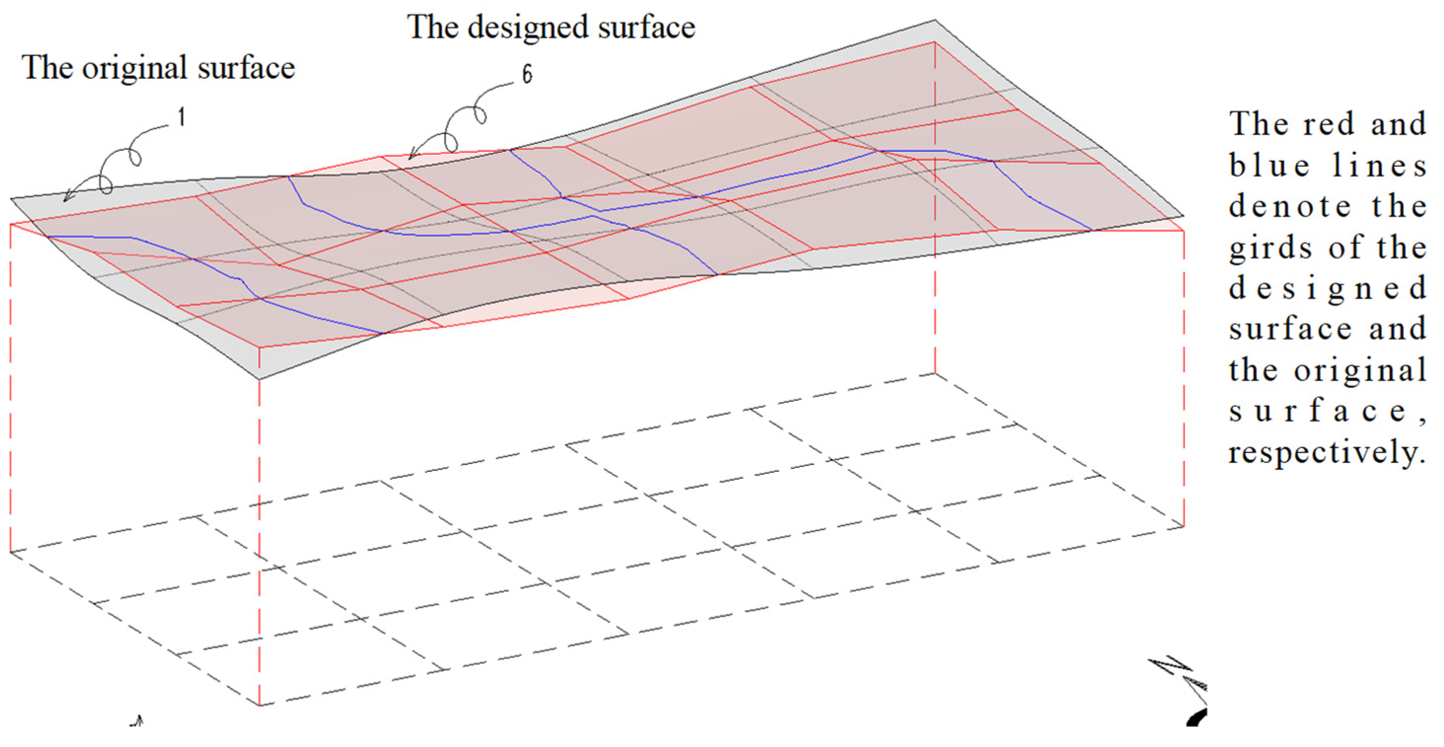
3.1. The Designed Surface

The main challenge in solving the basic model (Equation (7)) mentioned above is the form of the designed surface. This surface cannot be simplified as a flat surface, as it is not optimized for the cut-and-fill volume. Meanwhile, the surface should not be overly complicated, as it would make design and construction difficult. To achieve the desired designed surface, multiple options were considered and finally a hyperbolic paraboloid was adopted. Hyperbolic paraboloids are often used in architecture and engineering due to their structural stability and aesthetic appeal. This type of surface resembles a saddle and is characterized by a profile where the lines parallel to the four sides are all straight lines, as shown in Figure 3. In this respect, for each grid as illustrated in Figure 4, the  h m i  of grid i can be linearly described by the four node elevations of the corresponding block, namely  h i 1 h i 2 h i 3 , and  h i 4 , as follows:
h m i = A i h i 1 + B i h i 2 + C i h i 3 + D i h i 4
where  A i B i C i , and  D i  are the linear coefficients, and m is the number of grids. Further derivation gives
A i = ( y m i y i 2 ) ( x m i x i 4 ) ( y i 2 y i 1 ) ( x i 4 x i 1 )
B i = ( y m i y i 1 ) ( x m i x i 3 ) ( y i 2 y i 1 ) ( x i 3 x i 1 )
C i = ( y m i y i 2 ) ( x m i x i 1 ) ( y i 2 y i 1 ) ( x i 4 x i 1 )
D i = ( y m i y i 1 ) ( x m i x i 2 ) ( y i 2 y i 1 ) ( x i 3 x i 2 )

3.2. The Linear Transformation

To eliminate the absolute value in the objective function, a novel variable Vi is induced and the basic mathematical model (Equation (7)) is transformed into the following form:
Objective   function : min i = 1 m V i Constraint   condition : ( h m i z i ) s i V i ( h m i + z i ) s i V i h i h j k Δ L i j   Inequality   constraint   ( h m i z i ) s i = 0   Equality   constraint  
The objective function can be rewritten in matrix form as
min ( f T H )
where  f = 0 0 0 1 1 1 T H = h 1 h 2 h n V 1 V 2 V m T , and n is the number of blocks.
Substituting Equation (7) into the inequality constraints in Equation (12) gives
A i s i h i 1 + B i s i h i 2 + C i s i h i 3 + D i s i h i 4 V i z i s i A i s i h i 1 B i s i h i 2 C i s i h i 3 D i s i h i 4 V i z i s i h i h j k Δ L i j h i + h j k Δ L i j
We rewrite Equation (14) into matrix form as
A H K
where  A = 0 1 1 0 0 0 0 0 0 0 1 1 0 0 0 0 0 0 0 0 1 1 0 0 0 0 0 0 0 0 1 1 0 0 0 0 0 0 A 1 s 1 B 1 s 1 C 1 s 1 D 1 s 1 1 0 0 A 1 s 1 B 1 s 1 C 1 s 1 D 1 s 1 1 0 0 0 0 A m s m B m s m C m s m D m s m 0 0 1 0 A m s m B m s m C m s m D m s m 0 0 1   K = k Δ L 1 k Δ L 1 k Δ L i k Δ L n e k Δ L n e 2 ne z 1 s 1 z 1 s 1 z m s m z m s m 2 m T , and ne is the number of grid sides.
Similarly, substituting Equation (7) into the equality constraint in Equation (12) gives
A e q V = b e q
where  A e q = A e q 1 + A e q i + A e q n A e q i = A i s i B i s i C i s i D i s i n 0 0 m , and  b e q = i = 1 m z i s i .
Summarizing Equation (13), Equation (15), and Equation (16) obtains
min ( f T H ) , s . t . A H K A e q H = b e q
Equation (17) presents the linear programming model for the slope leveling of PV sites.  H  is a column vector of order (n + m) and is to be solved.  A  is a coefficient matrix of order (2 ne + 2 m) × (n + m).  f  and  H  are column vectors of order (n + m).  A e q  is a coefficient row vector of order (n + m).  K  is an inequality constraint vector and is a column vector of order (2 ne + 2 m).  b e q  is the coefficient constant of the equality constraint.

3.3. Calculation Steps

The calculation of the linear optimization model (Equation (17)) for PV slope leveling was implemented in MATLAB R2022a with vectorized matrix operations. Basic calculation steps (as shown in Figure 5) involve the following:
(1)
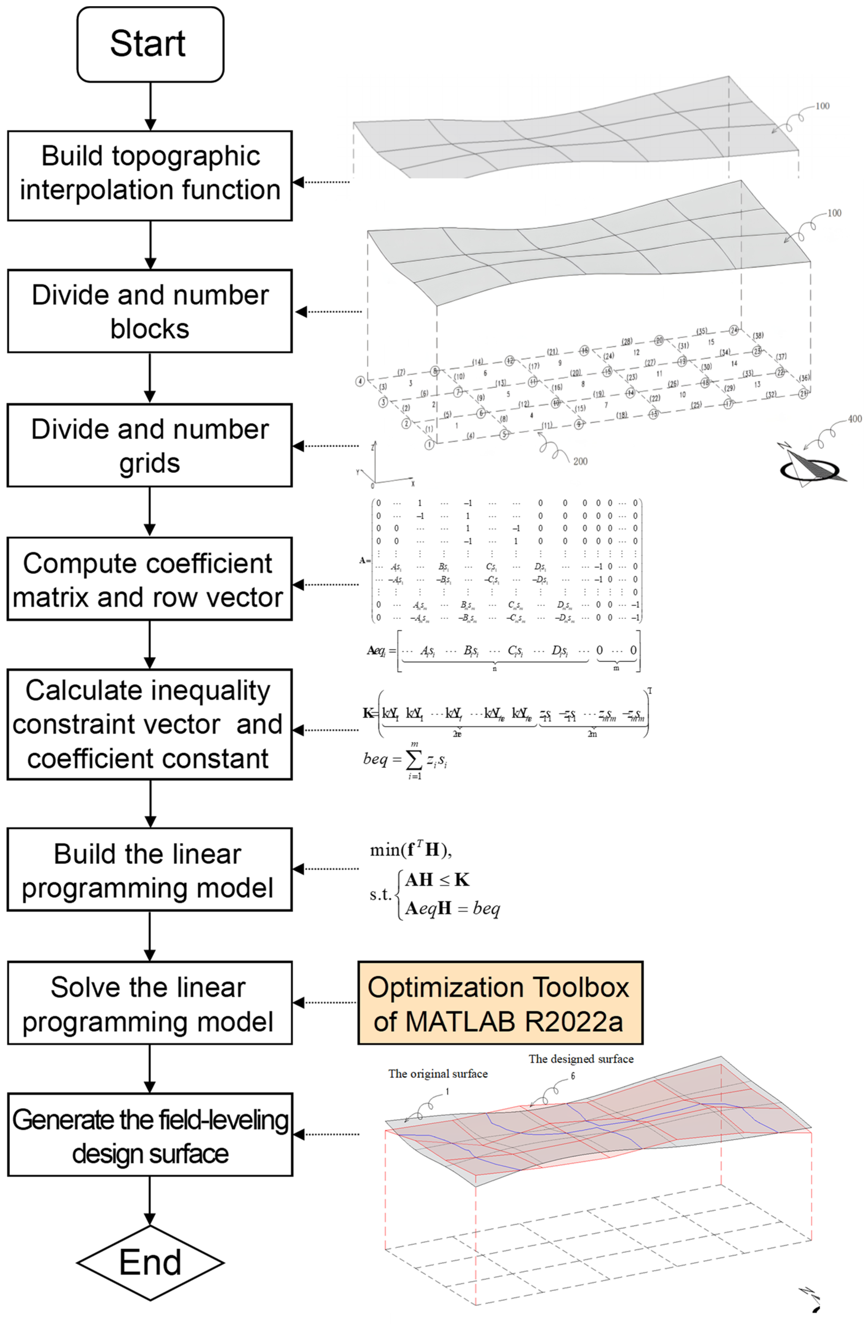
Building a topographic two-dimensional interpolation function. Based on the original topographic elevation point data, the topographic two-dimensional interpolation function is generated to calculate the ground elevations of the given plane coordinates.
(2)
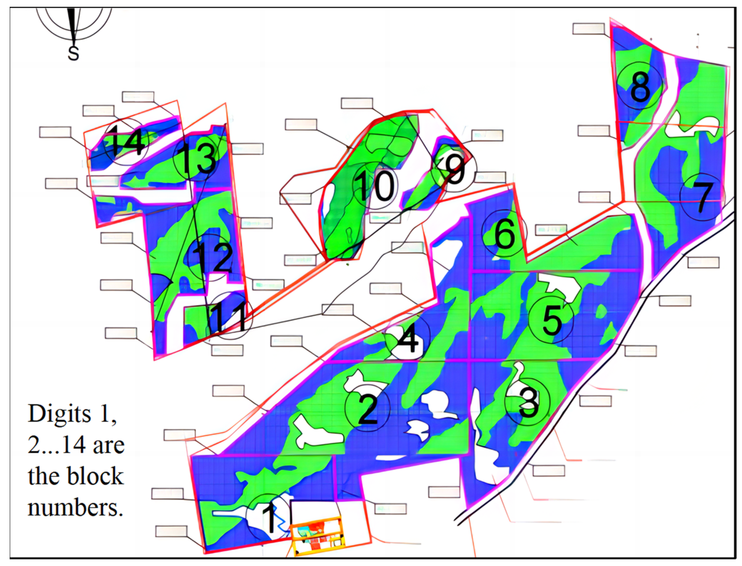
Dividing the PV site into blocks and numbering blocks.
(3)
Dividing blocks into grids and numbering grids.
(4)
Computing the coefficient matrix and row vector, namely  A  and  A e q .
(5)
Calculating the inequality constraint vector K and the coefficient constant  b e q .
(6)
Building the linear programming model as presented in Equation (18).
(7)
Solving the linear programming model. Using the optimization toolbox of MATLAB R2022a, the linear programming model in Equation (18) can be solved and optimum solution H can be obtained.
(8)
Generating the design surface of PV sites by connecting design elevations of each adjacent grid.

4. Results and Discussions

The proposed optimization methodology has been applied to implement slope leveling designs for numerous real PV sites. This section begins by comparing the results of the optimization methodology and the traditional segmented plane method, which is essentially a form of the least square method. Typical cases are used for this comparison. Afterwards, a parameter analysis of the proposed optimization method is presented, focusing on slope ratio, grid size, and block size. The detailed results are as follows.

4.1. Comparison of Our Linear Optimization Methodology and the Segmented Plane Method

The project is located in the eastern part of Luzon Island in the Philippines. It has a capacity of 283 MW and covers an area of 170 hectares. During the bidding and initial construction drawing phases (Figure 6), the site leveling design used the segmented plane method. The site was divided into 14 blocks, and each block was leveled separately. However, this traditional method resulted in a cut-and-fill volume of 840,000 m3. Despite undergoing five revisions, the corresponding leveling scheme was considered non-optimal and did not receive approval from the supervisory authority. Subsequently, our slope leveling methodology was employed for optimization calculations. The entire site was taken into account during the leveling calculation. The result yielded a cut-and-fill volume of only 350,000 m3, saving 58% of the project quantities and approximately USD 1.4 million in project costs compared to the original scheme. The construction drawings are displayed in Figure 7. Figure 7a depicts the leveling layout, and Figure 7b provides the leveling details of one section. In Figure 7a, the green areas represent the filling areas, while the red areas represent the excavation areas. These optimized construction drawings were approved by the supervisory authority on the first submission and were successfully implemented.
To provide a more detailed comparison between our optimization methodology and the segmented plane method, we conducted calculations using both methods for multiple real PV projects. The results are presented in Figure 8, clearly illustrating the substantial reduction in the cut-and-fill volume achieved by our optimization method compared to the segmented plane method for each project. The reduction ranges from 58% to 78%. Additionally, Figure 9 displays the variation in the optimized volume and optimized proportion with the project area. Generally, larger site areas correspond to greater optimization in project volume, with optimized ratios consistently exceeding 50%. Consequently, our linear optimization methodology demonstrates a significant effect in optimization compared to the traditional method. Moreover, larger site areas and more complex terrains tend to yield even more substantial optimization effects.
Moreover, the calculation speed of our linear optimization methodology also improves a lot compared with the segmented plane method. For a medium-volume project, the conventional method takes 4–7 days to obtain desirable design scheme, while our method just consumes 3–5 min to achieve the optimal scheme. Our linear optimization methodology is convenient in operation and fast in computation and mainly applies for ground-mounted centralized photovoltaic sites.

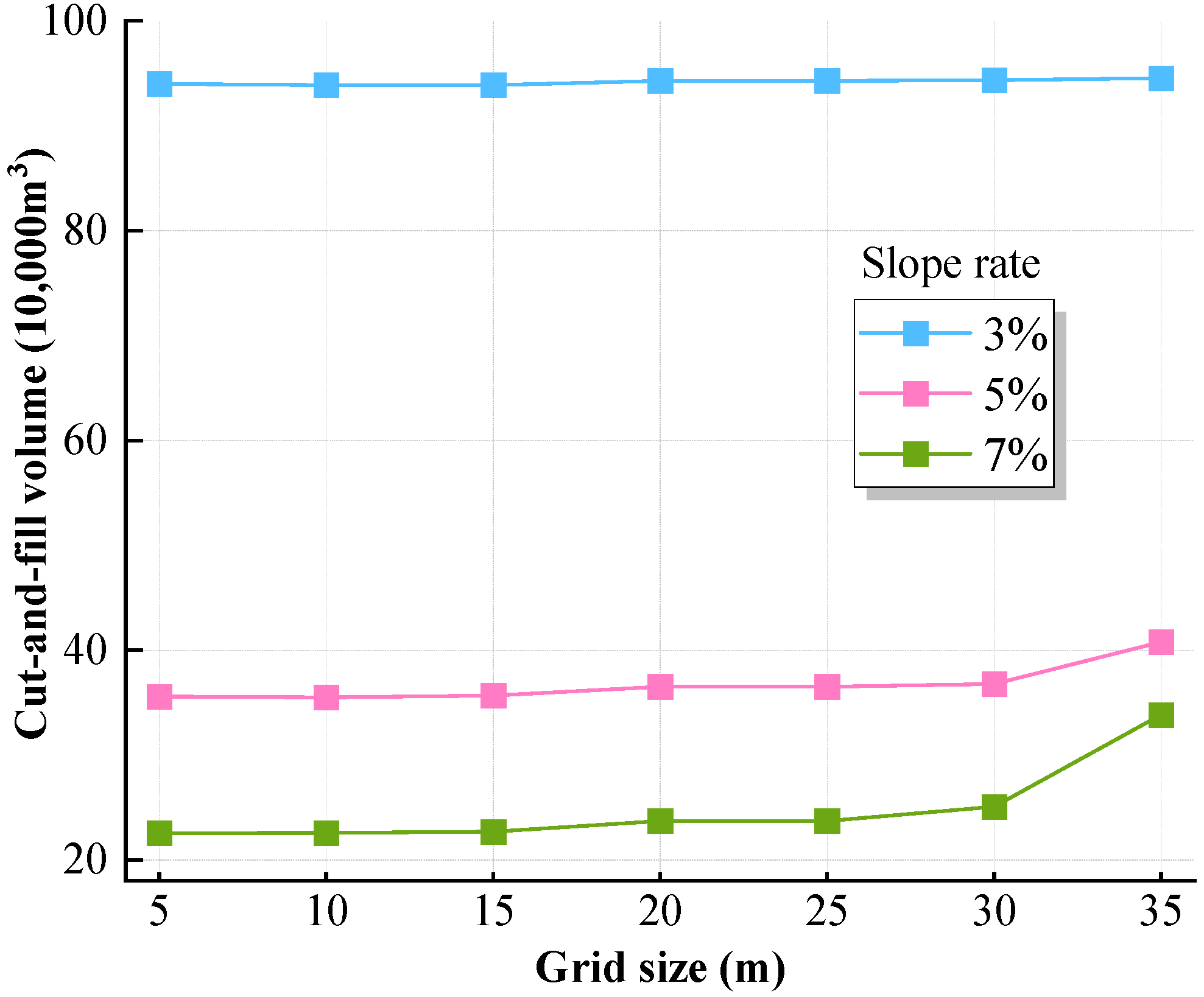
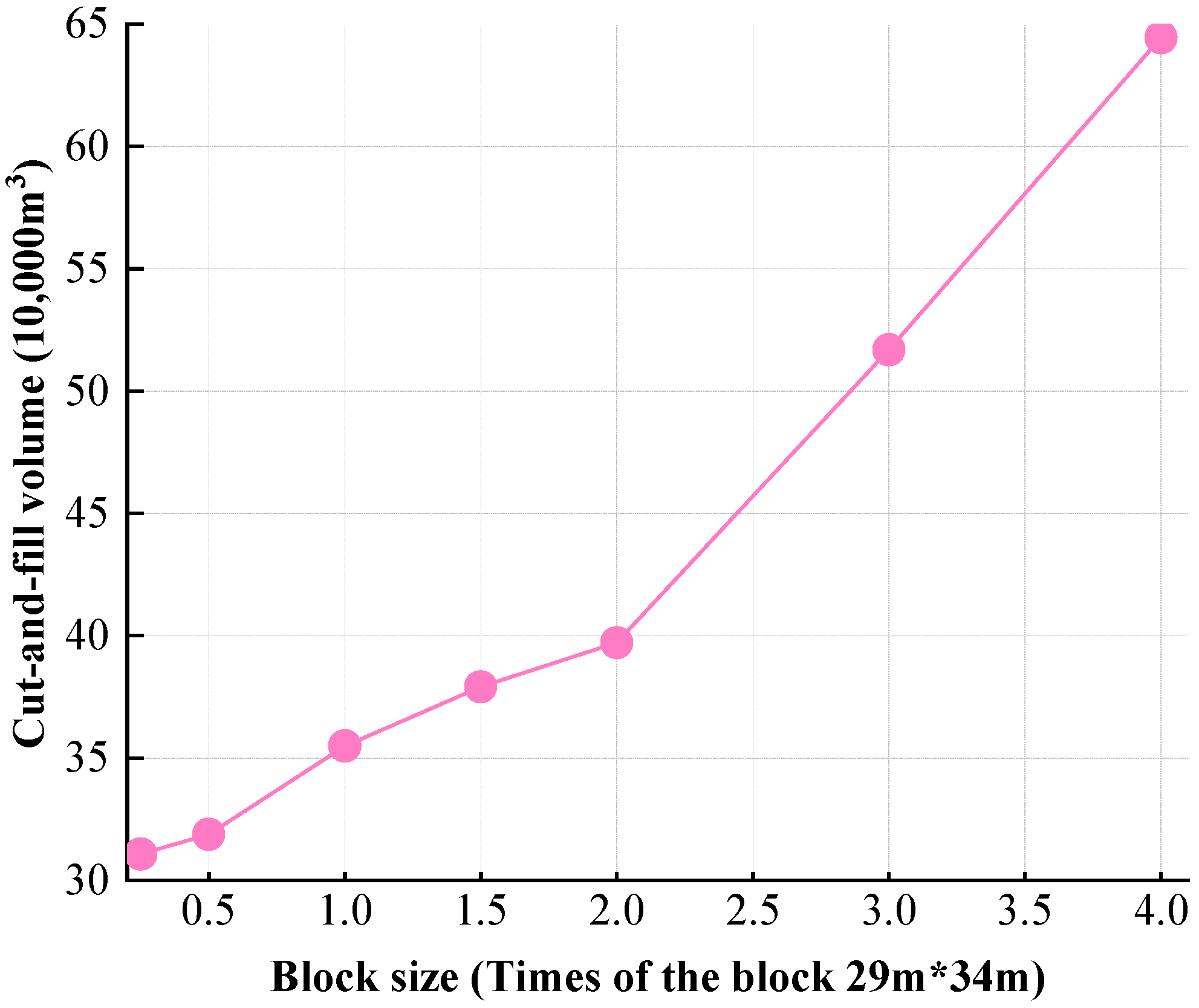
4.2. Parameter Analysis for the Linear Optimization Methodology

Slope ratio, grid size, and block size are important input parameters for using the linear optimization methodology to design a PV slope leveling. In order to understand how these factors affect the project volume, various parameters were set in the slope leveling calculation for the PV project mentioned above. The cut-and-fill volumes under different slope ratios, grid sizes, and block sizes were obtained and are shown in Figure 10, Figure 11, and Figure 12, respectively. Figure 10 demonstrates that the cut-and-fill volumes decrease as the slope ratios increase. When the slope ratios range from 0 to 3%, the decrease is significant, indicating a significant impact of the slope ratio on the project volume. When the slope ratios exceed 3%, the curve becomes more gradual, suggesting a lesser impact of the slope ratio on the project volume. Therefore, a slope ratio of 3% can be considered as the critical slope ratio. When the slope ratio is below the critical slope ratio, the cut-and-fill volume is greatly influenced by the designed slope ratio. On the other hand, when the designed slope ratio is higher than the critical slope ratio, the cut-and-fill volume is less affected by the designed slope ratio. For most PV slope leveling projects, a slope ratio of 3–7% is recommended. The most commonly used slope ratio is 5%.
In Figure 10, the four curves representing different grid sizes overlap, indicating that the cut-and-fill volume is not significantly affected by the grid size, which ranges from 5 to 30 m. To further explore the influence of the grid size, Figure 11 shows the changes in the cut-and-fill volume for additional grid sizes. It is observed that there is no substantial difference in the project volume among the three curves in Figure 11, except when the grid size changes from 30 m to 35 m for the curves with a slope ratio of 5% and 7%. This confirms that the impact of the grid size on the cut-and-fill volume is minimal. The grid size determines the accuracy of the calculation for the cut-and-fill volume. When designing the slope leveling of a PV field, the grid size is determined by the block size and it is recommended to be between 5 and 20 m. Smaller values can be used for sites with complex terrain. Additionally, Figure 11 also demonstrates a significant variation between slope ratios of 3% and 5%. This variation is attributed to the influence of the slope ratio on the cut-and-fill volume. It is observed that the impact of the slope ratio on the cut-and-fill volume decreases with higher slope ratios (greater than 3%). Therefore, Figure 11 presents a more pronounced variation between slope ratios of 3% and 5% compared to that between 5% and 7%.
Figure 12 illustrates the relationship between block size and the cut-and-fill volume using a grid size of 10 m and a slope of 0.05. As the block sizes increase, the cut-and-fill volumes also increase at a consistently high rate. This clearly demonstrates that block size has a significant impact on the overall volume. Using larger block sizes results in higher cut-and-fill volumes, which compromises the optimization of PV slope leveling. Conversely, smaller block sizes lead to complex and time-consuming calculations, as well as increased construction difficulty. Therefore, it is crucial to determine an appropriate block size when designing PV slope leveling. In general, a block size of 30–50 m is recommended. For sites with flat terrain, larger block sizes can be used, while sites with complex terrain are better suited for smaller block sizes.

5. Conclusions

PV slope leveling is characterized by its vast area, extremely undulating terrain, slope ratio constraint, and allowance for localized unevenness. However, there is currently a lack of an optimization design method specifically tailored for the slope leveling of ground-mounted centralized PV sites. To address this issue, we propose a linear optimization methodology that considers the unique characteristics of these projects. This method involves dividing the PV field into blocks and grids and using a hyperbolic paraboloid to simulate the surface for excavation. The optimization approach also takes into account cut-and-fill balance and slope ratio conditions, with the goal of minimizing the total cut-and-fill volume. With programming in MATLAB R2022a, the globally optimal solution for PV slope leveling was calculated. The basic programming steps include building a topographic two-dimensional interpolation function, dividing and numbering the blocks/grids, computing the matrices and vectors, integrating the linear optimization model, solving the linear model using the optimization toolbox, and finally generating and outputting the field-leveling design surface of the PV sites.
The effectiveness of the proposed linear optimization method was evaluated by calculating various real projects using both the proposed method and the segmented plane method. The results of the calculations clearly demonstrate that the optimization method can significantly reduce the cut-and-fill volume, ranging from 58% to 78% compared to the segmented plane method. This indicates a noteworthy improvement in the efficiency of optimizing the PV field layout when the proposed approach is utilized. Moreover, the advantages of the optimization method become even more pronounced as the site area increases and the topographical complexity becomes more intense, particularly in the design optimization of PV slope leveling. A parametric analysis involving slope ratio, grid size, and block size revealed that the grid size has a relatively minimal impact on the cut-and-fill volume, whereas the slope ratio and block size exert a significant influence. For typical PV projects, it is recommended to maintain a slope ratio between 3% and 7%, with grid sizes ranging from 5 to 20 m. Similarly, block sizes between 30 and 50 m are advised.
In summary, the proposed linear optimization methodology can provide an optimal slope leveling scheme for ground-mounted centralized PV projects. It is convenient to operate and fast to compute. Further investigation into the optimization of PV slope leveling should consider incorporating more site conditions, such as continuous rainfall and variable tilt angles of the racking systems.

Author Contributions

Methodology, data curation, writing—original draft preparation, Y.T. and N.Z.; software, J.Z. (Jianfeng Zhu) and Y.S.; validation, visualization, Y.C., W.Z. and J.Z. (Jianyong Zhao); resources, B.D., Y.W. and J.R.; funding acquisition, Y.T. and J.Z. (Jianfeng Zhu). All authors have read and agreed to the published version of the manuscript.

Funding

This research was funded by National Natural Science Foundation of China, grant number 52378378, and the Natural Science Foundation of Zhejiang Province, grant number LTGS23E080002 and LGG22E090002.

Data Availability Statement

Data will be provided on request.

Conflicts of Interest

The authors declare no conflicts of interest.

Nomenclature

V i Cut-and-fill volume of grid  i
s i Area of grid  i  
h m i 
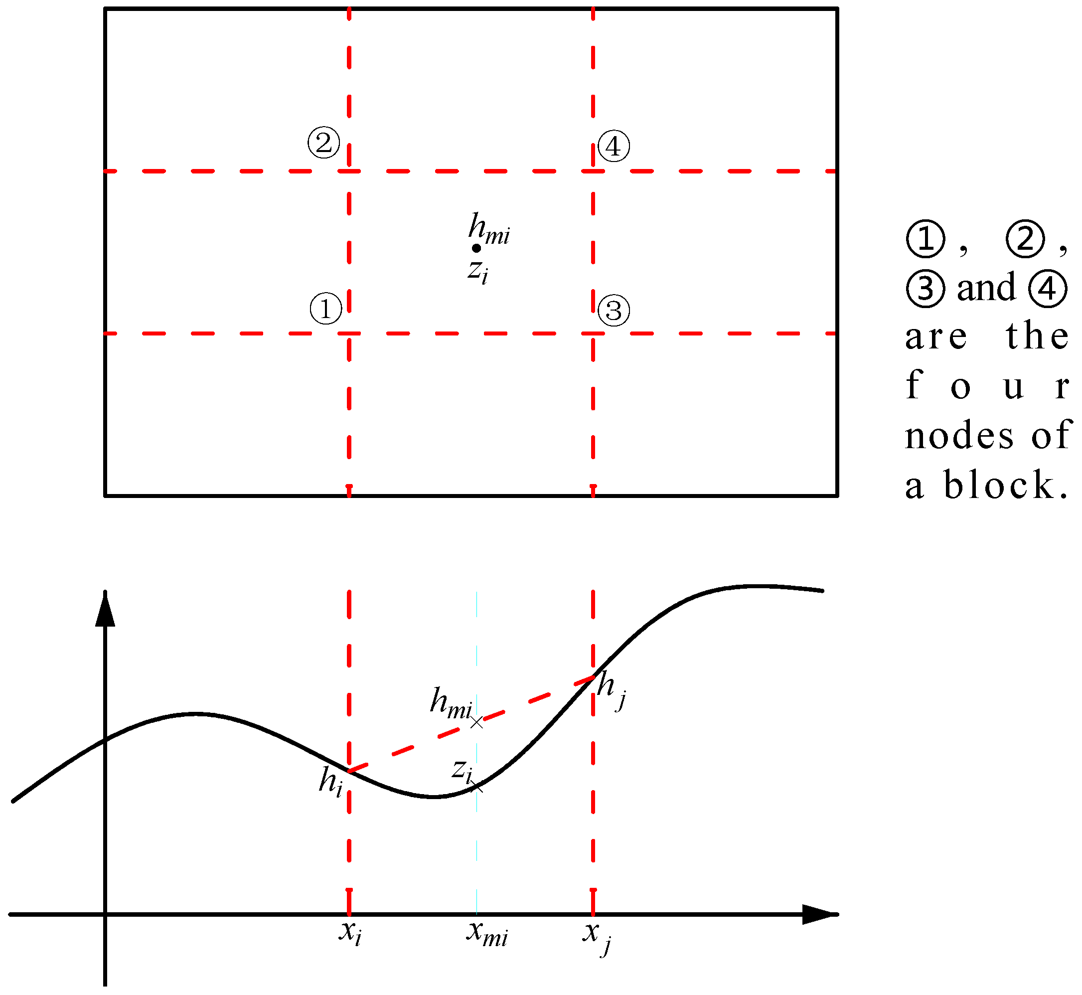
Elevation of the midpoint of grid i in the fitted surface
z i Elevation of the midpoint of grid i in the original surface
k Slope ratio limit
Δ L i j Distance of two adjacent grid nodes  i  and  j  
h i 1 h i 2 h i 3 h i 4 Elevations of the four nodes of block  i  
A i B i C i D i Fitting coefficients
A e q i Fitting coefficient row vector of block  i  
A Inequality constraint coefficient matrix
K Inequality constraint constant vector
H Global column vector of elevation
f Global column vector of the fitting coefficient
A e q Equality constraint coefficient vector
b e q Equality constraint constant

References

  1. Thapar, V. A revisit to solar radiation estimations using sunshine duration: Analysis of the impact of these estimations on energy yield of a PV generating system. Energy Sources Part A 2019, 45, 1–25. [Google Scholar] [CrossRef]
  2. Wang, J.; Xu, Y.J.; Wu, C.J.; Yang, B.H. The status and development of solar photovoltaic industry under the background of carbon neutrality. Energy Storage Sci. Technol. 2022, 11, 731–732. [Google Scholar]
  3. Lu, H.; Zhao, W. CFD prediction of dust pollution and impact on an isolated groundmounted solar photovoltaic system. Renew. Energy 2019, 131, 829–840. [Google Scholar] [CrossRef]
  4. Kulsoom, F.; Ahmad, F.M.; Hasmat, M.; Fausto, P.G.M. Experimental analysis of dust composition impact on Photovoltaic panel Performance: A case study. Sol. Energy 2024, 267, 112206. [Google Scholar] [CrossRef]
  5. Bouraiou, M.; Hamouda, A.; Chaker, M.; Mostefaoui, S.; Lachtar, M.; Sadok, N.; Boutasseta, M.; Othmani, A.I. Analysis and evaluation of the impact of climatic conditions on the photovoltaic modules performance in the desert environment. Energy Conver. Manag. 2015, 106, 1345–1355. [Google Scholar] [CrossRef]
  6. Yang, Y.; Wang, Z.; Li, B.; Guan, J. The impact of photovoltaic projects on ecological corridors through the Least-Cost Path model. Glob. Ecol. Conserv. 2023, 42, e02381. [Google Scholar] [CrossRef]
  7. Song, C.C.; Guo, Z.L.; Liu, A.G.; Zhang, H.Y.; Liu, R.; Zhang, H.R. Application of photovoltaics on different types of land in China: Opportunities, status and challenges. Renew. Sustain. Energy Rev. 2024, 191, 114146. [Google Scholar] [CrossRef]
  8. Selimefendigil, F.; Oztop, H.F. Efficient cooling system design by using different shaped nanoparticles and rotating cylinders in channel system for photovoltaic thermal management. Numer. Heat Transf. Part B Fundam. 2024, 1–24. [Google Scholar] [CrossRef]
  9. Abbassi, R.; Saidi, S.; Urooj, S.; Alhasnawi, B.N.; Alawad, M.A.; Premkumar, M. An accurate metaheuristic mountain gazelle optimizer for parameter estimation of single- and double-diode photovoltaic cell models. Mathematics 2023, 11, 4565. [Google Scholar] [CrossRef]
  10. Barbón, A.; Bayón-Cueli, C.; Bayón, L.; Carreira-Fontao, V. A methodology for an optimal design of ground-mounted photovoltaic power plants. Appl. Energy 2022, 314, 118881. [Google Scholar] [CrossRef]
  11. Sulaiman, S.I.; Rahman, T.K.A.; Musirin, I.; Shaari, S.; Sopian, K. An intelligent method for sizing optimization in grid-connected photovoltaic system. Sol. Energy 2012, 86, 2067–2082. [Google Scholar] [CrossRef]
  12. Saidi, S.; Abbassi, R.; Hassen, W.B.; Chebbi, S. Solar photovoltaic energy system-based shunt active filter for electrical energy quality improvement. Int. J. Simul. Process Model. 2016, 11, 119–126. [Google Scholar] [CrossRef]
  13. Charabi, Y.; Rhouma, M.B.H.; Gastli, A. Siting of PV power plants on inclined terrains. Int. J. Sust. Energy 2014, 35, 834–843. [Google Scholar] [CrossRef]
  14. Fast Software. Available online: https://www.fast.com.cn/ (accessed on 1 June 2024).
  15. Autodest Official. Available online: https://www.autodesk.com/asean/products/civil-3d/ (accessed on 1 June 2024).
  16. Jat, M.L.; Gathala, M.K.; Ladha, J.K.; Saharawat, Y.S.; Jat, A.S.; Kumar, V.; Sharma, S.K.; Kumar, V.; Gupta, R. Evaluation of precision land leveling and double zero-till systems in the rice–wheat rotation: Water use, productivity, profitability and soil physical properties. Soil Tillage Res. 2009, 105, 112–121. [Google Scholar] [CrossRef]
  17. Song, X.Y.; Yang, Y.R.; Li, Y.R. Optimization of site-leveling design of thermal power projects for trough solar energy in large desert area. Electr. Power Surv. Des. 2021, 7, 50–57. [Google Scholar] [CrossRef]
  18. Song, X.M. Comparison and selection of vertical layout plan for solar photovoltaic site. Electr. Power Surv. Des. 2021, 8, 63–67. [Google Scholar] [CrossRef]
  19. You, H.P.; Zhang, M.; Wang, T.T. Application of mathematical morphology in the terrain treatment of photovoltaic power stations. Acta Energ. Sol. Sin. 2015, 36, 2341–2346. [Google Scholar]
  20. Yang, X.D.; Sun, J. General layout and vertical design optimization of solar photovoltaic power station—20 MWp project of Jinshan Photovoltaic Power Field Phase I, Guyang County, Baotou, Datang. Sol. Energy 2012, 13, 37–41. [Google Scholar] [CrossRef]
  21. Fan, N. The calculation method of site leveling for solar power station in the desert area. Low Temp. Archit. Technol. 2020, 42, 147–149. [Google Scholar] [CrossRef]
  22. Hamid, R.V.; Mohammad, S.; Ali, S.T.; Mohammad, A.A.; Saeid, E.; Mahboubeh, A.K.; Maryam, M.B.; Kaveh, O.A. A Simple Method for Land Grading Computations and its Comparison with Genetic Algorithm (GA) Method. Int. J. Res. Stud. Agric. Sci. 2017, 3, 26–38. [Google Scholar] [CrossRef]
  23. Ebne, J.R. Weighted average method for land grading design. J. Irrig. Drain. Eng. 2004, 130, 239–247. [Google Scholar] [CrossRef]
  24. Hossein, S.S.; Faride, B.; Mahamad, M. Optimizing land leveling by applying warped surface. Int. J. Eng. Prod. Res. 2015, 26, 39–44. [Google Scholar] [CrossRef]
  25. Safa, N.H.; Ahmed, M.A. Land grading design by using nonlinear programming. J. Irrig. Drain. Eng. 1990, 116, 219–226. [Google Scholar] [CrossRef]
  26. Warren, H.; Yves, L.; Faisal, R. A mixed-integer linear programming model to optimize the vertical alignment considering blocks and side-slopes in road construction. Eur. J. Oper. Res. 2015, 241, 631–641. [Google Scholar] [CrossRef]
  27. Lin, C.Y.; Hazela, P. Genetic algorithms in structural optimization problems with discrete and integer design variables. Eng. Optim. 1992, 19, 309–327. [Google Scholar] [CrossRef]
  28. Huang, J.; Yuan, Y.; Cui, W.; Zhan, Y. An approach based on Decision Tree to agricultural land grading. In Proceedings of the 2010 International Conference On Computer Design and Applications, Qinhuangdao, China, 25–27 June 2010; pp. 246–249. [Google Scholar] [CrossRef]
  29. Xia, Y.; Liu, Y.; Hong, X.; Liu, D. Application of binary tree based SVMs approach to land grade evaluation. Proc. SPIE Int. Soc. Opt. Eng. 2009, 7492, 1–7. [Google Scholar] [CrossRef]
  30. Reddy, S.L. Optimal land grading based on genetic algorithms. J. Irrig. Drain. Eng. ASCE 1996, 122, 183–188. [Google Scholar] [CrossRef]
Figure 1. Schematic image of the fitting process.
Buildings 14 01858 g001
Figure 2. Schematic diagram of the block and grids.
Buildings 14 01858 g002
Figure 3. Schematic diagram of the designed surface.
Buildings 14 01858 g003
Figure 4. Schematic diagram of the grid division.
Buildings 14 01858 g004
Figure 5. Flow diagram of the proposed linear optimization methodology.
Buildings 14 01858 g005
Figure 6. Construction drawings by the segmented plane method (using FlyTime software).
Buildings 14 01858 g006
Figure 7. Construction drawings by our linear optimization methodology. (a) Site leveling layout; (b) site leveling details of one section.
Buildings 14 01858 g007
Figure 8. Calculation results by the segmented plane method and our linear optimization method.
Buildings 14 01858 g008
Figure 9. Change in the optimized cut-and-fill volume/proportion with the project area.
Buildings 14 01858 g009
Figure 10. Change in the cut-and-fill volume with the design slope ratio.
Buildings 14 01858 g010
Figure 11. Change in the cut-and-fill volume with the grid size.
Buildings 14 01858 g011
Figure 12. Variation in the cut-and-fill volume with the block size.
Buildings 14 01858 g012
Disclaimer/Publisher’s Note: The statements, opinions and data contained in all publications are solely those of the individual author(s) and contributor(s) and not of MDPI and/or the editor(s). MDPI and/or the editor(s) disclaim responsibility for any injury to people or property resulting from any ideas, methods, instructions or products referred to in the content.

