Article

Experimental and Numerical Investigation of a New Type of Composite Slab with a Separate Joint

1
Key Laboratory of Concrete and Prestressed Concrete Structures of the Ministry of Education, Southeast University, Nanjing 211189, China
2
School of Civil Engineering, Southeast University, Nanjing 211189, China
3
Nanjing Dong-Da Modern Prestressed Engineering Co., Ltd., Nanjing 210018, China
*
Author to whom correspondence should be addressed.
Buildings 2024, 14(7), 1890; https://doi.org/10.3390/buildings14071890
Submission received: 18 April 2024 / Revised: 9 June 2024 / Accepted: 11 June 2024 / Published: 21 June 2024
(This article belongs to the Special Issue Editorial Board Members’ Collection Series: Building Structures Ⅱ)

Abstract

:
This study proposes a new type of composite slab with a separate joint, which not only improves the assembly rate but also enables unsupported construction. A static loading test was conducted to investigate the bending behavior of the composite slab with a separate joint under a distributed load. The test results showed that the test composite slab had good integrity and crack resistance. The separate joint can effectively transmit internal forces and conform to the requirements of practical engineering. In addition, a finite element model was developed for the composite slab. The experimental load and numerical load corresponding to the longitudinal crack penetrating the bottom surface of the slab were 9.0 kN/m2 and 8.6 kN/m2, respectively, with an error of less than 5%. It was demonstrated that the finite element model can accurately predict the mechanical behavior of the composite slab.

1. Introduction

Prefabricated structures, whose components are manufactured in factories and assembled on-site, can significantly shorten construction time and promote the standardization of building production [1,2]. Currently, the most commonly used concrete slab for prefabricated structures in China is the composite slab with lattice girders, which is composed of a cast-in situ topping and a precast plank with lattice girders. The existence of lattice girders can enhance the stiffness of the precast plank and increase the bonding performance between the precast plank and the cast-in situ topping. However, the slab thickness adopted in China is smaller, mostly 120 mm, compared to the 180 mm thick slabs used in Germany. The smaller thickness limits the improvement in the stiffness provided by the lattice girder for the precast plank [3]. Consequently, a large number of vertical supports are often required during construction, increasing the construction period and production costs. To address the aforementioned issue, the authors [4] proposed a new type of composite slab. The precast plank of this composite slab is shown in Figure 1. The cast-in situ concrete topping is only poured into the notches around the perimeter of the precast plank. This composite slab not only allows for construction without vertical supports but also reduces the on-site wet workload, offering broad application prospects.
In engineering applications of composite slabs, multiple precast planks are typically connected through joints to increase the span of the composite slab. The joints of composite slabs are the weakest areas and are prone to cracking under complex stress conditions. The bearing capacity of the composite slabs is greatly influenced by the mechanical performance of the joint [5]. Currently, the common types of joints used for composite slabs in China mainly include traditional, integral, and separate types, as illustrated in Figure 2. The traditional joints have poor crack resistance, due to the discontinuous stress transmission of the steel bars, as shown in Figure 2a. Although integral joints can continuously and effectively transmit the stress of the reinforcements, the requirement for additional formwork during the casting of the concrete topping reduces production efficiency, as shown in Figure 2b. The separate joints are equipped with additional steel bars to ensure the effective transmission of shear force and bending moment. On the other hand, the precast planks can serve as permanent formwork for pouring concrete topping, as depicted in Figure 2c. Due to its faster construction speed and more convenient procedures compared to traditional and integral joints, the separate joints have attracted the attention of many experts and scholars. Wu et al. [6] introduced a novel composite slab with separate joints and conducted full-scale bending tests to evaluate the flexural behavior of the joint. They discovered that the longitudinal short reinforcement placed at the joints can increase the cracking load of the slab and has little effect on the flexural stiffness after cracking. Ye et al. [7,8] experimentally investigated the flexural behaviors of the separate joint between composite slabs with lattice girders. The results indicated that the flexural performance of composite slabs with a separate joint was essentially consistent with that of cast-in situ concrete slabs. Wang et al. [9], Liu et al. [10], and Yu et al. [11] investigated the bending performance of latticed girder composite slabs connected with separate joints. Their studies demonstrated that an appropriate spacing of lattice girders can make the stress distribution in the cross-section more uniform, thereby improving the bearing capacity of the slab. Xiao et al. [12] studied the flexural behavior of composite slabs with a groove splicing joint. Their finding was that the groove splicing joint is slighter lower than that of cast-in situ slabs. Kim and Shim [13] carried out bending tests on the half-depth precast slab with a loop joint and demonstrated that this joint has good crack resistance and bearing capacity. Zhang et al. [14,15] provided an experimental work on the flexural behavior of latticed girder composite slabs with a separate joint and revealed that the bearing capacity of the composite slab can meet the requirements of design code. Additionally, the method of densifying the lattice girder at the joint can effectively restrict the development of cracks. Stehle et al. [16] experimentally investigated the flexural behavior of composite slabs with separate joints. The test results showed that separate joints can be reliably applied to the two-way composite slabs. Altoubt et al. [17] found that the addition of steel bars can effectively enhance the shear bearing capacity of composite slabs with separate joints.
From the above studies, it can be seen that recent research has mainly focused on the separate joints of the composite slab with lattice girders. For the new type of composite slab [4], it is still unclear whether the detailed configurations of the separate joint can meet the requirements of its engineering practice. Considering that the area of the interface between the precast plank and the cast-in situ topping is significantly reduced in this composite slab compared to traditional composite slabs, it may affect the bonding performance of the interface. Therefore, it is necessary to conduct a bending test on the new type of composite slab with a separate joint.
In this study, a new type of composite slab with a separate joint was designed to be tested under a distributed load. The mechanical behavior of the new composite slab with a separate joint was investigated. A detailed finite element model (FEM) was developed, and its accuracy was validated against experimental results. The model can be used to further study the mechanical performance of the composite slab with a separate joint.

2. Experimental Investigation

2.1. Specimen and Material Property

This study designed a new type of composite slab with a separate joint according to the technical specification for precast concrete structures (JGJ1-2014) [18]. The length, width, and thickness of the composite slab were 6380 mm, 3340 mm, and 120 mm, respectively. The slab consisted of two precast planks and a cast-in situ concrete topping, as shown in Figure 3. All steel bars used in the composite slab had the same diameter of 8 mm. The steel bar arrangement in the precast plank is depicted in Figure 4. In addition, to prevent the concrete at the supports from being crushed during loading, steel plates with dimensions of 500 mm × 150 mm × 15 mm were embedded at the bottom surface of the precast plank. The detailed configuration of the separate joint between the two precast planks is illustrated in Figure 5. It should be noted that the gap between the bottoms of the two precast planks was filled with various materials, as shown in Figure 5. The thickness of the concrete cover in the composite slab was 15 mm.
The production process of the slab consisted of two stages. The first stage was the fabrication of precast planks. The reinforcement cages were placed into the formwork, as shown in Figure 6a. Concrete was then poured into the formwork to produce the precast plank, as depicted in Figure 6b, followed by a 28-day curing period. The second stage was casting the concrete topping. The cured precast planks were assembled together, and additional steel bars were tied, as shown in Figure 6c. Concrete was poured into the grooves on the top surface of the precast planks. Prior to pouring, the gap between the bottom of the precast planks needed to be filled with materials. Firstly, a PE rod was inserted into the gap, and the gap was filled with anti-crack mortar, as shown in Figure 6d,e. Next, a layer of anti-crack mortar was applied to the bottom surface of the slab, and alkali-resistant mesh fabric was placed, as depicted in Figure 6f,g. Finally, the bottom surface of the slab was leveled using the crack-resistant mortar, as shown in Figure 6h.
During the concrete pouring process, a total of six concrete cubes with dimensions of 150 mm × 150 mm × 150 mm were set aside for measuring the compressive strength of concrete on the day of testing [19]. The measured compressive strengths of the precast plank and the cast-in situ concrete topping are shown in Table 1. The material properties of the steel bars adopted in the composite slab were obtained through uniaxial tensile tests [20]. The test results are shown in Table 2.

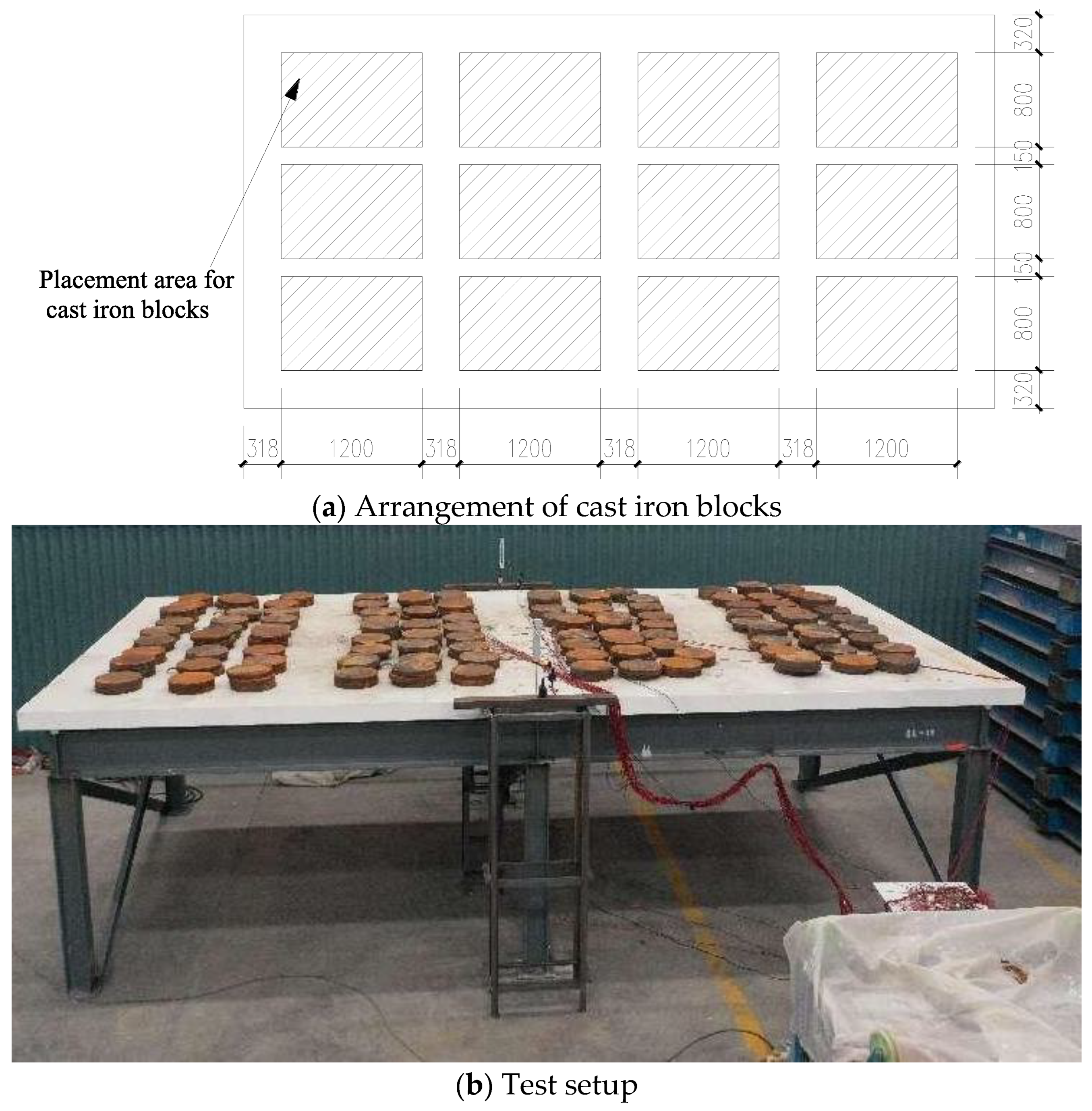
2.2. Testing Setup, Instrument, and Loading Protocol

Figure 7 shows the loading device, which consisted of a steel frame and four rollers placed on the beam of the steel frame. The slab was directly placed on the rollers to form a four-sided simple support. The total height of the steel frame was 1.8 m, and the space beneath the slab was primarily used for the following tasks: (1) installing dial gauges and displacement gauges; (2) reading dial gauges during the test; and (3) marking crack positions and the corresponding load. The distributed load was applied to the top surface of the slab through cast iron blocks. Before starting the test, the leveling of the steel frame must be carried out. To avoid the arching effect caused by the excessive height of cast iron blocks during loading, there should be some gaps between the piled cast iron blocks. Moreover, cast iron blocks should not be placed near the supports. The layout of the loading area is shown in Figure 7a. In order to verify whether the test equipment can work properly, a preloading process was carried out. The preloading was divided into three loading stages, with load values of 0.5 kN/m2, 1.0 kN/m2, and 1.5 kN/m2, respectively. During the preloading process, the midspan deflection of the specimen increased linearly with the applied load. Following the preloading, the formal loading commenced. The load was divided into 15 stages, gradually increasing until it reached 13.95 kN/m2. The load increment per stage is specified in Table 3. After completing each stage of loading, the load was maintained for 24 h, and the crack-development characteristics at the bottom surface of the slab were depicted using a marker pen. The loading process continued until the specimen failed or the total height of the cast iron block was too high to achieve manual loading.
In order to measure the deflection of the slab under each stage of loading, a linear variable displacement transducer was placed at the midspan of the bottom surface of the slab. Additionally, a dial gauge was positioned beside the linear variable displacement transducers for further verification, ensuring the accuracy of the data.

3. Test Results

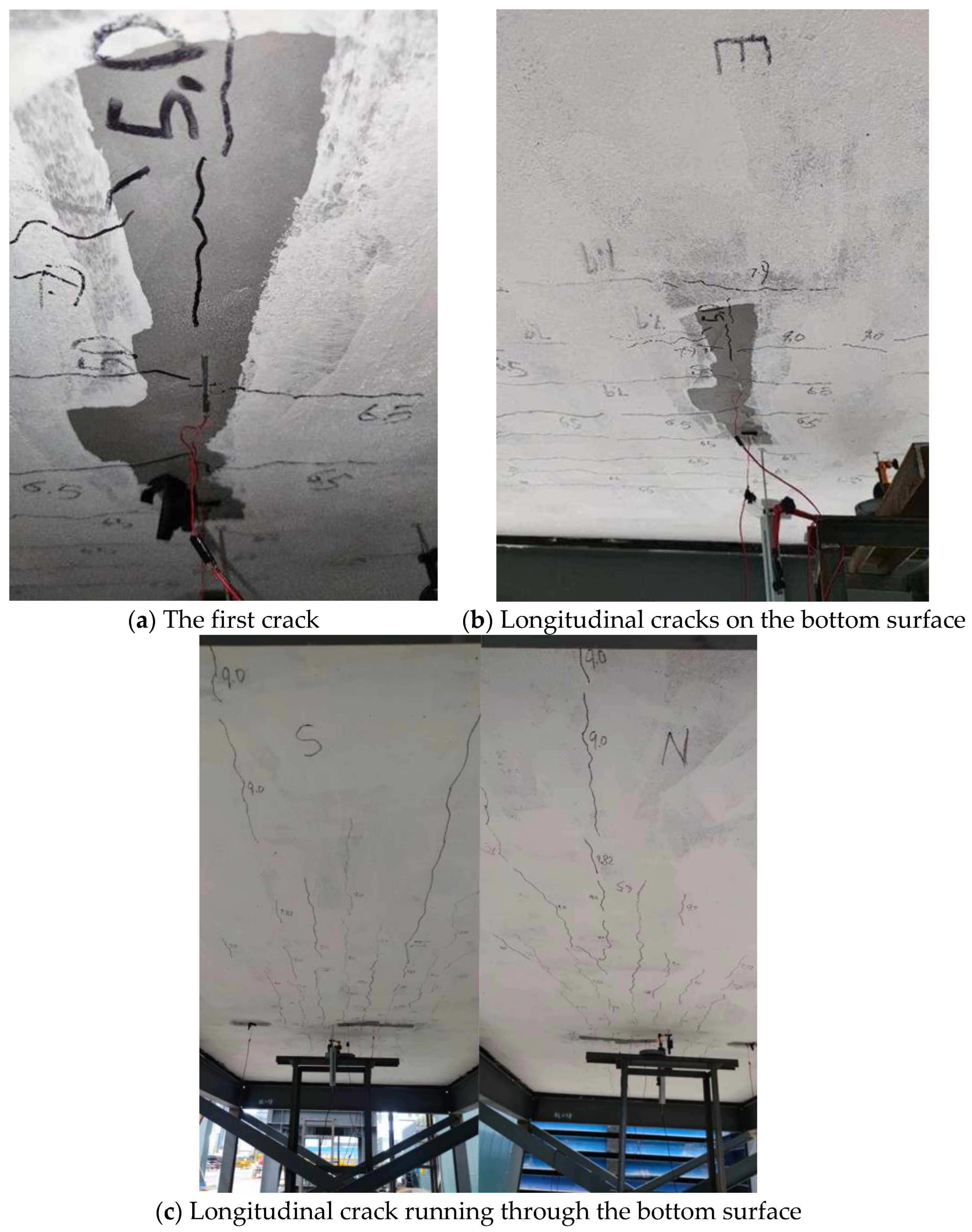
3.1. Crack Pattern Observations

Figure 8 depicts the crack patterns of the slab at different loading stages. When the load reached 5.0 kN/m2, the initial crack appeared at the midspan of the bottom surface and extended along the short edge direction of the slab, as depicted in Figure 8a. After being loaded to 6.5 kN/m2, several short longitudinal cracks were observed at the bottom surface, as depicted in Figure 8b. With the increase of the load, the number of cracks at the bottom surface of the slab increased. When the load reached 9.0 kN/m2, longitudinal cracks ran through the bottom surface, as shown in Figure 8c. As the load increased to 11.97 kN/m2, diagonal cracks appeared on the bottom surface. Finally, when the specimen was loaded to 13.95 kN/m2, the maximum crack width at the bottom surface was 0.8 mm, which was less than the crack width corresponding to the bearing capacity (1.5 mm) [21]. During the entire loading process, no significant relative slip occurred at the interface. The initial crack width was less than 0.3 mm after the loading was completed.

3.2. Load—Deformation Behavior

Figure 9 illustrates the relationship between the midspan deflection and the total distributed load applied on the top surface. The load values did not include the gravity load of the specimen. The displacements did not take into account the deflection caused by the self-weight of the specimen when it was placed on the steel frame before loading. As shown in Figure 9, it can be observed that the midspan deflection and the load exhibited a nearly linear relationship in the initial loading stage of the test. After the fifth stage of loading, there was a slight decrease in the slope of the curve, corresponding to the occurrence of cracks in the bottom surface. Upon reaching the eighth stage of loading, longitudinal cracks penetrated the bottom surface, further weakening the flexural stiffness of the floor slab. After loading was completed, the midspan deflection of the slab reached 21.73 mm (1/284 of the span of the slab), which is much lower than the failure deflection (1/50 of the span of the slab) [21].

3.3. Evaluation of Flexural Performance

For building structures, the code for the design of building structures (GB5009-2012) [22] divides the combination of load effects into fundamental combinations, accidental combinations, characteristic combinations, frequent combinations, and quasi-permanent combinations. In the design of building structures, load effect combinations should be formulated based on the possible concurrent loads that the structure may experience during its service life, considering both the bearing capacity and serviceability limit state. As indicated in Section 3.2, the test slab was not loaded to its failure. Therefore, this subsection evaluates whether the design of this new slab can meet the serviceability limit state requirements. For the structures subjected to long-term loading, the evaluation method is to verify whether the deformation or crack width of the components under the quasi-permanent combination of loads satisfies the specified limits [22]. The quasi-permanent coefficient for floor loads is related to the architecture categories. For residential, commercial, and storage rooms, the quasi-permanent combination values of floor loads are 2.3 kN/m2, 3.25 kN/m2, and 5.5 kN/m2 respectively [22]. For slabs with a span of less than 7 m, the slab reaches the serviceability limit state when the deflection reaches 1/200 of the span (30.9 mm), or the crack width reaches 0.3 mm, according to the code for the design of concrete structures (GB50010-2010) [23]. Table 4 summarizes the midspan deflection and cracking of the test slab used in residential, commercial, and bookstore buildings under the corresponding quasi-permanent load combinations. In Table 4, Fp represents the load quasi-permanent combination value, and Δ represents the midspan deflection of the slab under the corresponding quasi-permanent combination value. From Table 4, it can be seen that whether the slab is applied in residential, commercial, or storage rooms, their deflection and crack width are both below the limit value of the serviceability limit state, indicating that the composite slab has good prospects for engineering applications.

4. Finite Element Analysis
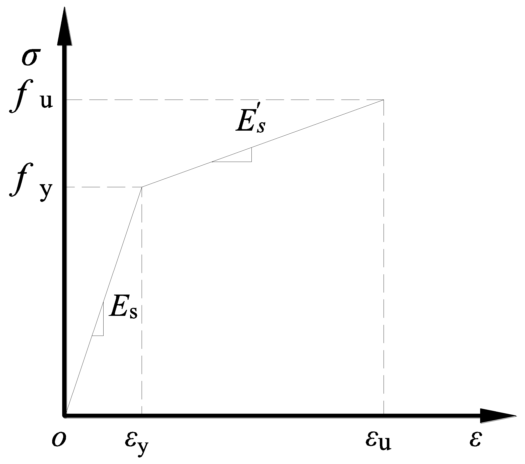
This section develops a finite element modeling method based on the software ABAQUS 2016 for the new type of composite slab with a separate joint proposed in this study. The accuracy of the finite element (FE) model was validated by comparing its analysis results with experimental results.

4.1. Material Model

In ABAQUS, three commonly utilized models were employed to describe the material properties of concrete: the concrete damaged plasticity model, the concrete smeared cracking model, and the cracking model for concrete. The concrete cracking model is exclusively applicable to the ABAQUS/Explicit module, while the concrete smeared cracking model overlooks the discrepancies in material properties between tension and compression. The concrete damaged plasticity model, being a continuous medium plasticity-based damage model, exhibits excellent convergence. It adequately captures material performance discrepancies under tension and compression through the introduction of damage factors. Hence, the concrete damaged plasticity model was chosen to characterize the mechanical behavior of the concrete in tension and compression, which requires inputs of multiaxial plasticity parameters, the stress–strain behavior of concrete, and the damage factor to complete its definition. The plasticity parameters, including a dilation angle of 40°, an eccentricity of 0.1, a concrete biaxial-to-uniaxial cylinder compressive ratio of 1.16, and a ratio of tensile to compressive meridian of 0.667, were adopted [24]. Regarding the stress–strain behavior of concrete, it was established in accordance with GB50010-2010 [23]. The damage factors under tension and compression were determined using the energy equivalence method proposed by Sidoroff [25]. In this model, the density of concrete was assumed to be 2400 kg/m3. The elastic behavior of concrete was simulated by defining the elastic modulus and Poisson’s ratio. Poisson’s ratio for concrete was taken as 0.2, and the modulus of elasticity (Ec) was calculated using Equation (1), provided in GB/T 50152-2012 [21].
E c = 10 5 2.2 + 34.7 f cu   N / mm 2
In Equation (1), fcu is the measured value of the compressive strength of concrete cubes, as shown in Table 1.
Bilinear strain hardening models were employed to depict the stress–strain relationship of the steel bars, delineated into elastic and hardening stages, as shown in Figure 10. The elastic modulus (Es), yield strength (fy), and ultimate tensile strength (fu) were determined based on material test results, as shown in Table 2. The hardening modulus ( E S ) was set to 1/100 of the elastic modulus (Es) [26]. The density and Poisson’s ratio of the steel were considered to be 7800 kg/m3 and 0.3, respectively [14]. Considering that the material properties of the filler in the gap are difficult to determine, this study did not model the filler material.

4.2. Interaction Setting

The steel bars were all embedded within the concrete without accounting for the bond-slip between the steel bars and the concrete. The composite slab was tied to the top surface of the steel supports. In ABAQUS, the Coulomb friction model and the tie and cohesive models are commonly employed to characterized the mechanical properties of the interface. The Coulomb friction model, which can effectively analyze the frictional force mechanism and slip behavior of the interface in the later loading stages, is widely adopted. Therefore, in this study, the Coulomb friction model was utilized. The shear behavior of the interface is regarded as a contact behavior between two different components. By assigning different contact properties in the normal and tangential directions, the mechanical behavior of the composite interface was simulated. For the tangential behavior, a penalty function with a friction coefficient was employed. Regarding the value of the friction coefficient, many scholars have conducted a series of studies and found that a friction coefficient of 0.6 can accurately simulate the mechanical performance of the interface between new and old concrete [27,28,29].

4.3. Mesh Generation, Boundary, and Loading Conditions

In the FEM, all concrete components and supports were modeled using C3D8R elements, while the steel bar was simulated using T3D2 elements. In order to balance computational efficiency and accuracy, local refinement of the mesh at the joint was performed. Through mesh sensitivity analysis, the final mesh size for the refined area around the joint was determined to be 40 mm × 40 mm × 30 mm, while the mesh size for the non-refined area was set to 60 mm × 60 mm × 30 mm. The boundary conditions were set by coupling the bottom surfaces of the four supports with their corresponding reference points. This was achieved by constraining the degrees of freedom of the reference points to establish the boundary conditions, as shown in Figure 11. To simulate the loading conditions of the test, a uniform load was applied to four regions on the top surface of the slab. The effect of the gravity load was considered by setting the gravitational acceleration to 9.8 m/s2.

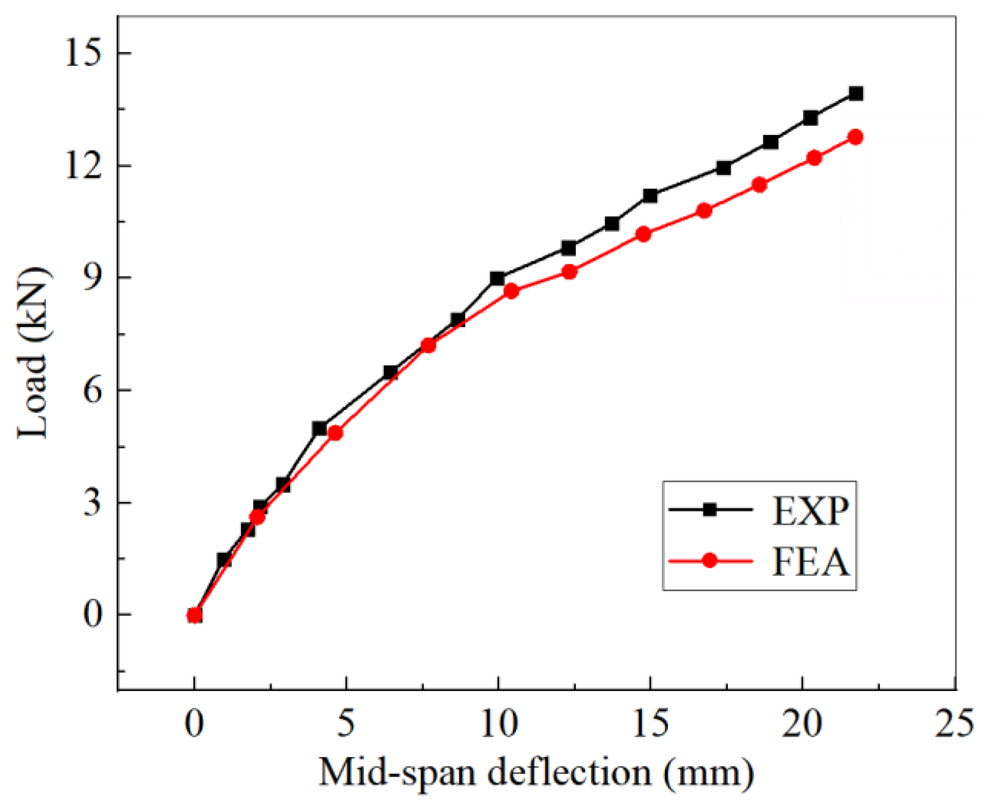
4.4. Verification of FEM

To verify the accuracy of the FEM, Figure 9 presents a comparison between the load-deflection curves obtained from experiments and the finite element analysis. As depicted in Figure 9, it is evident that the finite element results closely match the experimental findings. The finite element analysis indicated that the mid-span displacement was slightly greater than that of the experimental results, with a maximum displacement difference of no more than 10% under equivalent loads. Both curves exhibited a linear increase in proportion during the initial loading stages. When cracks formed at the bottom surface of the slab, the slopes of both curves decreased. In the experiment, the load value at which cracks penetrated the bottom surface of the floor slab was approximately 9.0 kN/m2, while in the FEM, the load value for longitudinal cracks penetrating the bottom of the slab was 8.6 kN/m2. The reason is that cracks in the finite element method were detected when the concrete reached its tensile strength, whereas in the test, cracks were observed visually.
The cracking pattern of the concrete slab was demonstrated through the tensile damage contours, as shown in Figure 12, where the red area could represent the crack development of the concrete [30]. As depicted in Figure 12, the crack distribution characteristics obtained from finite element analysis are similar to those obtained from experiments. Cracks were first observed in the mid-span area and developed diagonally towards the four corners as the load increased. In summary, the developed FEM can reasonably predict the composite slab with a separate joint.

5. Conclusions

This study conducted a static loading test and numerical analysis on a new type of composite slab with a separate joint. The main conclusions are summarized as follows:
(1)
The cracking load of this composite slab with a separate joint was 5.0 kN/m2. When the load increased to 5.5 kN/m2, both the crack width and midspan deflection were below the specified limits for crack width and deflection at the normal serviceability limit state according to the GB50010-2010. This indicates that the composite slab can be employed in different architecture categories, such as residential, commercial, and storage rooms, meeting engineering requirements.
(2)
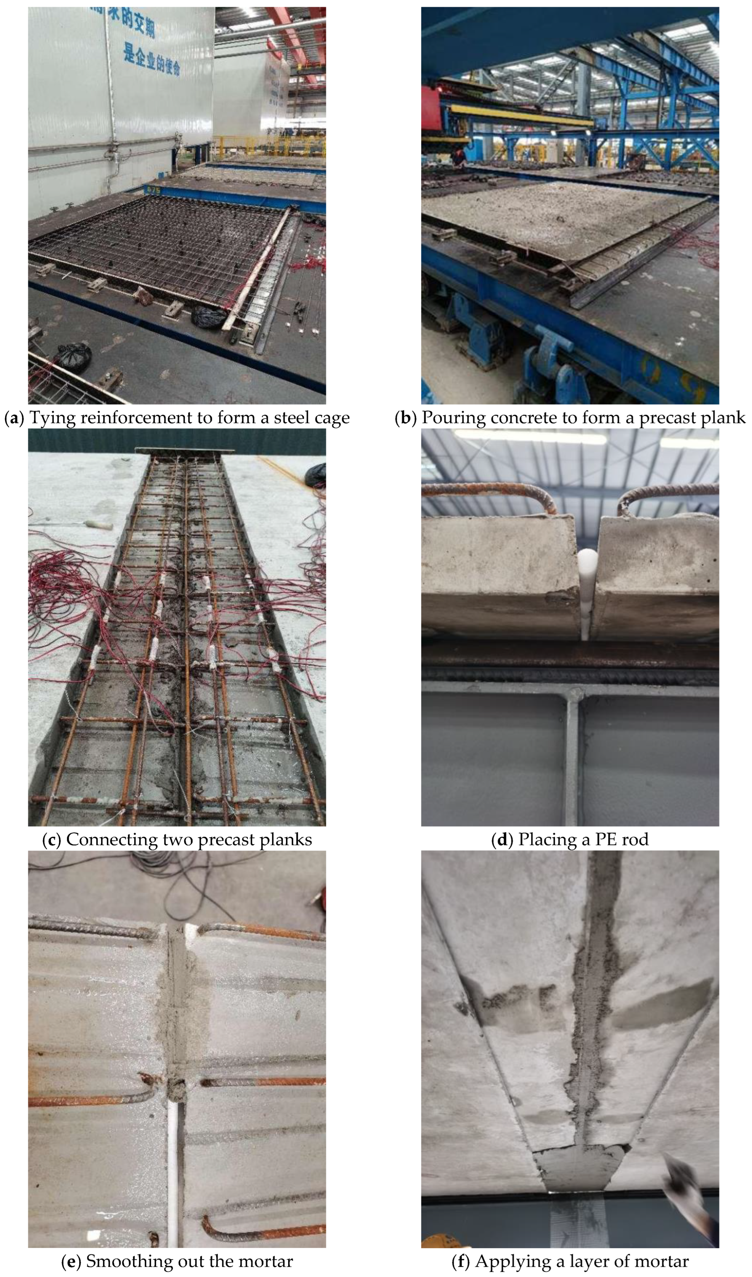
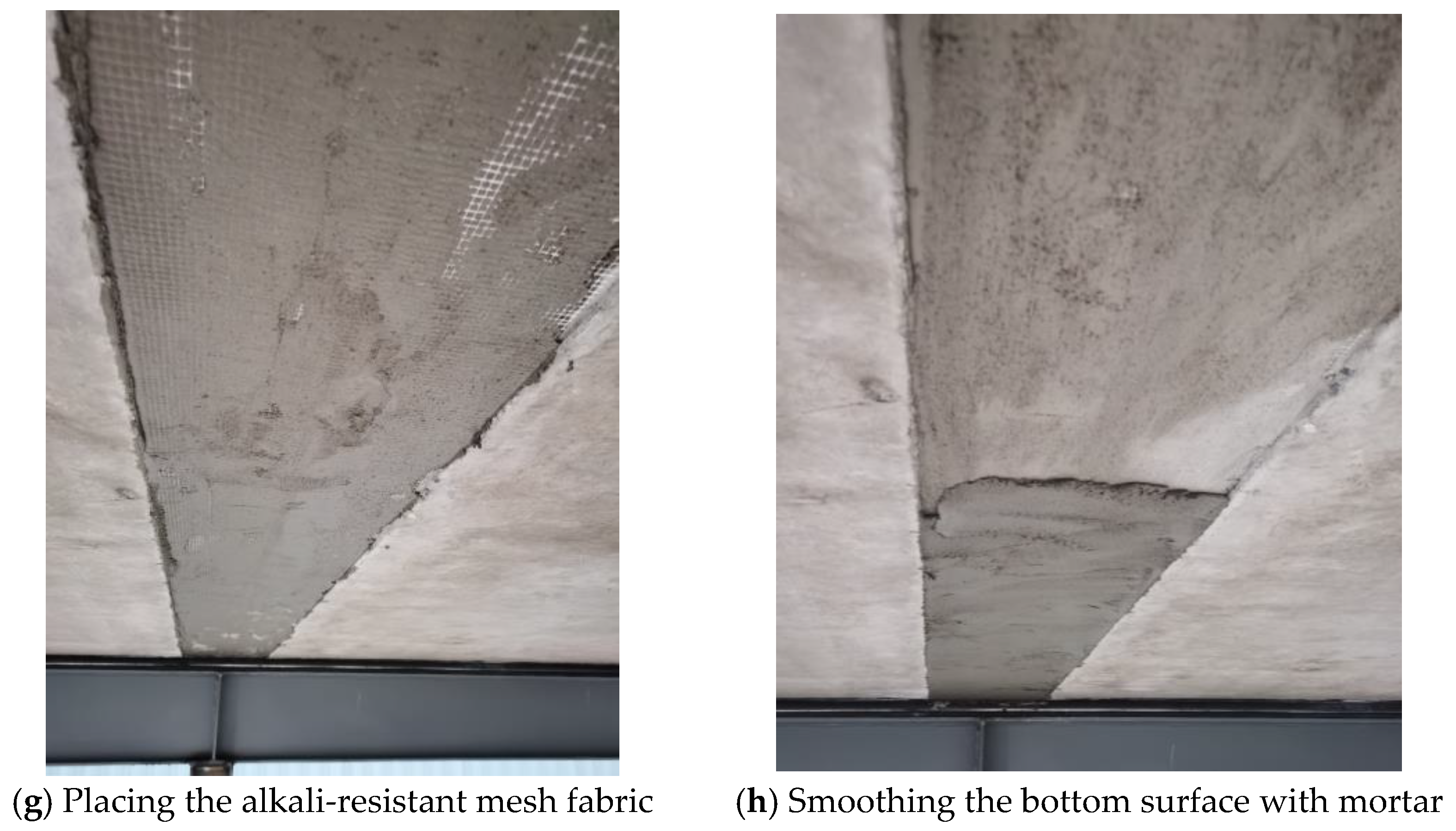
The cracking load at the bottom gap of the composite slab was 5.0 kN/m2, and the cracking load of the precast plank was 6.5 kN/m2. The similar cracking loads of the two indicate that the use of PE rods, mortar, and alkali-resistant mesh fabric can provide sufficient crack resistance.
(3)
When the load was applied to 13.95 kN/m2, the crack width was 0.8 mm and greater than 0.3 mm (the limit value of cracks under the normal service limit state specified in GB50010-2010), indicating that the normal service limit state of this composite slab with a separate joint was controlled by the crack width.
(4)
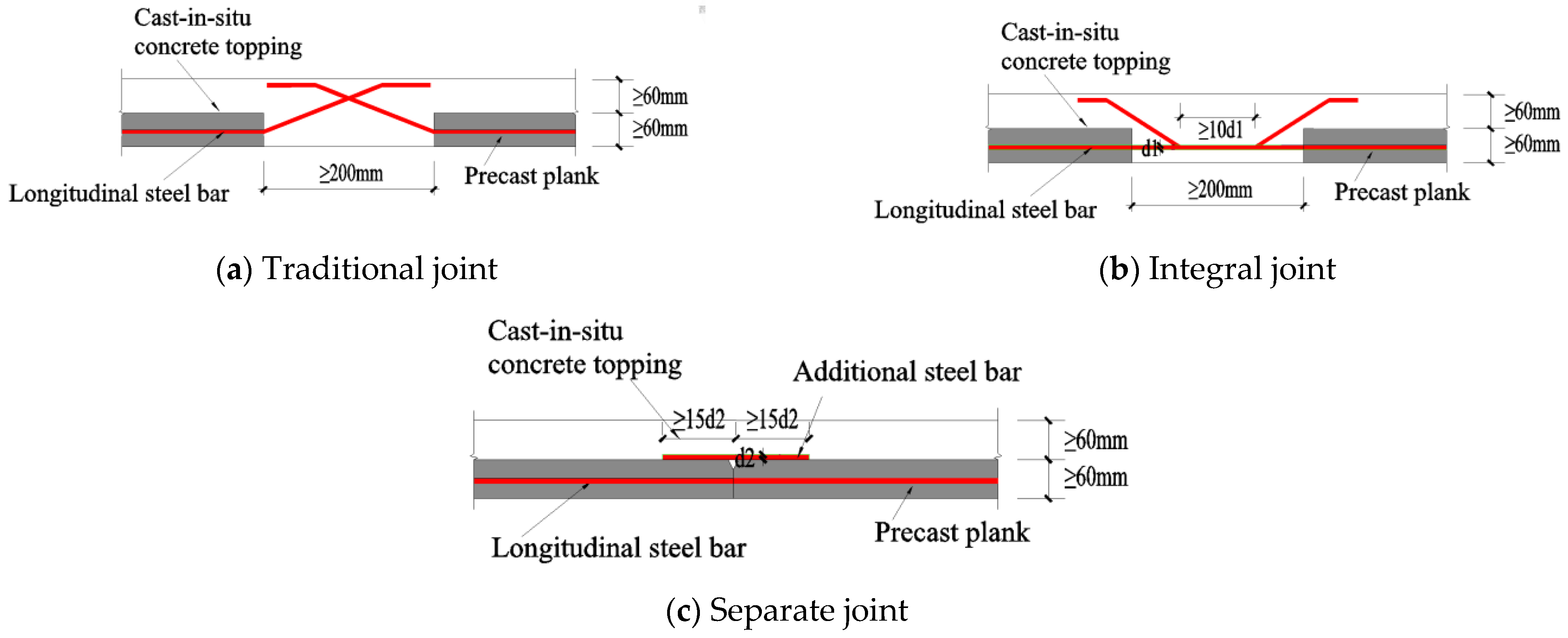
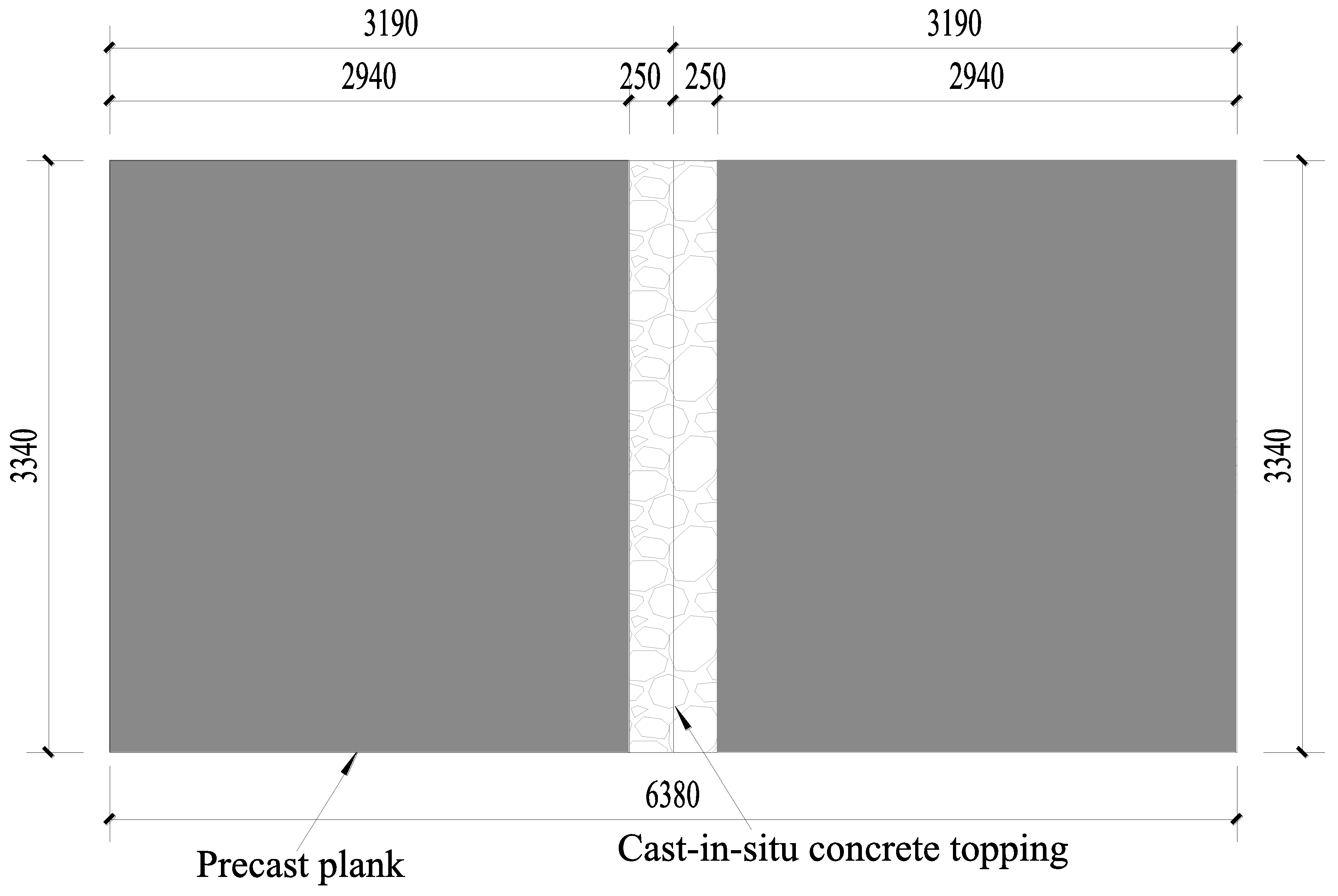
During the entire loading process, there was no significant sliding observed between the precast plank and the concrete topping. Therefore, for the design of the new type of composite slab with a separated joint, it is recommended that the length of the horizontal interface should not be less than 250 mm, and the length of the lap splices should also not be less than 250 mm to ensure the integrity of the joint.
(5)
The finite element model developed in this study can accurately predict the mechanical performance of the new type of composite slab with a separate joint.

Author Contributions

Conceptualization, X.C.; methodology, X.C.; software, X.L.; validation, X.C. and B.L.; formal analysis, X.L.; investigation, X.C.; resources, B.L.; data curation, X.L.; writing—original draft preparation, X.C.; writing—review and editing, X.C. and B.L.; supervision, B.L.; project administration, B.L.; funding acquisition, B.L. All authors have read and agreed to the published version of the manuscript.

Funding

This work was funded by the Huzhou City Science and Technology Plan Project (2021ZD2029).

Data Availability Statement

The original contributions presented in the study are included in the article, further inquiries can be directed to the corresponding author.

Conflicts of Interest

Author Xin Liu was employed by the company Nanjing Dong-Da Modern Prestressed Engineering Co., Ltd. The remaining authors declare that the research was conducted in the absence of any commercial or financial relationships that could be construed as a potential conflict of interest.

References

  1. Park, R. A perspective on the seismic design of precast concrete structures in New Zealand. PCI J. 1995, 40, 40–60. [Google Scholar] [CrossRef]
  2. Chong, X.; Xie, L.L.; Ye, X.G.; Jiang, Q.; Wang, D.C. Experimental study on the seismic performance of superimposed RC shear walls with enhanced horizontal joints. J. Earthq. Eng. 2019, 23, 1–17. [Google Scholar] [CrossRef]
  3. Nie, J.G.; Jiang, Y.X.; Nie, X.; Zhuang, L.D. Effect of truss reinforcement on mechanical properties of prefabricated slabs. J. Build. Struct. 2021, 42, 151–158. [Google Scholar]
  4. Lou, F.; Chen, X.L.; Luo, B.; Chen, Z. Mechanical behavior of a new type of reinforced concrete composite slab with a joint. Case. Stud. Constr. Mater. 2024, 20, e02773. [Google Scholar]
  5. Yun, Y.C.; Jiang, J.F.; Chen, P. Flexural behavior of lattice girder slabs with different connections: Experimental study. Adv. Civ. Eng. 2022, 2022, 7722668. [Google Scholar] [CrossRef]
  6. Wu, F.B.; Liu, B.; Li, J.; Deng, L.B.; Huang, L. Experimental study and finite element analysis of structural measures for joints between new type of superposed slabs. Ind. Constr. 2015, 45, 50–56+75. [Google Scholar]
  7. Ye, X.G.; Hua, H.G.; Xu, T.S.; Wang, D.C. Experimental study on connections of superimposed slabs. Ind. Constr. 2010, 40, 59–63. [Google Scholar]
  8. Ye, X.G.; Yang, K.N.; Chong, X. Experimental study on properties of side joint between superimposed slabs with lattice steel bars. Appl. Mech. Mater. 2014, 638, 109–114. [Google Scholar]
  9. Wang, Y.R. Experiment Study and Numerical Simulation Analysis on Bending Performance of Side Stitched Reinforced Concrete Superimposed Slab. Master’s Thesis, Hefei University of Technology, Hefei, China, 2014. [Google Scholar]
  10. Liu, Y.L.; Huang, J.Q.; Chong, X.; Ye, X.G. Experimental investigation on flexural performance of semi-precast reinforced concrete one-way slab with joint. Struct. Concr. 2021, 22, 2243–2257. [Google Scholar] [CrossRef]
  11. Yu, Y.T.; Zhao, Y.; Gao, Z.Q. Experimental research on flexural behavior of reinforced concrete composite slab connected without gap. J. Build. Struct. 2019, 49, 29–37. [Google Scholar]
  12. Xiao, T.; Zhang, M.S.; Li, B.Y.; Xu, Q.B.; Gong, S.F. Experimental study on flexural performance of composite slab with groove splicing joint. J. Zhejiang Univ. 2023, 57, 842–854. [Google Scholar]
  13. Kim, D.W.; Shim, C.S. Crack width control on concrete slab using half-depth precast panels with loop joints. J. Korean. Soc. Civ. Eng. 2015, 35, 19–29. [Google Scholar] [CrossRef]
  14. Zhang, X.F.; Li, H.M.; Liang, S.X.; Zhang, H. Experimental and numerical study of lattice girder composite slabs with monolithic joint. Crystals 2021, 11, 219. [Google Scholar] [CrossRef]
  15. Zhang, X.F.; Zheng, S.G.; Shan, Y.C.; Zhou, X.Y.; Chen, D. Experimental study on full-scale steel bar truss superimposed two-way slabs without extending reinforcement on all sides and connected without gap. Build. Struct. 2019, 49, 83–87. [Google Scholar]
  16. Stehle, J.; Kanellopoulos, A.; Karihaloo, B.L. Performance of joints in reinforced concrete slabs for two-way spanning action. Proc. ICE-Struct. Build. 2011, 164, 197–209. [Google Scholar] [CrossRef]
  17. Altoubat, S.; Ousmane, H.; Barakat, S. Experimental study of in-plane shear behavior of fiber-reinforced concrete composite slabs. J. Struct. Eng. 2016, 142, 1–11. [Google Scholar] [CrossRef]
  18. JGJ1-2014; Technical Specification for Precast Concrete Structures. China Architecture & Building Press: Beijing, China, 2014.
  19. GB/T 50081-2019; Standard for Test Method of Concrete Physical and Mechanical Properties. China Architecture & Building Press: Beijing, China, 2019.
  20. GB/T 228.1-2010; Metallic Materials: Tensile Testing: Part 1: Method of Test at Room Temperature. Standards Press of China: Beijing, China, 2010.
  21. GB/T 50152-2012; Standard for Test Method of Concrete Structures. Architecture & Building Press: Beijing, China, 2012.
  22. GB5009-2012; Load Code for the Design of Building Structures. Architecture & Building Press: Beijing, China, 2012.
  23. GB50010-2010; Code for Design of Concrete Structures. Architecture & Building Press: Beijing, China, 2010.
  24. Genikomsou, A.S.; Polak, M.A. Finite element analysis of punching shear of concrete slabs using damaged plasticity model in ABAQUS. Eng. Struct. 2015, 98, 38–48. [Google Scholar] [CrossRef]
  25. Sidoroff, F. Physic Nonlinearities in Structural Analysis; Springer: Berlin/Heidelberg, Germany, 1981. [Google Scholar]
  26. Liu, J.P.; Lai, Z.C.; Chen, B.C.; Xu, S. Experimental behavior and analysis of steel-laminated concrete (RC and UHPC) composite girders. Eng. Struct. 2020, 225, 111240. [Google Scholar] [CrossRef]
  27. ACI. Building Code Requirements for Structural Concrete and Commentary; ACI Committee: Hong Kong, China, 1995; p. 318. [Google Scholar]
  28. Luo, B. Research on Designing Theory and Experimental among Flexural Performance of Precast Concrete Composite Slabs with Different Shapes. Ph.D. Thesis, Xi’an University of Architecture and Technology, Xi’an, China, 2019. [Google Scholar]
  29. Ma, X. Experimental Study on Flexural Behavior of Long-Span Laminated Slabs with Precast Composite Panel. Master’s Thesis, Xi’an University of Architecture and Technology, Xi’an, China, 2020. [Google Scholar]
  30. Chen, A.; Yossef, M.; Hopkins, P. A comparative study of different methods to calculate degrees of composite action for insulated concrete sandwich panels. Eng. Struct. 2020, 212, 110423. [Google Scholar] [CrossRef]
Figure 1. The precast plank of the new type of composite slab.
Buildings 14 01890 g001
Figure 2. The common types of joint configurations for composite slabs in China.
Buildings 14 01890 g002
Figure 3. Geometric dimensions of the composite slab with a separated joint.
Buildings 14 01890 g003
Figure 4. Reinforcement arrangement of the precast plank.
Buildings 14 01890 g004
Figure 5. The details of the separate joint.
Buildings 14 01890 g005
Figure 6. The manufacturing process of the composite slab with a separate joint.
Buildings 14 01890 g006aBuildings 14 01890 g006b
Figure 7. Loading device.
Buildings 14 01890 g007
Figure 8. Distribution of cracks on the bottom surface.
Buildings 14 01890 g008
Figure 9. The load-deflection curve.
Buildings 14 01890 g009
Figure 10. Uniaxial stress–strain curve for the steel bar.
Buildings 14 01890 g010
Figure 11. The FEM of the specimen.
Buildings 14 01890 g011
Figure 12. Distribution of tensile damage on the bottom surface of the composite slab.
Buildings 14 01890 g012
Table 1. Compressive strengths of the concrete cubes.
ConcreteNo.Compressive Strength/MPaAverage Compressive Strength/MPa
Precast plank137.338.0
238.7
338.0
Cast-in situ concrete topping446.646.0
546.2
645.2
Table 2. Material properties of steel bars.
MemberDiameter (d)/mmElastic Modulus (Es)/GPaYielding Strength (fy)/MPaUltimate Strength (fu)/MPa
Steel bars8196525688.5
Table 3. Loading values for each stage of the test.
Loading StageIncrement of Load per Stage (kN/m2)Total Accumulated Load Value (kN/m2)Loading StageIncrement of Load per Stage (kN/m2)Total Accumulated Load Value (kN/m2)
00081.19
11.51.590.829.82
20.82.3101.4710.47
30.62.9110.7511.22
40.63.5120.7511.97
51.55130.7512.65
61.56.5140.6813.3
71.47.9150.6513.95
Table 4. Deflection and crack patterns of the slab under different quasi-permanent load combinations.
Architecture CategoriesFp (kN/m2)Δ/mmCrack Characteristics
Residential buildings2.31.74Concrete not cracked
Shops3.252.60Concrete not cracked
Storage rooms5.54.88Concrete cracking with crack width less than 0.3 mm
Disclaimer/Publisher’s Note: The statements, opinions and data contained in all publications are solely those of the individual author(s) and contributor(s) and not of MDPI and/or the editor(s). MDPI and/or the editor(s) disclaim responsibility for any injury to people or property resulting from any ideas, methods, instructions or products referred to in the content.

