
Research Progress on Shear Characteristics and Rapid Post-Disaster Construction of Narrow-Width Steel Box–UHPC Composite Beams

Abstract
1. Introduction
2. Overview of Shear Resistance Tests of Narrow-Width Steel Box–UHPC Composite Beams
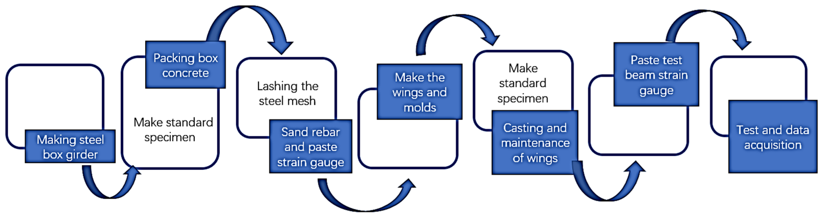
2.1. Preparations for Experiments
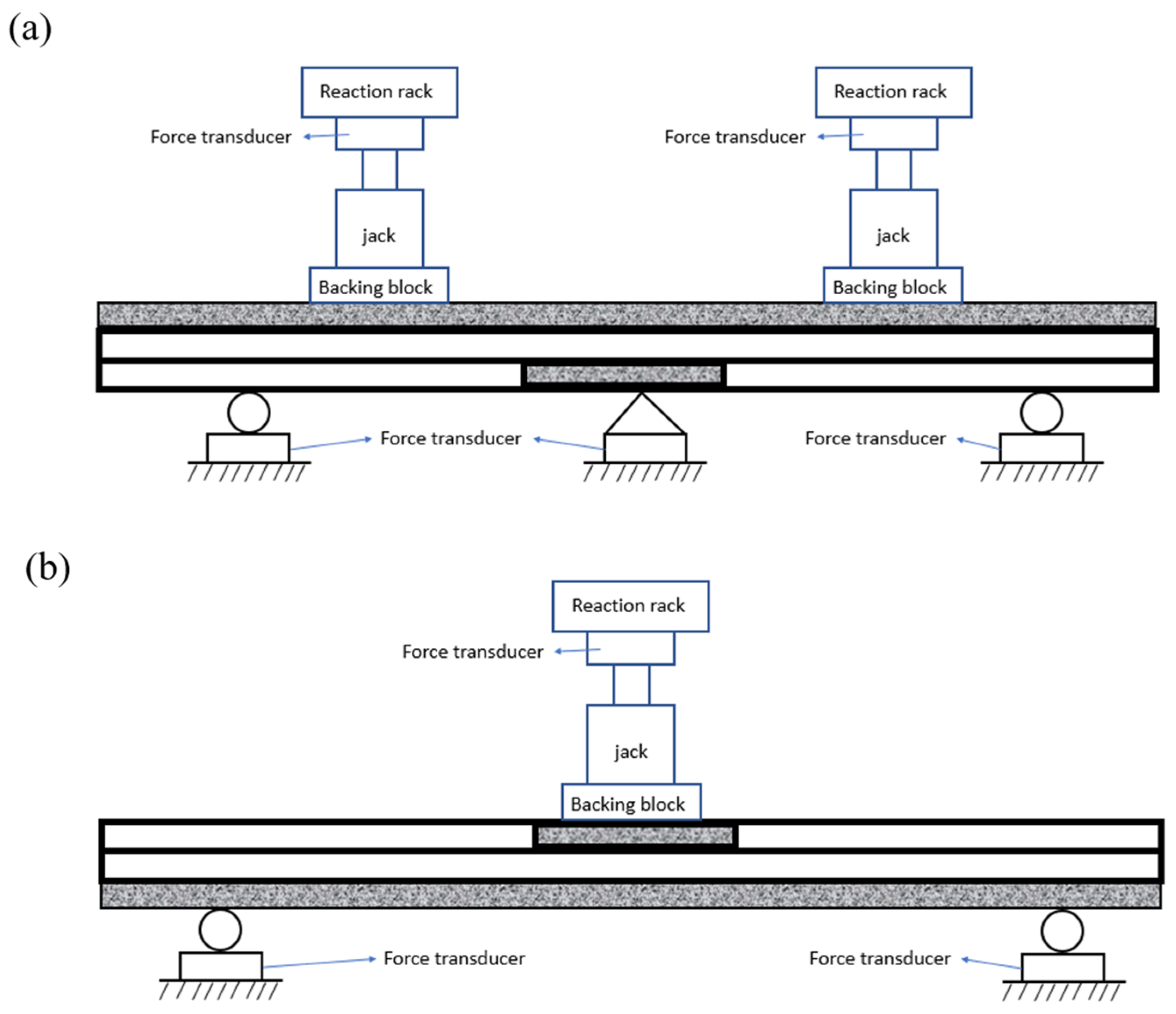
2.2. Experimental Tests
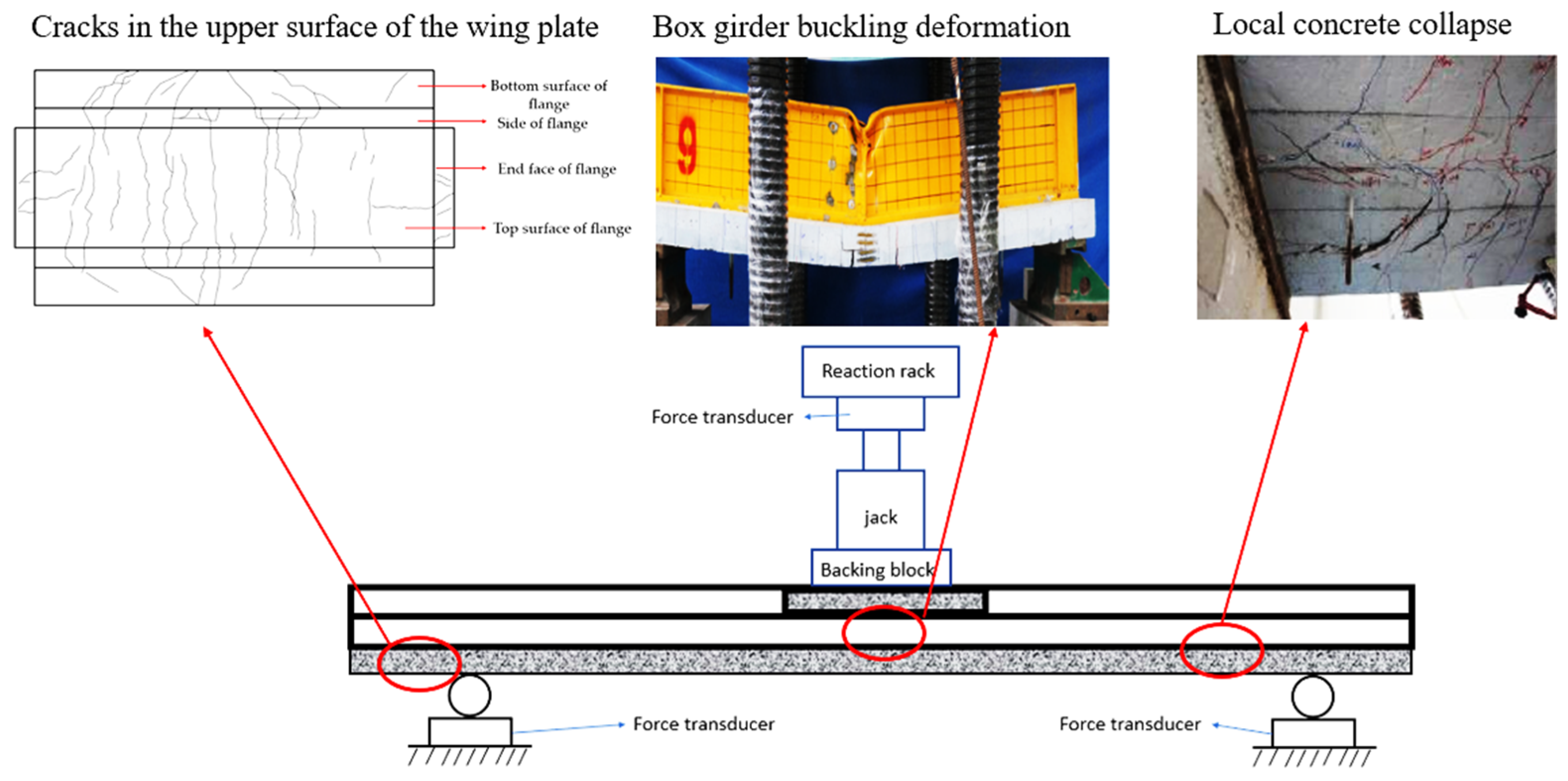
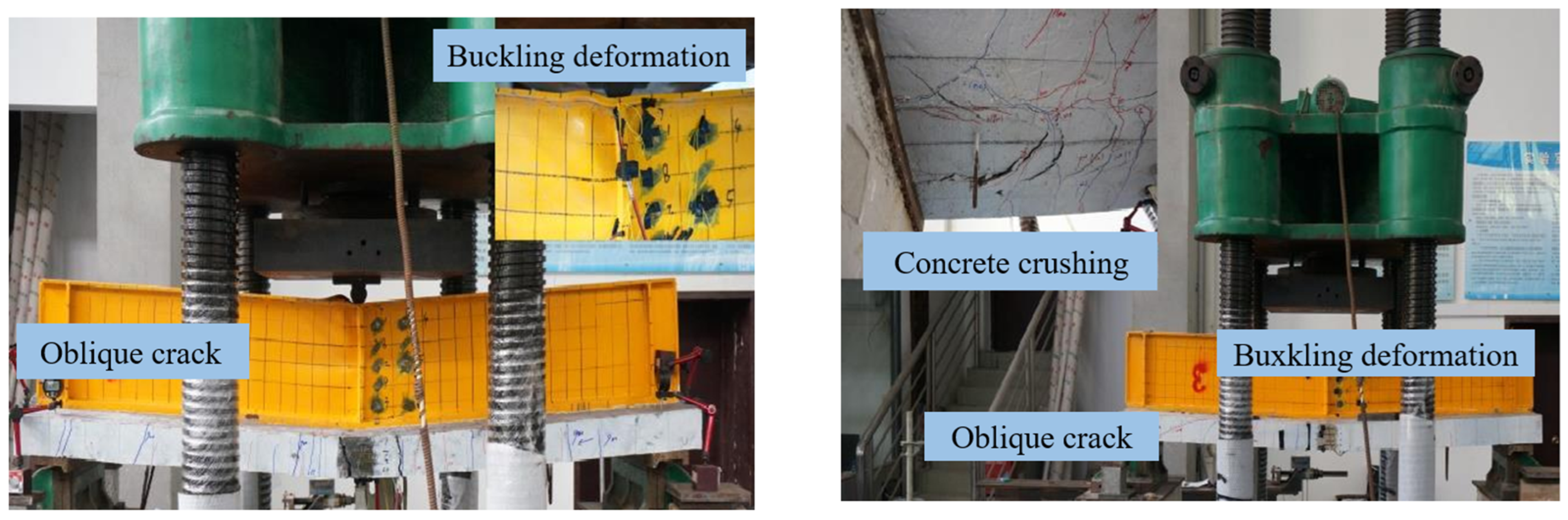
2.3. Failure Modes
- (1)
- Elastic stage (V < Vy)
- (2)
- Elastoplastic stage (Vy < V < VU)
- (3)
- Plastic stage
- (4)
- Failure stage
3. Review of the Shear Code Guidelines and Analysis of the Influencing Factors in the Negative Moment Zone of the Narrow-Width Steel Box–UHPC Composite Beam
3.1. Specification Guidelines for Shear Resistance in the Negative Moment Zone
- (1)
- American AASHTO specification [58]
- (2)
- European specification EC4 [59]
- (3)
- Chinese Code for the Design of Steel–Concrete Composite Bridges [60]
3.2. Examination of the Experimental Results of the Narrow-Width Steel Box–UHPC Composite Beam
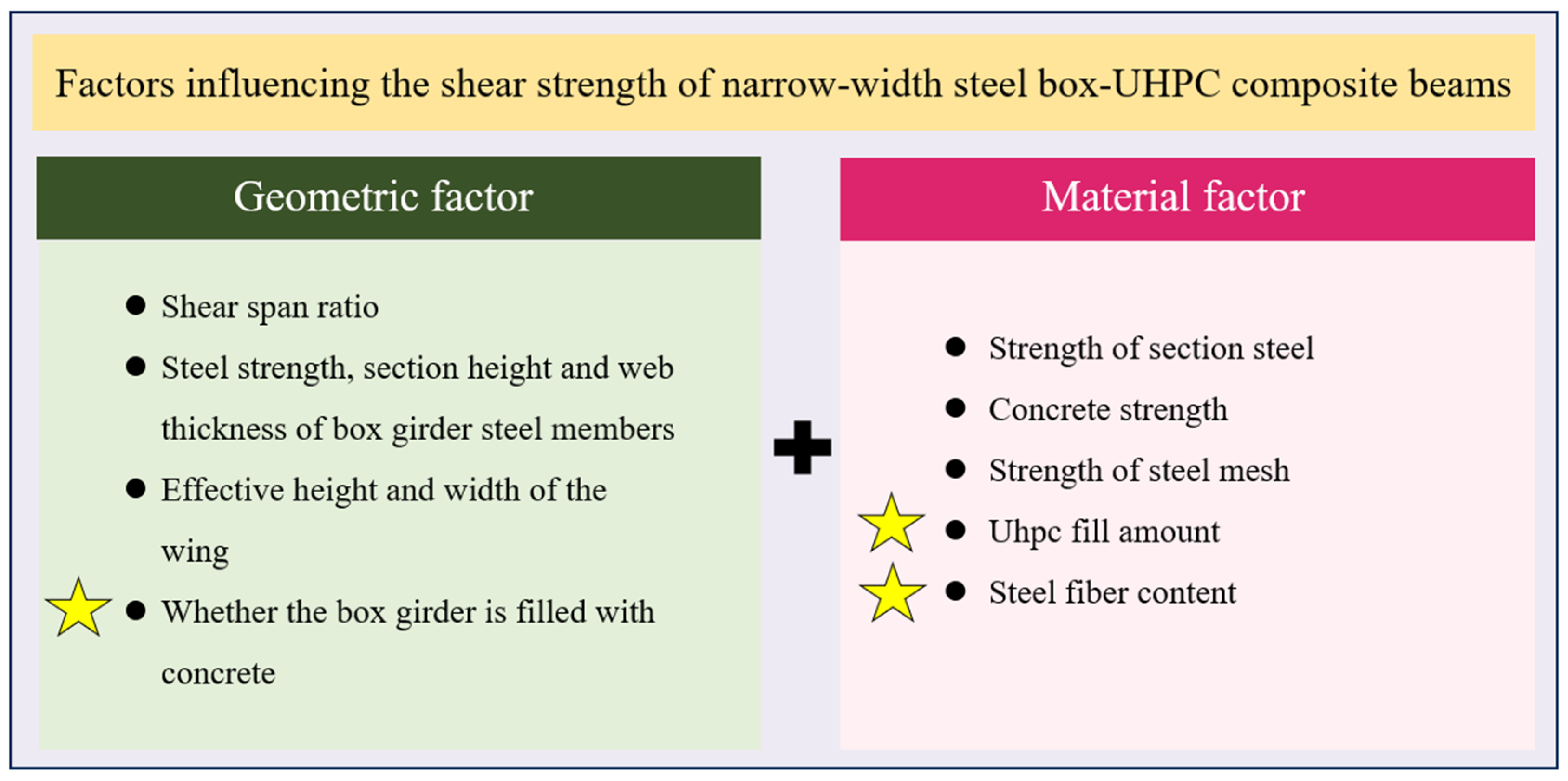
3.3. Analysis of the Influencing Factors on the Shear Strength of the Narrow-Width Steel Box–UHPC Composite Beam
- (1)
- Shear span ratio
- (2)
- Steel box girder
- (3)
- Concrete wing slab
- (1)
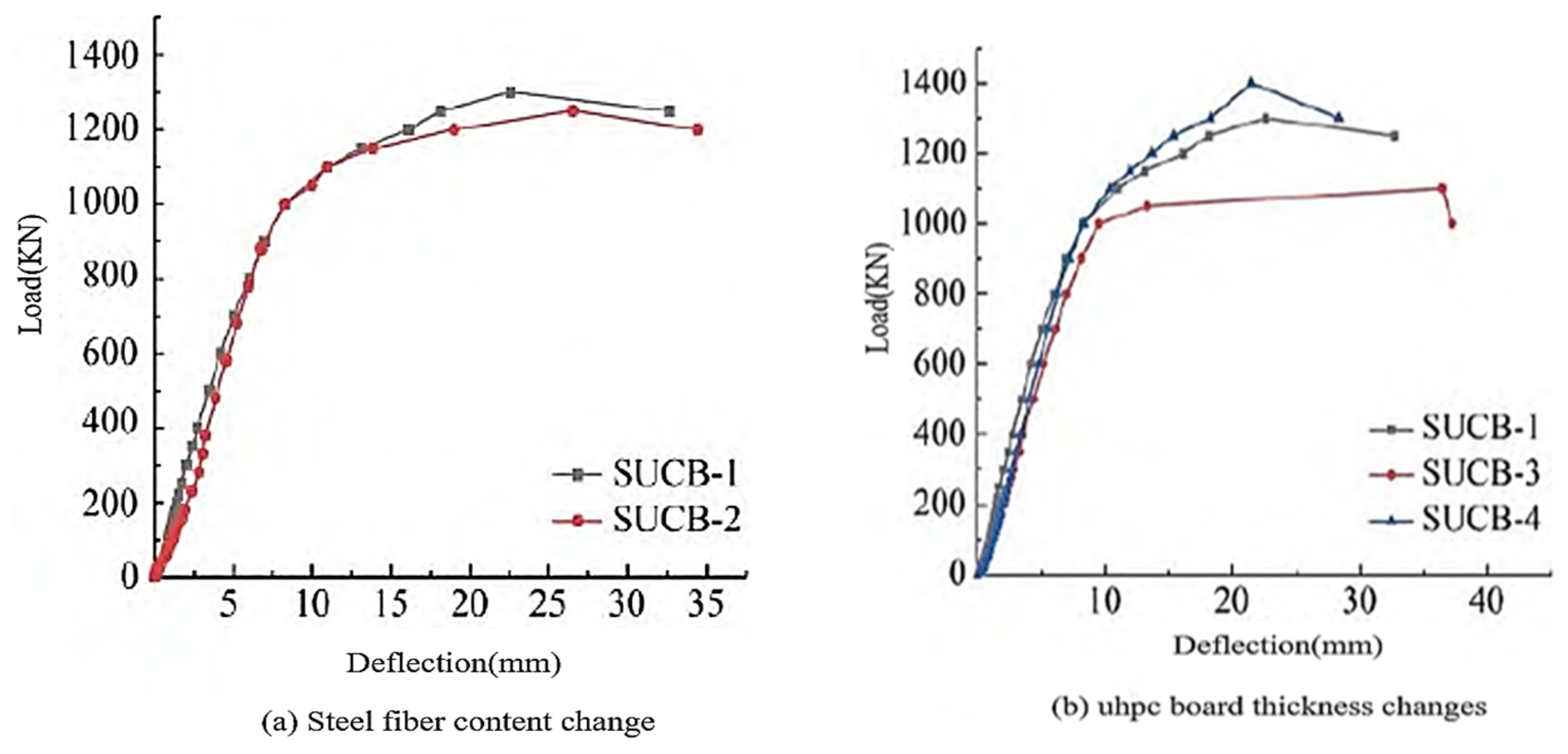
- UHPC steel fiber content
- (2)
- UHPC board thickness
- (3)
- Filling concrete
- (4)
- Transverse partition in the box
- (5)
- Crossbeam between boxes
- (6)
- Shear connector

| References | Box Girder Concrete Filling Height/Box Girder Height | Box Girder Concrete Strength (MPa) | UHPC Wing/Wing Thickness | Loading Protocol | Comments |
|---|---|---|---|---|---|
| Zhu et al. [68] | 0 | n/a | 1 | The formal loading starts at 0. Before the loading force reaches 500 kN, force-controlled loading is adopted, with 25 kN per stage. | The tribute of UHPC fins against the shear capacity is about 50%, and the bridge function of UHPC fin–steel fiber is good. |
| Chen et al. [69] | 1 | 65 | 1 | The formal loading starts at 0. Before the loading force reaches 500 kN, force-controlled loading is adopted, with 25 kN per stage. After the loading force reaches 500 kN, displacement-controlled loading is adopted. | The tribute of UHPC fins against the shear capacity is about 50%, and the bridge function of UHPC fin–steel fiber is good. Effectively reduce wing cracking |
| Xue et al. [70] | 1 | 44.3 | 0 | Through force-controlled loading, the preload is 20, 40, and 60 kN. | Two continuous composite beam specimens were studied, and the results show that the double combination can inhibit the crack development of the concrete wing slab during the loading stage. |
| Liu et al. [71] | 1 | 0 0.1 | Monotonic static loading | The shear-bearing capacity of the steel–composite beam under negative bending moments is borne by the steel beam and concrete wing slab. | |
| Al-Osta [72] | 1 | 54 | n/a | The loading process is divided into three stages: preloading, force-controlled loading, and displacement-controlled loading. | A formula for calculating the shear strength of UHPC–NC (Normal Concrete) composite beams was obtained. The method can effectively reflect the influence of various parameters such as the UHPC layer, reinforcement of the UHPC layer, and the size effect on the shear capacity of UHPC–NC composite beams. |
| Hussein [61] | 1 | 52 | n/a | Force control | Both the bonding UHPC prefabricated slab and the cast-in-place gouge UHPC layer can effectively improve the bearing capacity of the composite structure, but the cast-in-place gouge casting method is superior to the bonding of the prefabricated slab. |
4. Progress of the Rapid Construction Technology of the Narrow-Width Steel Box–UHPC Composite Beam after a Disaster
4.1. Double-Narrow Steel Box Girder
4.2. Three-Narrow Steel Box Girder
4.3. Anti-Crack Control Measures of the Negative Bending Moment of the Fulcrum in the Narrow-Width Steel Box Continuous Beam with a Long Span
4.4. Narrow-Width Steel Box Girder Application Scenarios
- (1)
- Small-radius flat-curved bridge or widened-ramp bridge in an interworking area with a span of 30 m or more
- (2)
- The main-line 60 ~ 100 m span of a mountain or an urban bridge
5. Discussion and Design Suggestions
6. Conclusions and Perspective
- Due to technological advancements in the use of high-strength materials and the increasing number of modern structures using concrete of high strength, some restrictions on narrow-width steel box–UHPC composite beams in the design specification need to be updated. In this paper, the Chinese code GB 50917-2013, the European code EC4, and the American code AASHTO are reviewed. The results show that the calculated values of the shear strength obtained by the above three codes are too conservative, and the predicted values of the shear strength obtained are less than 70% of the actual shear strength, resulting in a waste of shear strength. The calculation method of shear force based on the principle of superimposed shear capacity is not complete and lacks relatively complete and applicable calculation criteria.
- According to the literature review, the main failures of UHPC composite beams under the condition of the negative moment zone are buckling deformation of the box girder, cracks on the upper surface of wing plates, and local concrete crushing. The main factors affecting the shear strength of the composite beam structure are shear span ratio, concrete wing plate, UHPC steel fiber content, UHPC plate thickness, and transverse partition in the box. The formula for calculating the shear capacity of a narrow-width steel box girder based on the superposition principle of shear capacity lacks a uniform conclusion regarding its applicability and needs further study.
- The new double-narrow steel box girder structure and three-narrow steel box girder structure have a good application effect in the reconstruction of bridges after a disaster. For the long-span continuous beam bridge, the narrow steel box composite structure needs to use corresponding control measures to reduce the development of cracks at the middle support. At the same time, the scope of the application of the narrow-width steel box girder composite bridge is reviewed, and the conclusion is that the narrow-width steel box girder is mainly used in small-radius flat-curved bridges or widened-ramp bridges in interworking areas with a span of 30 m or more and in the main-line 60–100 m span in mountainous or urban areas.
- The steel–concrete composite structure, with advantages in all aspects, has a wide range of applications in housing construction and large road and bridge construction. The construction method combined with narrow-width steel box–UHPC composite beams can be used to quickly rebuild bridges under poor construction environments after an earthquake, which is of great significance for post-disaster reconstruction projects.
Author Contributions
Funding
Data Availability Statement
Conflicts of Interest
References
- Meng, B.; Xiong, Y.P.; Zhong, W.H.; Duan, S.C.; Li, H. Progressive collapse behavior of composite substructure with large rectangular beam-web openings. Eng. Struct. 2023, 295, 116861. [Google Scholar] [CrossRef]
- Gerasimidis, S.; Ellingwood, B. Twenty Years of Advances in Disproportionate Collapse Research and Best Practices since 9/11/2001. J. Struct. Eng. 2023, 149, 2. [Google Scholar] [CrossRef]
- Fan, H.B.; Liu, T.; Zhang, S.Y.; He, H.J.; Zhu, Z.G.; Zhu, Y.Q.; Gao, X.Q. Effects of Jet-Grouting Piles on Loess Tunnel Foundation with Centrifugal Model Tests. Int. J. Geomech. 2023, 23, 3. [Google Scholar] [CrossRef]
- Fang, Q.; Liu, X.; Zeng, K.H.; Zhang, X.D.; Zhou, M.Z.; Du, J.M. Centrifuge modeling of tunnelling below existing twin tunnels with different types of support. Undergr. Space 2022, 7, 1125. [Google Scholar] [CrossRef]
- Jin, Z.X.; Zhang, C.P.; Li, W.; Tu, S.Q.; Wang, L.B.; Wang, S.X. Stability analysis for excavation in frictional soils based on upper bound method. Comput. Geotech. 2024, 165, 105916. [Google Scholar] [CrossRef]
- Qiu, J.L.; Liu, Y.H.; Qian, X.Y.; Ma, C.; Liu, J.; Liu, T.; Han, H.X.; Ma, P.G. Guarantee rate statistics and product-moment correlation analysis of the optimal deformation allowance for loess tunnel in China. Environ. Earth Sci. 2024, in press. [Google Scholar]
- Li, Z.Q.; Lai, J.X.; Ren, Z.D.; Shi, Y.F.; Kong, X.G. Failure mechanical behaviors and prevention methods of shaft lining in China. Eng. Fail. Anal. 2023, 143, 106904. [Google Scholar] [CrossRef]
- Qiu, J.L.; Liu, D.D.; Zhao, K.; Lai, J.X.; Wang, X.L.; Wang, Z.C.; Liu, T. Influence spatial behavior of surface cracks and prospects for prevention methods in shallow loess tunnels in China. Tunn. Undergr. Space Technol. 2024, 143, 105453. [Google Scholar] [CrossRef]
- Tu, S.Q.; Li, W.; Zhang, C.P.; Chen, W. Effect of inclined layered soils on face stability in shield tunneling based on limit analysis. Tunn. Undergr. Space Technol. 2023, 131, 104773. [Google Scholar] [CrossRef]
- Tu, S.Q.; Li, W.; Zhang, C.P.; Wang, L.B.; Jin, Z.X.; Wang, S.X. Seepage effect on progressive failure of shield tunnel face in granular soils by coupled continuum-discrete method. Comput. Geotech. 2024, 166, 106009. [Google Scholar] [CrossRef]
- Wang, Z.C.; Cai, Y.C.; Xie, Y.L.; Zhang, M.Z.; Lai, J.X.; Qiu, J.L.; Liu, T. Laboratory study on mechanical behavior of hollow p-type steel-concrete composite support in loess tunnel. Tunn. Undergr. Space Technol. 2023, 141, 105280. [Google Scholar] [CrossRef]
- Wu, K.; Zheng, X.M.; Zhao, N.N.; Shao, Z.S. Effect of compressible layer on time-dependent behavior of soft-rock large deformation tunnels revealed by mathematical analytical method. Appl. Math. Model. 2024, 126, 457. [Google Scholar] [CrossRef]
- Xu, S.S.; Lai, J.X.; O’kelly, B.C.; Zhao, B.D. 3D deformation and strain fields in drying kaolinite obtained from tracking internal bubbles using X-ray CT and ANN. Acta Geotech. 2024, 19, 99. [Google Scholar] [CrossRef]
- Xu, S.S.; Nowamooz, H.; Lai, J.X.; Liu, H.T. Mechanism, influencing factors and research methods for soil desiccation cracking: A review. Eur. J. Environ. Civ. Eng. 2023, 27, 3091. [Google Scholar] [CrossRef]
- Yuan, P.L.; Zhang, B.D.; Yang, Y.T.; Jiang, T.F.; Li, J.; Qiu, J.L.; He, H.J. Application of polymer cement repair mortar in underground engineering: A review. Case Stud. Constr. Mater. 2023, 19, e02555. [Google Scholar] [CrossRef]
- Zan, W.B.; Liu, L.J.; Lai, J.X.; Wang, E.B.; Zhou, Y.P.; Yang, Q. Deformation failure characteristics of weathered phyllite tunnel and variable-stiffness support countermeasures: A case study. Eng. Fail. Anal. 2023, 153, 107553. [Google Scholar] [CrossRef]
- Liu, Y.H.; Qian, X.Y.; Qiu, J.L.; Chen, Y.H.; Liu, T.; Zhao, K.; Sun, H.; Liu, D.D. Disaster Analysis and Protection Measures of Coal and Gas Outburst for Coal Measures Strata Gas Tunnel in China. KSCE J. Civ. Eng. 2024; in press. [Google Scholar]
- Zhao, Z.Z.; Sun, H.; Zhang, N.X.; Xing, T.H.; Cui, G.H.; Lai, J.X.; Liu, T.; Bai, Y.B.; He, H.J. Application of unmanned aerial vehicle tilt photography technology in geological hazard investigation in China. Nat. Hazards 2024. [Google Scholar] [CrossRef]
- Bekic, D.; Kerin, I.; Cahill, P.; Michalis, P.; Lapthorne, J.; Solman, H.; Gilja, G.; Potocki, K.; Pakrashi, V.; McKeogh, E. In BRIDGE SMS—INNOVATIVE SOLUTION FOR MANAGEMENT OF BRIDGES OVER WATER. In Proceedings of the 5th International Conference on Road and Rail Infrastructure (CETRA), Zadar, Croatia, 17–19 May 2018; pp. 57–63. [Google Scholar]
- Niemierko, A. Modern bridge bearings and expansion joints for road bridges, 6th Transport Research Arena (TRA), Warsaw, Poland, April 18-21, 2016. Transp. Res. Procedia 2016, 14, 4040–4049. [Google Scholar] [CrossRef]
- Tang, K.; Liu, D.; Xie, S.; Qiu, J.; Lai, J.; Liu, T.; Fang, Y. Analysis of loess water migration regularity and failure response of tunnel structure under rainfall environment. Bull. Eng. Geol. Environ. 2024, 83, 251. [Google Scholar] [CrossRef]
- Zhang, Z.; Song, Z.; Lai, J.; Qiu, J.; Cheng, Y.; Zhang, J. Critical slowing down precursor information for the acoustic emission response characteristics of defective tuffs. Theor. Appl. Fract. Mech. 2024, 129, 104220. [Google Scholar] [CrossRef]
- Li, Z.H.; Ma, E.L.; Lai, J.X.; Su, X.L. Tunnel deformation prediction during construction: An explainable hybrid model considering temporal and static factors. Comput. Struct. 2024, 294, 107276. [Google Scholar] [CrossRef]
- Zan, W.B.; Lai, J.X.; Zhang, W.J.; Yang, Q.; Qin, Y.W.; Su, X.L. Experimental and applied research on similar materials to granular mixtures for the solid-liquid coupling model test of an underwater tunnel. Constr. Build. Mater. 2024, 416, 135170. [Google Scholar] [CrossRef]
- Qin, Y.W.; Chen, Y.H.; Lai, J.X. Failures in Loess Slope-Tunnel System: An overview of trigging sources, acting mechanism and mitigation strategies. Eng. Fail. Anal. 2024, 158, 107996. [Google Scholar] [CrossRef]
- Li, Z.; Lai, J.; Wang, M.; Qiu, J.; Zan, W. Collapse mechanism and treatments of a deep tunnel in the weathered granite fault zone. Tunn. Undergr. Space Technol. 2024, 152, 105891. [Google Scholar] [CrossRef]
- Mao, M.; Yin, C.L.; Shen, S.Y.; Wan, Y. Experimental and Numerical Study on Flexural Behaviors of Steel-UHPC Composite Beams under Hogging Moment. Ksce J. Civ. Eng. 2024, 28, 2344–2354. [Google Scholar] [CrossRef]
- Ataei, A.; Zeynalian, M.; Yazdi, Y. Cyclic behaviour of bolted shear connectors in steel-concrete composite beams. Eng. Struct. 2019, 198, 109455. [Google Scholar] [CrossRef]
- Lu, X.Z.; Zhang, L.; Lin, K.Q.; Li, Y. Improvement to composite frame systems for seismic and progressive collapse resistance. Eng. Struct. 2019, 186, 227. [Google Scholar] [CrossRef]
- Romero, M.L.; Espinós, A. Advances in Steel-Concrete Composite Structures (ASCCS 2018). Structures 2019, 21, 1. [Google Scholar] [CrossRef]
- Zhang, Z.J.; Liu, Y.J.; Liu, J.; Xin, G.F.; Long, G.X.; Zhang, T.T. Experimental study and analysis for the long-term behavior of the steel-concrete composite girder bridge. Structures 2023, 51, 1305. [Google Scholar] [CrossRef]
- Saiidi, M.; Douglas, B.; Feng, S. Prestress Force Efect on Vibration Frequency of Concrete Bridges. J. Struct. Eng. 1994, 12, 2233. [Google Scholar] [CrossRef]
- Mcginnis, M.J.; Pessiki, S.; Turker, H. Application of Three-dimensional Digital Image Correlation to the Core—Drilling Method. Soc. Exp. Mech. 2005, 4, 359. [Google Scholar] [CrossRef]
- Liu, S.; Wang, B.H.; Zheng, Y.; Mo, S.X.; Zhang, Q.Y.; Zhou, P.X. Experimental and Computational Research on the Shear Performance of Partially Filled Narrow-Width Steel Box-UHPC-Combined Girders under Negative Moment Action. Buildings 2023, 13, 2749. [Google Scholar] [CrossRef]
- Wang, Y.C. Performance of steel-concrete composite structures in fire. Prog. Struct. Eng. Mater. 2005, 7, 86. [Google Scholar] [CrossRef]
- Benedetty, C.A.; Santos, V.B.D.; Krahl, P.A.; Rossi, A.; de Andrade Silva, F.; Cardoso, D.C.T.; Martins, C.H. Flexural and shear behavior of steel-UHPC composite beams: A review. Eng. Struct. 2023, 293, 116649. [Google Scholar] [CrossRef]
- Mo, S.; Xiong, H.; Zheng, Y.; Chai, L. Experimental study on shear strength of partially filled narrow steel box-UHPC composite beam. J. Henan Polytech. Univ. (Nat. Sci.) 2023, 43, 157–164. [Google Scholar]
- Chen, H.; Nie, X.; Gan, S.; Zhao, Y.; Qiu, H. Interfacial imperfection detection for steel-concrete composite structures using NDT techniques: A state-of-the-art review. Eng. Struct. 2021, 245, 112778. [Google Scholar] [CrossRef]
- Wakjira, T.G.; Alam, M.S. Peak and ultimate stress-strain model of confined ultra-high-performance concrete (UHPC) using hybrid machine learning model with conditional tabular generative adversarial network. Appl. Soft Comput. 2024, 154, 111353. [Google Scholar] [CrossRef]
- Solhmirzaei, R.; Salehi, H.; Kodur, V.; Naser, M.Z. Machine learning framework for predicting failure mode and shear capacity of ultra high performance concrete beams. Eng. Struct. 2020, 224, 111221. [Google Scholar] [CrossRef]
- Wakjira, T.G.; Abushanab, A.; Alam, M.S. Hybrid machine learning model and predictive equations for compressive stress-strain constitutive modelling of confined ultra-high-performance concrete (UHPC) with normal-strength steel and high-strength steel spirals. Eng. Struct. 2024, 304, 117633. [Google Scholar] [CrossRef]
- Wakjira, T.G.; Kutty, A.A.; Alam, M.S. A novel framework for developing environmentally sustainable and cost-effective ultra-high-performance concrete (UHPC) using advanced machine learning and multi-objective optimization techniques. Constr. Build. Mater. 2024, 416, 135114. [Google Scholar] [CrossRef]
- Chung, L.; Lim, J.-J.; Hwang, H.-J.; Eom, T.-S. Review of Design Flexural Strengths of Steel-Concrete Composite Beams for Building Structures. Int. J. Concr. Struct. Mater. 2016, 10, S109. [Google Scholar] [CrossRef]
- Liu, J.; Liu, J.; Han, F.; Zheng, X. Research progress and application of coarse aggregate ultra high performance concrete used for lightweight steel-concrete composite structure. J. Build. Struct. 2022, 43, 36. [Google Scholar]
- Nie, J.; Wang, J.; Gou, S.; Zhu, Y.; Fan, J. Technological development and engineering applications of novel steel-concrete composite structures. Front. Struct. Civ. Eng. 2019, 13, 1–14. [Google Scholar] [CrossRef]
- Ranzi, G.; Leoni, G.; Zandonini, R. State of the art on the time-dependent behaviour of composite steel-concrete structures. J. Constr. Steel Res. 2013, 80, 252. [Google Scholar] [CrossRef]
- Hao, X. Study of Shear Resistance of Partially Filled Narrow Steel Box-UHPC Composite Beam. Master’s Thesis, Guilin University of Technology, Guilin, China, 2023. [Google Scholar]
- Liu, X. Research on Bending Behavior of Narrow-Width Steel Box-UHPC Composite Beams Under Negative Moment. Master’s Thesis, Guilin University of Technology, Guilin, China, 2023. [Google Scholar]
- Luo, M.; Lin, P.; Yang, Z. Flexural Capacity of UHPC Reinforced Ordinary Concrete Composite Beam. China Railw. Sci. 2021, 21, 110722. [Google Scholar]
- Yoo, S.W.; Choo, J.F. Evaluation of the flexural behavior of composite beam with inverted-T steel girder and steel fiber reinforced ultra high performance concrete slab. Eng. Struct. 2016, 118, 1–15. [Google Scholar] [CrossRef]
- He, J.; Chao, L. Numerical analysis on shear resistance of ultra-high performance concrete-normal strength concrete composite beam. Struct. Concr. 2021, 22, 1128. [Google Scholar] [CrossRef]
- Zhao, Q.; Xiao, F.; Zhang, H.; Fang, X.M. Behavior and reasonable design of steel-UHPC composite beams under negative moment. J. Constr. Steel Res. 2024, 212, 108268. [Google Scholar] [CrossRef]
- Lu, W.L.; Peng, W.Q.; Zhu, L.; Ma, B.; Li, F.L. Study on mechanical behavior of steel-UHPC-NC composite beams under negative bending moment. Case Stud. Constr. Mater. 2022, 17, e01593. [Google Scholar] [CrossRef]
- Yang, H. Finite Element Analysis of UHPC Flange-Narrow Width Steel Box Continuous Composite Beam’s Double Combination Effects. Master’s Thesis, Guilin University of Technology, Guilin, China, 2021. [Google Scholar]
- Wang, Y. Experimental Study on Shear Strength of Concrete-Partial-Filled Steel Box Composite Continuous Beam under Negative Moment. Master’s Thesis, Guilin University of Technology, Guilin, China, 2018. [Google Scholar]
- Zhang, P.; Xu, F.; Liu, Y.; Sheikh, S.A. Shear behaviour of composite beams with permanent UHPC formwork and high-strength steel rebar. Constr. Build. Mater. 2022, 352, 128951. [Google Scholar] [CrossRef]
- Chen, B.C.; Liu, A.R.; Zhang, J.P.; Zhang, F.; Bradford, M.A. Behavior of T-shaped embedded-nut bolted shear connectors in prefabricated steel-concrete composite beams. Eng. Struct. 2022, 272, 114983. [Google Scholar] [CrossRef]
- American Association of State Highway and Transportation Officials. AASHTO LRFD Bridge Design Specifications; American Association of State Highway and Transportation Officials: Washington, DC, USA, 2017. [Google Scholar]
- EN 1994-2; London Eurocode 4: Design of Composite Steel and Concrete Structures Part 2: General Rules and Rules for Bridges. British Standards Institution: London, UK, 2005.
- GB 50917-2013; Code for Design of Steel-Concrete. Composite Bridges China Planning Publishing House: Beijing, China, 2013.
- Hussein, L.; Amleh, L. Structural behavior of ultra-high performance fiber reinforced concrete-normal strength concrete or high strength concrete composite members. Constr. Build. Mater. 2015, 93, 1105. [Google Scholar] [CrossRef]
- Men, P. Study on Shear Performance and Shear Capacity Calculation Method of Steel-Concrete Composite Girders in Negative Moment Regions. Ph.D. Thesis, Chongqing University, Chongqing, China, 2021. [Google Scholar]
- Shozo, N. Study on Fatigue Design Load for Steel Bridge Piers and Steel Girder Bridges; Kaken. 2005. Available online: https://kaken.nii.ac.jp/en/grant/KAKENHI-PROJECT-17560429/ (accessed on 27 April 2024).
- Wakjira, T.G.; Alam, M.S. Performance-based seismic design of Ultra-High-Performance Concrete UHPC) bridge columns with design example–Powered by explainable achine learning model. Eng. Struct. 2024, 214, 118346. [Google Scholar] [CrossRef]
- Tadele, S.; Aldabagh, S.; Zhang, Q.; Alam, M.S. Variability of mechanical properties of steel rebars in North America and its effects on the seismic fragility of reinforced concrete columns. Eng. Struct. 2023, 295, 116805. [Google Scholar] [CrossRef]
- Wakjira, T.G.; Ebead, U.; Alam, M.S. Machine learning-based shear capacity prediction and reliability analysis of shear-critical RC beams strengthened with inorganic composites. Case Stud. Constr. Mater. 2022, 16, e01008. [Google Scholar] [CrossRef]
- Niu, F.; Liu, Y.; Xue, F.; Sun, H.; Liu, T.; He, H.; Kong, X.; Chen, Y.; Liao, H. Ultra-high performance concrete: A review of its material properties and usage in shield tunnel segment. Case Stud. Constr. Mater. 2024; in press. [Google Scholar]
- Zhu, J.S.; Wang, Y.G.; Guo, X.Y. Experimental study on shear behaviors of steel-UHPC waffle plate composite beams. China J. Highw. Transp. 2020, 33, 11. [Google Scholar]
- Chen, X.; Su, Q.; Chong, W. Experimental study on double composite action in the negative flexural region of two-span continuous composite box girder. J. Constr. Steel Res. 2011, 67, 10. [Google Scholar]
- Xue, J.Y.; Cheng, G.; Zhao, H.T. Experimental study on shear performance of steel-concrete compositebeams under negative bending moment. J. Build. Struct. 2008, 4 (Suppl. S1), 29. [Google Scholar]
- Liu, C.; Ji, H. Shear resistance of ultra-high performance concrete-concrete composite beams. J. Tongji Univ. Sci. 2019, 47, 7. [Google Scholar]
- Al-Osta, M.A.; Isa, M.N.; Baluch, M.H.; Rahman, M.K. Flexural behavior of reinforced concrete beams strengthened with ultra-high performance fiber reinforced concrete. Constr. Build. Mater. 2017, 134, 279. [Google Scholar] [CrossRef]
- Chen, N.; Liu, L.; Deng, M.; Yang, C.; He, J. Tendency prediction and prevention strategy of geohazards triggered by Lushan Ms 7 earthquake, Sichuan Province, China. J. Chengdu Univ. Technol. Sci. Technol. Ed. 2013, 40, 371. [Google Scholar]
- Hua, W.; Xin-Hua, Z. Earthquake-damages of reservoirs in Sichuan Province and rehabilitation countermeasures after disaster. Water Resour. Hydropower Eng. 2009, 40, 16. [Google Scholar]
- Xu, X.; Zheng, F.; Guan, Y.; Yao, Y.; Qin, C. Spatiotemporal Characteristics of Earthquake Disasters and Their Damages within 2013 in China. Res. Soil Water Conserv. 2015, 22, 321. [Google Scholar]
- Li, J.; Zeng, Y.; Chen, H.; Liu, X.; Song, X.; Ma, K. Study on mid-span jacking force for long span continuous rigid-frame bridges. J. Railw. Sci. Eng. 2015, 12, 335. [Google Scholar]
- Wei, X.; Wei, G. Study on calculational method of ground settlement induced by level parallel pipe jacking. Rock Soil Mech. 2006, 27, 1129. [Google Scholar]
- Li, G.; Feng, X. Study on Jacking Technology for Closure of Long-span Hybrid Girder Cable-stayed Bridge at Low Temperature. J. Highw. Transp. Res. Dev. 2019, 36, 69. [Google Scholar]
- Wu, J.D.; Li, N.; Hu, A.J.; Zhang, P.; Liu, X.Q.; Wen, Y.T. Indirect Economic Loss Estimation of Wenchuan Earthquake to Sichuan Province in China Based on the ARIO Model. In Proceedings of the International Disaster and Risk Conference, Chengdu, China, 13–15 July 2009. [Google Scholar]
- Gao, H.S.; Li, B.C.; Jian, J.S.; Yu, T.T.; Liu, H.B. Integral jacking of concrete continuous box beam bridge. Structures 2023, 54, 1026. [Google Scholar] [CrossRef]
- Wang, P.; Liu, X. Primary Technical Investigation on Double Narrow Steel Box Girder of Bridge Rebuilt after Earthquake. Technol. Highw. Transpor. 2008, 12, 5. [Google Scholar]
- Takayuki, K. Study on the Design Method of Prestressed Reinforced Concrete Beams Subjected to Torsion; Kaken. 1989. Available online: https://kaken.nii.ac.jp/en/grant/KAKENHI-PROJECT-01550380/ (accessed on 27 April 2024).
- Jia, X.; Ji, L.; Cao, C.; Chen, X.; Yu, F. Influence of fulcrum and load positions on springboard mechanics. J. Tsinghua Univ. (Sci. Technol.) 2004, 44, 201. [Google Scholar]
- Gao, S.; Wang, L. Research on Simply-Supported Continuous Bridge’s Internal Force Optimized by Unequal Altitude Bearings. Appl. Mech. Mater. 2012, 178, 2353–2356. [Google Scholar] [CrossRef]
- Lu, Z.-F.; Liu, M.-Y. Long-time Prestress Losses Analysis Method for Concrete Structure. J. Wuhan Univ. Technol. 2011, 33, 83. [Google Scholar]
- Hitoshi, S. Nonlinear Hysteresis Behavior of Precast/Prestressed Concrete Member; Kaken. 1996. Available online: https://kaken.nii.ac.jp/en/grant/KAKENHI-PROJECT-08455247/ (accessed on 27 April 2024).
- Rational Maintenance Method of Prestressed Concrete Bridge Considering Stress Corrosion Cracking of Prestressing Steel Wires; Kaken. 2022. Available online: https://kaken.nii.ac.jp/en/grant/KAKENHI-PROJECT-22K04259/ (accessed on 27 April 2024).
- Ye, J.L.; Hu, S.X.; Yu, M.F.; Guo, B.Q. Research on New Prestressed Concrete Superposed Bridge. Technol. Highw. Transp. 2020, 36, 67–75+83. [Google Scholar]
- Shen, D.W.; Ji, B.H.; Sun, Q.; Yang, X.H.; Zheng, H.; Rui, F. Analysis and estimation of the cost of the whole synchronous jacking project of bridge. Constr. Econ. 2012, 5, 32–34. [Google Scholar]


| References | Box Girder Concrete Filling Height/Box Girder Height | Box Girder Concrete Strength (MPa) | UHPC Wing/Wing Thickness | Loading Protocol | Comments | Typical Failure Mode |
|---|---|---|---|---|---|---|
| Xiong et al. [47] | 0.5 | 38.54 | 0 0.5 1 | Force control is used throughout. The formal loading starts at 0. Before the concrete wing cracks, the load of each stage is 10 kN after the cracking, and the load is adjusted to 50 kN. After the load is loaded, the load step is adjusted to 100 kN per stage when the load-displacement curve of the composite beam is no longer linear. | The failure characteristics include the diagonal buckling of the steel beam web and the loss of bearing capacity of the UHPC wing plate due to the pulling out of the steel fiber. | 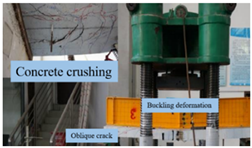 |
| Wang et al. [55] | 0.5 | 45 | 0 | The loading method of each stage is hierarchical, and the corresponding loading size of each stage is selected according to the observation requirements. | The failure stage of the test beam can be divided into the elastic stage, shaping stage, and failure stage. |  |
| Liu et al. [34] | 0.5 | 42 | 0.5 | In the elastic stage, the force-controlled loading technique is used to increase the load by 10 kN per layer. After the transition to the elastoplastic stage, the load increment of each layer is increased by 50 kN. | The deflection at the middle point of the steel box girder increases the fastest, and the bottom plate and web plate of the steel box girder produce buckling deformation. |  |
| Zhang et al. [56] | 1 | 58 | 0 | Force control | The load drops sharply after Vu, indicating brittle failure of the tested beam. During the whole loading process, the mid-span top concrete of all the beams was not crushed. |  |
| Mo et al. [37] | 0.5 | 38.5 | 0 0.5 1 | Loading protocol | Comments |  |
| ID | Test Value of Shear Capacity | American Calculated Value | Ratio | European Calculation | Ratio | Chinese Calculated Value | Ratio |
|---|---|---|---|---|---|---|---|
| 1 [47] | 625 | 312 | 0.4992 | 308 | 0.4928 | 299 | 0.4784 |
| 600 | 312 | 0.52 | 308 | 0.513333 | 299 | 0.498333 | |
| 550 | 312 | 0.567273 | 308 | 0.56 | 299 | 0.543636 | |
| 650 | 312 | 0.48 | 308 | 0.473846 | 299 | 0.46 | |
| 700 | 312 | 0.445714 | 308 | 0.44 | 299 | 0.427143 | |
| 395 | 312 | 0.789873 | 308 | 0.779747 | 299 | 0.756962 | |
| 2 [48] | 315 | 312 | 0.990476 | 308 | 0.977778 | 299 | 0.949206 |
| 341 | 312 | 0.914956 | 308 | 0.903226 | 299 | 0.876833 | |
| 376 | 312 | 0.829787 | 308 | 0.819149 | 299 | 0.795213 | |
| 304 | 312 | 1.026316 | 308 | 1.013158 | 299 | 0.983553 | |
| 393 | 312 | 0.793893 | 308 | 0.783715 | 299 | 0.760814 | |
| 393 | 312 | 0.793893 | 308 | 0.783715 | 299 | 0.760814 | |
| 3 [54] | 557 | 312 | 0.560144 | 308 | 0.552962 | 299 | 0.536804 |
| 538.5 | 312 | 0.579387 | 308 | 0.571959 | 299 | 0.555246 | |
| 520 | 312 | 0.6 | 308 | 0.592308 | 299 | 0.575 | |
| 588.5 | 312 | 0.530161 | 308 | 0.523364 | 299 | 0.508071 | |
| 723.5 | 312 | 0.431237 | 308 | 0.425708 | 299 | 0.413269 | |
| 395 | 312 | 0.789873 | 308 | 0.779747 | 299 | 0.756962 | |
| Mean value | 0.674566 | 0.665918 | 0.646459 |
| Item | ① Conventional 85 m Main-Span Steel–Concrete Composite Beam | ② Kezhu High-Speed 85 m Main-Span Narrow Steel Box Girder | ③ Conventional 75 m Main-Span Steel–Concrete Composite Beam | ④ Kezhu High-Speed 75 m Main-Span Narrow Steel Box Girder | ②/① | ④/③ |
|---|---|---|---|---|---|---|
| Steel beam (kg/m2) | 457 | 397 | 411 | 339 | 0.869 | 0.825 |
| Steel beam + bridge panel steel (kg/m2) | 584 | 562 | 521 | 496 | 0.962 | 0.952 |
| coating (m2/m2) | 9.28 | 7.28 | 9.33 | 7.32 | 0.784 | 0.785 |
Disclaimer/Publisher’s Note: The statements, opinions and data contained in all publications are solely those of the individual author(s) and contributor(s) and not of MDPI and/or the editor(s). MDPI and/or the editor(s) disclaim responsibility for any injury to people or property resulting from any ideas, methods, instructions or products referred to in the content. |
© 2024 by the authors. Licensee MDPI, Basel, Switzerland. This article is an open access article distributed under the terms and conditions of the Creative Commons Attribution (CC BY) license (https://creativecommons.org/licenses/by/4.0/).
Share and Cite
Chen, Y.; Xu, J.; Yuan, P.; Wang, Q.; Cui, G.; Su, X. Research Progress on Shear Characteristics and Rapid Post-Disaster Construction of Narrow-Width Steel Box–UHPC Composite Beams. Buildings 2024, 14, 1930. https://doi.org/10.3390/buildings14071930
Chen Y, Xu J, Yuan P, Wang Q, Cui G, Su X. Research Progress on Shear Characteristics and Rapid Post-Disaster Construction of Narrow-Width Steel Box–UHPC Composite Beams. Buildings. 2024; 14(7):1930. https://doi.org/10.3390/buildings14071930
Chicago/Turabian StyleChen, Yunteng, Jiawei Xu, Peilong Yuan, Qiang Wang, Guanhua Cui, and Xulin Su. 2024. "Research Progress on Shear Characteristics and Rapid Post-Disaster Construction of Narrow-Width Steel Box–UHPC Composite Beams" Buildings 14, no. 7: 1930. https://doi.org/10.3390/buildings14071930
APA StyleChen, Y., Xu, J., Yuan, P., Wang, Q., Cui, G., & Su, X. (2024). Research Progress on Shear Characteristics and Rapid Post-Disaster Construction of Narrow-Width Steel Box–UHPC Composite Beams. Buildings, 14(7), 1930. https://doi.org/10.3390/buildings14071930