Article

Temperature Effect of Composite Girders with Corrugated Steel Webs Considering Local Longitudinal Stiffness of Webs

School of Civil Engineering, Lanzhou Jiaotong University, Lanzhou 730070, China
*
Author to whom correspondence should be addressed.
Buildings 2024, 14(7), 1939; https://doi.org/10.3390/buildings14071939
Submission received: 8 May 2024 / Revised: 3 June 2024 / Accepted: 12 June 2024 / Published: 26 June 2024
(This article belongs to the Section Building Structures)

Abstract

:
The theoretical calculation formula for the temperature effect of composite box beams with corrugated steel webs and arbitrary temperature gradient distribution is derived based on the structural characteristics of such beams. This is achieved by considering the deformation coordination condition of the steel and concrete interface, as well as taking into account the longitudinal constraint effect of the web. An analysis is conducted to compare the results obtained from a fine finite element numerical example with those from the theoretical formula. This study also investigates the height of the common flexural zone of corrugated steel web and concrete, confirming the correctness of the theoretical formula. The findings indicate that, when 10% of the height of the corrugated steel web is considered as the common flexural area, there is optimal agreement between the theoretical values and finite element values, resulting in calculated results that are more consistent with actual stress states in this type of box girder bridge. Furthermore, it is observed that the interfacial shear force and interface slip between the steel and concrete in composite beams are not uniformly distributed along their longitudinal axis. Specifically, the interfacial shear force follows a hyperbolic cosine function along this axis, reaching its maximum value at mid-span while being zero at both ends. On the other hand, the interface slip follows a hyperbolic sine function along this axis, reaching its maximum value at the beam end while being zero within the span. It should be noted that factors such as the interface slip stiffness, temperature difference, and linear expansion coefficient have a significant influence on the temperature effects in composite beams. In addition to these factors, a reasonable arrangement of shear nails on steel plates has been identified as an effective method for mitigating adverse effects.

1. Introduction

The steel-mixed composite structure with a corrugated steel web offers clear force transmission, high prestressing efficiency, and the full utilization of material properties [1]. It has been widely adopted in bridge structures and high-rise buildings [2,3]. Bridge structures are directly exposed to the natural environment and are inevitably affected by temperature fluctuations. Concrete and steel possess similar coefficients of linear expansion, enabling composite beams to function harmoniously under overall uniform temperatures. However, due to the significantly higher thermal conductivity of steel compared to concrete (approximately 50 times greater), bridge structures experience increased temperature-induced stress under ambient conditions. This discrepancy becomes a primary factor influencing the design and calculation of bridges [4], as evidenced by instances of bridge collapses in Europe attributed to excessive temperature stress [5]. Moreover, owing to the poor thermal conductivity of concrete, the vertical temperature gradient within bridge structures exhibits a nonlinear distribution when exposed to sunlight. This results in significant shear forces at the interfaces of the composite beams and consequently generates secondary temperature-induced internal forces in statically indeterminate bridge structures [6].
Numerous scholars have extensively researched the calculation methods for temperature-induced stress in traditional steel–concrete composite beams, yielding significant findings. Chen et al. [7] derived calculation formulas for the interface shear force and relative slip of traditional steel–concrete composite beams under linear temperature action, considering the coordination of deformation between the concrete and steel beams. Zhou et al. [8] developed temperature stress calculation formulas for traditional steel–concrete composite beam bridges based on identical curvature and deformation coordination conditions between the concrete and steel beams, without considering the interface slip. Meanwhile, under conditions involving interface slip, Zhou et al. [9] deduced calculation methods for the interface shear, relative slip, and temperature stress of traditional steel–concrete composite beam bridges. Additionally, Liu et al. [10] derived analytical expressions for the interface shear force, relative slip, and temperature stress of traditional steel–concrete composite beam bridges with or without interface slip under any temperature gradient action.
The research on the temperature effect of composite box girders with corrugated steel webs primarily focuses on observing the temperature field of bridges, followed by numerical simulation using the finite element method. Qiang et al. [11] fitted measured data, which provide significant reference value for designing and calculating local bridges. Dong et al. [12] observed the sunshine temperature field of a long-span continuous box girder bridge with corrugated steel webs over a period of 3 days and analyzed the bridge’s temperature effect using finite element software in conjunction with measured data. Xu et al. [13] conducted a 9-month measurement of temperatures on a box girder bridge with corrugated steel webs, established a finite element model, and compared and analyzed the results from numerical simulations to real bridge temperature tests. Zhao et al. [14] studied the distribution law of sunlight temperature fields by observing the temperatures on a continuous box girder bridge with corrugated steel webs. Wang et al. [15] conducted on-site measurements of the temperature field for a new type of corrugated steel web bridge and used finite element software to comparatively analyze its temperature effect under both measured and standard temperatures.
At present, there is a lack of theoretical analysis on the interface mechanical behavior of corrugated steel web box girders under temperature effects. The unique structural form of corrugated steel web presents challenges in theoretical analysis. Existing specifications [16] mention that the longitudinal stiffness of the corrugated steel web can be neglected when subjected to axial force, but there is no clear provision regarding its longitudinal stiffness in temperature stress calculations. As indicated in the literature [17,18], it is inevitable that the upper region of the web will be constrained by the concrete bridge panel. Therefore, theoretical calculations for temperature effects should consider this constraint.
In this paper, we present a theoretical calculation method for analyzing the temperature effects on corrugated steel web composite box girders under arbitrary temperature gradients. This method accounts for the geometric characteristics of the corrugated steel web, as well as local constraints. The results aim to serve as a reference for the design calculations of such bridges.

2. Analysis of the Mechanical Properties of Corrugated Steel Web

According to the literature [2], the longitudinal apparent elastic modulus of corrugated steel web is very small, as shown in Equation (1). However, in a composite box girder with a corrugated steel web, the web is constrained by the concrete plate. This constraint should be considered when calculating the temperature effect of the composite beam.
E x = E s ( d 1 + d 2 ) 4 d 2 ( t h ) 2
where Ex is the apparent elastic modulus of the corrugated steel web; Es is the elastic modulus of the steel; t is the thickness of the corrugated steel web; h is the height of the corrugated steel web; and d1, d2, and d3 are the waveform parameters of the corrugated steel web, as shown in Figure 1b.
Figure 1a depicts the cross-section of the composite box girder with a corrugated steel web. A coordinate system xOy is established with the centroid of the section as the origin. In this system, tu and ts represent the thickness of the top and bottom plates of the composite beam, respectively, while hw denotes the height of the corrugated steel web. Additionally, a, b, and c refer to the widths of the top plate, cantilever plate, and bottom plate of the composite beam, respectively. h represents the longitudinal effective bending height of the corrugated steel web, taking into account the longitudinal constraints of concrete bridge panels. The calculation formula is presented in Equation (2).
h = δ h w
where δ represents the ratio of the effective bending height of the corrugated steel web to the height of the web.
Figure 2 presents a simplified diagram illustrating the temperature-induced force on the composite box girder, while considering the local constraint effect of the corrugated steel web. In the diagram, x1Ocy1 represents a local coordinate system with the centroid of the concrete slab as the origin, while x2Osy2 denotes a local coordinate system with the centroid of the corrugated steel web within the effective bending height range as the origin. The symbol q(x) refers to the shear stress at the interface of the composite beam. Nc and Ns represent the axial forces acting on the concrete slab and steel beam due to temperature, respectively. Similarly, Mc and Ms denote the bending moments experienced by the concrete slab and corrugated steel web due to temperature, respectively. yc and yc indicate the distances from Oc to both the upper and lower surfaces of the concrete, respectively. On the other hand, ys and ys represent the distances from Os to both the upper and lower sides of the corrugated steel web within its effective anti-bending range. Additionally, yco is defined as the distance between centroid Oc and centroid O, whereas yso is described as the distance between centroid Os and centroid O.

3. Effect of Temperature on Composite Box Girder with Corrugated Steel Web

3.1. Basic Assumption

(1)
Composite box girders with corrugated steel webs are assumed to have a quasi-flat section,
(2)
the composite box girder with a corrugated steel web is in an elastic working state,
(3)
the friction between the corrugated steel web and concrete plate interface is not considered. The shear force of the shear nails is directly proportional to the relative slip between the layers,
(4)
the shear keys are responsible for bearing all the horizontal shear forces at the interface of the composite box girder with corrugated steel webs, and they vary directly with the interlayer slip,
(5)
at the interface of the corrugated steel web composite box girder, there is no longitudinal lifting, and the curvature of the steel beam matches that of the concrete slab.

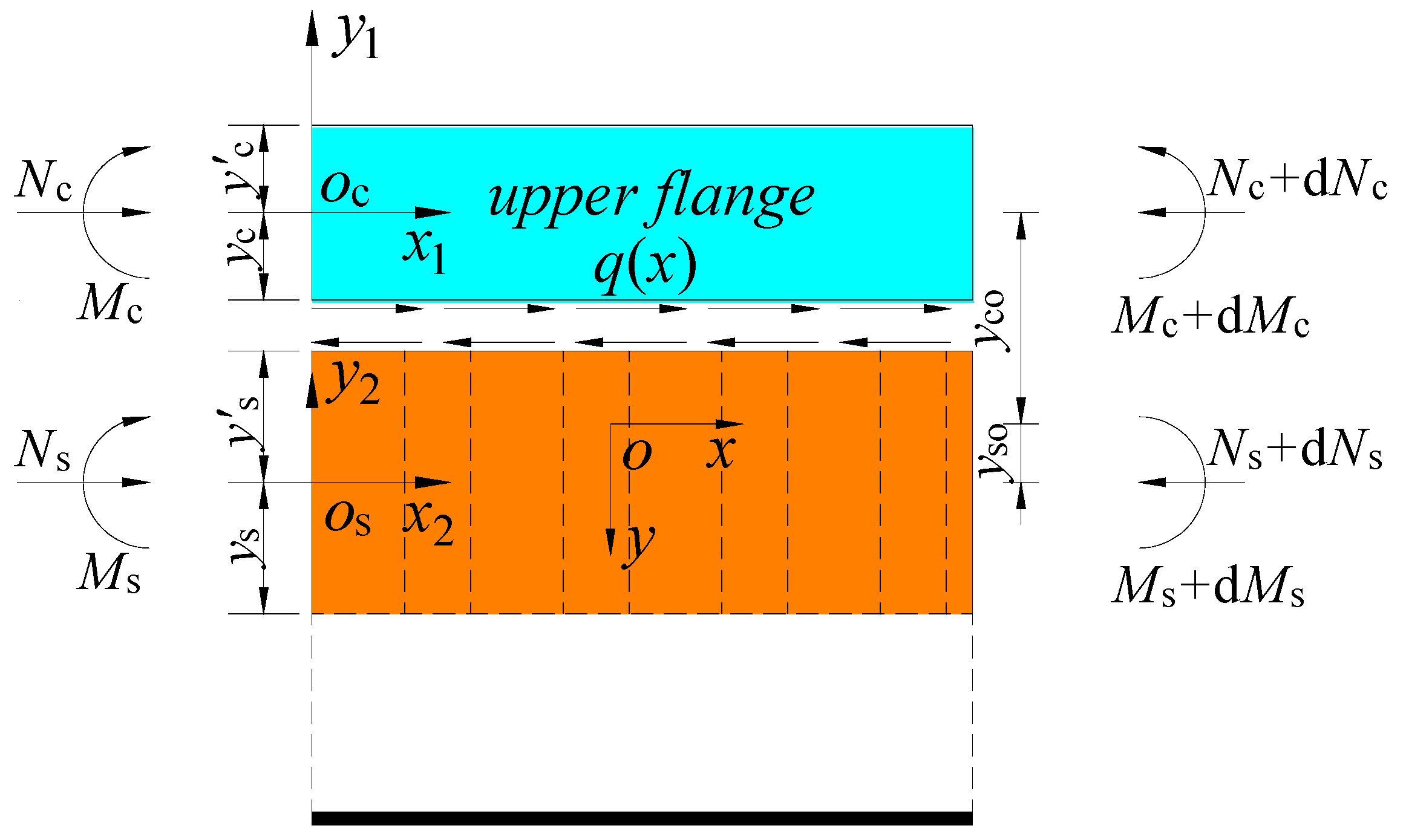
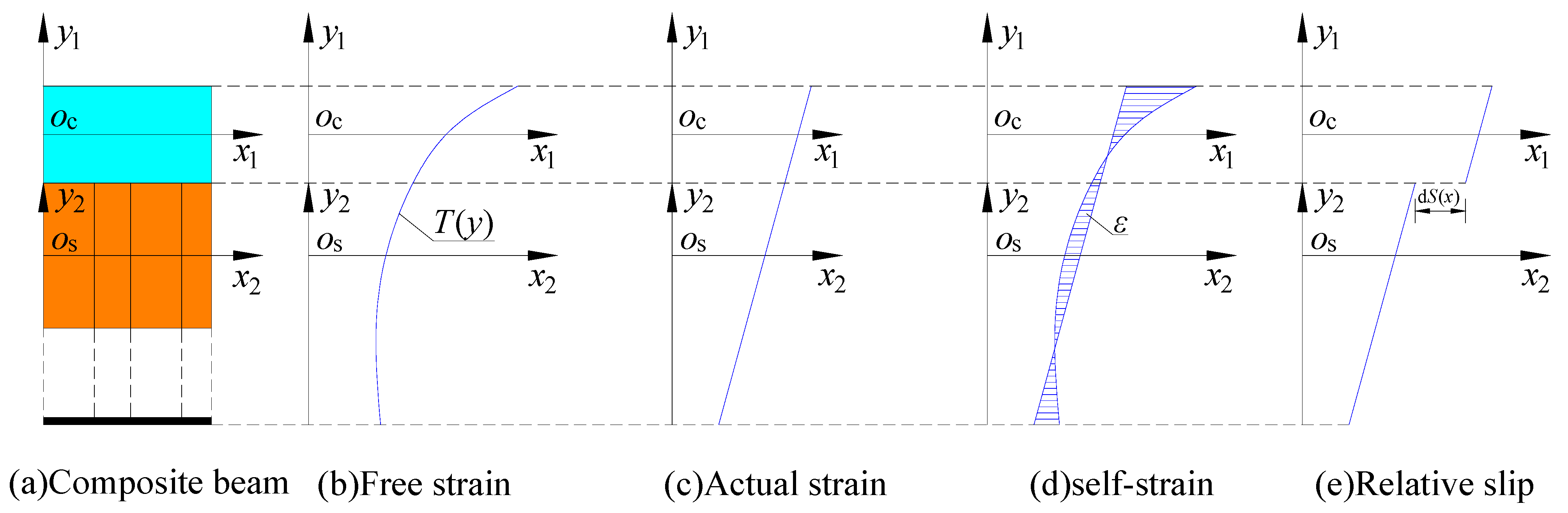
3.2. Analysis of Temperature Effects

Figure 3 depicts the strain diagram of the composite beam under a temperature gradient.
In the diagram, T(y) represents the vertical temperature change curve of the composite beam at any given section; ε denotes the self-strain of the composite beam section; and dS(x) indicates the relative slip deformation of the composite beam. The remaining elements follow the principles stated earlier.
In the presence of a temperature gradient, the longitudinal fibers of the corrugated steel web composite box girder are allowed to stretch freely. The resulting strain along the beam height direction is illustrated in Figure 3b. It is essential for the cross-section of the composite beam to maintain the assumption of a pseudo-flat section, as depicted in Figure 3c. This results in the formation of self-strain, as shown in Figure 3d, and subsequently generates self-confining stress.
σ = E ε + φ y α T ( y )
where α is the linear expansion coefficient and φ is the curvature of the composite beam under the action of temperature.
It is observed that the self-imposed stress on the concrete slab and corrugated steel web, induced by temperature gradients, can be expressed as follows:
σ c ( y 1 ) = E c ε co + φ y 1 α c T ( y 1 )
σ s ( y 2 ) = E s ε so + φ y 2 α s T ( y 2 )
where Ec and Es represent the elastic modulus of the concrete and steel, respectively. αc and αs denote the linear expansion coefficients of the concrete and steel, respectively. εco and εso indicate the strain at the centroid of the concrete slab and the strain at the centroid of the corrugated steel web within the effective stiffness range, respectively.
The axial force and bending moment induced by the temperature gradients in the concrete slabs and corrugated steel webs can be expressed as follows:
N c = A c E c ε co + φ y 1 α c T c ( y 1 ) d A c = ε co E c A c E c α c T 1
N s = A 0 E s ε so + φ y 2 α s T s ( y 2 ) d A s = ε so E s A s E s α s T 2
M c = A c E c ε co + φ y 1 α c T c ( y 1 ) y 1 d A c = φ E c I c α c E c T 3
M s = A s E s ε so + φ y 2 α s T s ( y 2 ) y 2 d A s = φ E s I s α s E s T 4
where Ac and As represent the cross-sectional areas of the concrete bridge panels and corrugated steel webs, respectively, within the effective stiffness range. T1, T2, T3, and T4 are coefficients associated with the temperature gradient distribution mode, as expressed below:
T 1 = A c T c ( y 1 ) d A c
T 2 = A 0 T s ( y 2 ) d A s
T 3 = A c T c ( y 1 ) y 1 d A c
T 4 = A s T s ( y 2 ) y 2 d A s
Considering the axial force balance at the interface between the concrete slab and the steel beam with a corrugated steel web, it is evident that:
N c = N s = Q ( x )
Substituting Equation (14) into Equation (6), and then solving for Equation (7), results in:
ε co = Q ( x ) E c A c + α c T 1 A c
ε so = Q ( x ) E s A s + α s T 2 A s
It can be inferred that the total moment of the composite beam around the section mandrel, under the influence of temperature, equals 0:
N c y c N s y s + M c + M s = 0
Substituting Equations (8) and (9) into Equation (17) shows:
φ = α c E c T 3 + α s E s T 4 ( y co + y so ) Q ( x ) E c I c + E s I s
The relative slip deformation between the concrete slab and the corrugated steel web is denoted as dS(x), as illustrated in Figure 3. This represents the relationship between the relative slip deformation and relative slip strain.
d S ( x ) = ε co ε so φ ( y co + y so )
According to Equation (4), the relationship between the slip and shear stress at the interface of the concrete slab and corrugated steel web is as follows:
q ( x ) B d ( x ) = k S ( x ) d ( x )
where B represents the width of the contact surface and k denotes the equivalent shear-slip stiffness of the shear bond.
The relationship between the mechanical shear force and shear stress of materials can be established.
Q ( x ) = q ( x ) B
The derivation of Equation (21) to Equation (20) is accomplished by taking the derivative of both sides.
Q ( x ) = k d S ( x )
Equations (15), (16) and (22) can be inserted into Equation (19):
Q ( x ) r 2 Q ( x ) = θ
where r and θ represent the parameters in Equation (23):
r 2 = k ( 1 E c A c + 1 E s A s + ( y co + y so ) 2 E c I c + E s I s )
θ = k ( α c T 1 A c α s T 2 A s ( y co + y so ) α c E c T 3 + α s E s T 4 E c I c + E s I s )
Equation (23) represents a second-order differential equation with constant coefficients, and its general solution can be expressed as follows:
Q ( x ) = C 1 e r x + C 2 e r x θ r 2
where C1 and C2 represent the undetermined coefficients.
Considering the slip relationship between a concrete slab and corrugated steel web, the following boundary conditions are proposed for a simply supported beam with a span of l (see Figure 4).
At the midspan x = 0, the relative slip is 0 and its shear stress is also 0:
Q ( x )   x = 0 = 0
At the beam end x = l/2, the axial force of the concrete bridge panel is 0. This indicates that:
Q ( x )   x = ± l / 2 = 0
Equations (27) and (28) can be simultaneously derived by substituting Equation (26):
C 1 = C 2 = θ r 2 ( e r l / 2 + e r l / 2 )
By substituting the undetermined coefficients C1 and C2 into Equation (26), the interfacial shear force can be determined:
Q ( x ) = θ r 2 cosh ( r x ) cosh ( r l / 2 ) 1
The interfacial shear stress can be determined by deriving Equation (30):
q ( x ) = θ r B sinh ( r x ) cosh ( r l / 2 )
Substituting Equation (31) into Equation (20) allows for the determination of the relative slip in a composite box girder with a corrugated steel web:
S ( x ) = θ k r sinh ( r x ) cosh ( r l / 2 )
After substituting Equation (30) into Equations (15), (16) and (18), we can determine the stress σcu and σcd at the upper and lower edges of the concrete slab.
σ cu = E c ( ε co + φ y c α c T cu )
σ cd = E c ( ε co + φ y c α c T cd )
Equations (30)–(32) demonstrate that the interfacial shear force in a composite box girder with corrugated steel webs, considering the relative slip of the interface and influenced by temperature, follows a hyperbolic cosine function distribution along the beam length. Similarly, the interfacial shear stress and relative slip adhere to a hyperbolic sine function distribution along the beam length.

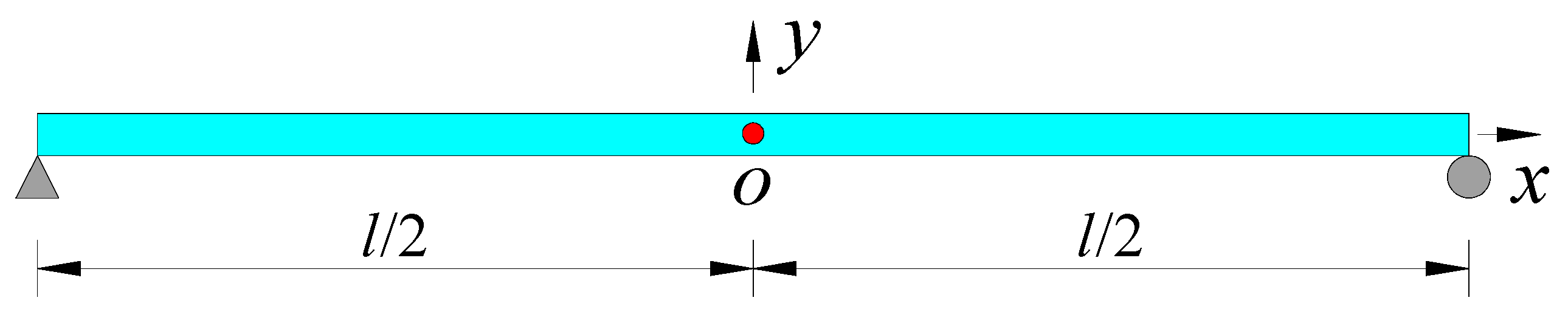
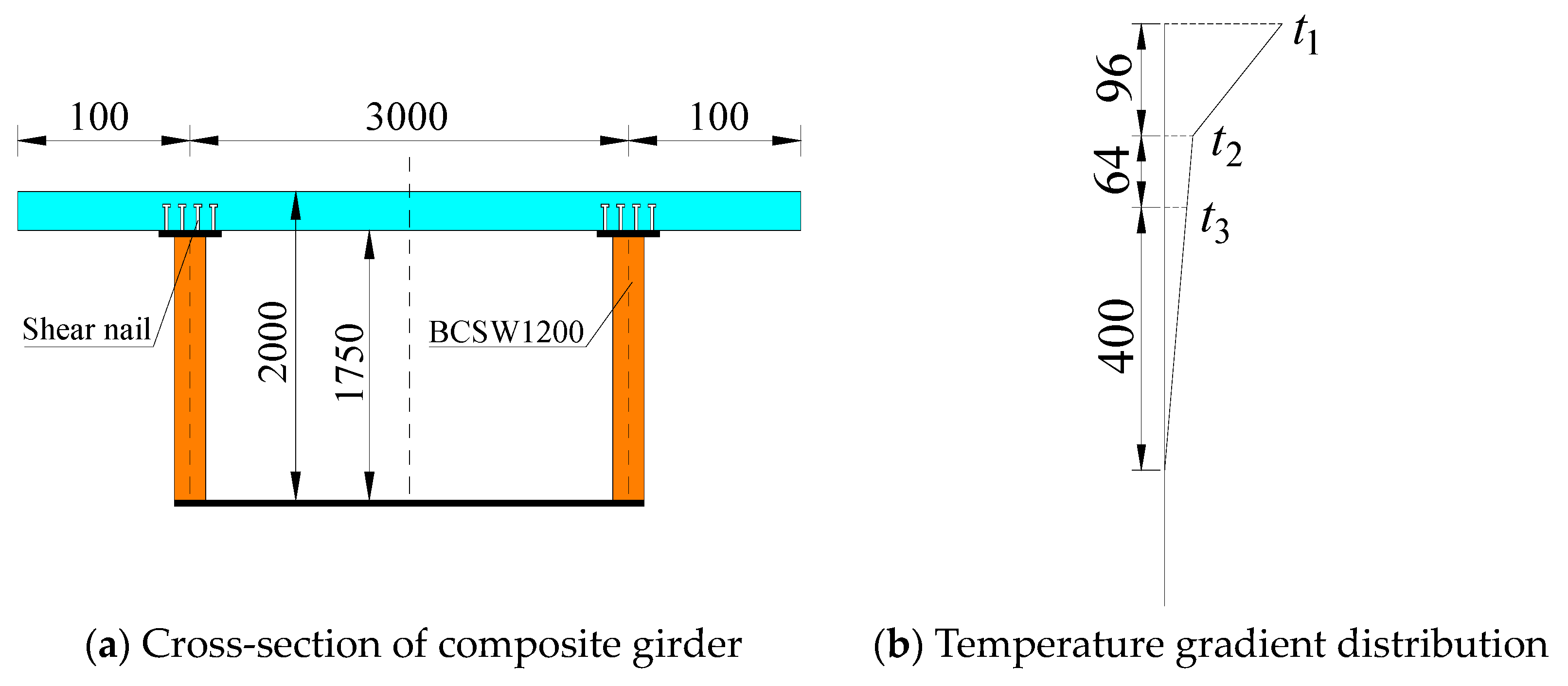
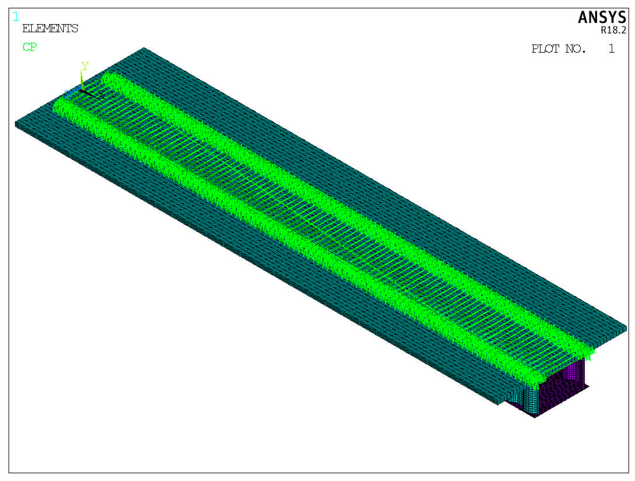
4. Numerical Example

Using the real bridge case study from the literature [19], we employed the derived calculation formula and ANSYS 18.2 finite element method to calculate and analyze the temperature effect of a composite box girder with a corrugated steel web.
The cross-section of the composite beam is depicted in Figure 5a. The concrete slab is constructed with C55, featuring a thickness of 0.25 m, an elastic modulus of 3.55 × 10⁴ MPa, and a linear expansion coefficient of 1.0 × 10⁵. The corrugated steel web and steel bottom plate are fabricated from Q345 steel, with elastic moduli of 2.1 × 10⁵ MPa and linear expansion coefficients of 1.2 × 10⁵, respectively.
Along the small flange of the upper part of the corrugated steel web, four rows of shear studs are installed longitudinally at a transverse interval of 0.1 m. As per reference [20], the shear slip stiffness per meter extension is calculated as 4.971 × 10³ MPa.
Please refer to Figure 5b for the temperature gradient mode specified in the British specification BS5400 [21], where t1 = 10 °C; t2 = 4.0 °C; and t3 = 3.5 °C.
The finite element software ANSYS was used to construct the aforementioned model. The upper concrete slab was simulated using the solid65 solid unit, while the corrugated steel web was modeled using the shell181 shell unit. Additionally, the shear nails were represented by the combin39 spring unit. The finite element model is illustrated in Figure 6.

5. Comparative Analysis of Calculation Results

5.1. Determination of the Standard Resistance to Bending

Equations (30) and (32) demonstrate a hyperbolic function distribution of the interlayer slip and interlayer shear within composite box beams featuring corrugated steel webs. Specifically, the calculation focuses on the end and span of the composite beams, with δ incrementally increasing from 0 to 0.20 in steps of 0.05. The resulting interface slip at the end of composite beams and interface shear at the span are detailed in Table 1 and depicted in Figure 7 and Figure 8.
It is clear from Table 1 and Figure 7 and Figure 8 that the height of the common flexural zone has a significant impact on the interface slip and shear of the composite box girder with corrugated steel webs. When δ = 0.1, meaning that 10% of the corrugated steel web is treated as the common bending area, the results obtained from this method are well-aligned with those derived from the finite element analysis.
The theoretical calculations presented in this paper closely match the finite element analysis results, as depicted in Figure 7 and Figure 8. The distribution patterns of the interface slip and shear along the composite beam are illustrated: the interface slip follows a hyperbolic sine function distribution, while the interface shear follows a hyperbolic function distribution. At the beam ends (x = ±l), the interface slip reaches its maximum value, whereas it remains at 0 in the middle span. Conversely, interface shear peaks at the middle span (x = l/2) and is 0 at the beam ends. When δ = 0.1, there is a 3.52% difference between the theoretical and finite element values for the interface slip and a 4.84% difference for the interface shear at the middle span.

5.2. Investigation of Influencing Factors

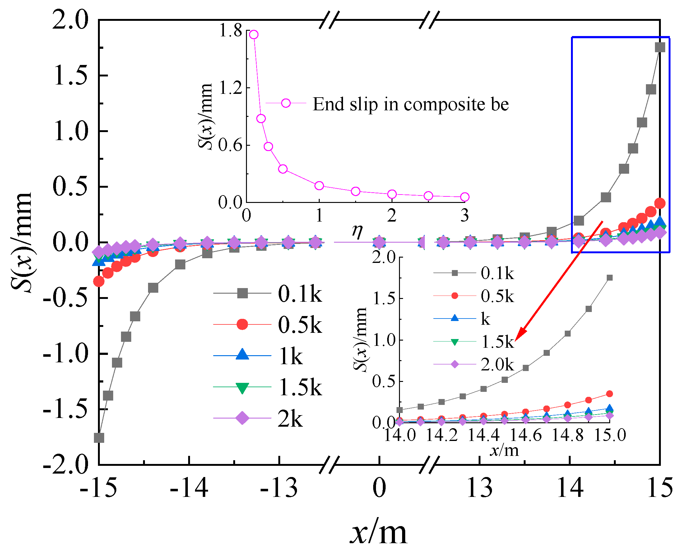
5.2.1. Analysis of Glide Stiffness

The interface slip stiffness (k) plays a crucial role in determining the longitudinal cooperative force of the composite beam. As indicated by Equation (30), the interlayer slip stiffness does not affect the interface shear force of the composite beam. To investigate the impact of the interface slip stiffness on the interface slip of composite beams, we selected δ = 0.1 and varied the longitudinal slip stiffness to be 0.1 k, 0.5 k, 1 k, 1.5 k, and 2 k, respectively. The results for the interface slip of composite beams are presented in Figure 9. It is evident that there is a negative correlation between the interface slip and slip stiffness: as the interface slip stiffness increases, the interlayer slip decreases, indicating a closer bond between the concrete slab and steel beam with corrugated steel webs.

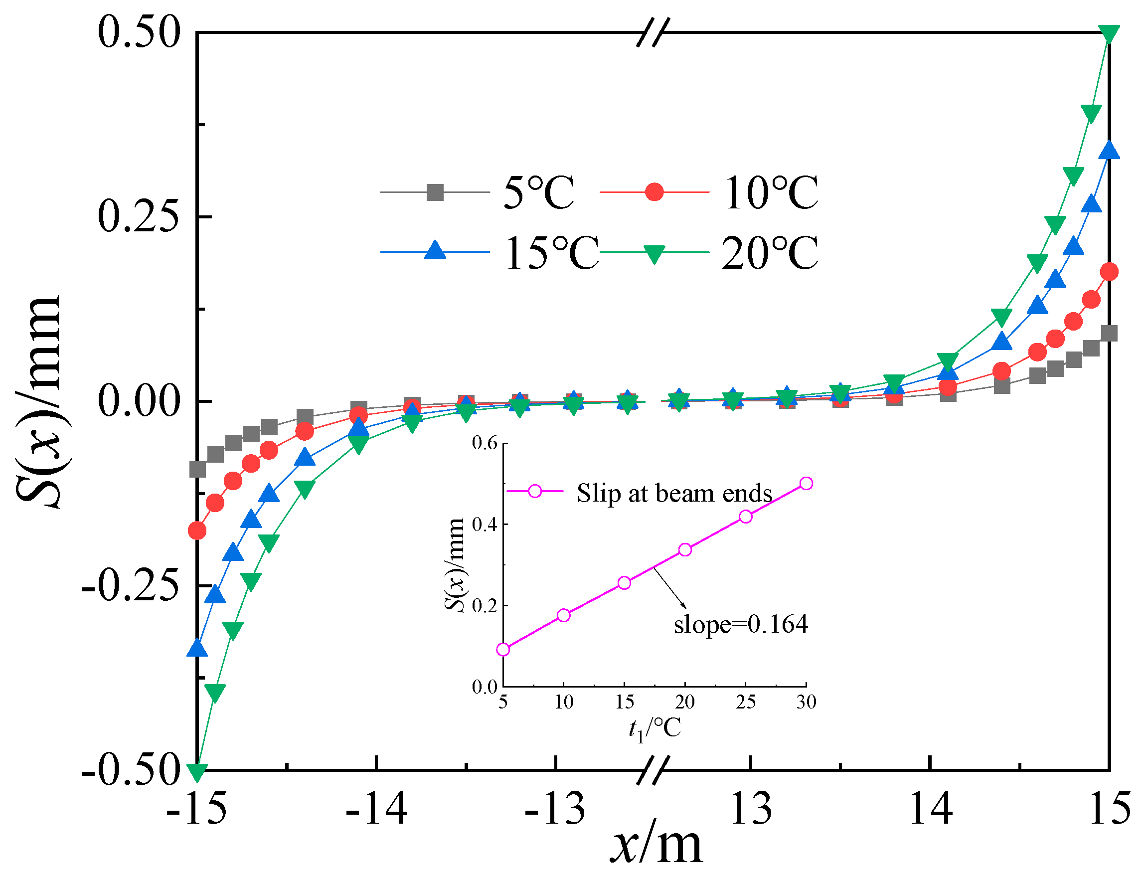
5.2.2. Analysis of Temperature Differences

To examine the influence of temperature variation on the interfacial slip and shear force of the composite beam’s concrete slab, a value of δ = 0.1 is selected. The temperature (t3) at the top of the concrete bridge panel is varied between 5 °C, 10 °C, 15 °C, and 20 °C, and the corresponding interfacial slip and shear force are calculated accordingly, as illustrated in Figure 10 and Figure 11.
It is apparent from Figure 10 and Figure 11 that the distribution patterns of the interface slip and interface shear force along the longitudinal beam of the composite beam remain consistent with the variation in the concrete slab temperature (t3). There exists a positive linear correlation between the slip at the beam end and the temperature difference, indicating an increase in the interlayer slip with higher temperature differences. Similarly, there is a positive linear relationship between the mid-span shear force and temperature difference, which also increases with higher temperature differences. The rationality of Equations (30) and (32) is once again proven. It is worth noting, as highlighted in the literature [4], that China’s vast territory leads to significant variations in vertical temperature gradient models across different regions. Therefore, selecting an appropriate temperature gradient model can help to mitigate calculation deviations arising from temperature effects.

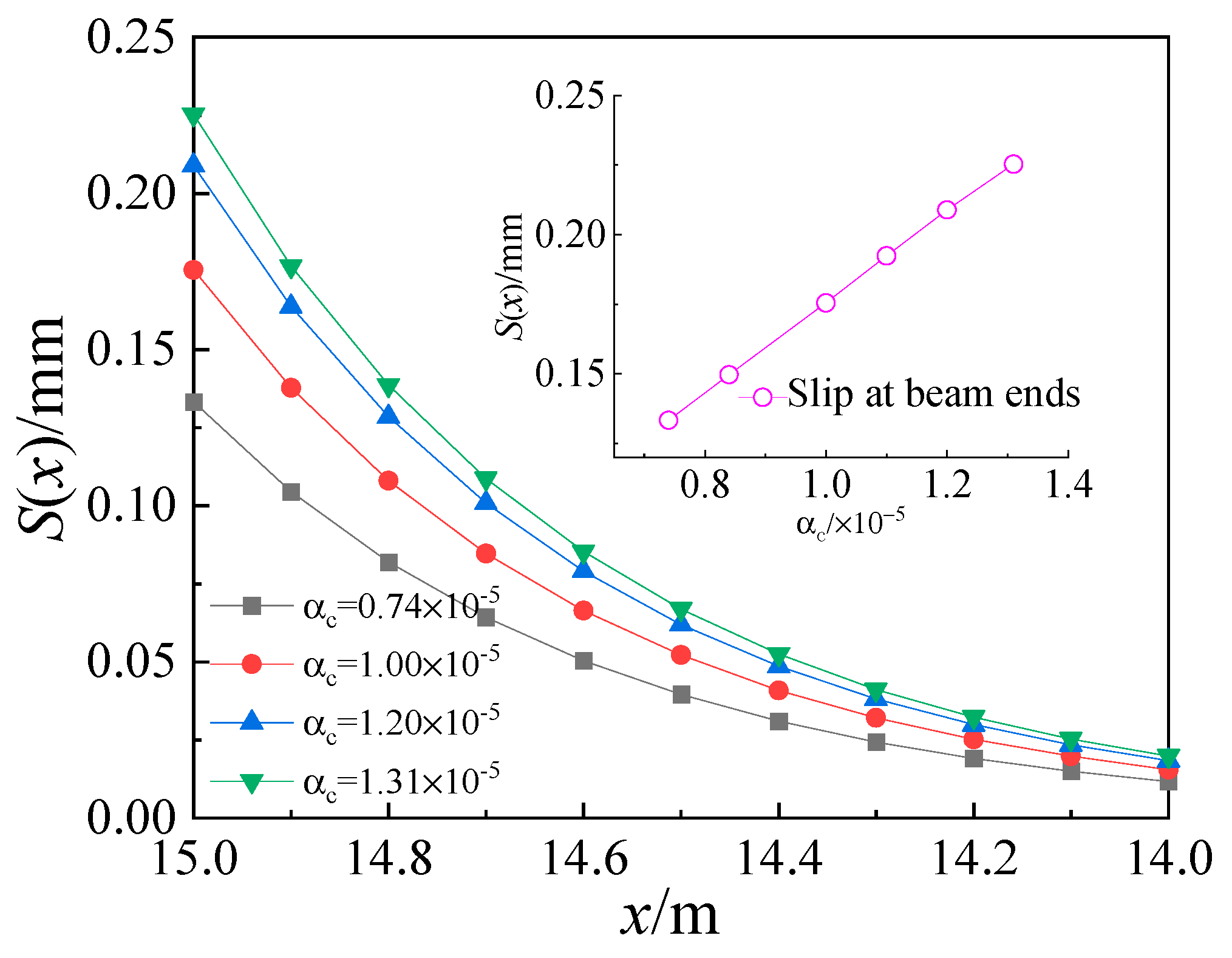
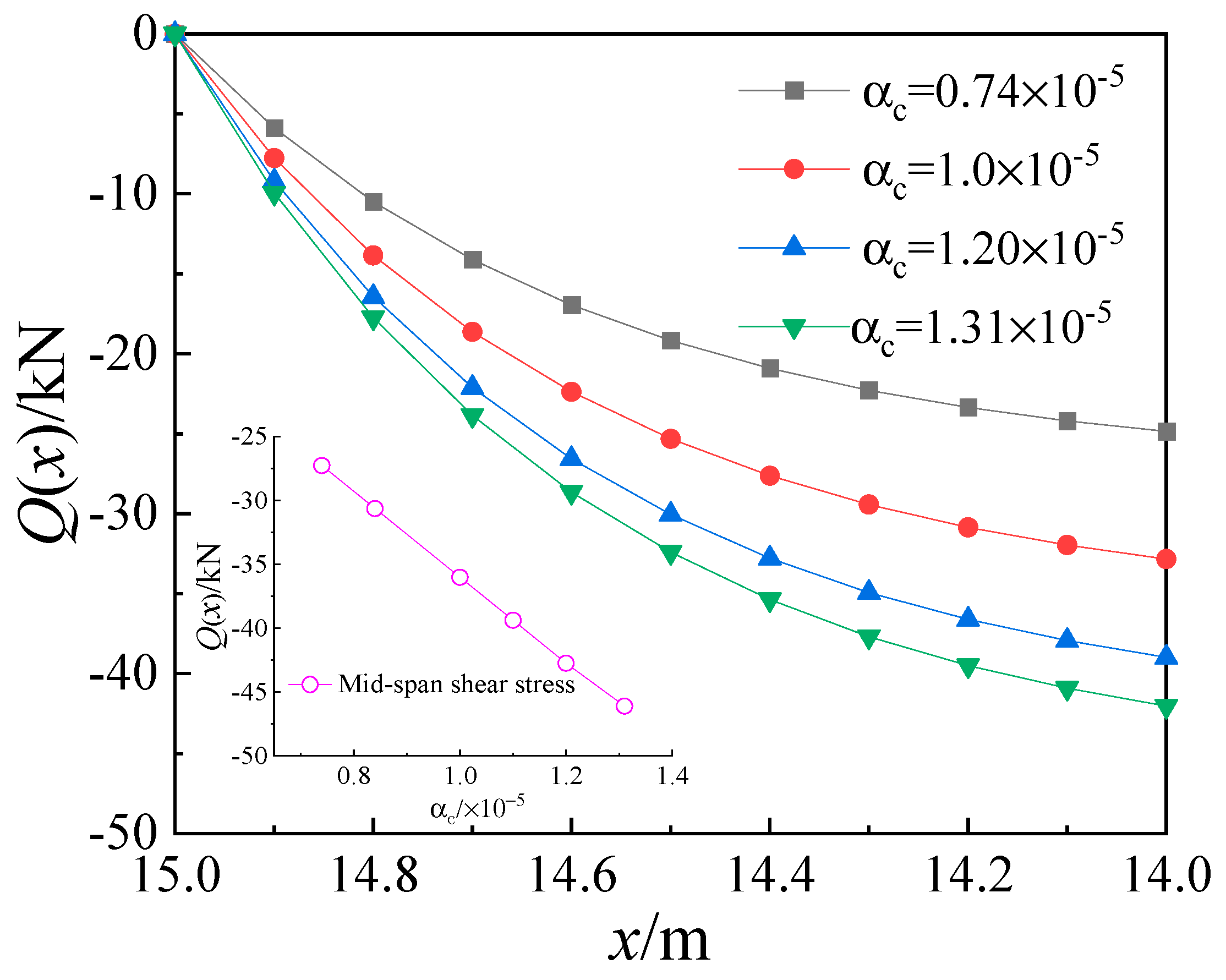
5.2.3. Analysis of the Linear Expansion Coefficient of Concrete

Concrete, being a composite material, exhibits a linear expansion coefficient influenced by factors such as aggregate type and temperature. According to the literature [22], the linear expansion coefficient (αc) of concrete typically ranges from 0.74 × 10⁻⁵ to 1.31 × 10⁻⁵. To assess the impact of concrete’s linear expansion coefficient on temperature, we selected a δ value of 0.1 and considered αc values of 0.74 × 10⁻⁵, 1.00 × 10⁻⁵, 1.20 × 10⁻⁵, and 1.31 × 10⁻⁵, respectively. Subsequently, we calculated the interface slip and interface shear of composite beams based on these values. The calculation results are presented in Figure 12 and Figure 13.
It is evident from Figure 12 and Figure 13 that there exists a positive linear correlation between the linear expansion coefficient of concrete and both the interface slip and interface shear. As the vertical temperature distribution mode remains consistent, both the interface slip and shear force increase in tandem with the linear expansion coefficient. Even when αc = 1.20 × 10⁻⁵, which equals αs, the composite beams still demonstrate significant levels of interface slip and shear force due to the vertical temperature distribution mode.

6. Conclusions

(1)
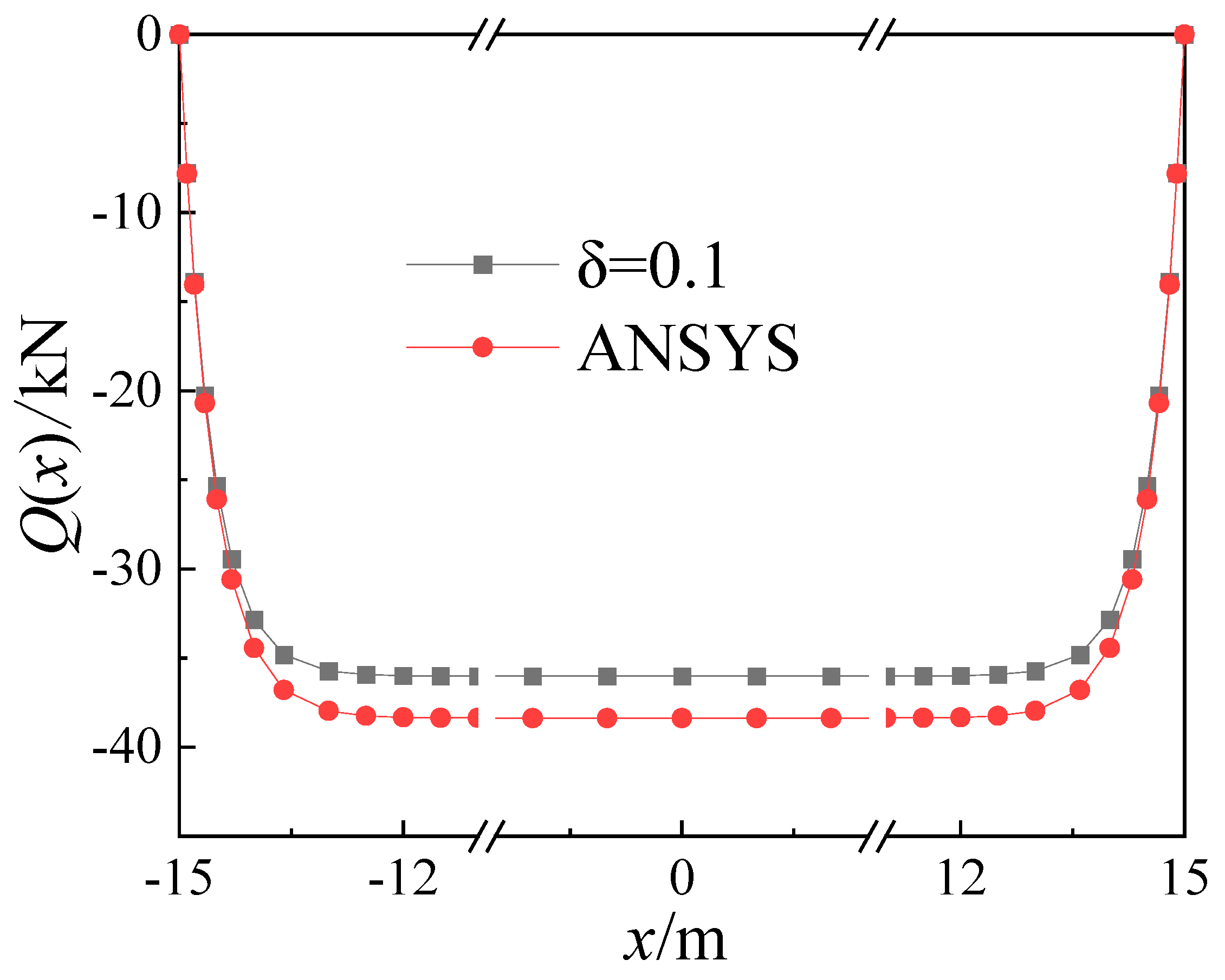
Taking into consideration the influence of the local longitudinal stiffness of the web, the calculation method for determining the temperature effect on composite box girders with corrugated steel webs under various temperature gradient modes aligns excellently with the results obtained from the ANSYS finite element analysis. This validates the accuracy of the theoretical derivation.
(2)
Considering 10% of the height of the corrugated steel web as the common bending zone improves the accuracy of the calculation results. Taking into account the longitudinal constraints of the web enhances the consistency between the theoretical calculations and the actual stress conditions observed in such bridges.
(3)
The distribution of the interfacial shear force and interfacial slip in the composite box girder with corrugated steel webs varies along the longitudinal beam. The highest relative slip occurs at the end of the composite beam, while it is negligible in the middle span. Similarly, the interface shear force is minimal at the beam ends and reaches its maximum value at the mid-span. Therefore, it is advisable to arrange the shear nails segmentally along the length of the composite box girder and reinforce them at the ends.
(4)
The accuracy of temperature effect calculations for corrugated steel web composite box girders is influenced by factors such as longitudinal sliding stiffness, temperature difference, and concrete linear expansion coefficient. When computing the temperature effect for such bridges, it is crucial to reasonably select a vertical temperature distribution model, account for the variability of the concrete linear expansion coefficient, and arrange the shear nails in a rational manner.

Author Contributions

Conceptualization, M.C.; Formal analysis, M.C.; Investigation, M.C. and F.W.; Data curation, M.C.; Writing—original draft, M.C.; Writing—review & editing, S.L. and F.W.; Supervision, S.L. All authors have read and agreed to the published version of the manuscript.

Funding

This work described in this paper was supported partially by two grants from the National Natural Science Foundation of China (Grant No. 51868040 and Grant No. 52268027).

Data Availability Statement

The original contributions presented in the study are included in the article, further inquiries can be directed to the corresponding author.

Conflicts of Interest

The authors declare that they have no known competing financial interests or personal relationships that could have appeared to influence the work reported in this paper.

References

  1. Elgaal, Y.M. Shear strength of beans with corrugated web. J. Struct. Eng. 1996, 122, 90. [Google Scholar]
  2. Li, H.J.; Ye, J.S.; Wan, S.; Wu, W. Influence of shear Deformation on Deflection of Box Girder with Corrugated Steel Webs. J. Traffic Transp. Eng. 2002, 4, 17–20. (In Chinese) [Google Scholar]
  3. Zhou, X.F.; Wang, Z.Y.; Liu, Z.F.; Liu, Y.; Jiang, Y.; Gai, W. Study on strength and stress properties of external prestressed composite beams with corrugated steel webs. J. Build. Struct. 2021, 42, 229–238. (In Chinese) [Google Scholar]
  4. Liu, Y.J.; Liu, J. Review on temperature action and effect of steel-concrete composite girder bridge. J. Traffic Transp. Eng. 2020, 20, 42–59. (In Chinese) [Google Scholar]
  5. Heckel, R. The Fourth Danube Bridge in Vienna-damage and repair. Dev. Bridge Des. Constr. Process 1971, 588–598. [Google Scholar]
  6. Dilger, W.H.; Ghali, A.; Chan, M.; Cheung, M.S.; Maes, M.A. Temperature stresses in composite box girder bridges. J. Struct. Eng. 1983, 109, 1460–1478. [Google Scholar] [CrossRef]
  7. Chen, Y.J.; Ye, M.X. Analyses of responses of composite girders under the action of temperature. China Railw. Sci. 2001, 22, 48–53. (In Chinese) [Google Scholar]
  8. Zhou, L.; Lu, Y.C.; Li, X.F. Calculation of temperature stress of steel-concrete composite beam. J. Highw. Transp. Res. Dev. 2012, 29, 83–88. (In Chinese) [Google Scholar]
  9. Zhou, Y.C.; Hu, S.N.; Song, L.; Li, Z. Effect analysis of steel-concrete composite beam caused by sudden change of temperature. J. Traffic Transp. Eng. 2013, 13, 20–26. (In Chinese) [Google Scholar]
  10. Liu, Y.J.; Liu, J.; Zhang, N.; Lei, X.U. Analytical solution of temperature effects of steel-concrete composite girder. J. Traffic Transp. Eng. 2017, 17, 9–19. (In Chinese) [Google Scholar]
  11. Qiang, J.T.; Yao, C.; Zhang, F. Study of temperature effect on the composed bridge with corrugated steel webs. Highway 2016, 61, 54–57. (In Chinese) [Google Scholar]
  12. Dong, X.; Deng, Z.Q.; Li, S.S.; Feng, Z. Research on sun light temperature field and thermal difference effect of long span box girder bridge with corrugated steel webs. Eng. Mech. 2017, 34, 230–238. (In Chinese) [Google Scholar]
  13. Xu, X.F.; Zhang, F.; Liu, J.Q. Temperature distribution of box girder with corrugated steel webs. J. Chongqing Jiaotong Univ. Nat. Sci. 2018, 37, 1–10. (In Chinese) [Google Scholar]
  14. Zhao, P.; Ye, J.S. Analysis of transverse temperature effects on the deck of box girder with corrugated steel webs. J. Harbin Eng. Univ. 2019, 40, 974–978. (In Chinese) [Google Scholar]
  15. Wang, L.; Liu, S.Z.; Ding, W.; Liu, S.; Wu, W. Analysis on temperature effect of new-pattern corrugated steel web composite box girder in dry cold region. Adv. Eng. Sci. 2021, 53, 60–66. (In Chinese) [Google Scholar]
  16. CJJ/T 272—2017; Technical Standard for Composite Girder Bridges with Corrugated Steel Webs. China Building Industry Press: Beijing, China, 2017. (In Chinese)
  17. Li, H.J. Experimental Study and Analysis on Torsion and Distortion Corrugated Steel Webs and Composite Deck; SouthEast University: Dhaka, Bangladesh, 2003. (In Chinese) [Google Scholar]
  18. Zhang, Y.H.; Sun, C.C. Analysis on the torsion effect of box girders with corrugated steel webs considering local longitudinal stiffness of webs. J. Southeast Univ. Nat. Sci. Ed. 2022, 54, 133–140. (In Chinese) [Google Scholar]
  19. Wang, L.; Liu, S.Z.; Li, Z.Q.; Huang, J.; Ding, W. Temperature Effect of Simply Supported Composite Box Girder with Corrugated Steel Webs and Composite Deck. Adv. Eng. Sci. 2021, 51, 195–201. (In Chinese) [Google Scholar]
  20. Huang, S.H.; Cai, C.Z.; Zou, Y.F.; He, X.H.; Zhou, T.; Zhu, X. Experimental and numerical investigation on the temperature distribution of composite box-girders with corrugated steel webs. Struct. Control Health Monit. 2022, 29, e3123. [Google Scholar] [CrossRef]
  21. BS5400; Steel, Concrete and Composite Bridges—Part 2. Specification for Loads. British Standards Institution: London, UK, 1978.
  22. Neville, A.M. Properties of Concrete; LAP: London, UK, 1995. [Google Scholar]
Figure 1. Cross-section of composite girders and waveform.
Buildings 14 01939 g001
Figure 2. Composite girder force diagram.
Buildings 14 01939 g002
Figure 3. Temperature stress distribution of composite girder.
Buildings 14 01939 g003
Figure 4. Coordinates of simply supported girder.
Buildings 14 01939 g004
Figure 5. Cross-section of composite girder and Temperature gradient distribution (unit: mm).
Buildings 14 01939 g005
Figure 6. ANSYS finite element model.
Buildings 14 01939 g006
Figure 7. Interface slip at different δ values.
Buildings 14 01939 g007
Figure 8. Shear distribution at the interface.
Buildings 14 01939 g008
Figure 9. Effect of k on interface slip.
Buildings 14 01939 g009
Figure 10. Influence of temperature difference on interface slip.
Buildings 14 01939 g010
Figure 11. Influence of temperature difference on interfacial shear.
Buildings 14 01939 g011
Figure 12. Influence of concrete linear expansion coefficient on interface slip.
Buildings 14 01939 g012
Figure 13. Influence of concrete linear expansion coefficient on interfacial shear.
Buildings 14 01939 g013
Table 1. Calculation results of temperature effect with different δ values.
δMid-Span Shear Force (Q(x)/kN)The Slipping of the Beam End S(x)/mm
0−31.4760.1570
0.05−33.3190.1676
0.10−36.0110.1755
0.15−57.0580.2406
0.20−71.4410.3075
ANSYS−37.8430.1819
Disclaimer/Publisher’s Note: The statements, opinions and data contained in all publications are solely those of the individual author(s) and contributor(s) and not of MDPI and/or the editor(s). MDPI and/or the editor(s) disclaim responsibility for any injury to people or property resulting from any ideas, methods, instructions or products referred to in the content.

