
Settlement Calculation of Semi-Rigid Pile Composite Foundation on Ultra-Soft Soil under Embankment Load
Abstract
:1. Introduction
2. Analytical Model
2.1. Basic Assumptions
- (1)
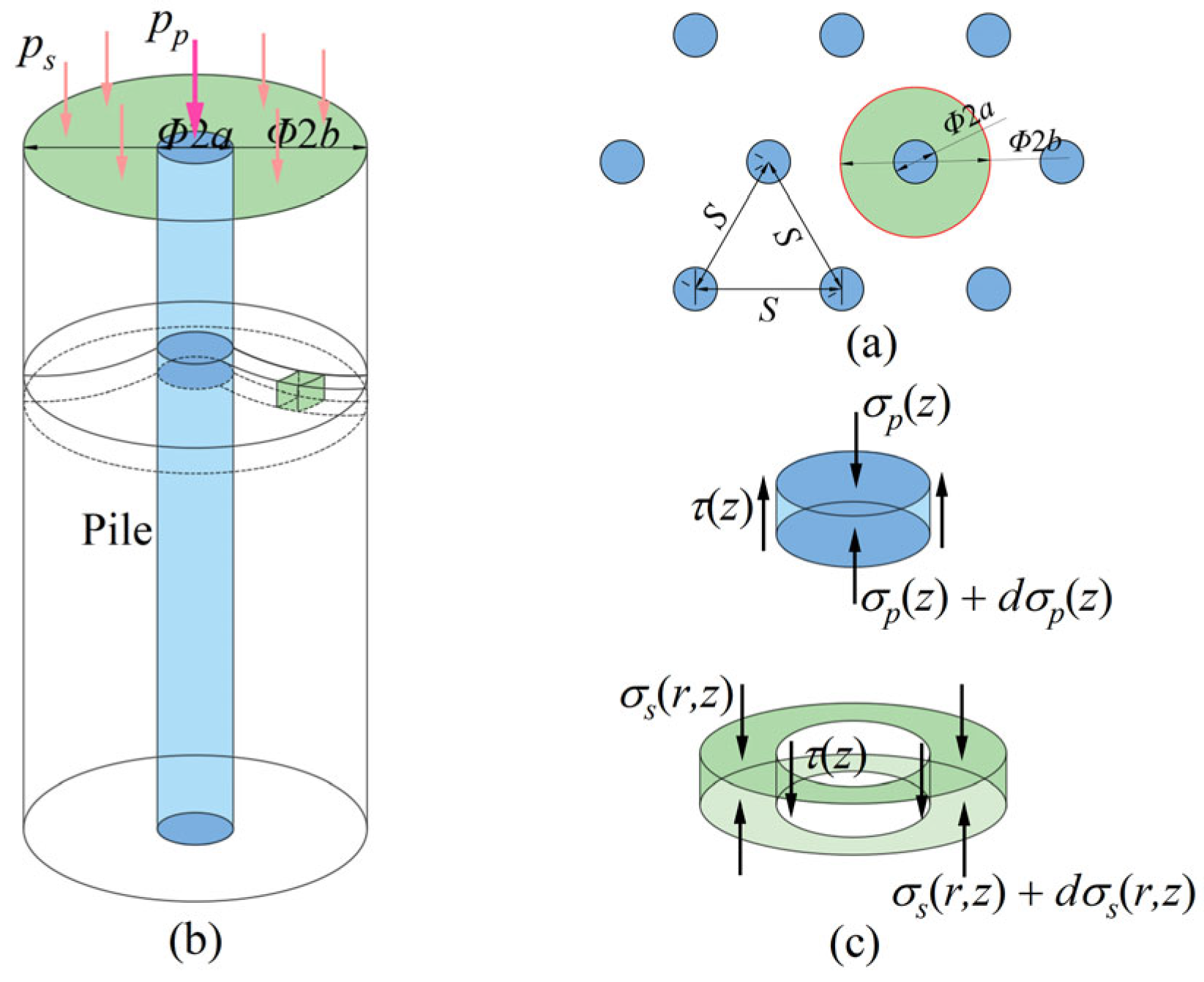
- The embankment filling is simplified as a uniform load p, and after the adjustment of the cushion layer, it acts on the top surface of the pile and the surrounding soil in the form of a uniform load pp and ps.
- (2)
- The pile and the surrounding soil are isotropic linear elastomers. The elastic modulus, Poisson’s ratio, and diameter of the pile are constant. The compression modulus and Poisson’s ratio of the surrounding soil are constant.
- (3)
- The pile stress distribution is uniform, and the settlement is the same in the same horizontal plane of composite foundation. The stress and settlement of the surrounding soil at the same horizontal plane are nonuniform. Only vertical deformation occurs in the pile and surrounding soil, and lateral deformation is negligible. Only one-dimensional uniform compression occurs in the underlying layer.
- (4)
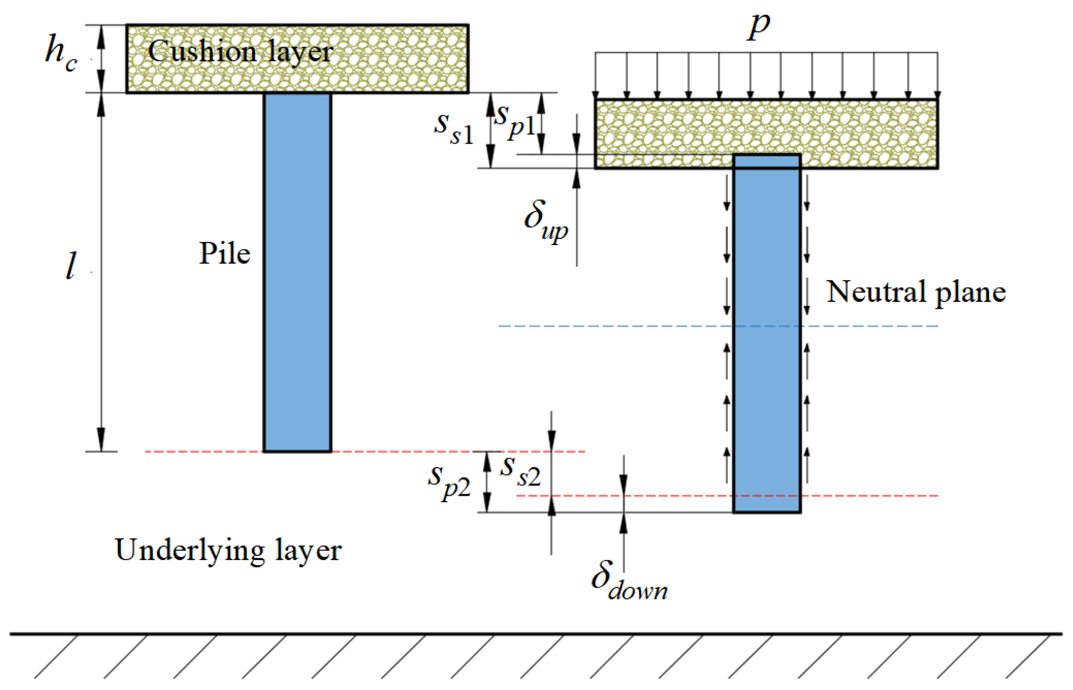
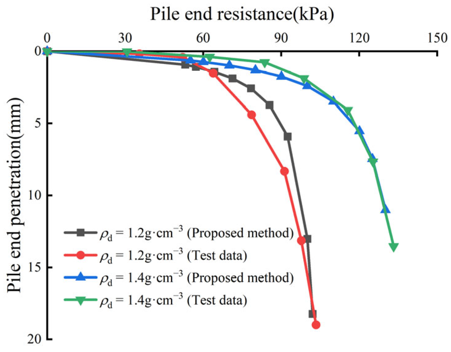
- Pile top load and upward penetration deformation conform to a linear relationship. The relationship between pile end resistance and downward penetration deformation is hyperbolic.
2.2. Model of the Unit Cell
2.3. Mechanism of Pile–Soil–Cushion Interaction
3. Analysis of Pile–Soil Interaction
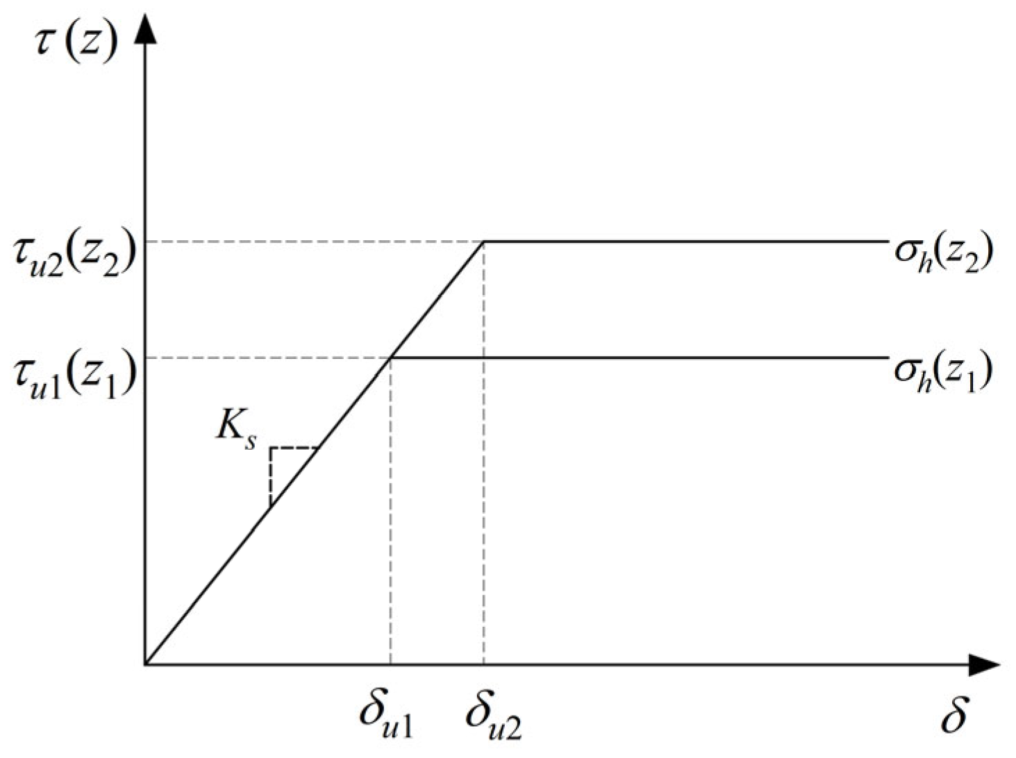
3.1. Skin Friction Distribution Model
3.2. Pile End Load Transfer Model
4. Settlement Calculation of Composite Foundation
4.1. Compressive Deformation of Reinforcement Area
4.1.1. Vertical Displacement Model of Surrounding Soil
4.1.2. Establishment and Solution of Differential Equations for the Unit Cell
4.2. The Upward and Downward Penetrations of Pile
4.3. Settlement of the Underlying Layer of Composite Foundation
5. Determination of Calculation Parameters
5.1. Pile–Soil Load Sharing
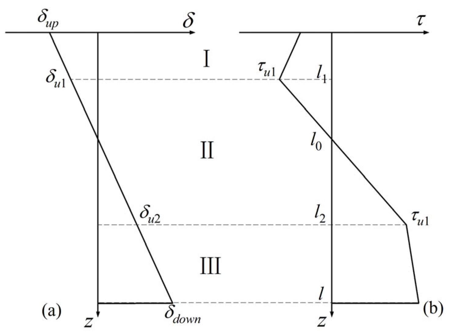
5.2. Elastic and Plastic Zone Play Depth l1, l0, l2 and τ1, τ2
6. Example Validation
6.1. Field Test Validation
6.2. Model Test Validation
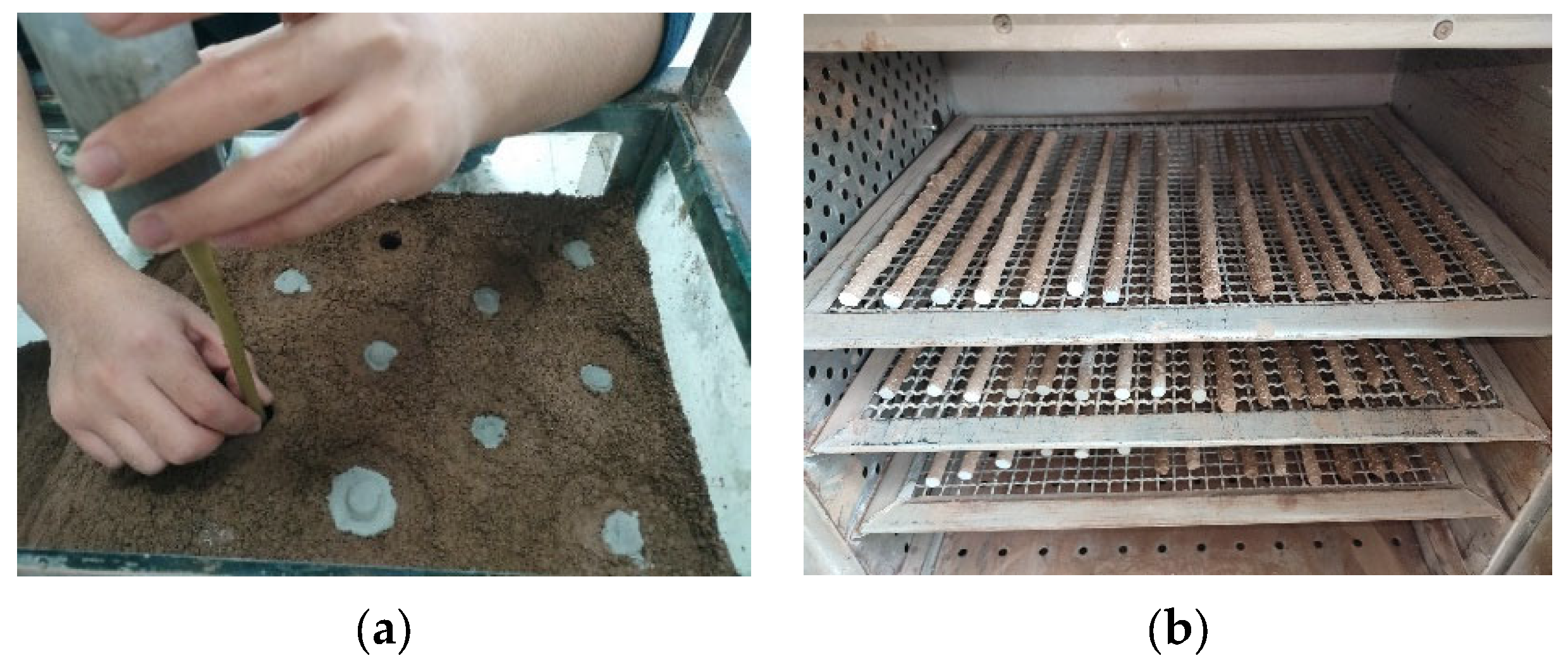
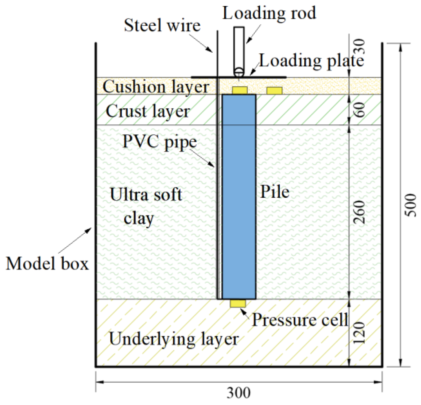
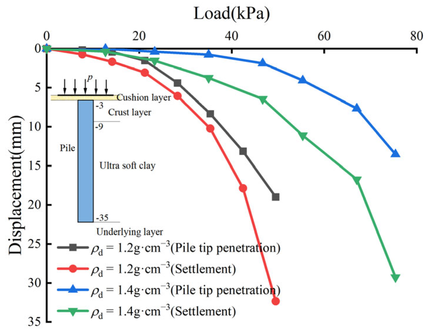
6.2.1. Introduction to Model Tests
6.2.2. Analysis of Model Test Results
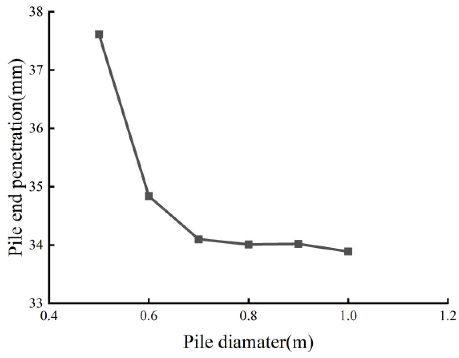
6.3. Analysis of Influencing Factors of Pile End Penetration
7. Conclusions
- (1)
- For ultra-soft soil composite foundation reinforced by semi-rigid piles, by assuming a linear distribution model in the elastic zone and nonuniform one in plastic zone of skin friction, the upward and downward penetrations of pile, and the pile–soil sliding characteristics are considered. An analytical expression for the settlement calculation of semi-rigid pile composite foundation under embankment loading is derived by using the differential equation for pile–soil load transfer of the unit cell.
- (2)
- The validity of the settlement calculation formula of semi-rigid pile composite foundation is verified through in-site measurement and model tests. The theoretical calculation results are in good agreement with the results of field tests and model tests.
- (3)
- The test results show that the settlement stability time of the ultra-soft soil composite foundation is longer, and the settlement is large. Through model tests, it was found that the semi-rigid pile end is penetrated in the ultra-soft soil composite foundation. The relationship between pile end resistance and pile end penetration is hyperbolic.
- (4)
- Through the analysis of the influencing factors of the different compression moduli of the underlying layer and pile diameters on the pile end penetration, it was found that the compression modulus of the underlying layer has a great influence on the pile end penetration. The lower the compression modulus of the underlying layer, the larger the pile end penetration. The larger the pile diameter, the smaller the pile end penetration.
- (5)
- In the design work for composite foundations, increasing the pile diameter and placing the pile end in a high compression modulus soil layer can be used to reduce the pile end penetration, so as to reduce the compression deformation of the surrounding soil.
Author Contributions
Funding
Data Availability Statement
Acknowledgments
Conflicts of Interest
References
- Bo, M.W.; Choa, V.; Wong, K. Reclamation and soil improvement on ultra-soft soil. Proc. Inst. Civ. Eng. Ground Improv. 2005, 9, 23–31. [Google Scholar] [CrossRef]
- Ye, G.; Guo, S.; Zhu, Y. Analysis on engineering property of super soft soil. China Harb. Eng. 2010, 170, 1–9. [Google Scholar]
- Lei, H.; Li, B.; Lu, H.; Ren, Q. Dynamic deformation behavior and cyclic degradation of ultrasoft soil under cyclic loading. J. Mater. Civ. Eng. 2016, 28, 04016135. [Google Scholar] [CrossRef]
- Fan, N.; Nian, T.-K.; Guo, X.-S.; Jiao, H.-B.; Lu, S. Piecewise strength model for three types of ultra-soft fine-grained soils. Soils Found. 2020, 60, 778–790. [Google Scholar] [CrossRef]
- Jin, H.; Yuan, D.; Jin, D.; Wu, J.; Wang, X.; Han, B.; Mao, J. Shield kinematics and its influence on ground settlement in ultra-soft soil: A case study in Suzhou. Can. Geotech. J. 2022, 59, 1887–1900. [Google Scholar] [CrossRef]
- Lei, H.Y.; Wang, L.; Zhang, W.D.; Jiang, M.J.; Bo, Y.; Song, W.F.; Cao, Q.G. Geotechnical properties of the South China Sea soft soil: A comparative study with the soils from Bohai Sea and Yellow Sea. Bull. Eng. Geol. Environ. 2023, 82, 158. [Google Scholar] [CrossRef]
- Ma, L.; Shen, S.L.; Luo, C.Y.; Xu, Y.S. Field Evaluation on the Strength Increase of Marine Clay under Staged Construction of Embankment. Mar. Georesources Geotechnol. 2011, 29, 317–332. [Google Scholar] [CrossRef]
- Chai, J.C.; Shrestha, S.; Hino, T. Failure of an Embankment on Soil-Cement Column-Improved Clay Deposit: Investigation and Analysis. J. Geotech. Geoenviron. Eng. 2019, 145, 05019006. [Google Scholar] [CrossRef]
- Choa, V.; Bo, M. Deformation of ultra-soft soil. In Soft Ground Engineering in Coastal Areas; CRC Press: London, UK, 2003. [Google Scholar]
- Arulrajah, A.; Bo, M.W. Characteristics of Singapore marine clay at Changi. Geotech. Geol. Eng. 2008, 26, 431–441. [Google Scholar] [CrossRef]
- Horpibulsuk, S.; Chinkulkijniwat, A.; Cholphatsorn, A.; Suebsuk, J.; Liu, M.D. Consolidation behavior of soil-cement column improved ground. Comput. Geotech. 2012, 43, 37–50. [Google Scholar] [CrossRef]
- Bergado, D.T.; Chaiyaput, S.; Jamsawang, P. Full-Scale Embankment in Soft Bangkok Clay Using Jet Grouted Cement Mixing Piles. In Practices and Trends in Ground Improvement Techniques; Springer: Berlin/Heidelberg, Germany, 2022; pp. 57–79. [Google Scholar]
- Hong, Z.; Shen, S.; Deng, Y.; Negami, T. Loss of soil structure for natural sedimentary clays. Proc. Inst. Civ. Eng. Geotech. Eng. 2007, 160, 153–159. [Google Scholar] [CrossRef]
- Hong, Z.S.; Zeng, L.L.; Cui, Y.J.; Cai, Y.Q.; Lin, C. Compression behaviour of natural and reconstituted clays. Geotechnique 2012, 62, 291–301. [Google Scholar] [CrossRef]
- Shen, S.L.; Xu, Y.S. Numerical evaluation of land subsidence induced by groundwater pumping in Shanghai. Can. Geotech. J. 2011, 48, 1378–1392. [Google Scholar] [CrossRef]
- Yin, Z.Y.; Yin, J.H.; Huang, H.W. Rate-Dependent and Long-Term Yield Stress and Strength of Soft Wenzhou Marine Clay: Experiments and Modeling. Mar. Georesources Geotechnol. 2015, 33, 79–91. [Google Scholar] [CrossRef]
- Tashiro, M.; Nguyen, S.H.; Inagaki, M.; Yamada, S.; Noda, T. Simulation of large-scale deformation of ultra-soft peaty ground under test embankment loading and investigation of effective countermeasures against residual settlement and failure. Soils Found. 2015, 55, 343–358. [Google Scholar] [CrossRef]
- Jamsawang, P.; Voottipruex, P.; Boathong, P.; Mairaing, W.; Horpibulsuk, S. Three-dimensional numerical investigation on lateral movement and factor of safety of slopes stabilized with deep cement mixing column rows. Eng. Geol. 2015, 188, 159–167. [Google Scholar] [CrossRef]
- Ko, J.; Jeong, S.; Kim, J. Application of a Coupled Eulerian-Lagrangian Technique on Constructability Problems of Site on Very Soft Soil. Appl. Sci. 2017, 7, 1080. [Google Scholar] [CrossRef]
- Shen, S.-L.; Miura, N.; Koga, H. Interaction mechanism between deep mixing column and surrounding clay during installation. Can. Geotech. J. 2003, 40, 293–307. [Google Scholar] [CrossRef]
- Jiang, Y.; Han, J.; Zheng, G. Numerical analysis of a pile-slab-supported railway embankment. Acta Geotech. 2014, 9, 499–511. [Google Scholar] [CrossRef]
- Wu, P.C.; Chen, W.B.; Feng, W.Q.; Yin, J.H.; Ho, T.O.; Huang, S.R. Load transfer mechanism of geotextile-reinforced sand layer over semirigid column-improved soft soil. Acta Geotech. 2024, 19, 2855–2871. [Google Scholar] [CrossRef]
- Miao, L.C.; Wang, F.; Lv, W.H. A Simplified Calculation Method for Stress Concentration Ratio of Composite Foundation with Rigid Piles. KSCE J. Civ. Eng. 2018, 22, 3263–3270. [Google Scholar] [CrossRef]
- Yi, Y.L.; Liu, S.Y.; Puppala, A.J. Bearing capacity of composite foundation consisting of T-shaped soil-cement column and soft clay. Transp. Geotech. 2018, 15, 47–56. [Google Scholar] [CrossRef]
- Zhou, S.H.; Shan, Y.; Wu, Z.Y.; Zhao, W.; Yang, L.C.; Lin, Y.W. Lateral deformation of high-speed railway foundation induced by adjacent embankment construction in soft soils: Numerical and field study. Transp. Geotech. 2023, 41, 101005. [Google Scholar] [CrossRef]
- Pye, N.; O’Brien, A.; Essler, R.; Adams, D. Laboratory and field trials for deep dry soil mixing to stabilize a live railway embankment across Thrandeston bog. In Grouting and Deep Mixing 2012; ASCE Press: Baltimore, MD, USA, 2012; pp. 554–564. [Google Scholar]
- Stewart, M.E.; Navin, M.P.; Filz, G.M. Analysis of a column-supported test embankment at the I-95/Route 1 interchange. In Geotechnical Engineering for Transportation Projects; ASCE Press: Baltimore, MD, USA, 2004; pp. 1337–1346. [Google Scholar]
- Dahlström, M. Dry soil mixing. In Ground Improvement; Kirsch, K., Bell, A., Eds.; CRC Press: London, UK; Taylor & Francis Group: Abingdon, UK, 2013; pp. 482–485. [Google Scholar]
- Jamsawang, P.; Phongphinittana, E.; Voottipruex, P.; Bergado, D.T.; Jongpradist, P. Comparative performances of two- and three-dimensional analyses of soil-cement mixing columns under an embankment load. Mar. Georesources Geotechnol. 2019, 37, 852–869. [Google Scholar] [CrossRef]
- Liyanapathirana, D. A case study of a dcm column-supported embankment over soft clay. Int. J. Geotech. Eng. 2022, 16, 357–366. [Google Scholar] [CrossRef]
- Dehghanbanadaki, A.; Rashid, A.S.A.; Ahmad, K.; Yunus, N.Z.M.; Shahu, J.T.; Mohanty, M. Ultimate Bearing Capacity of Soft Soil Improved by DCM Columns: A Comparative Review. KSCE J. Civ. Eng. 2022, 26, 2653–2661. [Google Scholar] [CrossRef]
- Chen, S.Y.; Guan, Y.F.; Dai, J.Q. Behaviour of anchored sheet pile quay stabilized with deep cement mixing columns in soft soil: Centrifuge and numerical modelling. Comput. Geotech. 2023, 160, 105504. [Google Scholar] [CrossRef]
- Shen, K.; Zhang, H.; Liu, J.; Zhao, X.; Zhang, Y. Offshore Wind Turbine Pile Foundation Reinforcement with Cement-Soil Mixing Method. SSRN 2024. [Google Scholar] [CrossRef]
- Yapage, N.N.S.; Liyanapathirana, D.S.; Kelly, R.B.; Poulos, H.G.; Leo, C.J. Numerical Modeling of an Embankment over Soft Ground Improved with Deep Cement Mixed Columns: Case History. J. Geotech. Geoenviron. Eng. 2014, 140, 04014062. [Google Scholar] [CrossRef]
- Rowe, R.K.; Liu, K.W. Three-dimensional finite element modelling of a full-scale geosynthetic-reinforced, pile-supported embankment. Can. Geotech. J. 2015, 52, 2041–2054. [Google Scholar] [CrossRef]
- Bergado, D.; Noppadol, P.; Lorenzo, G.A. Bearing and compression mechanism of DMM pile supporting reinforced bridge approach embankment on soft and subsiding ground. In Proceedings of the 16th International Conference on Soil Mechanics and Geotechnical Engineering; Mill Press: Rotterdam, The Netherlands, 2005; pp. 1149–1153. [Google Scholar]
- Ariyarathne, P.; Liyanapathirana, S.; Leo, C.J. Load transfer mechanism in geosynthetic reinforced pile-supported embankments: Three dimensional numerical modelling. In Proceedings of the GeoManitoba: Building on the Past: Proceedings of the 65th Canadian Geotechnical Conference, Winnipeg, MB, Canada, 30 September–3 October 2012. [Google Scholar]
- Arulrajah, A.; Abdullah, A.; Bo, M.W.; Bouazza, A. Ground improvement techniques for railway embankments. Proc. Inst. Civ. Eng. Ground Improv. 2009, 162, 3–14. [Google Scholar] [CrossRef]
- Fagundes, D.F.; Almeida, M.S.S.; Thorel, L.; Blanc, M. Load transfer mechanism and deformation of reinforced piled embankments. Geotext. Geomembr. 2017, 45, 1–10. [Google Scholar] [CrossRef]
- Xu, C.; Ye, G. Deformation and bearing capacity of composite foundation with cement-soil mixed piles. Chin. J. Geotech. Eng. 2005, 27, 600–603. [Google Scholar]
- Alamgir, M.; Miura, N.; Poorooshasb, H.; Madhav, M. Deformation analysis of soft ground reinforced by columnar inclusions. Comput. Geotech. 1996, 18, 267–290. [Google Scholar] [CrossRef]
- Yang, T. Settlement Analysis of Composite Ground Improved by Flexible Floating Piles under Road Embankment. Chin. J. Geotech. Eng. 2000, 22, 741–743. [Google Scholar]
- Liu, J.; Zhang, K. Load Transfer Law and Deformation Calculating of the Composite Foundation. China J. Highw. Transp. 2004, 17, 20–23. [Google Scholar] [CrossRef]
- Zhang, Z.; Rao, F.R.; Ye, G.B. Design method for calculating settlement of stiffened deep mixed column-supported embankment over soft clay. Acta Geotech. 2020, 15, 795–814. [Google Scholar] [CrossRef]
- Lu, W.; Yu, J.; Gong, X. Analytical Method for Pile Composite Ground under Flexible Foundation. Chin. J. Rock. Mech. Eng. 2010, 29, 401–408. [Google Scholar]
- Chen, R.P.; Chen, Y.M.; Han, J.; Xu, Z.Z. A theoretical solution for pile-supported embankments on soft soils under one-dimensional compression. Can. Geotech. J. 2008, 45, 611–623. [Google Scholar] [CrossRef]
- Liu, C. Analysis of Working Behavior of Composite Ground under Flexible Foundation. Master’s Thesis, Zhejiang University, Hangzhou, China, 2008. [Google Scholar]
- Chen, S.; Ye, H.; Zhang, W.; Wei, W. Settlement analysis of flexible pile composite foundation under embankment load. Chin. J. Rock Mech. Eng. 2020, 41, 3077–3086. [Google Scholar] [CrossRef]
- Balaam, N.; Booker, J.R. Analysis of rigid rafts supported by granular piles. Int. J. Numer. Anal. Methods Geomech. 1981, 5, 379–403. [Google Scholar] [CrossRef]
- Alonso, E.; Josa, A.; Ledesma, A. Negative skin friction on piles: A simplified analysis and prediction procedure. Geotechnique 1984, 34, 341–357. [Google Scholar] [CrossRef]
- Wong, K.; Teh, C. Negative skin friction on piles in layered soil deposits. J. Geotech. Eng. 1995, 121, 457–465. [Google Scholar] [CrossRef]
- Sharo, A.; Al-Shorman, B.; Baker, M.B.; Nusier, O.; Alawneh, A. New approach for predicting the load-displacement curve of axially loaded piles in sand. Case Stud. Constr. Mater. 2022, 17, e01674. [Google Scholar] [CrossRef]
- Jiu, Y.Z.; Gao, Y.F.; Lei, F.G.; Zhu, Y.Z.; Zhang, Z.Z. Nonlinear Analysis of Bearing Characteristics of Stiffened Deep Cement Mixing Piles under Vertical Loading. Buildings 2024, 14, 816. [Google Scholar] [CrossRef]
- Randolph, M.F.; Wroth, C. An analysis of the vertical deformation of pile groups. Geotechnique 1979, 29, 423–439. [Google Scholar] [CrossRef]
- Potyondy, J.G. Skin friction between various soils and construction materials. Geotechnique 1961, 11, 339–353. [Google Scholar] [CrossRef]
- Burland, J. Shaft Friction of Piles in Clay—A Simple Fundamental Approach; Ground Engineering: Brentwood, UK, 1973; Volume 6, pp. 30–42. [Google Scholar]
- Zhang, L.; Zhao, M.H.; Shi, C.J.; Zhao, H. Settlement Calculation of Composite Foundation Reinforced with Stone Columns. Int. J. Geomech. 2013, 13, 248–256. [Google Scholar] [CrossRef]
- Brooker, E.W.; Ireland, H.O. Earth pressures at rest related to stress history. Can. Geotech. J. 1965, 2, 1–15. [Google Scholar] [CrossRef]
- Lee, J.; Salgado, R. Determination of pile base resistance in sands. J. Geotech. Geoenviron. Eng. 1999, 125, 673–683. [Google Scholar] [CrossRef]
- Yasufuku, N.; Hyde, A. Pile end-bearing capacity in crushable sands. Geotechnique 1995, 45, 663–676. [Google Scholar] [CrossRef]
- Lehane, B.; Gavin, K. Base resistance of jacked pipe piles in sand. J. Geotech. Geoenviron. Eng. 2001, 127, 473–480. [Google Scholar] [CrossRef]
- Mao, W.W.; Hamaguchi, H.; Koseki, J. Discrimination of Particle Breakage below Pile Tip after Model Pile Penetration in Sand Using Image Analysis. Int. J. Geomech. 2020, 20, 04019142. [Google Scholar] [CrossRef]
- Zhang, C.; Nguyen, G.D.; Einav, I. The end-bearing capacity of piles penetrating into crushable soils. Geotechnique 2013, 63, 341–354. [Google Scholar] [CrossRef]
- Peng, Y.; Yin, Z.Y.; Ding, X.M. Analysis of particle corner-breakage effect on pile penetration in coral sand: Model tests and DEM simulations. Can. Geotech. J. 2022, 60, 749–765. [Google Scholar] [CrossRef]
- Hirayama, H. Load-settlement analysis for bored piles using hyperbolic transfer functions. Soils Found. 1990, 30, 55–64. [Google Scholar] [CrossRef]
- Yasufuku, N.; Ochiai, H.; Ohno, S. Pile end-bearing capacity of sand related to soil compressibility. Soils Found. 2001, 41, 59–71. [Google Scholar] [CrossRef]
- Bohn, C.; dos Santos, A.L.; Frank, R. Development of Axial Pile Load Transfer Curves Based on Instrumented Load Tests. J. Geotech. Geoenviron. Eng. 2017, 143, 04016081. [Google Scholar] [CrossRef]
- Madhira, M.; Kiran, K.V. A Method to Estimate Shaft and Base Responses of a Pile from Pile Load Test Results. Geotech. Eng. 2019, 50, 118–123. [Google Scholar]
- Vedhasri, S.; Rao, C.N.; Madhav, M. Estimation of shaft and base responses of a pile from pile load tests. Mater. Today Proc. 2022, 51, 2592–2598. [Google Scholar] [CrossRef]
- Clough, G.W.; Duncan, J.M. Finite element analyses of retaining wall behavior. J. Soil Mech. Found. Div. 1971, 97, 1657–1673. [Google Scholar] [CrossRef]
- Zhang, Q.Q.; Zhang, Z.M. A simplified nonlinear approach for single pile settlement analysis. Can. Geotech. J. 2012, 49, 1256–1266. [Google Scholar] [CrossRef]
- Randolph, M.F.; Wroth, C.P. Analysis of deformation of vertically loaded piles. J. Geotech. Eng. Div. 1978, 104, 1465–1488. [Google Scholar] [CrossRef]
- Vesić, A.S. Expansion of cavities in infinite soil mass. J. Soil Mech. Found. Div. 1972, 98, 265–290. [Google Scholar] [CrossRef]
- Cao, L.; Teh, C.; Chang, M. Undrained cavity expansion in modified Cam clay I: Theoretical analysis. Geotechnique 2001, 51, 323–334. [Google Scholar] [CrossRef]
- Li, Y. A Study on Spheric Cavity Expansion and Static Piling in Soils. Ph.D. Thesis, Zhejiang University, Hangzhou, China, 2001. [Google Scholar]
- Xu, Z. Elasticity, 5th ed.; Higher Education Press (PRC): Beijing, China, 2016; Volume 1, pp. 73–80. [Google Scholar]
- Gong, X. Plastic Soil Plastics Mechanics, 2nd ed.; Zhejiang University Press: Hangzhou, China, 1999; pp. 262–266. [Google Scholar]
- Liu, J.; Zhang, M.; Zhao, H.; Wang, J. Computational simulation of jacking force based on spherical cavity expansion theory and friction fatigue effect. Rock Soil Mech. 2009, 30, 1181–1185. [Google Scholar] [CrossRef]
- Knappett, J.A.; Reid, C.; Kinmond, S.; O’Reilly, K. Small-Scale Modeling of Reinforced Concrete Structural Elements for Use in a Geotechnical Centrifuge. J. Struct. Eng. 2011, 137, 1263–1271. [Google Scholar] [CrossRef]
- Zhang, C. The Research on Load Transfer Mechanism and Settlement Calculation Method of Pile-Supported Embankment. Ph.D. Thesis, Hunan University, Changsha, China, 2021. [Google Scholar]


| Embankment | Cushion Layer | Crust Layer | Ultra-Soft Soil | Underlying Layer | |
|---|---|---|---|---|---|
| Thickness, h (m) | 4 | 0.3 | 1.5 | 13.5 | 10 |
| Unit weight, γ (kN/m3) | 20 | 21 | 17 | 15.3 | 18.5 |
| Compression modulus, Es1–2 (MPa) | - | 150 | 3.4 | 1.3 | 7.2 |
| Poisson’s ratio, ν | - | - | 0.3 | 0.4 | 0.3 |
| Cohesion, c (kPa) | - | - | 12.3 | 6 | 28.1 |
| Friction angle, φ (degree) | - | - | 4.2 | 3.5 | 12.3 |
| Projects | CSF (mm) | Relative Error of CSF | Reinforced Area | Underlying Layer | PSSR | Relative Error of PSSR | ||
|---|---|---|---|---|---|---|---|---|
| Settlement (mm) | Percentage of CSF | Settlement (mm) | Percentage of CSF | |||||
| Measured value | 533.97 | - | - | - | - | - | 1.75 | - |
| Calculated value | 563.00 | 5.44% | 453.60 | 80.57% | 109.40 | 19.43% | 1.25 | 28.57% |
| Soils | γ (kN/m3) | w (%) | wL (%) | wp (%) | e | Es (MPa) | φ (°) | cq (kPa) |
|---|---|---|---|---|---|---|---|---|
| Clay | 17.2 | 55.3 | 62.4 | 27.3 | 1.558 | 0.581 | 4.2 | 12.2 |
| Mucky | 15.3 | 83.7 | 62.4 | 27.3 | 2.173 | 0.516 | 3.5 | 6.0 |
| Silty clay | 18.0 | 16.1 | 29.6 | 16.1 | 0.735 | 0.8/1 * | 12.3 | 28.1 |
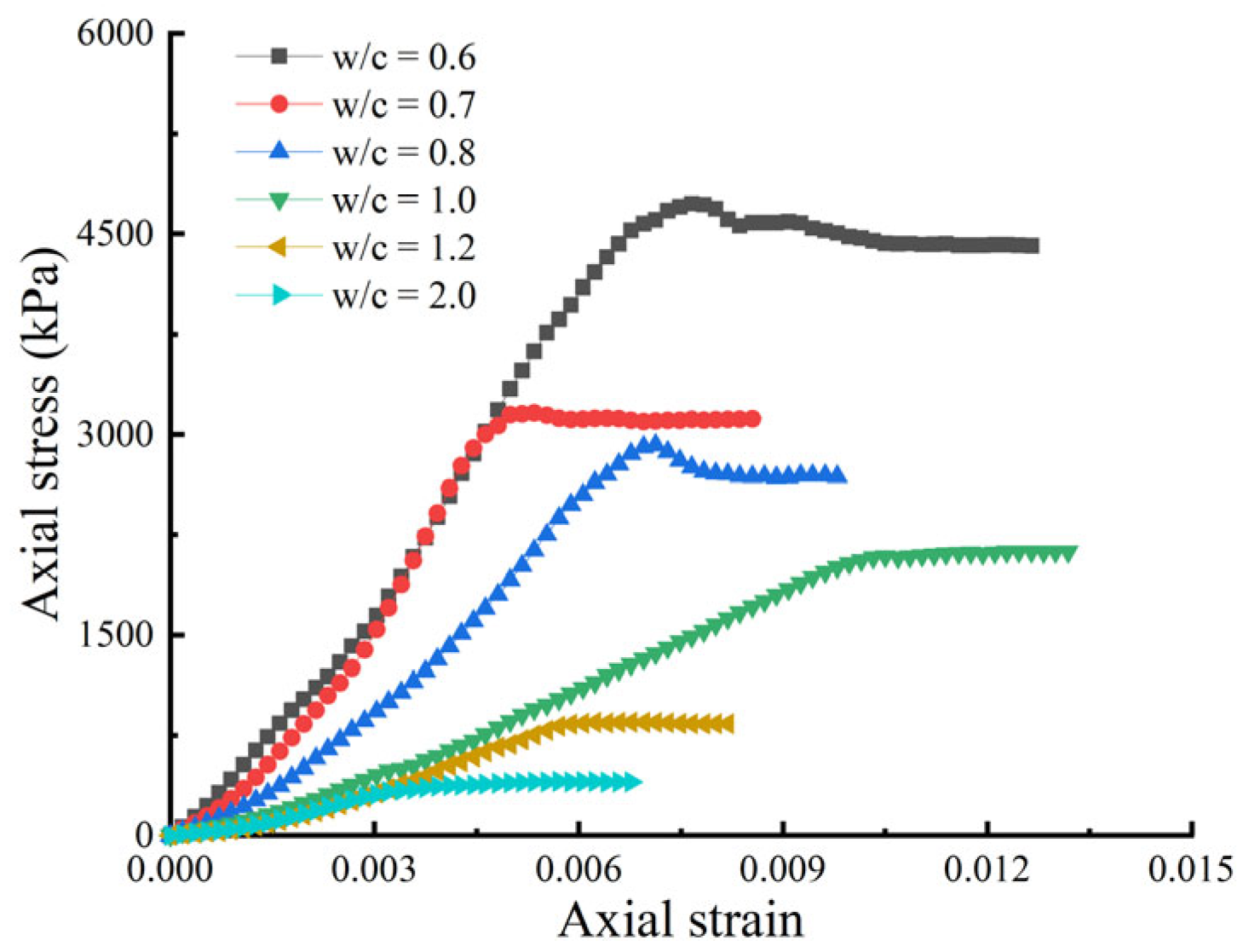
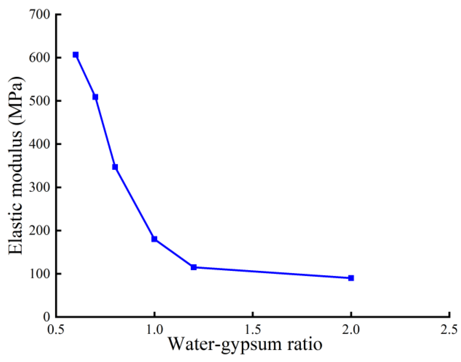
| Water–Gypsum Ratio | Pult (kN) | fult (MPa) | f50 (MPa) | E50 (MPa) |
|---|---|---|---|---|
| 0.6 | 9.3 | 4.7 | 2.4 | 607 |
| 0.7 | 6.1 | 3.1 | 1.6 | 509 |
| 0.8 | 5.7 | 2.9 | 1.5 | 347 |
| 1.0 | 4.1 | 2.1 | 1.0 | 180 |
| 1.2 | 1.7 | 0.8 | 0.4 | 115 |
| 2.0 | 0.8 | 0.4 | 0.2 | 90 |
Disclaimer/Publisher’s Note: The statements, opinions and data contained in all publications are solely those of the individual author(s) and contributor(s) and not of MDPI and/or the editor(s). MDPI and/or the editor(s) disclaim responsibility for any injury to people or property resulting from any ideas, methods, instructions or products referred to in the content. |
© 2024 by the authors. Licensee MDPI, Basel, Switzerland. This article is an open access article distributed under the terms and conditions of the Creative Commons Attribution (CC BY) license (https://creativecommons.org/licenses/by/4.0/).
Share and Cite
Cao, F.; Ye, C.; Wu, Z.; Zhao, Z.; Sun, H. Settlement Calculation of Semi-Rigid Pile Composite Foundation on Ultra-Soft Soil under Embankment Load. Buildings 2024, 14, 1954. https://doi.org/10.3390/buildings14071954
Cao F, Ye C, Wu Z, Zhao Z, Sun H. Settlement Calculation of Semi-Rigid Pile Composite Foundation on Ultra-Soft Soil under Embankment Load. Buildings. 2024; 14(7):1954. https://doi.org/10.3390/buildings14071954
Chicago/Turabian StyleCao, Fengxu, Chaoliang Ye, Zhenxu Wu, Zitong Zhao, and Hao Sun. 2024. "Settlement Calculation of Semi-Rigid Pile Composite Foundation on Ultra-Soft Soil under Embankment Load" Buildings 14, no. 7: 1954. https://doi.org/10.3390/buildings14071954