Article

Computational and Experimental Substantiation of Strengthening Reinforced Concrete Structures with Composite Materials of Power Plants under Seismic Action

1
Department of Hydraulics and Hydraulic Engineering, Moscow State Construction University of Civil Engineering (National Research University), 26, Yaroslavskoye Shosse, 129337 Moscow, Russia
2
Institute Hydroproject JSC, 2, Volokolamskoye Shosse, 125993 Moscow, Russia
3
Branch NIIES of Institute Hydroproject JSC, 2, Volokolamskoye Shosse, 125993 Moscow, Russia
*
Author to whom correspondence should be addressed.
Buildings 2024, 14(7), 1971; https://doi.org/10.3390/buildings14071971
Submission received: 13 May 2024 / Revised: 10 June 2024 / Accepted: 24 June 2024 / Published: 28 June 2024
(This article belongs to the Section Building Structures)

Abstract

:
In Russia, a significant number of power facilities built in the 1960s and 1970s are located in regions where seismic effects were revised upward. This has led to an increase in the seismicity of the sites of facilities’ locations by magnitude 1–2 (MSK-64) in comparison with the data of design documentation. During the long-term operating period of power facilities, the load-bearing capacity of building structures, as a rule, decreases. This article presents the results of computational and experimental studies of reinforced concrete structures of thermal power plants and hydroelectric power plants for seismic effects in the range of magnitude 4–10 (MSK-64). The computational studies were carried out using ANSYS 16.0 software, and experimental studies were carried out on stands modeling seismic impacts with the help of hydraulic cylinders. The results of the studies showed that cracking of reinforced concrete structures without strengthening occurs at magnitude 6.0 (MSK-64) of seismic impact, and destruction occurs at magnitude 7.5. Thus, the seismic resistance of structures without reinforcement does not meet the requirements for seismic resistance, and strengthening is required. This study considers a variant of strengthening based on external composite reinforcement with CFRP. It is shown that the strengthening of structures with composite material increases their earthquake resistance up to magnitude 9–10 (MSK-64). This article presents recommendations on the CFRP strengthening of building structures of power facilities, both after receiving damage under seismic impact and in a planned manner to increase seismic resistance. The novelty of this work lies in the fact that quantitative results of increasing the seismic resistance of structures depending on the placement and number of layers of composite material are given.

1. Introduction

According to the statistics of the United States Geological Survey (USGS), 12–14 thousand earthquakes with different intensities occur annually in the world. In the Russian Federation, over the last 10 years, nine magnitude 7 (MSK-64) earthquakes have been recorded.
In this context, the issue of ensuring the seismic resistance of TPPs and HPPs is relevant. Taking into account that the service life of power plants is counted in decades, it is necessary to ensure the maintenance of their serviceable and reliable technical conditions during the entire period of operation as well as their compliance with the requirements of current regulatory documentation. For example, power plants built in the 1960s and 1970s are being modernized and operated in Russia. The construction norms and rules that were in force at that time have undergone a number of updates, including SN 8-57 (1957), SNiP II. A.12-62 (1962), and SNiP II-7-81 (1981), as well as updated earthquake intensity maps: OSR-57, OSR-68, and OSR-78. Currently, the OSR-2015 earthquake intensity maps (SP 14.13330.2018) are in effect [1], based on the OSR-97 maps (SNiP II-7-81*) [2]. There are discussions in the scientific community about the need for a new adjustment, with the OSR-2016 maps preliminarily released. Based on an analysis of the data accumulated over the last 50 years, the intensity of seismic impacts on the territory of Russia has increased by magnitude 1–2 (MSK-64).
In addition, during the long-term operation of thermal and hydroelectric power plants, the scheme of operation of building structures receives significant changes relative to the initial design solutions due to changes in the physical and mechanical characteristics of materials, as well as external loads and impacts.
In this regard, research engineers are faced with the task of ensuring the reliability of hydroelectric and thermal power plants, taking into account the reliability deficit during high-intensity seismic events.
Nowadays, the strengthening of structures of industrial and civil buildings is studied widely enough. Among them, composite materials are widely discussed, providing the necessary strength reserves for building structures without significantly changing their mass-dimensional dimensions.
Studies [3,4,5,6] solve the following problems:
  • The reuse of polymer waste mix (PM) as fillers in calcium silicate to prepare new composites of environmentally friendly polymer concrete;
  • The recycling of plastic waste in the proposed low-energy dicalcium silicate cement to give improved environmentally friendly composites after converting CO2 gas to carbonates, with a reduced carbon footprint;
  • The reuse of plastic waste as aggregate or fiber in cement mortar and concrete manufacturing. The article reviewed the three most significant features of concrete: fresh properties, mechanical strength, and durability;
  • The effect of the quantity of the two main components of fly ash, CaO and SiO2, on the compressive strength of concrete modified with different fly ash contents for various mix proportions.
Studies [7,8] present the following:
  • The results of experimental studies of fiber-reinforced recycled aggregate concrete (FRAC) by adding steel fiber (SF) and polypropylene fiber (PPF) into the RAC matrix. The residual strains under cyclic compression in low-cycle tests with increasing strain amplitude were determined. A predictive model of FRAC behavior, taking into account the content of steel and PPF fibers in concrete, was also developed;
  • The results of cyclic compression tests of SF-reinforced natural aggregate concrete (SF-R-NAC), SF-reinforced RAC (SF-R-RAC), and PPF-reinforced RAC (PPF-R-RAC) with different contents of steel and polypropylene fibers. The pattern of residual strain development was investigated, a relationship between residual strain and unloading strain was proposed, and a modified model of the stress–strain relationship of concrete was developed. A new hysteretic viscous damping model represented by residual strain was proposed, accounting for the fiber content.
The studies presented above are an important component of the reinforced concrete structure literature in the direction of joint work with composite reinforcement materials to increase seismic resistance.
In the study [9], the results of experimental and computational investigations of reinforced concrete beams strengthened by external reinforcement from carbon fiber-reinforced plastic (CFRP) are presented. The nature of failure of all beams under static loading was determined by the crack opening width, formation of secondary cracks, and deflections in the zone of bending moment action with subsequent CFRP peeling. The analytical load–deflection curves and numerical simulation by the finite element method were in good agreement with the experimental behavior of reinforced concrete beams strengthened with CFRP, and a significant potential for strength increase was established. It should be noted that the studies were carried out on reinforced concrete beams under static loads.
The study [10] was carried out on reinforced concrete beams with reinforcement typical of massive structures under static loading: without strengthening and strengthened with carbon tapes. As a result of strengthening by carbon tapes of reinforced concrete beams made of concrete B15 with 0.39% reinforcement, their strength increased on average by 2.06 times; the strength of reinforced concrete beams made of concrete B25 with 0.83% reinforcement increased on average by 1.5 times. At the same time, studies on seismic effects were not carried out. In the work [11], results were presented of studies of reinforced concrete slabs of the installation site of Ayurikin HPP (Ecuador) after the fall of a load weighing 22 tons, under the action of which there was cracking and pushing through in the slab. Carbon composite materials are recommended for the strengthening of reinforced concrete slabs. Study [12] presented the results of strengthening using CFRP in longitudinal and transverse directions, with V-shaped end anchors in the tensile zone of beams. The study was carried out under static loading on linear beam structures. The investigation [13] of beams under repeated loads showed the crack spacing and crack opening width as well as a decrease in the deflection in the middle of the span and an increase in the bearing capacity with increasing prestressing of CFRP sheets. The evaluation of the performance of structures at high temperatures (650 °C) with NSM-CFRP reinforcement showed that over three hours, the shear load-carrying capacity decreased by 20% [14], and it was revealed that the arrangement of the strengthening geometry under 45° was 64.6% more effective than that under 90°. The use of textile-reinforced mortar (TRM) as an external reinforcement can increase the shear capacity of columns in frame structures [15].
In study [16], the results of cyclic tests of structures reinforced with GFRM were summarized. The reinforced specimens showed an increase in strength, which reached values of about 50% compared to unreinforced specimens. The methodology proposed by the authors was suitable for low-rise buildings located in areas with low seismicity. In the study [17], an approach to the reinforcement of building structures based on the use of metal diaphragms counteracting shear deformations caused by seismic events was proposed. A positive effect of the proposed solutions was achieved by labor-intensive and expensive measures for the construction of V- and X-shaped metal reinforcing structures and diaphragms.
The paper [18] presented the development of a post-tensioned precast-reinforced concrete frame with bolted connections of steel slabs (PT-PBSPC) under seismic loads. A total of four experiments were considered, which showed an increase in load-carrying capacity and a decrease in residual deformations after the proposed reinforcement. The numerical studies [19,20] were performed in a nonlinear formulation. The solutions of static and dynamic problems for the following types of reinforcement were considered:
  • Fiberglass reinforcement of columns.
  • Arrangement of steel cantilevers in the middle span of all floors of a frame.
  • Construction of an additional concrete shear wall.
In the research, it was noted that the reinforcement of columns by using FRP increased the strength of the frame and the overall stiffness of the structure. At the same time, the authors did not consider the option of joint reinforcement of columns and slabs.
The results of experiments on the strengthening of reinforced concrete single-span frames under seismic action by means of an additional column and steel struts were presented in the study [21]. The proposed method was effective and simple for the reinforcement of civil buildings. Its implementation in practice, taking into account the installation of additional columns in the existing single-span frame, was rather labor-intensive, expensive, and time-consuming.
Experimental investigations of reinforced concrete columns with axial loading and under seismic action [22] have shown that the strength of reinforced concrete columns can be improved by reinforcement with carbon fiber-reinforced plastic. At the same time, there were no engineering proposals on the technology of reinforcement of the joint connection “column-transom”.
The results of the experimental study [23] showed the effective methods of beam–column connection rehabilitation. A comparison of the characteristics of the original and restored specimens proved that FRP reinforcement could increase the shear resistance and improve the performance of the connection. However, it was found that the anchorage of FRP and possible deformations of the sheathing should be taken into account. In [24], the development of a precast concrete structure with externally anchored BFRP to improve the earthquake resistance of existing frame buildings was presented. The study confirmed the effectiveness of the proposed approach with external BFRP reinforcement to absorb seismic effects.
The effectiveness of carbon fiber composites on a two-story frame under seismic loading was reviewed in [25]. The vibration test results showed the effectiveness of the applied method, including for different natures of column–beam connection operations. A characteristic feature of the research was the calibration of mathematical models based on the results of physical experiments. It was presented in the conclusions that the use of composite materials reduced localized damage while ensuring the strength of the beam-column assembly. In [26], the effectiveness of different reinforcement schemes for increasing the seismic resistance of structures was considered. The authors concluded that in the case of the application of composite external reinforcement, it is necessary to restore all existing elements of the structures.
In [27], the effectiveness of FRP in increasing the seismic resistance of structures was studied. Computational studies using the finite element method were performed. The results confirmed the improvement of structural performance during seismic actions when FRP reinforcement was applied. In the study [28], the combined action of steel reinforcement, reinforcement subjected to corrosion wear, and composite reinforcement was considered on a spatial mathematical model. The authors determined the strengths of reinforced structures under seismic effects and proposed approaches to mathematical modeling. In [29], the results of research on concrete columns in compression with fiberglass reinforcement were presented, and the experiments were compared with analytical models. Mathematical modeling was used in [30] to study the behavior of square and rectangular columns reinforced with FRP materials. The analytical results were in good agreement with the experimental data on the stress–strain relationship. In [31], design parameters for predicting the ultimate axial compressive strain of reinforced concrete columns strengthened with composite materials were investigated. The test results under cyclic axial loading were presented as a database. Thus, [27,28,29,30,31] described a combined approach and combined three-dimensional finite element models and data from physical experiments.
In an experimental study [32], the effect of using three different composite materials to reinforce the “beam-column” connection was investigated. Reinforcement with CFRP reduced the width of the shear crack opening, practically eliminated the formation of diagonal (inclined) cracks, and increased the ultimate bearing capacity in comparison with the control specimens. However, seismic (dynamic) impact was not applied to the experimental specimens.
In [33], the results of experimental and numerical studies to evaluate the seismic resistance of reinforced structures were presented. The authors concluded that carbon fiber reinforcement increases the lateral load-bearing capacity and seismic resistance of structures. The method of reinforcement with composite materials was considered for flat structures and is promising for spatial elements.
The research analyses presented in [3,4,5,6,7,8,9,10,11,12,13,14,15,16,17,18,19,20,21,22,23,24,25,26,27,28,29,30,31,32,33] showed that a set of experiments and calculations were carried out on linear beams and, to a greater extent, frame-reinforced concrete models. In most cases, static loading was applied, and seismic effects were modeled less frequently. The studies were mainly carried out for industrial and civil engineering structures (frame residential buildings). For reinforced-concrete-structure strengthening applications, the following are justified:
  • Metal products with a high load-bearing capacity that require substantial capital investments and labor-intensive work;
  • Fiberglass materials that are affected by the alkaline environment of concrete during long-term operation;
  • Carbon composite CFRP products.
There are a few practical recommendations for the implementation of reinforced concrete structures to strengthen unique objects. Experiments on increasing the seismic resistance of energy facilities (TPPs and HPPs) are not sufficiently covered in the articles, and increasing their seismic resistance in operation for more than 50 years is rarely considered by scientists. At the same time, the requirements for energy facility structure strengthening should be stricter than for industrial and civil engineering facilities due to the disproportionate level of responsibility.
In studies [27,28,29,30,31], a comprehensive assessment approach using the capabilities of mathematical modeling of structures and physical experiments was supported. Vibration platforms for modeling dynamic impacts were most often used. This approach provided good practical results; however, it did not allow for the modeling of high-intensity seismic impacts for large-scale models such as 1:1 or 1:2. Therefore, in the study presented herein, the impact modeling approach using a hydraulic cylinder bench was applied.
Thus, the authors of this article, taking into account the analyzed studies of other scientists, conducted a study aimed at improving the seismic resistance of reinforced concrete load-bearing structures of hydroelectric and thermal power plants under seismic effects of different intensities.
For modeling the key elements of HPP and TPP, structures were selected. The loads acting on them were collected and the most loaded structure was selected. In this case, it was “pressure wall with slab” and “column-transom”, the models of which were made at the scale 1:2. The main objective was to develop the reinforcement of the structures to ensure their compliance with the requirements of the current normative documentation under high-intensity seismic effects. CFRP as a strengthening material was used. Reinforcement and strength parameters of structures were determined on the basis of survey data. The reinforcement class was adopted in accordance with the nomenclature used in the 1960s and 1970s. In addition, the revealed defects of building structures, such as cracks, caverns, and local strength reductions, were included in the calculation studies.
Artificial accelerograms for modeling seismic impacts with an occurrence of once in 500, 1000, and 5000 years were developed. The obtained accelerograms as seismic effects on the developed spatial mathematical models were used. The most loaded structure was selected and its physical model was developed. Loads and boundary conditions were fully correlated with the data obtained by mathematical modeling.
Based on the experimental data, modeling of CFRP reinforcement with different positions of composite tapes was carried out. After that, the optimal variant of reinforcement of the considered structure was selected.
On the basis of the data of mathematical and physical experiments, empirical dependences of strength parameters of the composite material at the level of a seismic impact of high intensity were determined, on the basis of which, the nomogram for the joint connection “column-transom” was constructed.

2. Materials and Methods

This research solved the complex problem of evaluating the seismic resistance of thermal and hydroelectric power plant structures under conditions of increasing seismic loads.
The work was carried out according to the following cycle:
  • Determination of the actual seismicity of the area where the facilities were located, based on the current regulatory and technical documentation and microseismic monitoring data;
  • Determination of the seismic events with an occurrence of once every 500, 1000, and 5000 years;
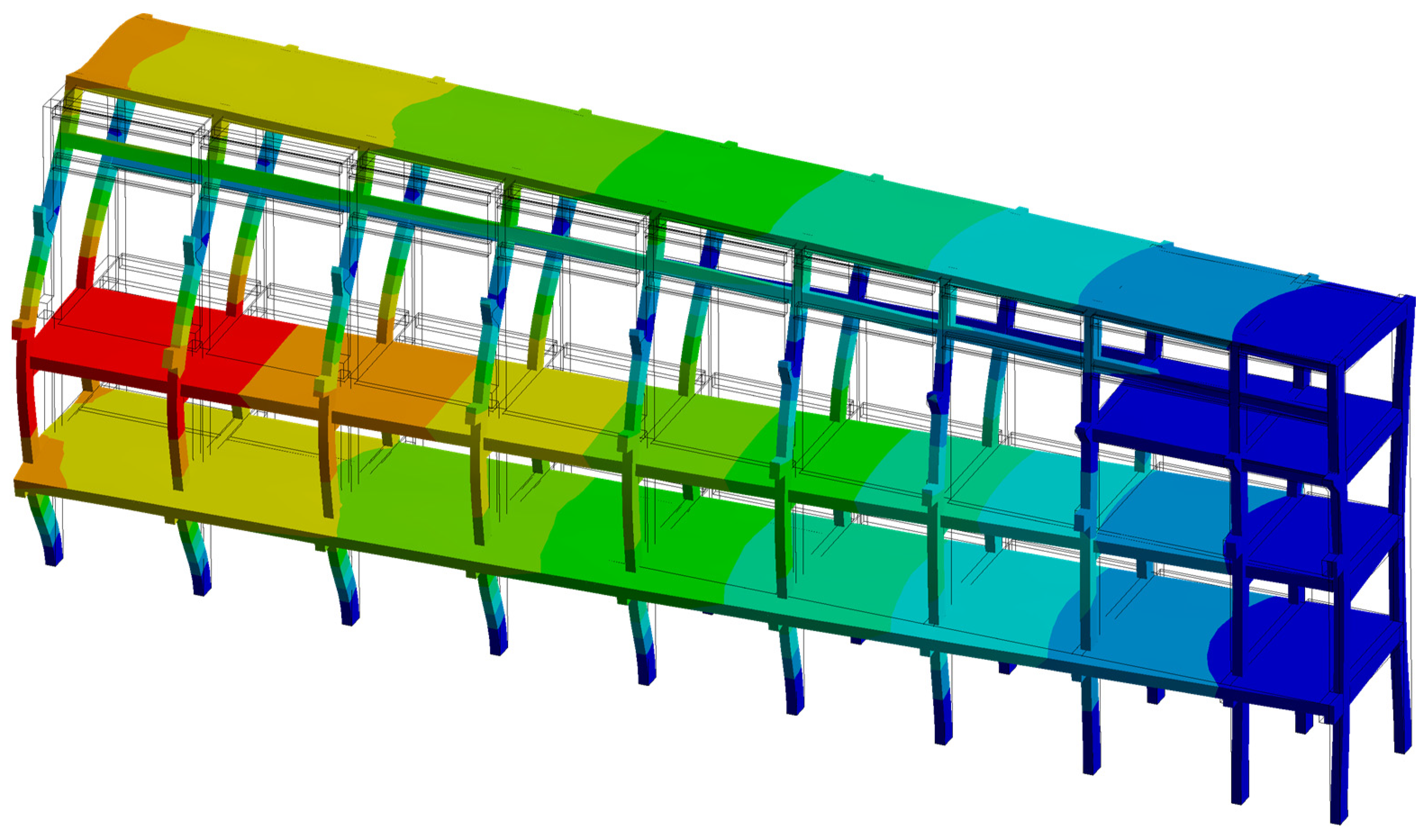
  • Development of spatial mathematical models of TPPs and HPPs;
  • Comprehensive surveys of structures in order to determine the actual strength parameters of concrete as well as the actual reinforcement data of the structures;
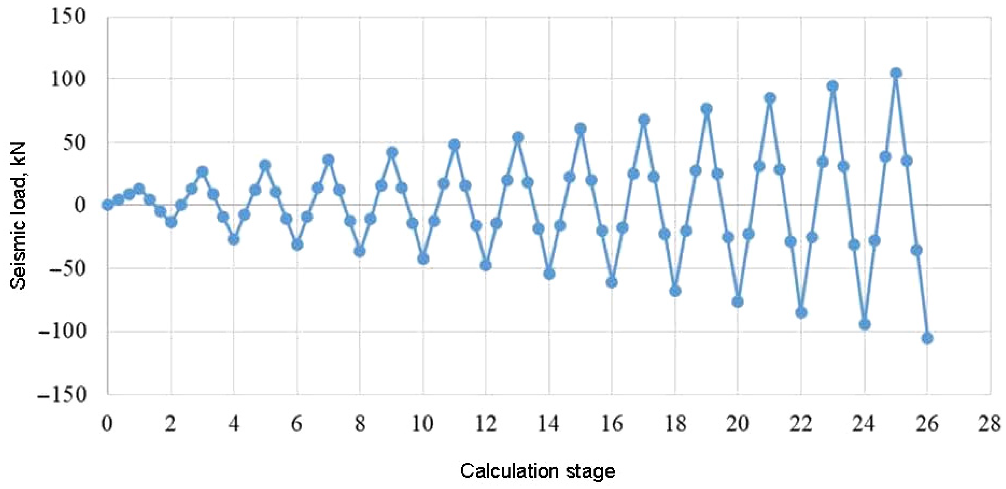
  • Complex calculation studies (ANSYS) taking into account the nonlinear behavior of materials and acting loads;
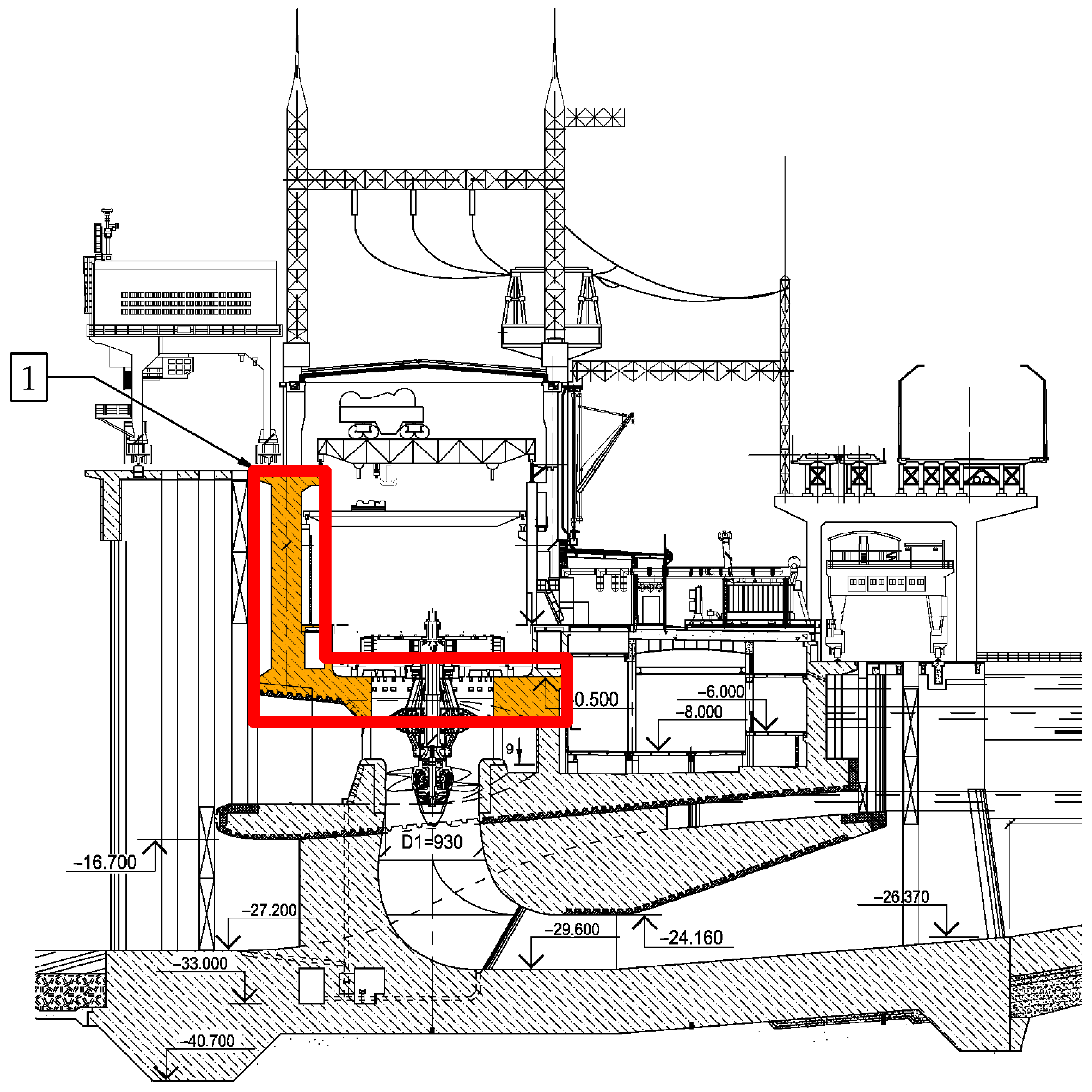
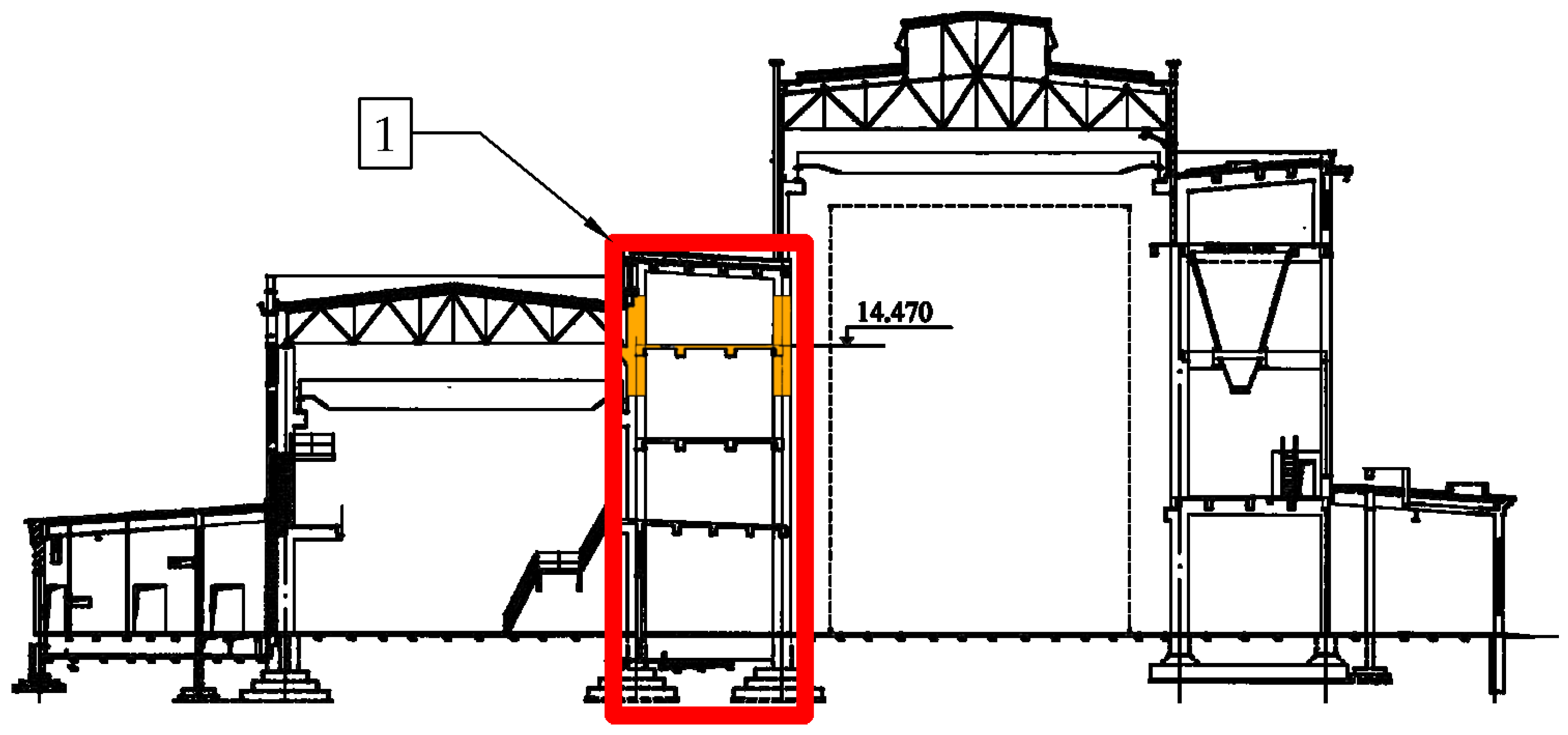
  • Identification of the most loaded typical elements of HPPs and TPPs;
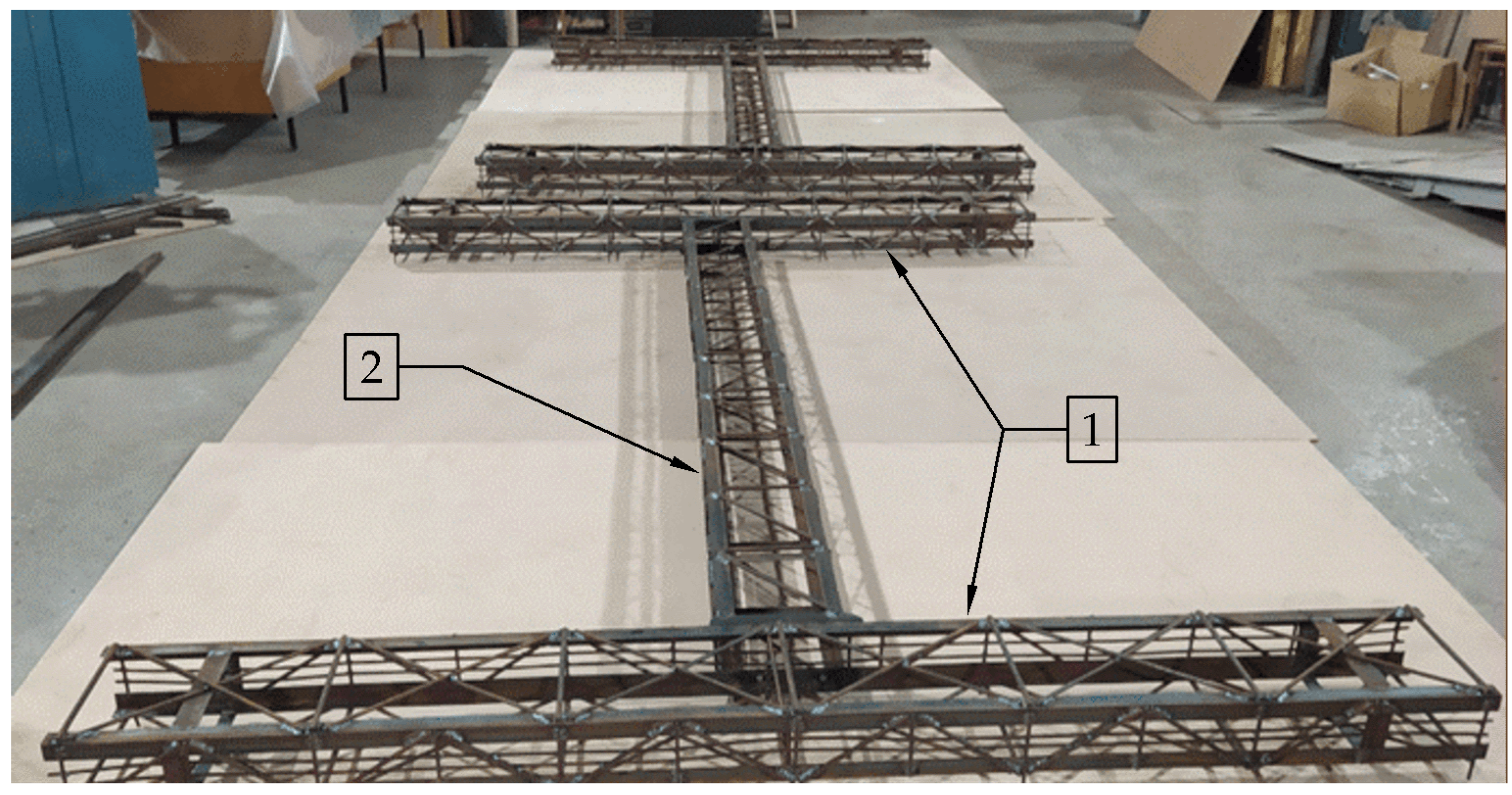
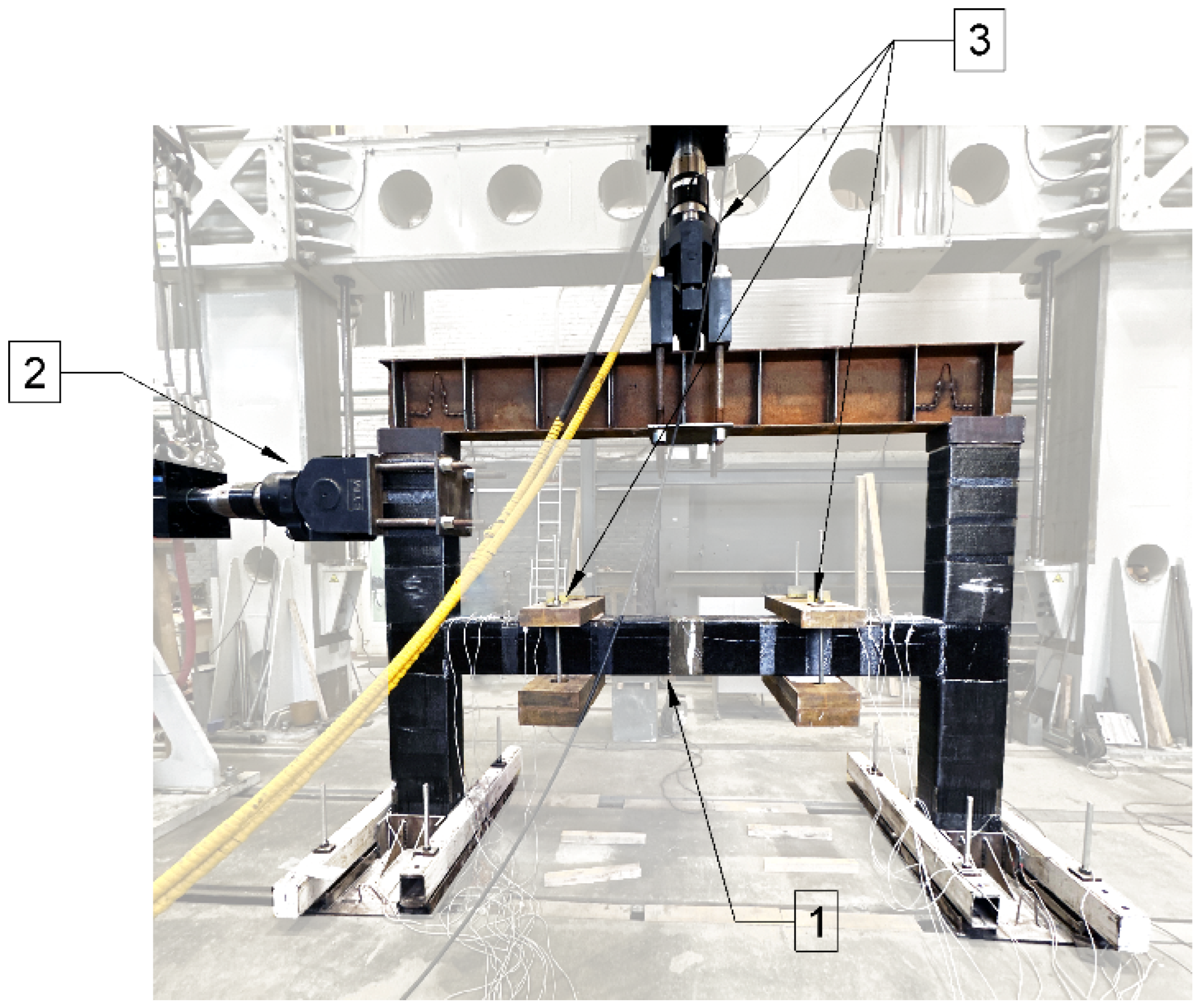
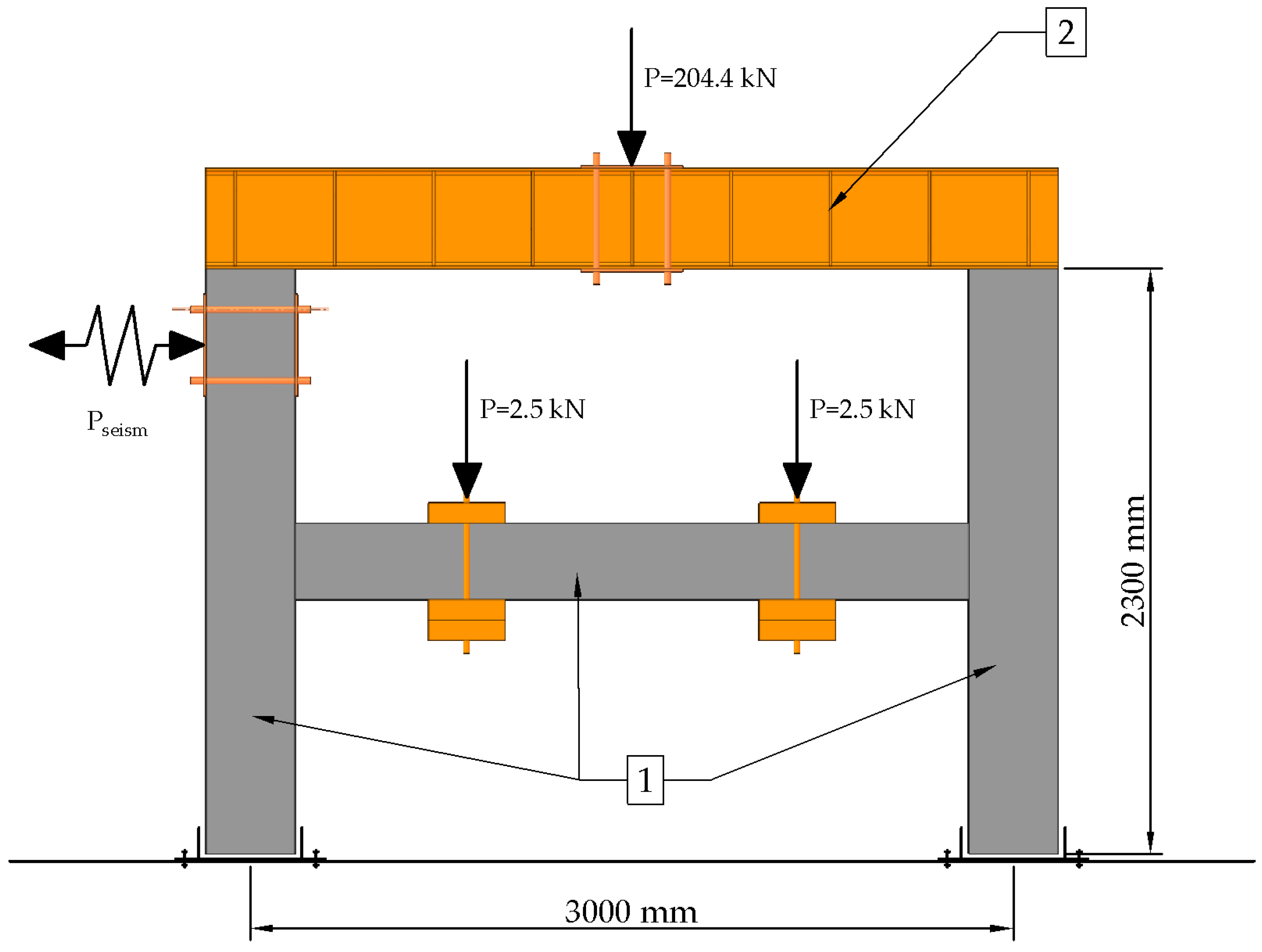
  • Development of the physical models;
  • Experimental investigations of a reinforced concrete frame structure without strengthening under a seismic impact bringing it to failure;
  • Determination of the required composite external strengthening for the earthquake resistance of structures;
  • Experimental investigations of the seismic action of a reinforced concrete frame structure strengthened with composite materials “after earthquake”;
  • Experimental investigations of a reinforced concrete frame structure initially strengthened with composite materials under seismic action.
A detailed specification of the initial seismicity of HPP and TPP sites was carried out using Probabilistic Seismic Hazard Analysis (PSHA) [34,35,36,37,38,39]. The method is based on the estimation of the probability of exceeding a given level of earthquake-induced ground motion at a given point during a given future time period. The product of this analysis is a hazard curve: the dependence of the probability of exceedance on the level of movement. The CRISIS 2015 program was used to directly calculate the impact values [40], developed at the National University of Mexico. The program is freely distributed and regularly updated. CRISIS works with all types of sources and contains in its database most of the known attenuation models up to 2014. In 2015–2016, the CRISIS program was tested at the Pacific Earthquake Engineering Research Center (USA), where it was compared with well-known software, in particular PSHA. The results of the seismic calculations are presented in Table 1. An example of one of the synthesized accelerograms is shown in Figure 1.
Computational studies of the stress–strain state were performed in the engineering simulation software ANSYS, based on the finite element method. The finite element method is one of the most widespread current methods of mathematical modeling for determining the stress–strain state of various industrial and civil objects, as well as complex energy facilities structures. The development of information technologies and industrial software makes it possible to use CUDA parallel computing hardware and software architecture when solving interdisciplinary problems and increases the accuracy and speed of research. In addition, it allows for the solving of complex interdisciplinary problems, taking into account thermal, dynamic, and seismic effects.
The mathematical model of concrete used in the calculations was a model of multilinear kinematic hardening along the stress–strain curves in concrete compression, allowing for cracking (finite elements of SOLID45 type). The three-dimensional Menetrey–Willam model as the concrete fracture model was adopted. It provided a three-parameter fracture surface with the following expression:
f ξ , ρ , θ = 1.5 · ρ f c 2 + m · ρ 6 · f c · r θ , e + ξ 3 · f c c = 0
The reinforcement in the computational model was specified using bar elements (LINK-type finite elements), which were rigidly coupled to concrete finite elements.
The composite material in the computational model was specified using plates (SHELL-type finite elements) that were rigidly bonded to the concrete finite elements.
In the tensile zones of concrete in the finite elements, cracking automatically occurred, with the concrete ceasing to work in tension, thereby increasing the stresses in both the composite material and the metal reinforcement. The composite material and reinforcement were assumed to be linearly elastic. When the rupture/fluidity stresses were reached, the model was recognized as having failed.
Studies on physical models were carried out in the Laboratory of Structural Dynamics of the National Research Moscow State University of Civil Engineering using specialized force equipment (Figure 2) and measuring instruments:
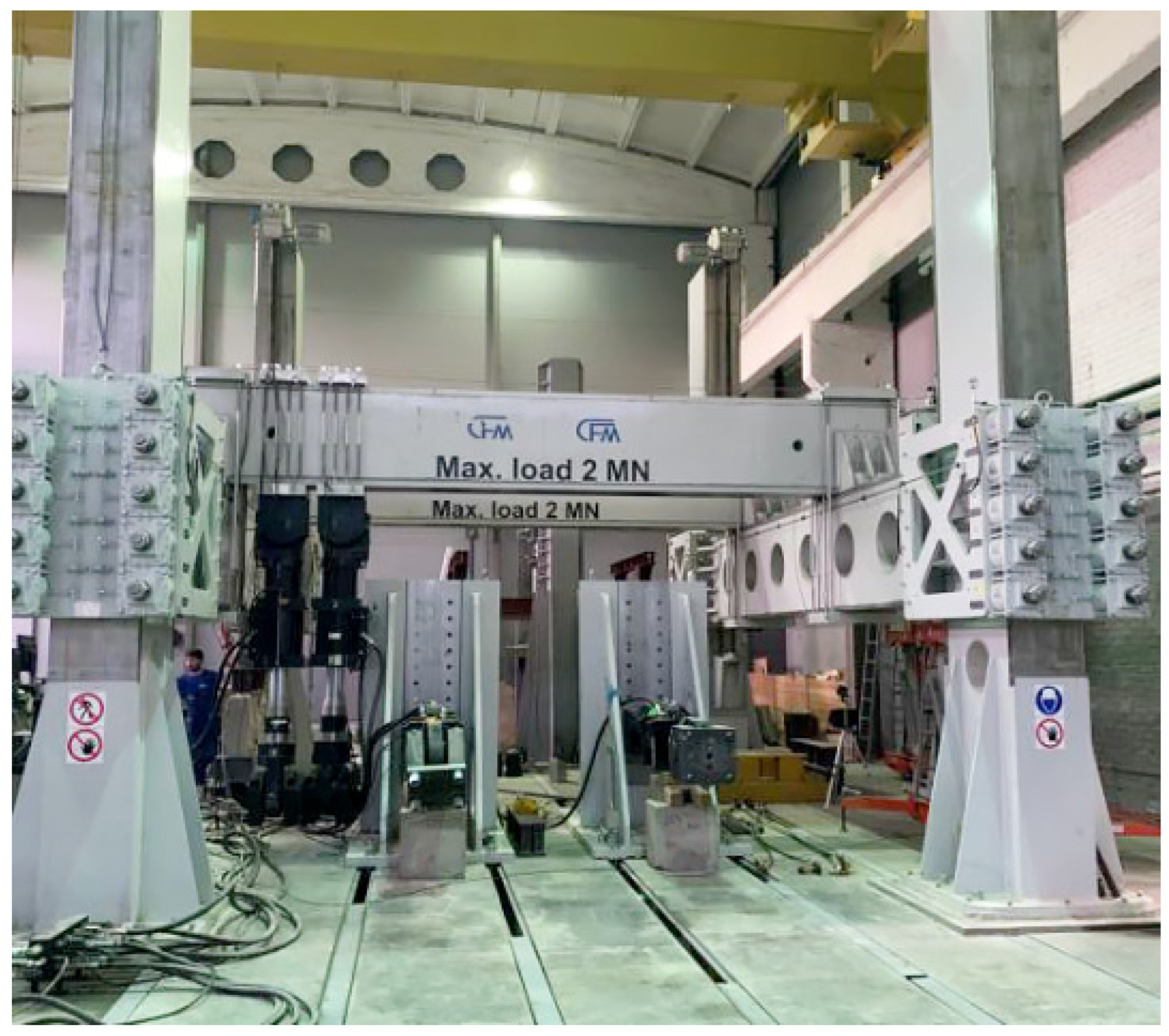
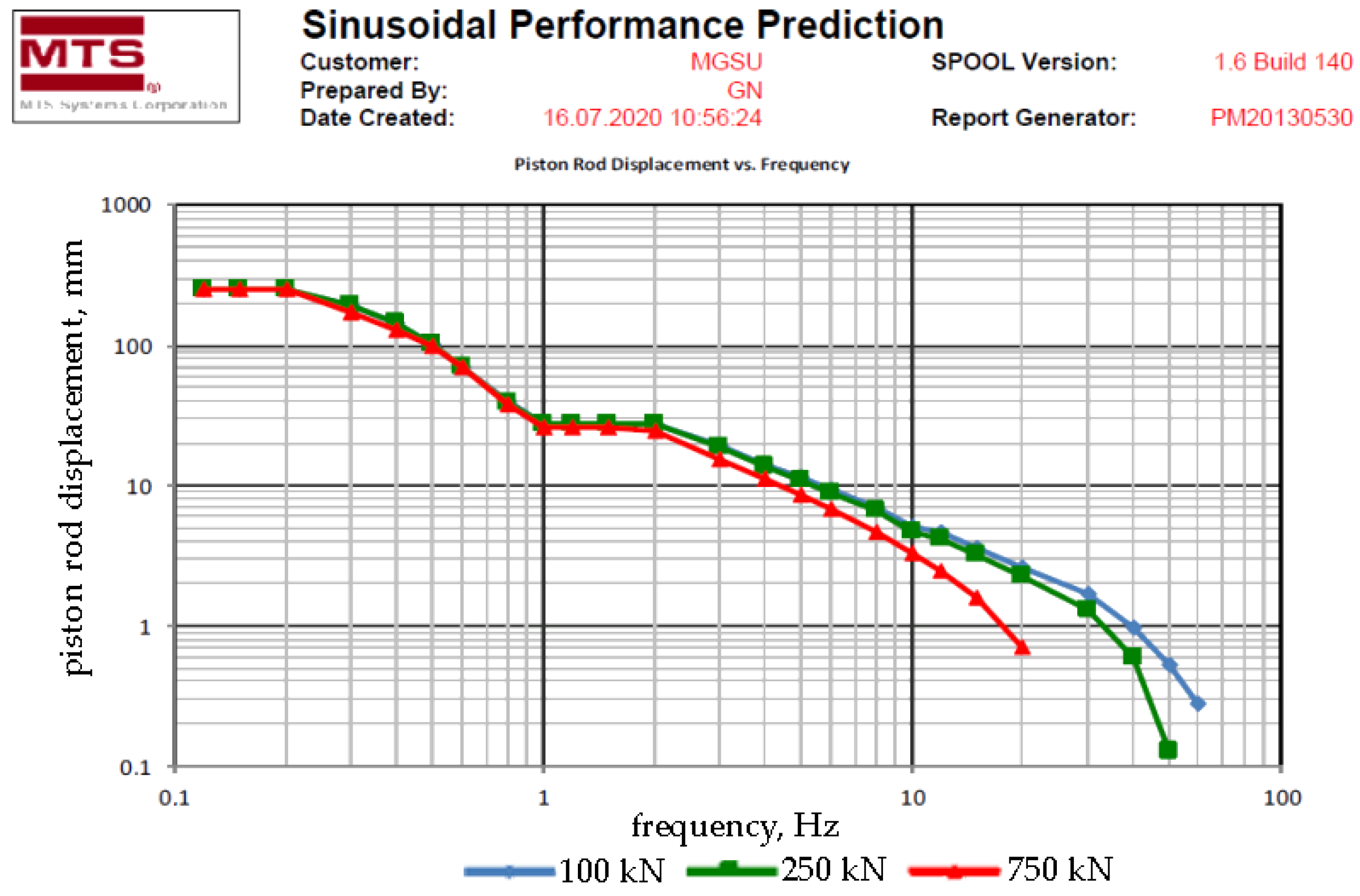
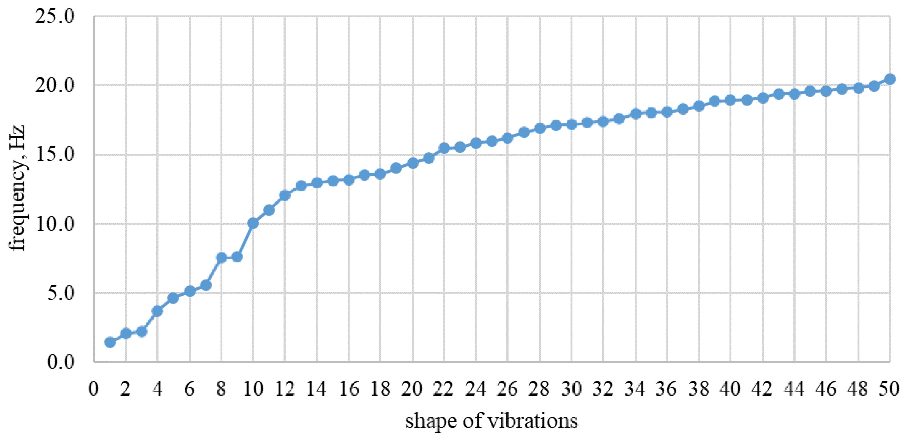
  • MTS-brand hydraulic cylinders (Figure 3), designed to create alternating dynamic action with different acceleration at each stage of loading from 0.2 m/s2 to 4 m/s2, with a frequency from 1 to 50 Hz, displacement amplitude from ±50 to ±250 mm, and maximum force at alternating dynamic action of ±800 kN. The rod displacement was monitored using an LVDT-type displacement sensor. The amplitude–frequency characteristic is presented in Figure 4.
  • Measuring equipment:
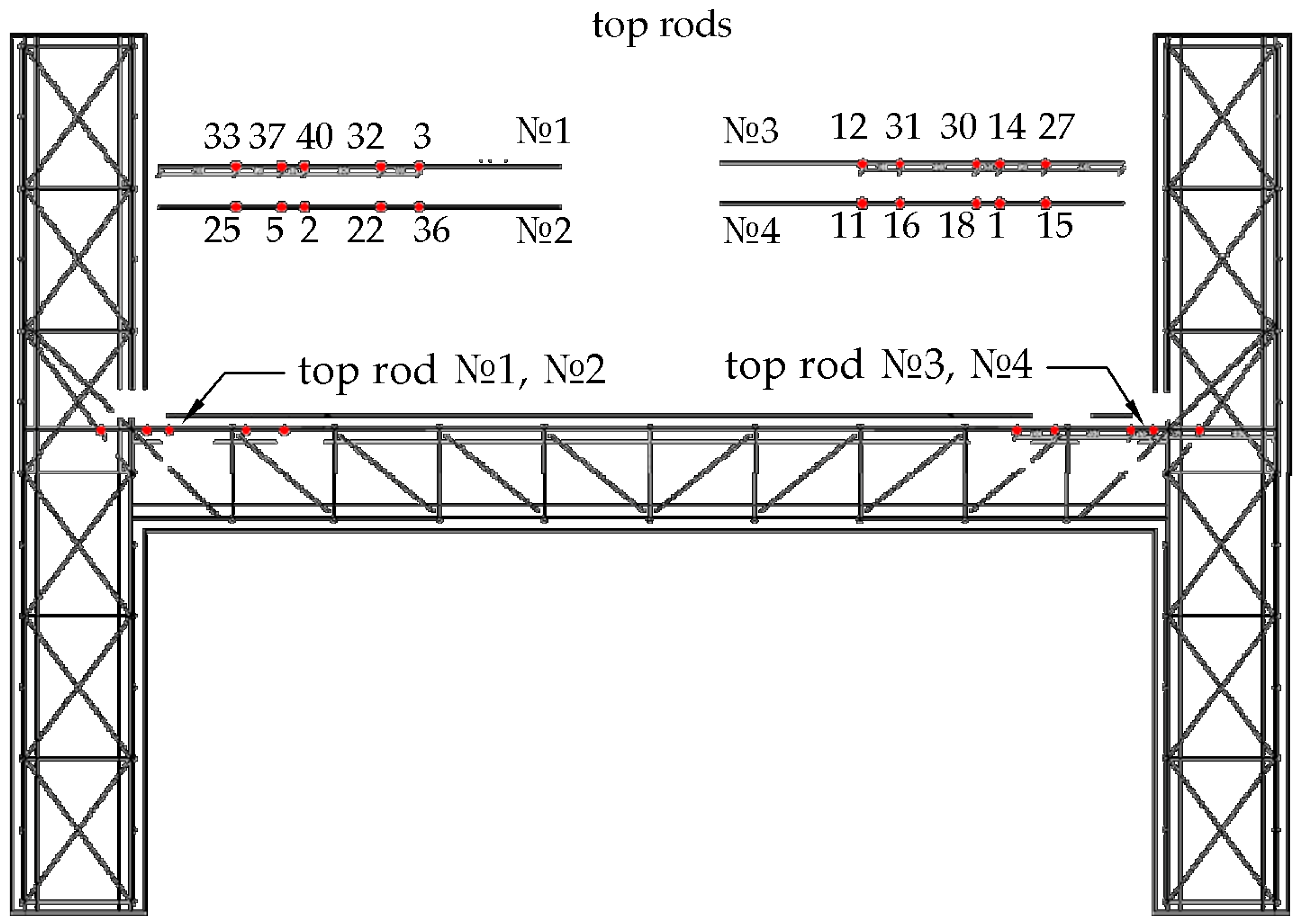
    • FLA and PFL strain gauges were designed to determine relative strains at characteristic points of the structural elements. The grid was made of copper–nickel alloy foil and the substrate was made of an epoxy composition.
    • PCB 352C04 general-purpose single-component accelerometers with integrated ICP electronics.
    • NI PXIe-1082 hardware suite with NI PXI-4496 (for accelerometer data logging) and NI PXIe-4330 (for strain gauge data logging and recording) modules.
    • MTS Flex Test 60 Digital Controller, designed to control dynamic hydraulic cylinders with the ability to monitor and change the parameters of their operation in the process of testing.
The frequencies and amplitudes of the loads applied by the hydraulic cylinders were determined based on the seismic action studies performed. In the modal analysis, the natural frequencies of vibration of the structure and the required value of seismic impacts (Pseism) applied to the structure were determined.
For the experimental studies, 1:2 scale models representing reinforced concrete structures were made (Figure 5), corresponding to typical, characteristic nodes of the existing structural elements of the building of the run-of-river hydroelectric power plant (Figure 6) and the main building of the thermal power plant (Figure 7), including fragments of walls (columns) and floor slabs (transoms).
Concrete of class B35 was used for model construction, which corresponded to the real concrete strength of the structures of the buildings under consideration.
Physical and mechanical characteristics of concrete of class B35:
  • Compressive strength of concrete of class B35:
    • The first group of limit states: Rb = 19.5 MPa;
    • The second group of limit states: Rbn = 25.5 MPa.
  • Tensile strength of concrete of class B35:
    • The first group of limit states: Rbt = 1.30 MPa;
    • The second group of limit states Rbtn = 1.95 MPa.
  • Modulus of deformation of concrete class B35: Eb = 34,500 MPa.
  • Poisson’s ratio of concrete of class B35: γ = 0.2.
The reinforcement of the experimental models (fabricated reinforcement frames are shown in Figure 8) was performed in accordance with the design solution of the structures of the buildings under consideration and the actual characteristics of reinforcement class AIII.
Physical and mechanical characteristics of reinforcement of class AIII:
  • Resistance of reinforcement of class AIII:
    • The first group of limit states: Rs = 365 MPa;
    • The second group of limit states: Rsn = 390 MPa.
  • Modulus of deformation of reinforcement of class AIII: Es = 200,000 MPa.
Carbon Wrap Tape-brand carbon composite tapes and Carbon Wrap Resin-brand thermoactive adhesives (epoxy two-component binders) were used. The suppliers of the composite materials are below:
(a)
Nanotechnological Center of Composites Ltd., Moscow, Russia;
(b)
Jumatex JSC., Moscow, Russia.
This study used Carbon Wrap Tape 600/xxx, wherein 600 is the surface density and xxx (150, 260, 300, 600) is belt width, mm.
Physical and mechanical characteristics of Carbon Wrap Tape:
  • Surface density 600 g/m2;
  • Tape thickness (monolayer) 0.333 mm;
  • Fiber modulus of elasticity not less than 230 GPa;
  • Tensile strength of the fiber is not less than 4900 MPa;
  • The average value of the tensile strength of the tape over a monolayer is not less than 3600 MPa.
The properties of the composite material used for reinforcement were constant. Nowadays, composite materials based on 12 K specification are used, i.e., there are 12,000 carbon fibers in one bundle of composite material tape, so it is practically possible to vary the number of layers and width of the tape. In this study, the number of layers of composite material varied according to the level of seismic impact.
At the reinforcement sections of the experimental model, subjected to characteristic loads arising under seismic action, in order to determine the magnitudes of deformations and the degree of loading (crack formation, failure), strain gauges were installed, the scheme of arrangement of which is shown in Figure 9.
The location of strain gauges on the metal reinforcement and composite reinforcement material of the experimental reinforced concrete model is shown in Figure 10.
A general view of the reinforced concrete model on the stand for the experimental studies is shown in Figure 11.
The design loads on the reinforced concrete model are shown in Figure 12.
On the basis of the spatial model, a modal analysis was performed, as a result of which, the natural frequencies of vibration of the structures were determined. Then, a series of calculations for the dynamic effects of a seismic event were performed for magnitudes 4–10, respectively. As a result of the dynamic calculation of the spatial model, the maximum seismic displacements from corresponding seismic events of magnitude 4–10 were obtained. According to the results of the inverse calculation, the dynamic force leading to these displacements was determined, a graph of which is shown in Figure 13.
The seismic impact on the experimental reinforced concrete model was assumed in the form of an alternating load, a graph of change of which is shown in Figure 14.

3. Results

3.1. Results of Computational Studies

The experience of modeling and the calculations of the stress–strain state of the reinforced concrete structures of thermal and hydroelectric power plants, taking into account the design features, including the frame elements, were considered in the calculation studies of the stress–strain states [41,42,43,44,45].
To illustrate the deformed scheme under seismic action, the fifth form of natural vibrations of the considered fragment of the TPP main building structure is shown in Figure 15.
In the first stage of the computational studies, a modal analysis of the general computational scheme, shown in Figure 15, was performed, on the basis of which, the natural frequencies of vibration of the structures were determined.
The frequencies and shapes of natural vibrations are shown in Figure 16.
The results of the computational studies of the experimental reinforced concrete model without strengthening showed that under seismic action (±13.51 kN)–(±60.83 kN), horizontal displacements of the top of walls (columns) amounted to 1.15–18.68 mm. The formation of cracks in the joints of walls (columns) with the transom occurred under the seismic impact of 25.0 kN. The character of cracking in the non-strengthened reinforced concrete structure obtained by calculation is shown in Figure 17.
The maximum stresses on the metal reinforcement of the slab (transom) in the non-strengthened reinforced concrete structure were σs = 279.35 Mpa, presented in Figure 18.
The results of the computational studies of the above experimental (with cracks) reinforced concrete model, strengthened “after the earthquake” by external reinforcement with composite materials, showed that under seismic impact (±13.51 kN)–(±105.26 kN), horizontal displacements of the top of walls (columns) amounted to 1.15–(13.12–19.45) mm. The maximum stresses on the metal reinforcement of the slab (transom) was σs = 307.05 MPa when external reinforcement made of composite material was included in the work.
The results of the computational studies of the experimental reinforced concrete model, initially strengthened by external reinforcement with composite materials, showed that under seismic impact (±13.51 kN)–(±105.26 kN), the horizontal displacements of the top of the columns amounted to 0.97–15.13 mm. Crack formation at the transom–column interface nodes occurred under a seismic action of 41.92 kN. The maximum stresses on the metal reinforcement of the transom were σs =2 97.72 MPa when external reinforcement from composite material was included in the work.
The results of stress calculations for the metal reinforcement of the slab (transom) for three design variants: without CFRP reinforcement; with cracks and reinforcement “after the earthquake; and initially reinforced (without cracks), are shown in Figure 19.
The results of stress calculations for the composite reinforcement material are shown in Figure 20.
From Figure 20, it follows that the stresses on the composite material increased systematically in accordance with the increase in seismic impact.
The horizontal displacements of the upper parts of the walls (columns) are shown in Figure 21.

3.2. Experimental Results

The cracking character at the stage of failure of the reinforced concrete model without CFRP reinforcement is shown in Figure 22. The cracking pattern correlated reasonably well with the design data (Figure 17).
The stresses on the metal reinforcement of the slab (transom) changed depending on the seismic effect and the distance from the wall (column) face, as shown in Figure 23 and Figure 24.
From Figure 24, it follows that the maximum tensile stresses on the metal reinforcement occurred in the area of the junction of the slab (transom) with the wall (column), which agreed with the results of the calculation studies, shown in Figure 18.
As an example, the data for one metal rod of a slab (transom) are presented, since the other rods recorded close results.
From Figure 24, it can be seen that under seismic action of about 60 kN, the experimental reinforced concrete structure failed to reach the yield strength of the reinforcing bars, which correlated with the design values shown in Figure 17.
It should be noted that in accordance with the conducted research (Figure 13), the seismic impact of 60 kN corresponded to magnitude 7.5 (MSK-64).
According to the results of the experiment, the actual cracking started at a seismic impact of 25 kN, which corresponded to magnitude 6.0 (MSK-64) and correlated with the calculated values; the character of cracking is shown in Figure 17.
Thus, it follows from the results of the experiment that the investigated reinforced concrete structure could withstand a seismic impact of up to magnitude 7.5 (MSK-64), which corresponds to the design requirements at the time of construction.
As shown in the experimental model studies, this structure currently requires strengthening at the maximum normative seismic impact of magnitude 9–10 (MSK-64).
The scheme and parameters for the strengthening of a reinforced concrete model with composite material as an external reinforcement are presented in Figure 25:
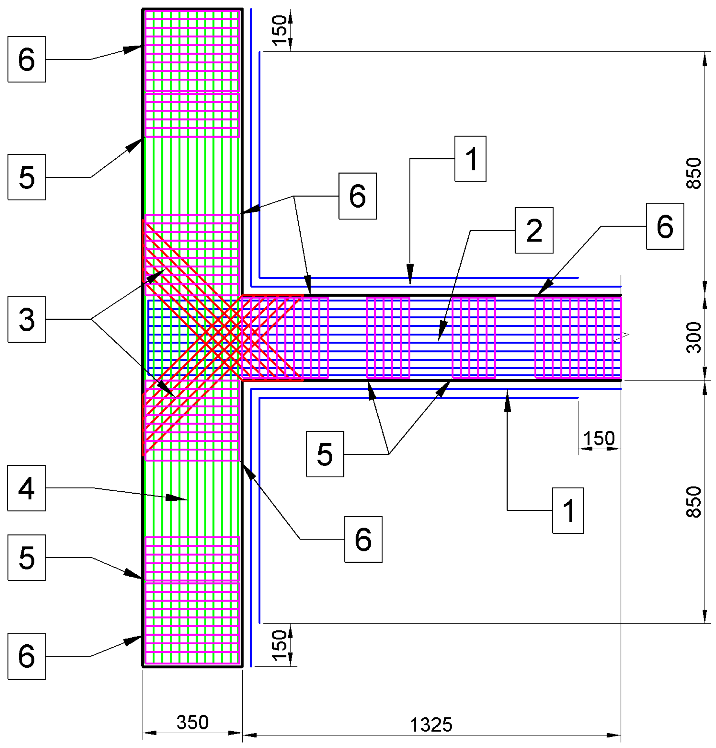
  • With cracking “after the earthquake”, CFRP reinforcement in one layer in the area of the joint connection “wall (column)—floor slab (transom)”;
  • Initially without cracking, CFRP reinforcement in three layers in the area of the joint connection “wall (column)—floor slab (transom)”.
The results of strain gauge measurements of stresses on the metal reinforcement and the composite reinforcement material of the reinforced concrete model are given below:
  • Comparison of experimental results of reinforced concrete structure without strengthening and with strengthening after “earthquake” (Figure 26 and Figure 27);
  • Comparison of experimental results of reinforced concrete structure without strengthening and with strengthening before “earthquake” (Figure 28 and Figure 29).
As a result of computational and experimental studies of reinforced concrete structures strengthened with composite materials under seismic impact, the dependence was obtained (Figure 30).
The magnitude of the increase in seismic resistance in the considered variants was primarily conditioned by the presence/absence of cracking, as well as the time of strengthening (before cracking or after).
For example, the CFRP-unreinforced structure failed earlier than the CFRP-reinforced versions. In a reinforced structure, the overall stiffness was initially reduced after cracking, which led to a reduction in load-bearing capacity. With pre-cracking reinforcement, the initial stiffness of the structure was further increased by compression with a composite material.
From the analysis of the stresses obtained in the experiments on the metal reinforcement and the composite material of the external reinforcement as a function of seismic action, for example, Pseism = 80 kN (Figure 27 and Figure 29), the following results were obtained:
(1)
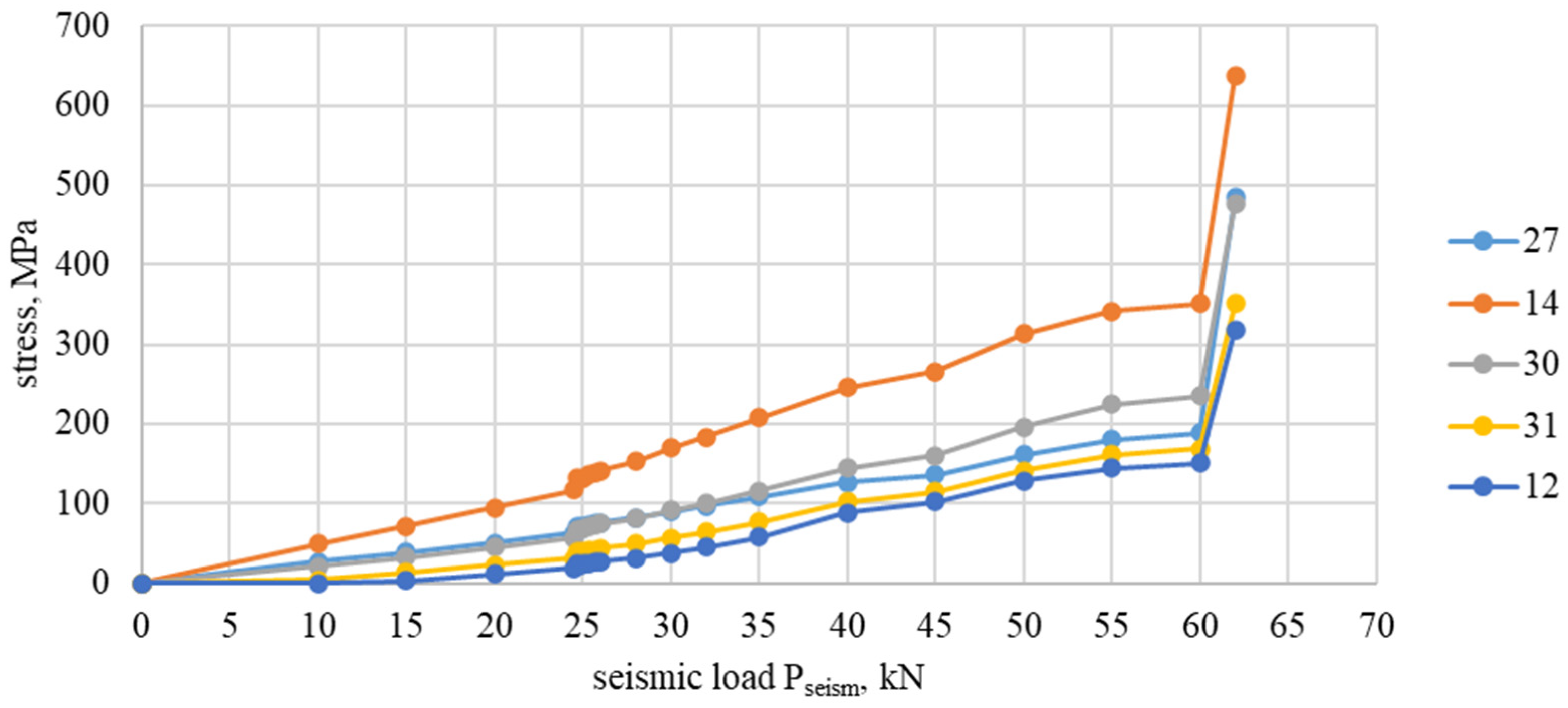
Actual stresses σs = 140 MPa at design resistance of metal reinforcement Rs = 365 MPa, i.e., σs/Rs = 38.4% (Figure 27);
(2)
Actual σf = 380 MPa with the average tensile strength of composite tapes Rf = 3600 MPa, i.e., σf/Rf = 10.6% (Figure 27);
(3)
Actual σf = 290 MPa with σs/Rs = 79.5% and σf/Rf = 8.1% (Figure 29).
These percentages are the result of a difference of almost 10 times between the tensile strength of the composite carbon tapes and the tensile strength of AIII-class metal reinforcement.
An analysis of the experimental results of the reinforced concrete model reinforced with composite materials showed the following:
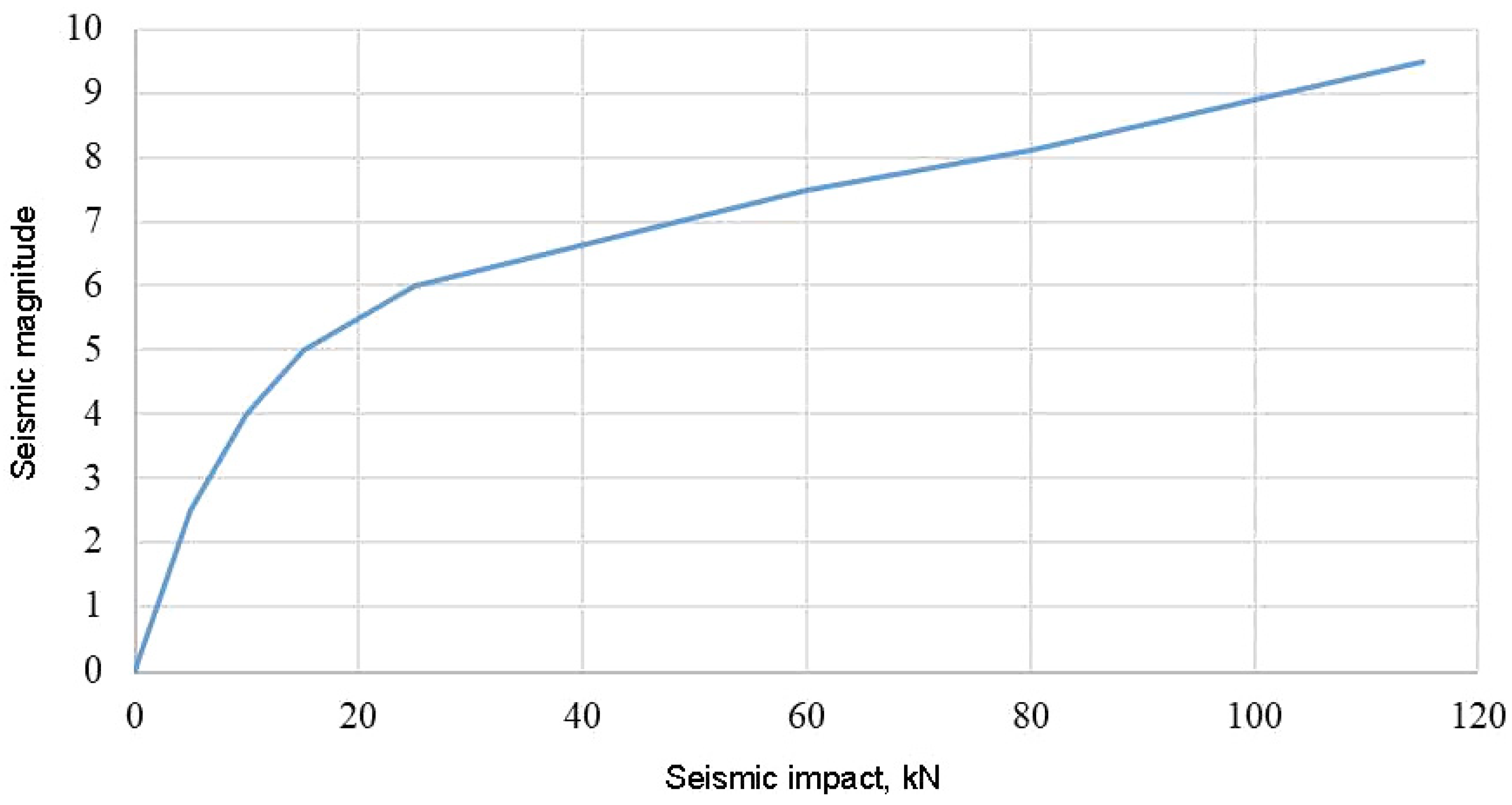
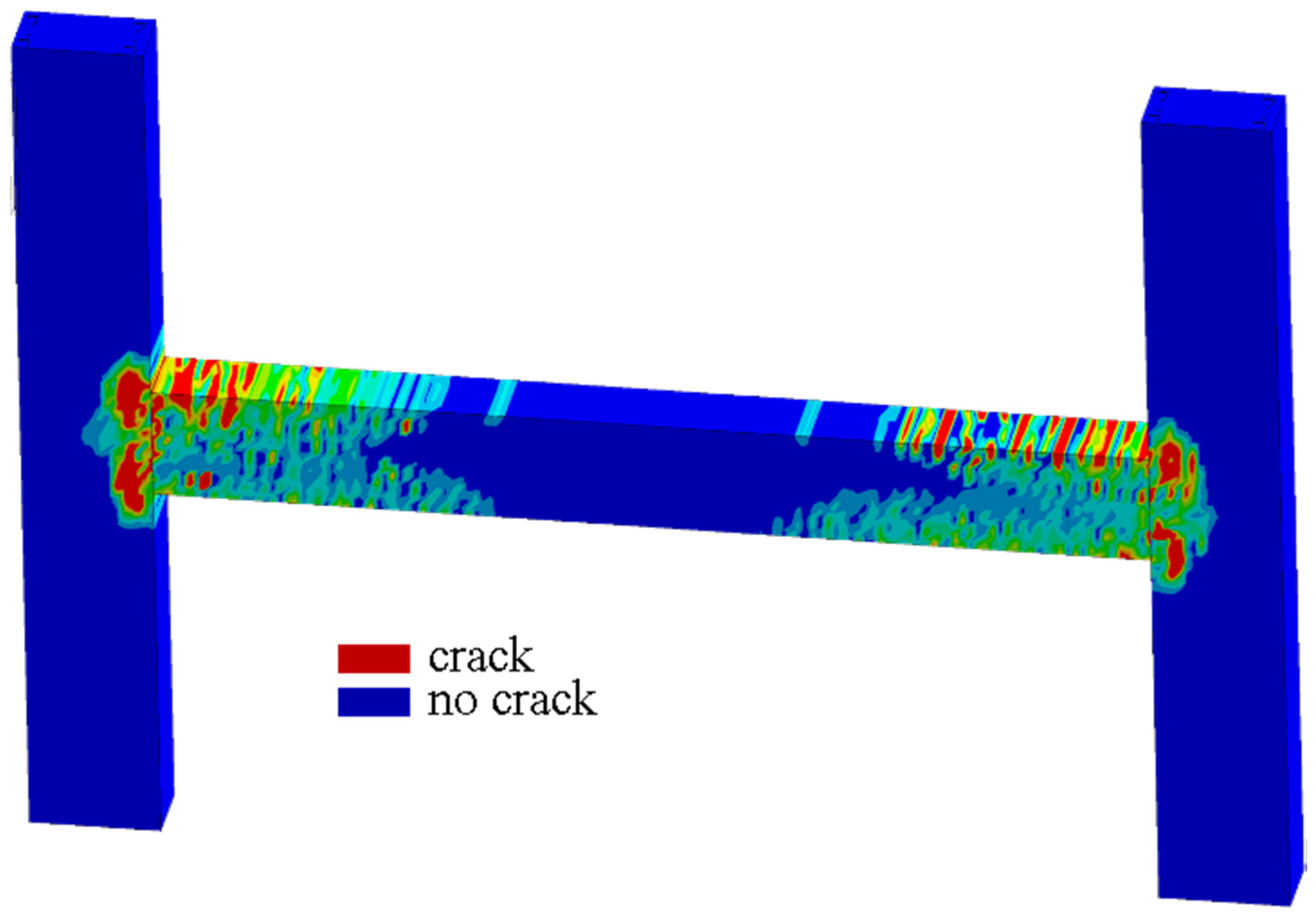
  • Failure of the composite-strengthened reinforced concrete model with cracks “after the earthquake” occurred at a seismic impact of 80 kN, which was 1.33 times higher in comparison with the reinforced concrete model without CFRP reinforcement and corresponded to magnitude 8.1 MSK-64 (Figure 13).
  • Crack formation in the initially composite-strengthened reinforced concrete model in the experiment occurred at a seismic impact of 38 kN, which was higher than that in the non-strengthened reinforced concrete model (25 kN).
  • The initial composite-strengthened reinforced concrete model failed at a seismic impact of 115 kN, which was 1.9 times higher than the non-strengthened reinforced concrete model and corresponded to magnitude 9.5 MSK-64 (Figure 13).
From the measurement results recorded by the strain gauges (mounted on the metal reinforcement and composite reinforcement material), we obtained the following conclusions:
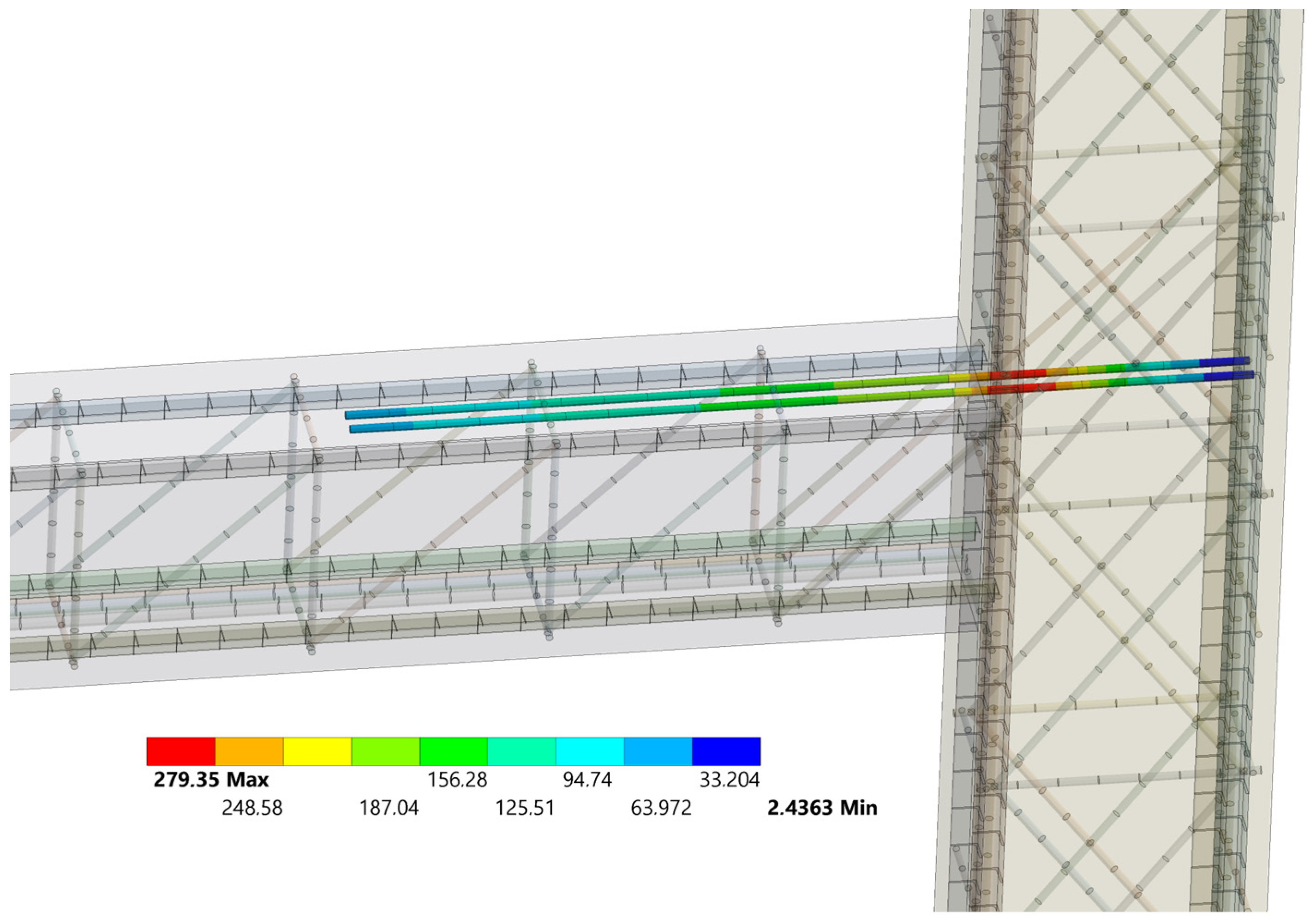
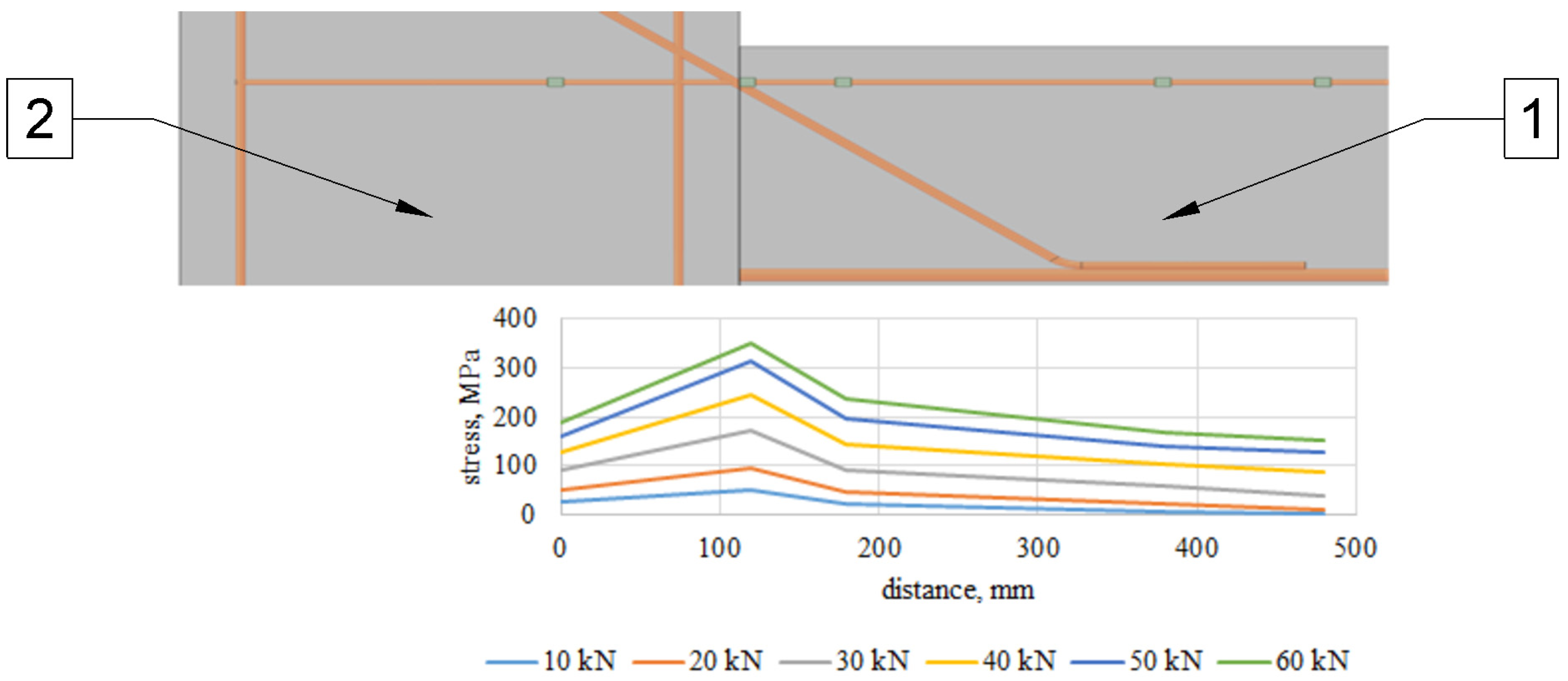
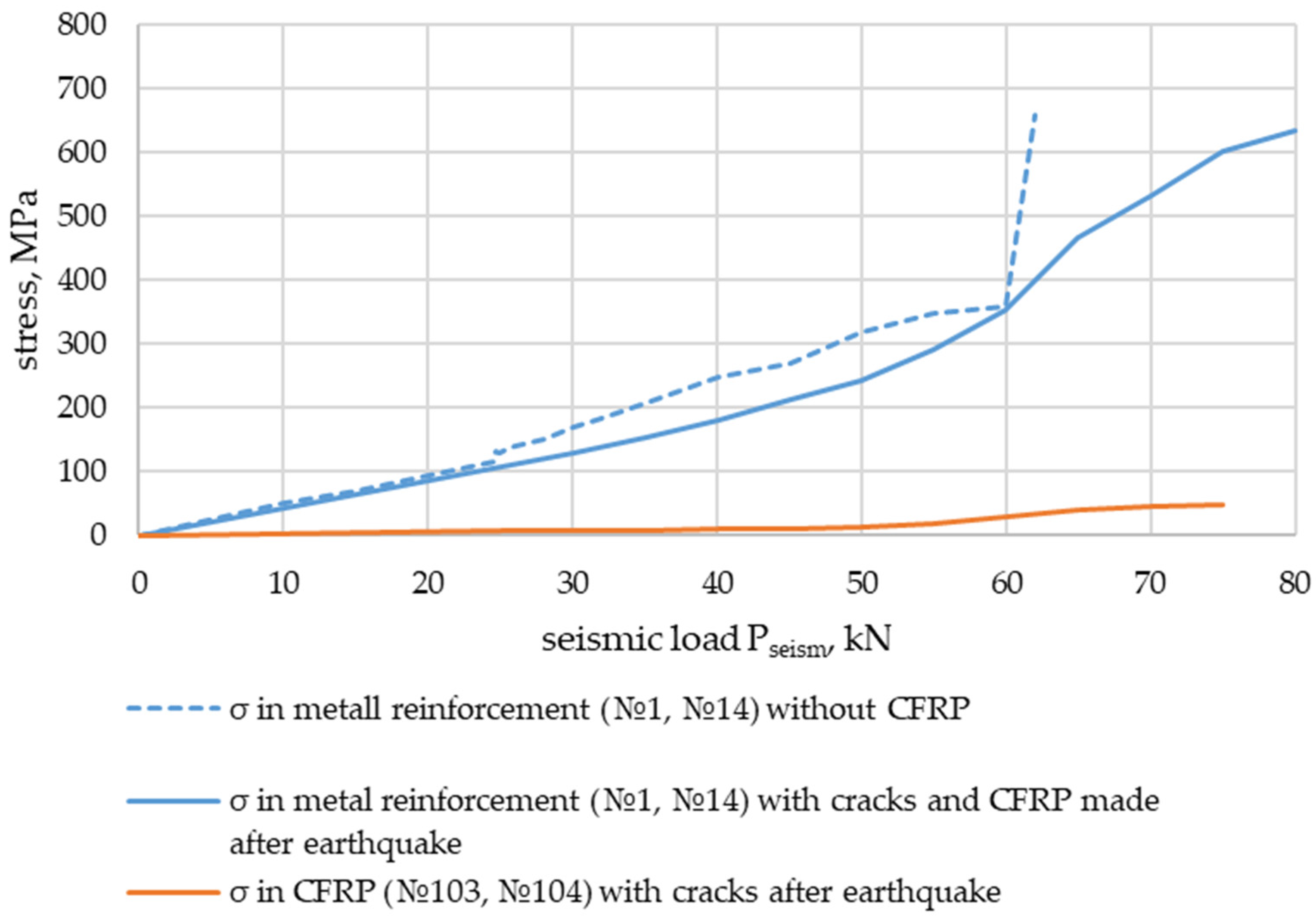
  • In the section along the wall (column) face, the stresses on the metal reinforcement of the reinforced concrete model without CFRP strengthening were greater than those on the reinforced concrete models strengthened with composite materials (Figure 26 and Figure 28), acting as a cage of the butt joint;
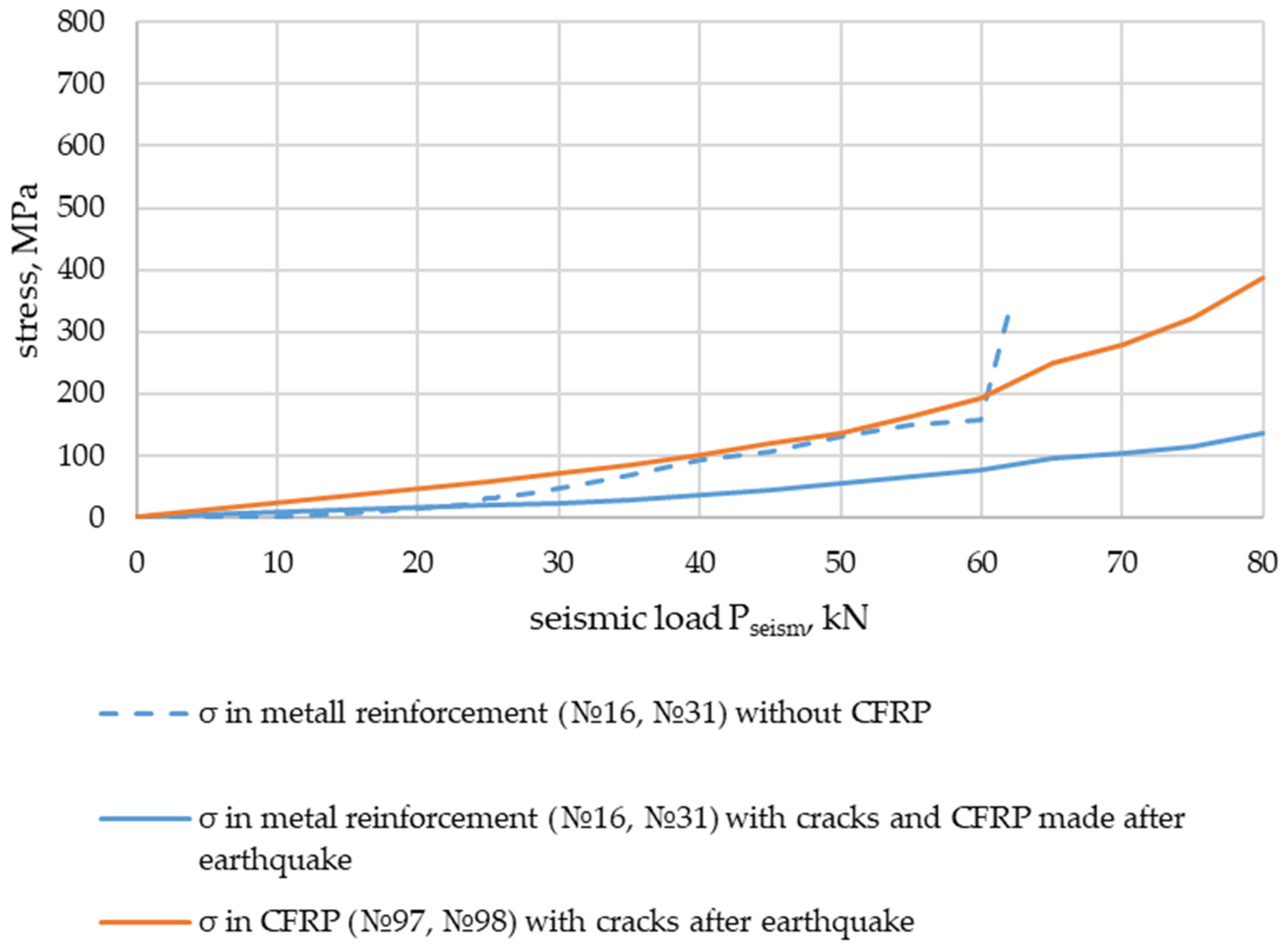
  • In sections along the length of the slab (transom) at a distance of 0.87 h = 260 mm and 1.2 h = 360 mm (where “h” is the height) from the edge of the wall (column), the stresses on the metal reinforcement and composite reinforcement material were close enough, which meant that they worked together (Figure 27 and Figure 29);
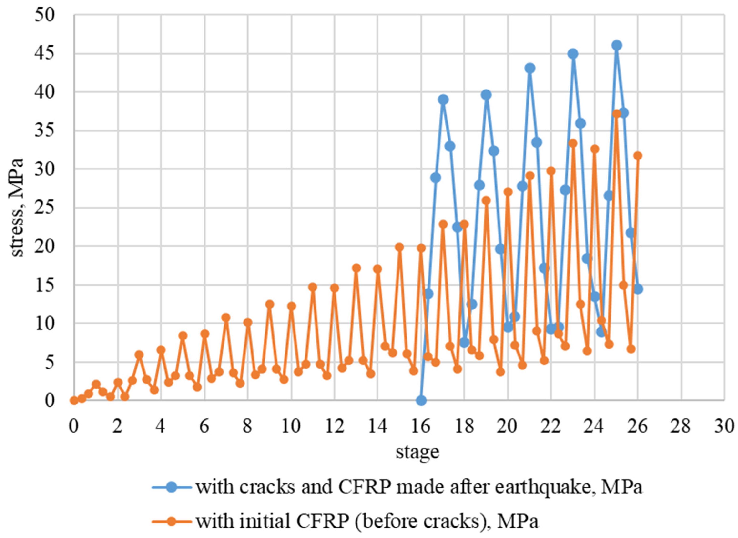
  • Stresses on the metal reinforcement of the reinforced concrete model without reinforcement with composite materials before the seismic impact corresponding to its destruction recorded by strain gauges had values lower than those on the concrete reinforced with composite materials (Figure 27 and Figure 29).
    Estimated calculations showed that the ratio of the cost of strengthening 1 m2 of a reinforced concrete structure with metal/CFRP is approximately equal to 1.6 (taking into account the cost of works directly on the site).

4. Conclusions

  • The conducted calculation and experimental studies of reinforced concrete structures of thermal and hydroelectric power plants aimed at increasing their seismic resistance showed that due to long-term operation and increases in seismic activity, these structures require strengthening.
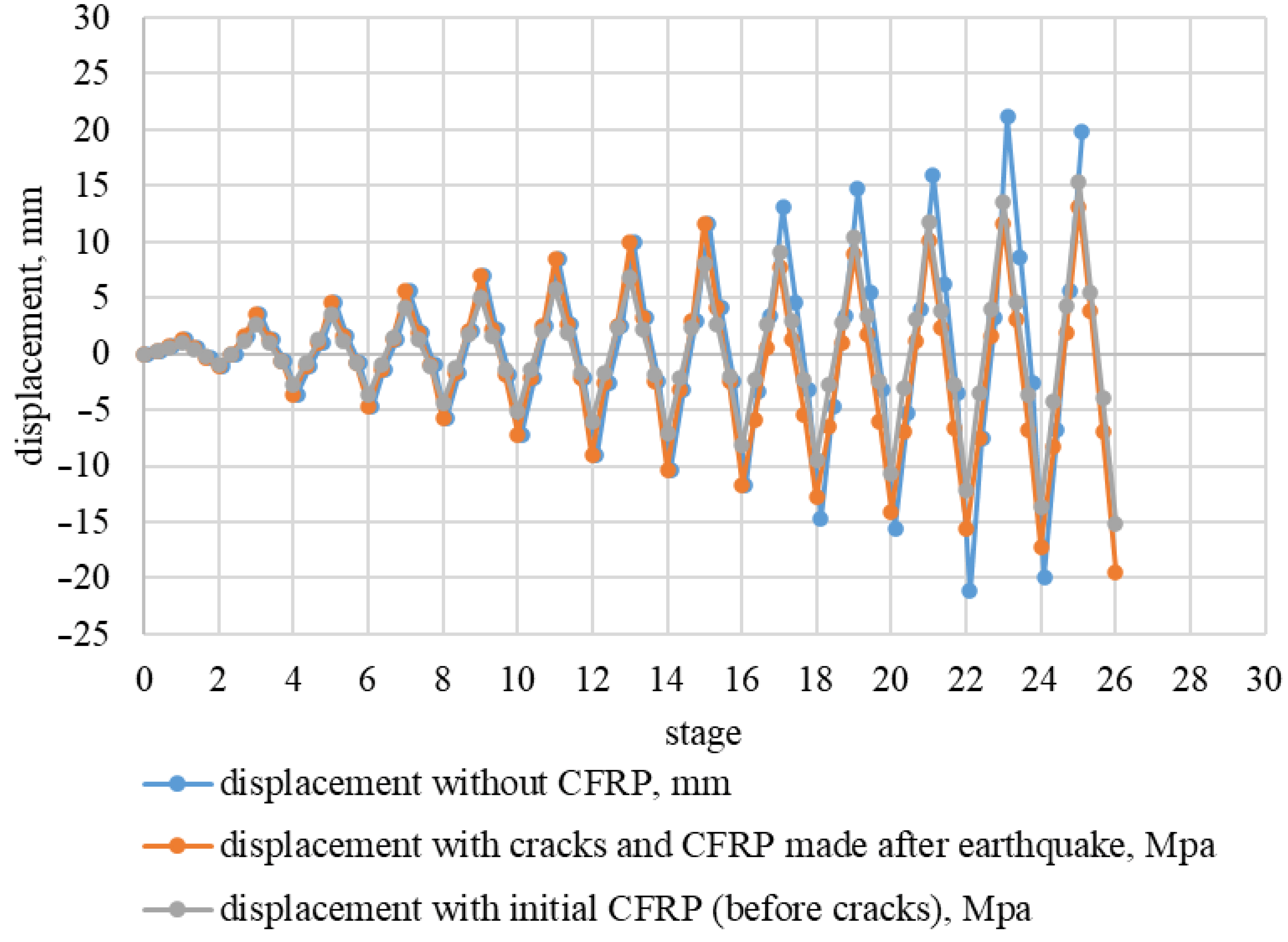
  • In order to increase the seismic resistance of the structures, computational studies were carried out to estimate the parameters to be fixed during experimental studies. The main parameters were crack initiation, horizontal displacements, bearing capacity of reinforced concrete structure, stresses on metal reinforcement, and stresses on composite reinforcement material.
  • Experimental studies showed that in the process of loading the model, there was an inclusion of composite external reinforcement and a redistribution of stresses from the metal reinforcement to the composite material along the length of the slab (transom) in the CFRP-strengthened reinforced concrete model, which increased the stiffness and load-bearing capacity of the structure and significantly increased its seismic resistance.
  • The results of the computational–experimental study showed that cracking of the reinforced concrete structure without CFRP strengthening occurred under a seismic impact of magnitude 6.0 (MSK-64); destruction occurred at magnitude 7.5 (MSK-64). The strengthening of the structure with composite material increased its seismic resistance up to magnitude 9–10 (MSK-64).
  • For practical application by design organizations at the stage of “reconstruction” to improve the seismic resistance of power plants, including after an earthquake, the dependence of the number of layers of composite material in the zone of the joint connection “wall (column)—slab (ledger)” on the acceleration under seismic impact is proposed in Figure 30, in accordance with the nature and parameters of CFRP strengthening, presented in Figure 25.
  • Further computational–experimental studies will be aimed at a more detailed study of the influence of reinforcement schemes and materials on increasing the seismic resistance of structures.

5. Patents

Patent No. RU 220086 U1, 14.07.2023 Rubin O.D., Antonov A.S., Ilyin Y.A., Baklykov I.V., Pisanko A.A. Strengthened metal bearing column.

Author Contributions

Conceptualization, O.R. and E.B.; methodology, O.R. and A.A.; validation, O.R., I.B., O.R., E.B., A.A. and I.B. designed the study, collected the data, wrote the manuscript, and revised the manuscript. All authors have read and agreed to the published version of the manuscript.

Funding

This research was funded by the National Research Moscow State University of Civil Engineering (grant for fundamental and applied scientific research, project no. 39-392/130).

Data Availability Statement

All data, models, or codes that support the findings of this study are available from the corresponding author upon reasonable request.

Conflicts of Interest

There are no conflicts of interest.

References

  1. SP 14.13330.2018 Seismic building design code (OSR-2015) Moscow. 2018; 1–125. (In Russian)
  2. SNiP II-7-81* Seismic building design code (OSR-97) Moscow. 1981; 1–60. (In Russian)
  3. Abdelsattar, D.E.; El-Demerdash, S.H.; Zaki, E.G.; Dhmees, A.S.; Azab, M.A.; Elsaeed, S.M.; Kandil, U.F.; Naguib, H.M. Effect of Polymer Waste Mix Filler on Polymer Concrete Composites. ACS Omega 2023, 8, 39730–39738. [Google Scholar] [CrossRef] [PubMed]
  4. Naguib, H.M.; Zaki, E.G.; Abdelsattar, D.E.; Dhmees, A.S.; Azab, M.A.; Elsaeed, S.M.; Kandil, U.F. Environmentally Friendly Polymer Concrete: Polymer Treatment, Processing, and Investigating Carbon Footprint with Climate Change. ACS Omega 2023, 8, 8804–8814. [Google Scholar] [CrossRef] [PubMed]
  5. Ahmad, J.; Majdi, A.; Babeker Elhag, A.; Deifalla, A.F.; Soomro, M.; Isleem, H.F.; Qaidi, S. A Step towards Sustainable Concrete with Substitution of Plastic Waste in Concrete: Overview on Mechanical, Durability and Microstructure Analysis. Crystals 2022, 12, 944. [Google Scholar] [CrossRef]
  6. Jaf, D.K.I.; Abdulrahman, P.I.; Mohammed, A.S.; Kurda, R.; Qaidi, S.M.A.; Asteris, P.G. Machine learning techniques and multi-scale models to evaluate the impact of silicon dioxide (SiO2) and calcium oxide (CaO) in fly ash on the compressive strength of green concrete. Constr. Build. Mater. 2023, 400, 132604. [Google Scholar] [CrossRef]
  7. Wang, C.; Xiao, J.; Liu, W.; Ma, Z. Unloading and reloading stress-strain relationship of recycled aggregate concrete reinforced with steel/polypropylene fibers under uniaxial low-cycle loadings. Cem. Concr. Compos. 2022, 131, 104597. [Google Scholar] [CrossRef]
  8. Wang, C.; Wu, H.; Li, C. Hysteresis and damping properties of steel and polypropylene fiber reinforced recycled aggregate concrete under uniaxial low-cycle loadings. Constr. Build. Mater. 2022, 319, 126191. [Google Scholar] [CrossRef]
  9. Samarakoon, S.M.S.M.K.; Piatek, B.; De Silva, G.H.M.J.S. Investigation of the Flexural Behavior of Preloaded and Pre-Cracked Reinforced Concrete Beams Strengthened with CFRP Plates. Materials 2023, 16, 22. [Google Scholar] [CrossRef] [PubMed]
  10. Rubin, O.D.; Lisichkin, S.E.; Frolov, K.E. Results of experimental studies of reinforced concrete structures of hydraulic engineering structures reinforced with carbon tapes under the action of bending moment. Stroit. Mech. Eng. Struct. Constr. 2016, 6, 58–63. (In Russian) [Google Scholar]
  11. Rubin, O.D.; Antonov, A.S.; Lisichkin, S.E.; Frolov, K.E.; Lisichkin, A.S. Justification of the solution for reinforcement of reinforced concrete structures after short-term impact loads, by the example of HPP Ayurikin. Constr. Sci. Educ. 2019, 9, 1–6. (In Russian) [Google Scholar]
  12. Uz, M.E.; Guner, Y.; Avci, E. Strengthening of Reinforced Concrete Beams via CFRP Orientation. Buildings 2024, 14, 82. [Google Scholar] [CrossRef]
  13. Wang, H.; Li, C.; Song, S.; Wang, Y.; Meng, Q.; Li, F. Flexural Performance of Cracked Reinforced Concrete Beams Strengthened with Prestressed CFRP Sheets under Repeated Loads. Buildings 2023, 13, 2115. [Google Scholar] [CrossRef]
  14. Al-Khreisat, A.; Abdel-Jaber, M.; Ashteyat, A. Shear Strengthening and Repairing of Reinforced Concrete Deep Beams Damaged by Heat Using NSM-CFRP Ropes. Fibers 2023, 11, 35. [Google Scholar] [CrossRef]
  15. Koutas, L.; Bousias, S.; Triantafillou, T. Seismic strengthening of masonry-infilled RC frames with TRM: Experimental study. J. Compos. Constr. 2015, 19, 04014048. [Google Scholar] [CrossRef]
  16. Facconi, L.; Minelli, F.; Giuriani, E. Response of infilled RC frames retrofitted with a cementitious fiber-mesh reinforced coating in moderate seismicity areas. Constr. Build. Mater. 2018, 160, 574–587. [Google Scholar] [CrossRef]
  17. Matteis, G.; Formisano, A.; Mazzolani, F. An innovative methodology for seismic retrofitting of existing RC buildings by metal shear panels. Earthq. Eng. Struct. Dyn. 2009, 38, 69–78. [Google Scholar] [CrossRef]
  18. Cao, X.-Y.; Wu, G.; Ju, J.-W.W. Seismic performance improvement of existing RCFs using external PT-PBSPC frame sub-structures: Experimental verification and numerical investigation. J. Build. Eng. 2022, 46, 103649. [Google Scholar] [CrossRef]
  19. Valente, M.; Milani, G. Alternative retrofitting strategies to prevent the failure of an under designed reinforced concrete frame. Eng. Fail. Anal. 2018, 89, 271–285. [Google Scholar] [CrossRef]
  20. Valente, M.; Milani, G. An under-designed RC frame: Seismic assessment through displacement based approach and possible refurbishment with FRP strips and RC jacketing. AIP Conf. Proc. 2017, 1863, 450018. [Google Scholar]
  21. Hu, B.; Lv, H.-L.; Kundu, T. Experimental study on seismic behavior of reinforced concrete frames in primary and middle schools with different strengthening methods. Constr. Build. Mater. 2019, 217, 473–486. [Google Scholar] [CrossRef]
  22. Ye, L.P.; Zhang, K.; Zhao, S.H.; Feng, P. Experimental study on seismic strengthening of RC columns with wrapped CFRP sheets. Constr. Build. Mater. 2003, 17, 499–506. [Google Scholar] [CrossRef]
  23. Ghobarah, A.; Said, A. Shear strengthening of beam-column joints. Eng. Struct. 2002, 24, 881–888. [Google Scholar] [CrossRef]
  24. Cao, X.-Y.; Shi, J.; Xu, J.-G.; Ji, E.; She, Y.; Wang, Z. The combined influence of bond-slip and joint-shear in the seismic upgrading via externally-attached BFRP-bar reinforced precast sub-frames. J. Build. Eng. 2023, 80, 107984. [Google Scholar] [CrossRef]
  25. Duong, K.V.; Sheikh, S.A.; Vecchio, F.J. Seismic behavior of shear-critical reinforced concrete frames: Experimental investigation. ACI Struct. J. 2007, 104, 304–313. [Google Scholar]
  26. El-Sokkary, H.; Galal, K. Analytical investigation of the seismic performance of RC frames rehabilitated using different rehabilitation techniques. Eng. Struct. 2009, 31, 1955–1966. [Google Scholar] [CrossRef]
  27. Ali, O.; Bigaud, D.; Riahi, H. Seismic performance of reinforced concrete frame structures strengthened with FRP laminates using a reliability-based advanced approach. Compos. Part B Eng. 2018, 139, 238–248. [Google Scholar] [CrossRef]
  28. Rousakis, T.C.; Anagnostou, E.; Fanaradelli, T.D. Advanced composite retrofit of RC columns and frames with prior damage-Pseudodynamic finite element analyses and design approaches. Fibers 2021, 9, 56. [Google Scholar] [CrossRef]
  29. Fanaradelli, T.D.; Rousakis, T.C.; Karabinis, A. Reinforced concrete columns of square and rectangular section confined with FRP-Prediction of stress and strain at failure. Compos. Part B Eng. 2019, 174, 107046. [Google Scholar] [CrossRef]
  30. Fanaradelli, T.D.; Rousakis, T.C. 3D finite element pseudo dynamic analysis of deficient rectangular columns confined with fiber reinforced polymers under axial compression. Polymers 2020, 12, 2546. [Google Scholar] [CrossRef] [PubMed]
  31. Fanaradelli, T.D.; Rousakis, T.C. Prediction of ultimate strain for rectangular reinforced concrete columns confined with fiber reinforced polymers under cyclic axial compression. Polymers 2020, 12, 2691. [Google Scholar] [CrossRef] [PubMed]
  32. Muslum, M.M.; Fatih, K. Structural Performance of reinforced concrete (RC) moment frame connections strengthened using FRP composite jackets. Arab. J. Sci. Eng. 2021, 46, 10975–10992. [Google Scholar] [CrossRef]
  33. Wang, Y.; Chen, W.; Li, D.; Xu, H.; Zhang, F.; Guo, X. Experimental and Numerical Investigations of the Seismic Performance of Reinforced Concrete Frames Strengthened with CFRP Sheets. Buildings 2023, 13, 2195. [Google Scholar] [CrossRef]
  34. Cornell, C.A. Engineering seismic risk analysis. Bull. Seism. Soc. Am. 1968, 58, 1583–1606. [Google Scholar] [CrossRef]
  35. Aguilar-Meléndez, A.; Ordaz-Schroeder, M.G.; De la Puente, J.; González-Rocha, S.N.; Rodríguez-Lozoya, H.E.; Córdova-Ceballos, A.; García-Elías, A.; Calderón-Ramón, C.; Escalante-Martínez, J.E.; Laguna-Camacho, J.R.; et al. Development and Validation of Software CRISIS to Perform Probabilistic Seismic Hazard Assessment with Emphasis on the Recent CRISIS2015. Comput. Sist. 2017, 21, 67–90. [Google Scholar] [CrossRef]
  36. Grünthal, G.; Stromeyer, D.; Bosse, C.; Cotton, F.; Bindi, D. The probabilistic seismic hazard assessment of Germany—Version 2016, considering the range of epistemic uncertainties and aleatory variability. Bull. Earthq. Eng. 2018, 16, 4339–4395. [Google Scholar] [CrossRef]
  37. Villani, M.; Faccioli, E.; Ordaz, M.; Stupazzini, M. High-Resolution Seismic Hazard Analysis in a Complex Geological Configuration: The Case of the Sulmona Basin in Central. Earthq. Spectra 2014, 30, 1801–1824. [Google Scholar] [CrossRef]
  38. Akkar, S.; Sandikkaya, M.A.; Bommer, J.J. Empirical Ground-Motion Models for Point–and Extended-Source Crustal Earthquake Scenarios in Europe and the Middle East. Bull. Earthq. Eng. 2014, 12, 359–387. [Google Scholar] [CrossRef]
  39. Wells, D.; Coppershmith, K. New empirical relationships among magnitude, repture length, repture width, rupture area and surface displacement. Bull. Seis. Soc. Am. 1994, 84, 974–1002. [Google Scholar] [CrossRef]
  40. CRISIS2015–PSHA. Available online: https://sites.google.com/site/codecrisis2015/home (accessed on 10 June 2024).
  41. Rubin, O.D.; Antonov, A.S.; Ilyin, Y.A.; Baklykov, I.V.; Pisanko, A.A. Reinforced Metal Bearing Column. RU Patent 220086U1, 14 July 2023. [Google Scholar]
  42. Vasiliev, P.I.; Kononov, Y.I.; Chirkov, Y.N. Reinforced Concrete Structures of Hydraulic Engineering Structures; Vishcha Shkola: Kyiv, Ukraine; Donetsk, Ukraine, 1982. (In Russian) [Google Scholar]
  43. Bellendir, E.N.; Rubin, O.D.; Antonov, A.S.; Baklykov, I.V.; Zyuzin, R.S. Ensuring the seismic resistance of operated CHP buildings. In Proceedings of the XXVI International Scientific Conference “Construction the Formation of Living Environment” (FORM-2023) E3S Web of Conferences, Tashkent, Uzbekistan, 26–28 April 2023; Volume 410, pp. 1–9. [Google Scholar] [CrossRef]
  44. Rubin, O.D.; Antonov, A.S.; Karablin, N.P.; Baklykov, I.V. Approach to the state estimation of the steel structures of the main building of the thermal power plant and the reinforcement proposals for the seismic resistance increase. Bull. Eurasian Sci. 2023, 15, 1–13. Available online: https://esj.today/PDF/29AVN323 (accessed on 10 June 2024). (In Russian).
  45. Rubin, O.D.; Antonov, A.S.; Ilyin, Y.u.A.; Baklykov, I.V. Proposals for comprehensive surveys and design studies of structures and constructions of CHPP. Nat. Manag. 2023, 4, 52–58. [Google Scholar] [CrossRef]
Figure 1. Component of the accelerogram for the recurrence period T = 5000 years.
Buildings 14 01971 g001
Figure 2. Reconfigurable power frame.
Buildings 14 01971 g002
Figure 3. MTS-brand hydraulic cylinders.
Buildings 14 01971 g003
Figure 4. Amplitude–frequency characteristic of the hydraulic cylinder.
Buildings 14 01971 g004
Figure 5. Geometric dimensions of reinforced concrete models: ––––––––— boundaries of reinforced concrete model; – – – – – –— boundaries of reinforcement installation. Column dimensions: 2300 × 350 × 200 mm; floor transom dimensions: 2650 × 300 × 200 mm.
Buildings 14 01971 g005
Figure 6. General view of the building of the run-of-river hydroelectric power plant: 1—head bearing wall with overlap.
Buildings 14 01971 g006
Figure 7. General view of the building of the main building of the thermal power plant.: 1—fragment of the structure (columns–transom).
Buildings 14 01971 g007
Figure 8. Reinforcement carcass of reinforced concrete frame model: 1—reinforcement of the wall (columns) model; 2—reinforcement of the floor (transom) model.
Buildings 14 01971 g008
Figure 9. General scheme of strain gauge arrangement on metal reinforcement bars of reinforced concrete model.
Buildings 14 01971 g009
Figure 10. Location of strain gauges on metal reinforcement and composite reinforcement material.
Buildings 14 01971 g010
Figure 11. General view of reinforced concrete model on the test bench: 1—experimental reinforced concrete model reinforced with composite material; 2—seismic impact; 3—static load.
Buildings 14 01971 g011
Figure 12. Calculated loads on the experimental reinforced concrete model: 1—reinforced concrete structure of the model; 2—metal crossbeam (1.61 kN); P—static loads; Pseism—seismic impact.
Buildings 14 01971 g012
Figure 13. Dependence of seismic impact on magnitude for the experimental reinforced concrete model.
Buildings 14 01971 g013
Figure 14. Graph of change of seismic impact on the experimental reinforced concrete model depending on the design stages of loading.
Buildings 14 01971 g014
Figure 15. The 5th form of vibrations at a frequency of 4.67 Hz. Deformed scheme of the reinforced concrete structure of the considered fragment of the main building of a TPP.
Buildings 14 01971 g015
Figure 16. Frequencies and shapes of natural vibrations.
Buildings 14 01971 g016
Figure 17. Cracking pattern in non-strengthened experimental reinforced concrete structure under 25.0 kN of seismic action.
Buildings 14 01971 g017
Figure 18. Stresses on metal reinforcement of slab (transom) in non-strengthened structure under seismic action of 60.83 kN, MPa.
Buildings 14 01971 g018
Figure 19. Stresses on metal reinforcement depending on the stage of loading, MPa.
Buildings 14 01971 g019
Figure 20. Stresses on composite reinforcement material depending on the stage of loading, MPa.
Buildings 14 01971 g020
Figure 21. Horizontal displacements of the upper parts of walls (columns) depending on the loading stage, mm.
Buildings 14 01971 g021
Figure 22. Cracking pattern of experimental reinforced concrete model without CFRP reinforcement.
Buildings 14 01971 g022
Figure 23. Stress diagrams of the reinforcing bar of the slab (transom), depending on the distance from the wall (column) face, Mpa: 1—transom; 2—column.
Buildings 14 01971 g023
Figure 24. Stresses recorded by strain gauges nos. 12, 31, 30, 14, and 27 of the upper reinforcing bar no. 3 of the slab (transom) as a function of seismic action.
Buildings 14 01971 g024
Figure 25. Technological scheme of the strengthening of reinforced concrete model fragment: 1—Tape 600/150, 2 layers; 2—Tape 600/260, 2 layers; 3—closed clamp Tape 600/300, 3 layers (magnitude 9.5), 1 layer (magnitude 8.1); 4—Tape 600/300, 3 layers; 5—closed clamp Tape 600/150, 1 layer; 6—closed clamp Tape 600/300, 1 layer.
Buildings 14 01971 g025
Figure 26. Section №1 (0 mm from the wall (column)). Stresses on the metal reinforcement and the composite material for strengthening the slab (transom).
Buildings 14 01971 g026
Figure 27. Section №3 (360 mm from the wall (column)). Stresses on the metal reinforcement and the composite material for strengthening the slab (transom).
Buildings 14 01971 g027
Figure 28. Section №1 (0 mm from the wall (column)). Stresses on the metal reinforcement and the composite material for strengthening the slab (transom).
Buildings 14 01971 g028
Figure 29. Section №3 (360 mm from the wall (column)). Stresses on the metal reinforcement and the composite material for strengthening the slab (transom).
Buildings 14 01971 g029
Figure 30. Dependence of the number of layers of composite material in the zone of joint connection “wall (column)—slab (transom)” on the acceleration under seismic action.
Buildings 14 01971 g030
Table 1. Quantitative assessment of initial seismic intensity.
Repeatability PeriodPeak
Acceleration
(PGA), g
Spectral AccelerationsMagnitude (MSK-64)
SA (T = 0.2 s), gSA (T = 0.5 s), gSA (T = 1.0 s), g
500 years0.0960.2220.1290.0646.9
1000 years0.1460.3390.1970.1017.5
5000 years0.3100.7300.4340.2338.6
Disclaimer/Publisher’s Note: The statements, opinions and data contained in all publications are solely those of the individual author(s) and contributor(s) and not of MDPI and/or the editor(s). MDPI and/or the editor(s) disclaim responsibility for any injury to people or property resulting from any ideas, methods, instructions or products referred to in the content.

