Abstract
The alkali–silica reaction significantly impacts the durability of reinforced concrete structures. This paper aims to investigate the structural expansion properties of reinforced concrete beams under different partial alkali–silica reactions. Alkali–silica reaction tests were conducted on four reinforced concrete beams, focusing on immersion depth and NaOH solution position as key parameters. Subsequently, the spatial and temporal distribution characteristics of the beam expansion rate were analyzed. Results indicate notable variations in the expansion’s initiation, rate, and final magnitude at different measurement points on the concrete beam, depending on the soaking positions and depths used. The expansion rate was higher in areas directly immersed in the NaOH solution, decreasing near the reinforcement regions. However, strain distribution, along with beam height, satisfied plane-section assumption in the reinforced beam section. Finally, a regional expansion index was established to quantitatively assess the non-uniform damage by alkali aggregates in beams, and the uniaxial restraint mechanism in reinforced concrete structures was also described.
1. Introduction
The alkali–silica reaction (ASR) is a chemical reaction between the alkali in cement and active aggregates, which not only causes concrete expansion, cracking, and even destruction [1], but also has an impact on mechanical properties such as compressive strength [2,3]. Therefore, ASR is an essential factor that affects the durability of concrete [4]. Previous studies have demonstrated significant deterioration in concrete structures, especially those in hydropower projects [5,6,7]. The alkali reaction produces a gel that absorbs water, expands the volume, and creates expansion stress in the concrete. Cracks occur in the structure when the expansion stress exceeds the tensile strength of the concrete. Through cracks, the gel moves to other places such as cement paste, pores, and interfaces, while continuing to exert pressure [8]. As the reaction progresses within different spaces of concrete, both the number and width of cracks increase. These cracks then form a network that impacts the durability of concrete [9].
Previous studies have investigated the degradation of material performance caused by ASR [10,11] during free expansion. Sanchez et al. [12] described the generation and extension of damage caused by ASR under unconfined conditions. Regardless of the aggregate type, the damage caused by ASR varies as the specimen expands. Takahashi [13] confirmed the dimensional dependence of alkali–aggregate translation by testing ASR-induced swelling in mortar bar specimens of different sizes. The results demonstrated that for specimens made from the same material, larger specimens exhibited greater expansion. Pan [14] conducted experiments using four different sizes of coarse aggregate concrete specimens to examine the influence of coarse aggregate size on ASR damage. The tests revealed that larger aggregates resulted in a more significant reduction in mechanical properties for a given rate of ASR expansion.
Most existing studies on ASR are conducted without considering restraints. However, in actual structures, the expansion and cracking induced by ASR can be influenced by various restraint and boundary conditions. Previous studies have investigated the effect of stress on ASR development [15,16]. According to Multon [17], external restraints limit the expansion of the specimen along the restrained direction and transfer it to the unrestrained direction. Morenon [18] described how external stresses influence ASR expansion and cracking. Several studies have shown that restraints can restrict concrete expansion caused by ASR [19].
Reinforcement is the primary internal restraint in reinforced concrete (RC) structures. The reinforcement can alter the generation and propagation of ASR-induced damage [20]. It has been discovered that when RC is elastically restrained in the direction of reinforcement, it induces tensile stress in the reinforcement, thereby primarily restraining the expansion caused by ASR along the direction of reinforcement [1]. Sogbossi [21] indicated that reinforcing steel could reduce the permeability of damaged concrete by limiting crack extension. However, through pull-out testing on accelerated ASR specimens, Li [22] demonstrated that ASR damage would diminish the bonding performance of RC and result in reduced restraint.
Increasing the relative humidity can accelerate the process of ASR, while raising the temperature can speed up the gel formation and expansion caused by ASR [23]. A high alkali content in the pore solution of concrete can also hasten the development of ASR. The addition of sodium hydroxide (NaOH) to concrete can effectively accelerate ASR within the material, and as NaOH is added, there is an increase in both the degree of concrete expansion and cracking [24,25]. Soaking concrete specimens in a NaOH solution under high-temperature conditions can also expedite aggregate ASR [26]. In subsequent experiments, a method was used to accelerate the development of ASR, involving soaking concrete specimens in a high-temperature NaOH solution.
However, a significant amount of research typically analyzes expansive behavior and changes in mechanical properties following ASR reactions at a material level [27,28]. This involves testing standard specimens made from plain concrete without considering how steel reinforcement restrains these reactions [29]. The study of ASR reactions in reinforced concrete structures is still limited to small samples like prisms and cylinders. Based on this limitation, finite element calculations are conducted for both plain and reinforced concrete structures to simulate their mechanical properties during expansion [30,31,32,33,34]. However, this modeling process is complex and cannot be applied universally for simulating all types of reinforced concrete structures. Additionally, this does not account for the impact of non-uniform expansion and the dynamic constraints of steel reinforcement, highlighting certain deficiencies in research on structural-level expansion characteristics caused by alkali reactions. It fails to accurately describe the restraining effect of steel during non-uniform expansion due to environmental factors, and as existing experiments and simulations do not reflect actual engineering scenarios, it is necessary to clarify the expansion characteristics of concrete at the beam scale through long-term monitoring tests on members, and to subsequently analyze the restraining effect of steel bars.
In this paper, four RC beams underwent an accelerated ASR test, with immersion depth and position as experimental variables, which was conducted to investigate the expansion properties of ASR concrete under reinforcement restraints. Based on 34 months’ worth of expansion monitoring data, spatial and temporal distribution mechanisms for the expansion rate in RC beams were analyzed. A regional expansion index was proposed to assess the degree of deterioration in different parts of the beams, and the effect of steel bars on the expansion rate was also studied.
2. Experimental Program
2.1. Materials
The experiment used Ordinary Portland cement (PO 42.5). The mortars had a water/cement ratio (w/c) of 0.49. The active coarse aggregate had a particle size ranging from 5 to 20 mm, and the active fine aggregate had a fineness modulus of 2.4. The quantities of cement, water, sand, stone, and water reducing agent per cubic meter were 440 kg/m3, 200 kg/m3, 443 kg/m3, 1158 kg/m3, and 1.5 kg/m3, respectively. A polycarboxylate-based superplasticizer was utilized to enhance the fluidity of the concrete, which resulted in a slump greater than 15 cm. At a curing age of 28 days, the average cubic compressive strength of the specimen was measured at 49.57 MPa. An HRB400 rebar with an ultimate strength of 600 MPa, yield strength of 400 MPa, and diameter of 14 mm was employed.
The reactivity of the fine and coarse aggregates was evaluated using the accelerated mortar bar test. According to the Specification for Aggregates for Concrete (ASTM C33/C33M-2008) [35], an aggregate is classified as reactive if it exhibits an expansion of 0.20% or greater after a period of 16 days from the time of pouring. This percentage is a critical metric because it can indicate the potential for ASR, which may lead to detrimental effects on the integrity of the concrete over time. Six mortar prisms with dimensions of 25.4 mm × 25.4 mm × 285 mm were cast and stored in a NaOH solution at a temperature of 80 °C and a concentration of 1 mol/L to accelerate the ASR rate; the experimental method is derived from industry standards [26]. As shown in Figure 1, after being immersed for 14 days, both aggregates exhibited swelling greater than 0.10%; therefore, both fine and coarse aggregates were found to be reactive.
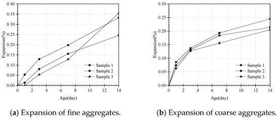
Figure 1.
Test results of the accelerated mortar bar test.
In this study, the sources of coarse and fine aggregates used were consistent. After repeating the aggregate alkali activity test, it was found that there was little difference in the alkali activity of the aggregates. Furthermore, as shown in Figure 1, the expansion of fine aggregates ranged from 0.25% to 0.36%, and the expansion of coarse aggregates ranged from 0.20% to 0.25%. It shows that the difference in alkali activity of the aggregates used is small, and it can be assumed that the distribution of active aggregates in reinforced concrete beams is uniform. This indicates that the difference in alkali activity of the aggregates used is small, and it can be assumed that the distribution of reactive aggregates in reinforced concrete beams is homogeneous.
2.2. Test Specimen
As depicted in Figure 2, tests were conducted on beams with the dimension of 200 mm × 200 mm × 1600 mm. Along the length of the beam, there were two steel bars with a diameter of 14 mm, and the concrete cover was set at 50 mm. The beam casting design is based on experiments conducted by Hayashida [36]. The literature mentions the dimensions of the beam as 200 mm × 200 mm × 1600 mm, with a cover thickness of 50 mm. The expansion of the specimen was continuously monitored throughout the experiment through the utilization of measuring points. As shown in Figure 2, along the height of the beam, measurement points were positioned at depths of 0 mm (Bx-1), 25 mm (Bx-2), 75 mm (Bx-3), 125 mm (Bx-4), 175 mm (Bx-5), and, finally, at a depth of exactly 200 mm (Bx-6). Where x represents the number of the beam, considering that 4 sets of immersion tests were set up in the study, x is equal to 1, 2, 3, and 4, respectively. For example, B1-1 denotes the first measurement point of beam number 1. Figure 3 is the real image of the beam during the alkali reaction process. The initial distance between these measurement points was established as being equal to 150 mm. Stainless steel studs were installed at each measurement point to facilitate expansion measurements using a handheld strain gauge. The initial distance between the measurement points was measured prior to placing the specimen in an alkaline solution. Subsequently, the specimen was placed in the test tanks for the ASR acceleration test. The test lasted 34 months, during which expansion measurements were taken monthly. When measuring the expansion rate of concrete beams, the distance between the same measurement points was repeatedly measured three times using a handheld strain gauge, and the obtained distances between the measurement points were substituted into Formula (1) to calculate the expansion rate for each measurement point. The expansion rate of the specimens can be expressed as follows:
where εt is the expansion rate of the specimen, l0 is the initial distance between the measurement points, and lt is the distance between the measurement points with the immersion time of t.
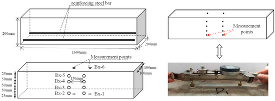
Figure 2.
Schematic of concrete beam expansion measurements.
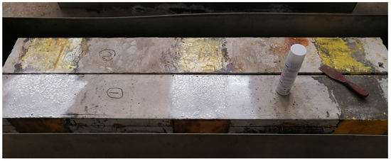
Figure 3.
Actual image of the beam after the alkali reaction.
2.3. ASR Program
After curing for 28 days, all beams were placed in a test chamber containing a 2.8 mol/L NaOH solution to accelerate the development of ASR. As shown in Figure 4, four different immersion methods were selected in this study to obtain different stress states. Taking into account the structural stress characteristics of the beam structure, including tension and compression areas, and considering the extent of expansion changes, measurement points are evenly distributed at symmetrical positions within the structure [36]; as listed in Table 1, Beam 1 (B1) and Beam 2 (B2) were immersed to a depth of 50 mm, while Beams 3 (B3) and 4 (B4) were immersed to a depth of 100 mm. The tension zones of B1 and B3 were soaked areas, while the compression zones of B2 and B4 were soaked areas. Each beam underwent an acceleration period of 1020 days, with the blue area submerged in the NaOH solution and the white area exposed to air. During the test, the height of the solution in the aluminum box was closely monitored, and the solution was periodically checked and replenished. The concentration of NaOH solution in the aluminum box was checked weekly using acid–base titration tests, and adjusted based on the results. If the concentration was too low, additional NaOH solution was added. The entire NaOH solution was replaced once a month to maintain a constant concentration of 2.8 mol/L.
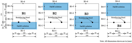
Figure 4.
Schematic of NaOH solution immersion.

Table 1.
Beam specimens.
3. Test Results and Discussion
3.1. ASR Program
3.1.1. Expansion Results in Time Distribution
The relationship between the expansion rate and accelerated ASR time is depicted in Figure 5. The curves illustrate the progression of the expansion rate at each measured point on the beam with time, where Bm (m = 1,2,3,4)-n(n = 1,2,3,4,5,6) represents the nth test point on the mth beam.
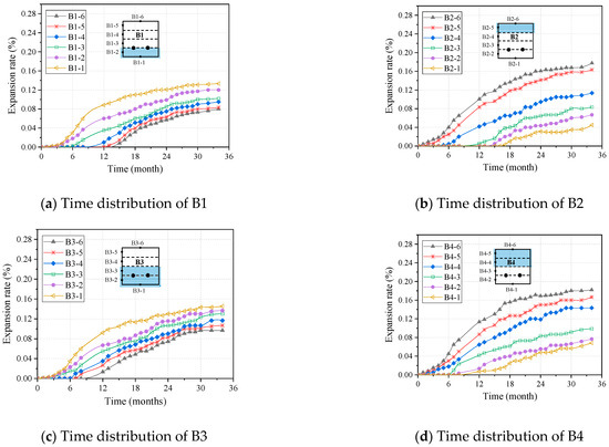
Figure 5.
Time distribution of different beams.
The expansion rate of concrete increased very slowly in the early stage (0–6 months), but sharply increased in the middle stage (6–24 months). In the later stage (24–34 months), when the expansion time reached 24 months, the expansion rate began to slow down and formed a plateau. The development of this expansion can be explained by the ASR reaction mechanism. In the early stages of the ASR reaction, the initial pores of concrete are first filled with ASR gel, thus preventing immediate expansion. Subsequently, water absorption and expansion by aggregates results in micro-cracks on the surface of concrete. After 24 months, the cracks caused by ASR may develop into a state close to being fully open. The formation of such cracks is a common durability issue in concrete that can reduce structural integrity and load-bearing capacity. The surface of the reactive aggregate may be enveloped by ASR gel, which forms from the reaction of alkali metal ions with silicate minerals. The accumulation and encapsulation of this gel may hinder further penetration of NaOH solution into the reactive aggregate, thus slowing down the progress of ASR. Therefore, acro expansion stops as gel supply is not replenished during further progression of the reaction. This phenomenon has also been identified in previous studies [17,37,38,39].
The time of expansion for each measurement point in the early stage is shown in Figure 5. As depicted in Figure 6, the expansion began earlier for B1 and B3, where the lower part was soaked in a NaOH solution. Similarly, for B2 and B4, the expansion initiated earlier when the upper part was soaked in the NaOH solution. In general, there were different start times of expansion for each measuring point. The points immersed in the solution experienced earlier expansion compared to those in the upper drying zone, indicating a noticeable time gradient.
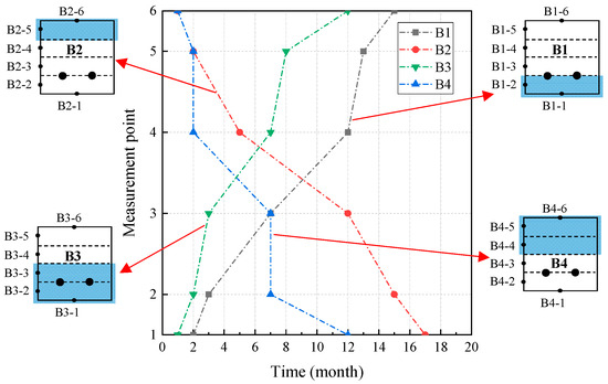
Figure 6.
Expansion start time of different beams.
This phenomenon is caused by the combined influence of water, alkali metal ions, and OH− ions [39,40,41,42]. In areas soaked with the NaOH solution, there is a sufficient water and ion supply to produce more gel products, fill the original pores in concrete, and accelerate the expansion process. However, in areas not immersed in the solution, the alkali–aggregate reaction is mainly accelerated by “wick action” [6], which refers to the evaporation of the solution in the material and its movement towards dry areas. For concrete directly immersed in a sodium hydroxide solution, high pH levels, humidity, and high alkali content could lead to an increased formation of ASR products. Therefore, the test points soaked in the NaOH solution develop ASR more rapidly. However, due to lower ion content and humidity in upper concrete sections, the formation of ASR products was reduced, and the alkali–aggregate reaction was relatively slow.
In the middle stage, the expansion rates of each beam were different. Compared to B1, which had steel bars in the soaking area, B3 had a faster expansion rate than B2 and B4, which had no steel bars in the soaking area. In the later stage, the absolute values of the expansion rates of each beam were also different. When comparing B1 and B2 to different soaking positions for the NaOH solution, their degrees of deterioration differed as well. The expansion rate of B2 without reinforcement in the solution soaking area increased faster at that position compared to B1 with reinforcement in the soaking area. Its maximum expansion rate (0.18%) was higher than that of B1 (0.13%). The same observation was confirmed when comparing B3 and B4 at different soaking positions.
The expansion of ASR is reduced in areas with reinforcement because steel bars generate stress and restrain the expansion, as previously confirmed in [17]. When comparing B1 and B3, which had different immersion depths of the NaOH solution, the degree of deterioration in the two beams also varied. As shown in Figure 5, B3 exhibited a faster expansion rate than B1 when immersed in a solution depth of 100 mm. Additionally, the maximum expansion rate (0.15%) for B3 was higher than that of B1 (0.13%) at an immersion depth of 50 mm. A similar conclusion was drawn by comparing B2 and B4 at different immersion depths.
The experimental results indicate that the sodium hydroxide solution has an impact on expansion. Water acts as a reactant and a transporter for various reactants, which influences the expansion of the reaction [20]. The higher the internal humidity, the faster the expansion occurs. In contrast, Na+ and OH− ions play a significant role in ASR damage [41]. Na+ ions diffuse into the aggregates, leading to the formation of expansion reaction products. Silicate radicals migrate from inside to outside of the aggregate, resulting in silica dissolution. This finding aligns with previous findings [39,43].
3.1.2. Expansion Results in Spatial Distribution
The spatial distributions of the beams are shown in Figure 7, where the abscissa represents the expansion rate, indicating the percentage increase in concrete volume, and the ordinate represents the name of each measuring point. The beam expansion rates at each measuring point in months 0, 4, 8, 12, 16, 20, 24, 28, and 34 are plotted. Among them, B1-1 in B1 exhibits the highest expansion rate. This can be attributed to the effect of reactant concentration. B1-1 was directly immersed in a solution with higher water content and ion concentration. Water acts as a transport agent for various active ingredients by allowing alkali and hydroxyl groups to migrate from the solution into the aggregate and react with silica. Additionally, water and ions directly participate as reactants in the ASR process [6,20,44]. A better supply of water and ions leads to a larger expansion rate at measuring point B1-1. As for B1-2, its expansion was slightly reduced due to restraint from the reinforcement. When ASR generates expansion stress, steel bars produce stress that offsets part of this expansion stress, thereby restraining overall expansion.
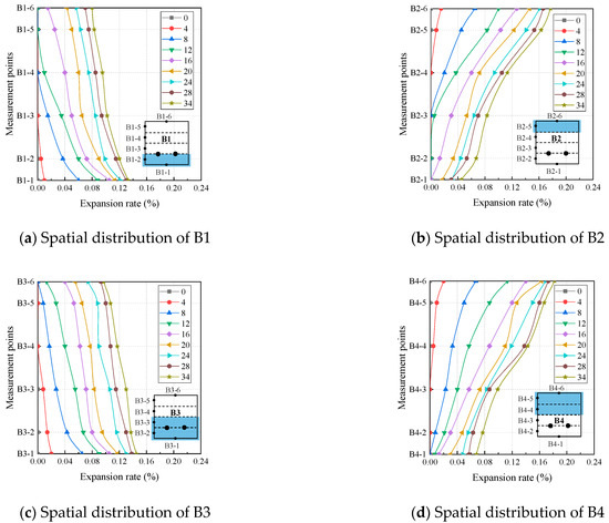
Figure 7.
Spatial distribution of different beam expansion rates.
The expansion rates of measuring points B1-3, B1-4, B1-5, and B1-6 gradually decrease under the combined influence of the NaOH solution and steel bars. On one hand, since these measuring points are not immersed in the solution, water primarily moves from bottom to top through concrete pores and cracks. On the other hand, steel bars also play a specific role in restraining the expansion at these points. It can be observed from the experimental results that in locations where the solution is not soaked, migration of the solution plays a more critical role. The further away from the solution, the lower the swelling rate.
Compared to B1, a similar phenomenon was observed for B2, B3, and B4. The expansion rate in the solution-soaked zone was higher than that in the dry zone. Around the reinforcement, the ASR-induced swelling was significantly reduced, owing to reinforcement restraint. However, by observing the beam strain distribution, the strain distribution across various beam interfaces exhibits an overall linear distribution along the height direction, and its characteristics comply with the assumption of plane sections. Therefore, existing calculation models based on this assumption can be utilized to analyze the deformation and capacity of the structure.
The distribution of the expansion rate was different when comparing B1 and B2, with the same solution depth but different immersion positions. In B1, where the soaking area was in the lower part, there was a larger expansion rate at the bottom, which gradually decreased towards the top. On the other hand, in B2 where the soaking area was in the upper part, there was a larger expansion rate at the top which gradually decreased towards the bottom. The distribution of expansion rates showed a clear correlation with the position of immersion solution. Comparing B3 and B4 with a soaking depth of 100 mm but different immersion positions yielded similar conclusions.
Compared to B1 with an immersion depth of 50 mm, beam B2 with an immersion depth of 100 mm exhibited a higher expansion rate at the same position. Therefore, there is a clear correlation between the degree of deterioration in these beams and their immersion depths. Greater immersion depths result in more severe degrees of deterioration for these beams. When comparing B2 and B4, both having upper parts as immersed areas but at different depths, similar conclusions can be drawn.
3.2. ASR-Induced Cracks
The crack in the specimen was examined using a magnifying glass. Subsequently, a diagram illustrating the distribution of cracks was generated. Within the beam structure, S1 represents the top face, S2 and S3 denote the side faces, and S4 corresponds to the bottom face. Figure 8 provides an overview of the specific components and areas that require description, as well as highlights the observed crack distribution.
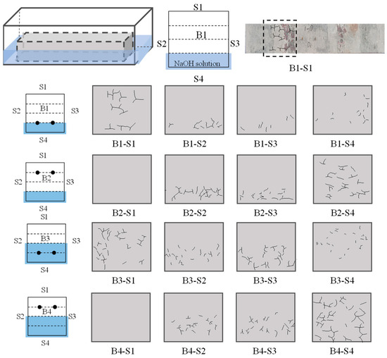
Figure 8.
Cracking of beams.
It is widely acknowledged that ASR induces the formation of gel, which absorbs water and expands, resulting in the generation of internal stresses. When these stresses exceed the tensile strength of concrete, structural cracking occurs [43,45,46]. Figure 8 illustrates the distribution of cracks on all four surfaces of each beam. Upon examining the top surface (S1) and bottom surface (S4) of each beam, it was observed that steel bars impede the propagation of expansion cracks. Specifically for S1, reinforcement provided by B2 and B4 restricts crack extension within the concrete matrix [20]. Notably, no significant cracks were observed in B2-S1 and B4-S1.
Similarly, the presence of steel restraint in B1-S4 and B3-S4 results in a reduced number of cracks for S4. Upon examining the side surfaces (S2, S3) of each beam, it was observed that regions with higher humidity exhibited more cracks. All cracks were found to be distributed below the soaking surface of the solution. Moreover, relatively dense cracking was observed in B3 and B4 with greater solution depths. This observation aligns with the established spatial distribution law of beam expansion, and highlights the correlation between crack formation and expansion rate. The accelerated ASR in concrete, after being soaked in a solution, exacerbates the development of crack patterns and distribution. The density of the crack distribution can be preliminarily explored to assess the state of concrete damage. The presence of cracks weakens the load-bearing capacity of the concrete, and harmful substances can further accelerate damage to the concrete through these cracks. Therefore, they have a negative impact on the mechanical properties and durability of the beam. Additionally, fewer cracks occur near areas close to the steel bar, reflecting the restraining effect of the steel bar on crack development, which helps prevent further deterioration of the concrete structure.
3.3. Restraint Mechanism of Reinforcement under Non-Uniform Damage
3.3.1. Regional Expansion Index of Reinforced Concrete Beams
To quantify the non-uniform degree of damage in beams caused by alkali aggregates, a regional expansion index αt (Equation (2)) was defined, as depicted in Figure 9.
where st represents the cross-sectional area at time t when immersed in the NaOH solution for a duration of t months, s0 denotes the initial cross-sectional area, lt − l0 signifies the measured expansion, and h corresponds to the vertical height of the beam. The term st − s0 can be obtained by integrating the curve representing the rate of expansion. The higher the regional expansion index of an RC beam, the more severe the ASR reaction in that area, resulting in greater expansion damage. Conversely, a smaller regional expansion index of an RC beam leads to a less severe ASR reaction and lower expansion damage.
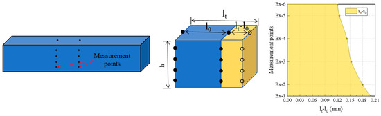
Figure 9.
A schematic of the regional expansion index.
The regional expansion index proposed in this paper can quantitatively assess the damage caused by ASR to structures. By using this parameter as a quantitative indicator, the extent of damage can be timely determined for long-term monitoring of the structure.
3.3.2. Restraint Mechanism of Reinforcement
To investigate the restraint mechanisms of reinforcement under various degrees of partial ASR deterioration, the beam was divided into the following two distinct zones: the liquid surface zone and the soaking and drying zone, as illustrated in Figure 10. Subsequently, a comparative analysis was conducted to examine the expansion characteristics of RC beams within different zones.
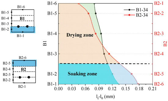
Figure 10.
The expansion distributions of B1 and B2.
The variation in swelling along the height of sections B1 and B2 at 34 months is illustrated in Figure 10. Significantly different distributions of swelling were observed between B1 and B2. In the soaking zone, where concrete comes into direct contact with the solution and contains abundant water and ions, a higher degree of expansion occurs. However, due to steel restraint, as depicted in Figure 11, the regional expansion index of B1 was comparatively smaller than that of B2. This can be attributed to the direct constraint imposed by steel reinforcement. ASR-induced expansion generates tensile stresses within reactive aggregate particles, while compressive stresses occur at their edges [5,21,46]. In reinforced beams, these expansion stresses result in tensile stresses. However, as shown in Figure 12, pre-tensioned stresses restrict concrete movement, thereby reducing ASR-induced expansion.
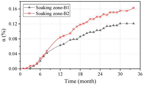
Figure 11.
Expansion indices of B1 and B2 soaking zones.
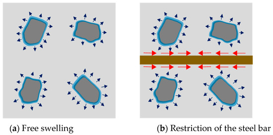
Figure 12.
The direct restraint effect of the steel bar. (Note: Blue arrows indicate aggregate alkali aggregate reaction, while red arrows indicate the direct restraining effect of the reinforcement.)
The expansion indices for the B1 and B2 dry zones are shown in Figure 13. In the drying zone, water and alkali ions permeate through the pores and cracks of concrete. Gels are initially formed near the cement paste and can partially migrate into the surrounding porosity [47]. Thus, the porosity of concrete plays a crucial role in facilitating ASR expansion. Generally, porous concrete enhances the aggregation of water and alkali ions from the environment, leading to aggregate dissolution and activation of ASR [44]. Moreover, cracks serve as pathways for gels, accelerating ASR; when interconnected, these cracks further increase permeability [48]. Therefore, as depicted in Figure 14, reinforcement enhances the compactness of the structure and diminishes the width of expansion-induced cracks in RC beams. The presence of reinforcement results in a reduced number of cracks, thereby decreasing permeability [49]. In B1, steel bars effectively restrain crack formation, leading to a denser structure that impedes ion and gel migration while minimizing expansion within this region. In contrast, B2 experiences direct restraint from reinforcement on expansion within this area. As illustrated in Figure 13, the disparity in expansion between B1 and B2 is notable under both direct restraint effects and indirect influences exerted by the steel bars.
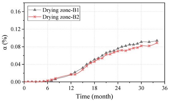
Figure 13.
Expansion indices of B1 and B2 drying zones.
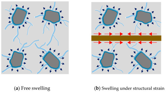
Figure 14.
The indirect restraint effect of the steel bar. (Note: Blue arrows indicate aggregate alkali aggregate reaction, while red arrows indicate the indirect restraining effect of the reinforcement.)
Figure 15 demonstrates that when the immersion depth of the NaOH solution is 100 mm, there is an accelerated development of swelling and a more severe deterioration. However, it also indicates that concrete expansion due to ASR is mitigated by restraint. Figure 16a illustrates that in the solution soaking zone, reinforcement directly restrains ASR-induced expansion, resulting in lower expansion for B3 compared to B4 without reinforcement. In the relative drying zone (Figure 16b), the presence of reinforcing steel bars leads to decreased permeability properties in concrete for B3 due to crack propagation inhibition, thereby influencing silica gel generation and migration [13]. For B4, direct restraint from steel bars restricts concrete expansion.
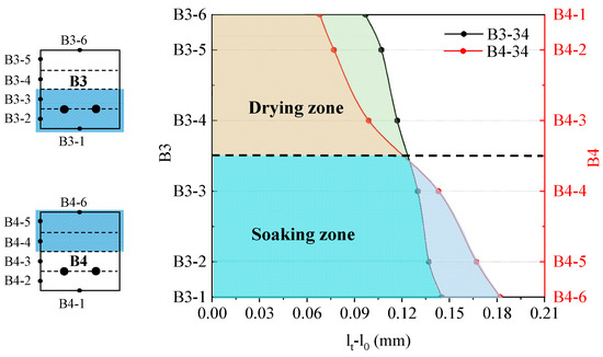
Figure 15.
The expansion distributions of B3 and B4.
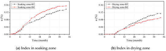
Figure 16.
Development of uneven deterioration index in different zones.
A model elucidating the effects of freeze–thaw cycles and alkali–silica reactions on the durability and fatigue life of a reinforced concrete bridge deck has been proposed [50]. However, it has been observed in actual engineering practice that ASR reactions may occur locally or partially in the girder or bridge deck, and using the existing model for analysis could lead to significant computational errors due to the characteristics of such localized or partial reactions. Therefore, our study focuses on accurately assessing and predicting the ASR expansion rate in different regions to evaluate its impact on structural performance. By collecting ASR data under various environmental and restraint conditions, we can calibrate the existing model to make it more reflective of real situations. Furthermore, future research will also consider other factors that may influence the ASR process, such as aggregate type and quality, cement chemical composition, concrete mix ratio, and construction techniques. These factors have potential implications for both ASR development and concrete structure durability.
4. Conclusions
In this study, accelerated ASR experiments on RC beams were conducted with different immersion location and depth. Six points were arranged along the height of the beams, and the expansion was measured monthly for an experimental period of up to 34 months. Subsequently, the spatial and temporal distribution characteristics of the swelling rate of the beams were analyzed. A beam local damage index was also proposed to quantify the damage in various regions of the beam and to illustrate the restraint mechanism of the reinforcement under the influence of ASR. The main findings of this study are as follows:
(1) The time distribution law of the expansion rate confirms that the alkali–aggregate reaction (ASR) is a continuous and multistage detrimental process for all beams. In the middle stage, the expansion rate of concrete due to ASR increases gradually but significantly, followed by a slower increase in the later stage. However, variations in soaking depth and position result in different expansion times during the first and second stages for each beam. Consequently, there are also discrepancies in the absolute value of expansion rates among individual beams.
(2) The expansion rate exhibited distinct spatial distribution characteristics, with higher rates observed in the regions directly immersed in the solution, and decreased rates around the steel bars. Significant variations were observed in the spatial distribution of beam expansion rates for RC beams subjected to different soaking positions and depths. In the initial phase of ASR in concrete, the expansion rate is typically quite gradual, as the reaction has just begun, and there is minimal formation of ASR gel. As ASR progresses into the second stage, micro-cracks generated within the concrete matrix facilitate a higher penetration rate of NaOH solution. This increased penetration, in turn, accelerates the ASR process, leading to a significantly higher expansion rate. The presence of cracks allows for more ready interaction between reactive silica and alkali solution, causing more rapid gel formation and subsequent expansion. However, the strain distribution across the beam cross-section generally aligned with the assumption of planar sections.
(3) Owing to ASR, obvious cracks appeared on the beam surface. At the top and bottom of the beam, the cracks in the area where the steel bars existed were reduced. On the lateral side, cracks were predominantly concentrated below the liquid level.
(4) The reinforcement influences the expansion properties of activated beams. On one hand, it generates tensile stress in response to the expansion stress of concrete in the solution soaking zone, directly restraining such stress. However, in reinforced concrete (RC) structures, the presence of steel bars enhances structural compactness and impedes alkali hydroxide and water transmission, thereby affecting gel formation and migration indirectly, consequently influencing inflation development.
Author Contributions
Conceptualization, F.S.; methodology, X.A. and F.S.; software, F.S.; validation, Y.W. and F.S.; formal analysis, F.S.; investigation, Y.Z.; resources, X.A.; data curation, F.S.; writing—original draft preparation, F.S.; writing—review and editing, F.S. and X.A.; visualization, Y.W.; supervision, X.A.; project administration, X.A.; funding acquisition, X.A. All authors have read and agreed to the published version of the manuscript.
Funding
This work was supported by the Chongqing Natural Science Foundation of China (CSTB2022NSCQ-MSX0509).
Data Availability Statement
The original contributions presented in the study are included in the article, further inquiries can be directed to the corresponding author.
Conflicts of Interest
Authors Feng Sheng, Yuan Wang and Yuxiang Zhou were employed by the company PowerChina Roadbridge Group Co., Ltd. The remaining author declare that the research was conducted in the absence of any commercial or financial relationships that could be construed as a potential conflict of interest.
References
- Zahedi, A.; Trottier, C.; Sanchez, L.F.; Noël, M. Microscopic assessment of ASR-affected concrete under confinement conditions. Cem. Concr. Res. 2021, 145, 106456. [Google Scholar] [CrossRef]
- Ahmed, H.U.; Mohammed, A.S.; Faraj, R.H.; Abdalla, A.A.; Qaidi, S.M.A.; Sor, N.H.; Mo-hammed, A.A. Innovative modeling techniques including MEP, ANN and FQ to forecast the compressive strength of geopolymer concrete modified with nanoparticles. Neural Comput. Appl. 2023, 35, 12453–12479. [Google Scholar] [CrossRef]
- Kakasor Ismael Jaf, D.; Ismael Abdulrahman, P.; Salih Mohammed, A.; Kurda, R.; Qaidi, S.M.A.; Asteris, P.G. Machine learning techniques and multi-scale models to evaluate the impact of silicon dioxide (SiO2) and calcium oxide (CaO) in fly ash on the compressive strength of green concrete. Constr. Build. Mater. 2023, 400, 132604. [Google Scholar] [CrossRef]
- Lu, C.; Bu, S.; Zheng, Y.; Kosa, K. Deterioration of concrete mechanical properties and fracture of steel bars caused by alkali-silica reaction: A review. Structures 2022, 35, 893–902. [Google Scholar] [CrossRef]
- Barbosa, R.A.; Hansen, S.G.; Hansen, K.K.; Hoang, L.C.; Grelk, B. Influence of alkali-silica reaction and crack orientation on the uniaxial compressive strength of concrete cores from slab bridges. Constr. Build. Mater. 2018, 176, 440–451. [Google Scholar] [CrossRef]
- Plusquellec, G.; Geiker, M.R.; Lindgård, J.; De Weerdt, K. Determining the free alkali metal content in concrete–Case study of an ASR-affected dam. Cem. Concr. Res. 2018, 105, 111–125. [Google Scholar] [CrossRef]
- Schmidt, J.W.; Hansen, S.G.; Barbosa, R.A.; Henriksen, A. Novel shear capacity testing of ASR damaged full scale concrete bridge. Eng. Struct. 2014, 79, 365–374. [Google Scholar] [CrossRef]
- Mohammadi, A.; Ghiasvand, E.; Nili, M. Relation between mechanical properties of concrete and alkali-silica reaction (ASR): A review. Constr. Build. Mater. 2020, 258, 119567. [Google Scholar] [CrossRef]
- Marzouk, H.; Langdon, S. The effect of alkali-aggregate reactivity on the mechanical properties of high and normal strength concrete. Cem. Concr. Compos. 2003, 25, 549–556. [Google Scholar] [CrossRef]
- Li, Z.; Afshinnia, K.; Rangaraju, P.R. Effect of alkali content of cement on properties of high performance cementitious mortar. Constr. Build. Mater. 2016, 102, 631–639. [Google Scholar] [CrossRef]
- Na, O.; Xi, Y.; Ou, E.; Saouma, V.E. The effects of alkali-silica reaction on the mechanical properties of concretes with three different types of reactive aggregate. Struct. Concr. 2016, 17, 74–83. [Google Scholar] [CrossRef]
- Sanchez, L.F.M.; Fournier, B.; Jolin, M.; Duchesne, J. Reliable quantification of AAR damage through assessment of the Damage Rating Index (DRI). Cem. Concr. Res. 2015, 67, 74–92. [Google Scholar] [CrossRef]
- Takahashi, Y.; Ogawa, S.; Tanaka, Y.; Maekawa, K. Scale-dependent ASR expansion of concrete and its prediction coupled with silica gel generation and migration. J. Adv. Concr. Technol. 2016, 14, 444–463. [Google Scholar] [CrossRef]
- Pan, J.; Wang, W.; Wang, J.; Bai, Y.; Wang, J. Influence of coarse aggregate size on deterioration of concrete affected by alkali-aggregate reaction. Constr. Build. Mater. 2022, 329, 127228. [Google Scholar] [CrossRef]
- Morenon, P.; Multon, S.; Sellier, A. Modelling the mechanical behaviour of concrete subjected to Alkali-Silica Reaction (ASR) under multi-axial stress. Cem. Concr. Res. 2022, 158, 106823. [Google Scholar] [CrossRef]
- Multon, S.; Toutlemonde, F. Effect of applied stresses on alkali–silica reaction-induced expansions. Cem. Concr. Res. 2006, 36, 912–920. [Google Scholar] [CrossRef]
- Multon, S.; Toutlemonde, F. Effect of moisture conditions and transfers on alkali silica reaction damaged structures. Cem. Concr. Res. 2010, 40, 924–934. [Google Scholar] [CrossRef]
- Morenon, P.; Multon, S.; Sellier, A.; Grimal, E.; Hamon, F.; Bourdarot, E. Impact of stresses and restraints on ASR expansion. Constr. Build. Mater. 2017, 140, 58–74. [Google Scholar] [CrossRef]
- Wald, D.M.; Allford, M.T.; Bayrak, O.; Hrynyk, T.D. Development and multiaxial distribution of expansions in reinforced concrete elements affected by alkali–silica reaction. Struct. Concr. 2017, 18, 914–928. [Google Scholar] [CrossRef]
- Morenon, P.; Multon, S.; Sellier, A.; Grimal, E.; Hamon, F.; Kolmayer, P. Flexural performance of reinforced concrete beams damaged by Alkali-Silica Reaction. Cem. Concr. Compos. 2019, 104, 103412. [Google Scholar] [CrossRef]
- Sogbossi, H.; Verdier, J.; Multon, S. Impact of reinforcement-concrete interfaces and cracking on gas transfer in concrete. Constr. Build. Mater. 2017, 157, 521–533. [Google Scholar] [CrossRef]
- Li, P.; Tan, N.; An, X.; Maekawa, K.; Ren, M. Effect of multi-directional restraint induced by reinforced steel bars on ASR expansion and bond performance. J. Adv. Concr. Technol. 2022, 20, 342–358. [Google Scholar] [CrossRef]
- Olajide, O.D.; Nokken, M.R.; Sanchez, L.F. Alkali–Silica Reactions: Literature Review on the Influence of Moisture and Temperature and the Knowledge Gap. Materials 2024, 17, 10. [Google Scholar] [CrossRef] [PubMed]
- Rivard, P.; Bérubé, M.A.; Ollivier, J.P.; Ballivy, G. Decrease of pore solution alkalinity in concrete tested for alkali-silica reaction. Mater. Struct. 2007, 40, 909–921. [Google Scholar] [CrossRef]
- Attar, A.; Gencturk, B.; Aryan, H.; Wei, J. Impact of Laboratory-Accelerated Aging Methods to Study Alkali–Silica Reaction and Reinforcement Corrosion on the Properties of Concrete. Materials 2020, 13, 3273. [Google Scholar] [CrossRef] [PubMed]
- JGJ 52-2006; Standard for Technical Requirements and Test Methodof Sand and Crushed Stone (or Gravel for Ordinary Concrete). China Architecture & Building Press: Beijing, China, 2006. (In Chinese)
- Souza LM, S.; Polder, R.B.; Çopuroğlu, O. Lithium migration in a two-chamber set-up as treatment against expansion due to alkali-silica reaction. Constr. Build. Mater. 2017, 134, 324–335. [Google Scholar] [CrossRef]
- Harbec, D.; Zidol, A.; Tagnit-Hamou, A.; Gitzhofer, F. Mechanical and durability properties of high performance glass fume concrete and mortars. Constr. Build. Mater. 2017, 134, 142–156. [Google Scholar] [CrossRef]
- Shao, G.; Li, S.; Liu, C.; Chen, G.; Qing, L. Study on the evolution of microcrack structure of concrete during alkali aggregate reaction. Water Resour. Hydropower Eng. 2019, 50 (Suppl. S1), 157–162. (In Chinese) [Google Scholar]
- Wang, Z.; Gong, F.; Maekawa, K. Multi-scale and multi-chemo–physics lifecycle evaluation of structural concrete under environmental and mechanical impacts. J. Intell. Constr. 2023, 1, 9180003. [Google Scholar] [CrossRef]
- Li, P.; Wang, H.; Nie, D.; Wang, D.; Wang, C. A method to analyze the long-term durability performance of underground reinforced concrete culvert structures under coupled mechanical and environmental loads. J. Intell. Constr. 2023, 1, 9180011. [Google Scholar] [CrossRef]
- Gong, F.; Maekawa, K. Multi-scale simulation of freeze-thaw damage to RC column and its restoring force characteristics. Eng. Struct. 2018, 156, 522–536. [Google Scholar] [CrossRef]
- Zhu, X.; Abe, H.; Hayashi, D.; Tanaka, H. Behavioral characteristics of RC beams with non-uniform corrosion along the reinforcement. J. Intell. Constr. 2023, 1, 9180019. [Google Scholar] [CrossRef]
- Sun, X.; Wang, S.; Jin, J.; Wang, Z.; Gong, F. Computational methods of mass transport in concrete under stress and crack conditions: A review. J. Intell. Constr. 2023, 1, 9180015. [Google Scholar] [CrossRef]
- ASTM C33/C33M-08; Standard Specification for Concrete Aggregates. ASTM International: West Conshohocken, PA, USA. (In Chinese)
- Hayashida, H.; Sato, Y.; Ueda, T. Failure behavior of RC beams in relation to the extent and location of frost damage. In Proceedings of the 3rd International Conference on the Durability of Concrete Structures, ICDCS 2012, Belfast, UK, 17–19 September 2012; Hokkaido University Press: Sapporo, Japan, 2012. [Google Scholar]
- Dron, R.; Brivot, F. Thermodynamic and kinetic approach to the alkali-silica reaction. Part 1: Concepts. Cem. Concr. Res. 1992, 22, 941–948. [Google Scholar] [CrossRef]
- Fan, S.; Hanson, J.M. Effect of alkali silica reaction expansion and cracking on structural behavior of reinforced concrete beams. ACI Struct. J. 1998, 95, 498–505. [Google Scholar]
- Martin, R.P.; Renaud, J.C.; Multon, S.; Toutlemonde, F. Structural behavior of plain and reinforced concrete beams affected by combined AAR and DEF. In Proceedings of the 14th International Conference on Alkali Aggregate Reaction ICAAR14, Austin, TX, USA, 20–25 May 2012; 10p. [Google Scholar]
- Figueira, R.B.; Sousa, R.; Coelho, L.; Azenha, M.; de Almeida, J.; Jorge, P.; da Silva, C.J.R. Alkali-silica reaction in concrete: Mechanisms, mitigation and test methods. Constr. Build. Mater. 2019, 222, 903–931. [Google Scholar] [CrossRef]
- Fournier, B.; Bérubé, M.A. Alkali-aggregate reaction in concrete: A review of basic concepts and engineering implications. Can. J. Civ. Eng. 2000, 27, 167–191. [Google Scholar] [CrossRef]
- Liaudat, J.; López Garello, C.M.; Carol, I. Diffusion-reaction model for alkali-silica reaction in concrete. In Proceedings of the COMPLAS XII: XII International Conference on Computational Plasticity: Fundamentals and Applications, Spain, Barcelona, 3–5 September 2013; CIMNE: Barcelona, Spain, 2013; pp. 479–489. [Google Scholar]
- Fanijo, E.O.; Kolawole, J.T.; Almakrab, A. Alkali-silica reaction (ASR) in concrete structures: Mechanisms, effects and evaluation test methods adopted in the United States. Case Stud. Constr. Mater. 2021, 15, e00563. [Google Scholar] [CrossRef]
- Islam, M.S.; Akhtar, S. A critical assessment to the performance of alkali–silica reaction (ASR) in concrete. Can. Chem. Trans. 2013, 1, 253–266. [Google Scholar]
- Ponce, J.M.; Batic, O.R. Different manifestations of the alkali-silica reaction in concrete according to the reaction kinetics of the reactive aggregate. Cem. Concr. Res. 2006, 36, 1148–1156. [Google Scholar] [CrossRef]
- Zahedi, A.; Trottier, C.; Sanchez LF, M.; Noël, M. Condition assessment of alkali-silica reaction affected concrete under various confinement conditions incorporating fine and coarse reactive aggregates. Cem. Concr. Res. 2022, 153, 106694. [Google Scholar] [CrossRef]
- Multon, S.; Sellier, A. Multi-scale analysis of alkali–silica reaction (ASR): Impact of alkali leaching on scale effects affecting expansion tests. Cem. Concr. Res. 2016, 81, 122–133. [Google Scholar] [CrossRef]
- Choinska, M.; Khelidj, A.; Chatzigeorgiou, G.; Pijaudier-Cabot, G. Effects and interactions of temperature and stress-level related damage on permeability of concrete. Cem. Concr. Res. 2007, 37, 79–88. [Google Scholar] [CrossRef]
- Picandet, V.; Khelidj, A.; Bastian, G. Effect of axial compressive damage on gas permeability of ordinary and high-performance concrete. Cem. Concr. Res. 2001, 31, 1525–1532. [Google Scholar] [CrossRef]
- Gong, F.; Sun, X.; Takahashi, Y.; Maekawa, K.; Jin, W. Computational modeling of combined frost damage and alkali–silica reaction on the durability and fatigue life of RC bridge decks. J. Intell. Constr. 2023, 1, 9180001. [Google Scholar] [CrossRef]


Disclaimer/Publisher’s Note: The statements, opinions and data contained in all publications are solely those of the individual author(s) and contributor(s) and not of MDPI and/or the editor(s). MDPI and/or the editor(s) disclaim responsibility for any injury to people or property resulting from any ideas, methods, instructions or products referred to in the content. |
© 2024 by the authors. Licensee MDPI, Basel, Switzerland. This article is an open access article distributed under the terms and conditions of the Creative Commons Attribution (CC BY) license (https://creativecommons.org/licenses/by/4.0/).