Abstract
Economic limitations often hinder the extensive use of fiber-reinforced concrete in full-scale structures. Addressing this, the present study explored localized reinforcement at critical interfaces, deploying a novel synchronized casting mold that deviates from segmented casting interface studies. The research prioritized the flexural, compressive, and shear characteristics at the interface between fiber-reinforced concrete and ordinary concrete with continuous casting. The results demonstrated that polyethylene (PE) fibers significantly enhance anti-cracking capabilities, surpassing steel fibers in all mechanical tests. PE fibers’ high modulus of elasticity and tensile strength considerably augmented the interface’s bending resistance, facilitating better load transfer and capitalizing on the fibers’ tensile properties. Additionally, their low density and greater dispersion negated the sinking behavior typical of steel fibers, thereby strengthening the compressive capacity of the interface. Although a 0.75% PE fiber volume is ideal for ductility, volumes as low as 0.25% or 0.5% are economically viable if dispersion is optimal. Conversely, steel fibers, prone to sinking and clustering, offer inferior shear resistance at the interface than PE fibers, marking a significant finding for structural applications.
1. Introduction
In recent years, the construction industry has seen a notable shift toward enhancing the toughness and cost-effectiveness of concrete structures through the local integration of steel and polymer fibers [1,2,3,4,5,6,7,8]. This strategic reinforcement, often deployed in specific areas within traditional concrete structures, aims to strengthen those locales where robustness is crucial. However, this practice has revealed that the interfaces between fiber-reinforced and conventional concrete tend to be the most vulnerable points within the structure [9,10,11,12,13,14].
Extensive research has been dedicated to understanding the bond and shear properties at these interfaces [15,16]. Historically, such studies involved cutting through existing concrete, roughening the interfaces [15,17,18,19,20], and casting the fiber-reinforced concrete to assess the interfacial shear and bond strengths. While these methods have provided valuable insights into the behavior of composite materials under stress, they have often overlooked the full potential of continuous casting practices and there is currently no established theoretical framework for continuous casting interfaces [21,22,23,24].
Continuous casting, particularly in the creation of monolithic structures, has emerged as a transformative advancement, blending structural robustness with economic and operational efficiencies. This technique allows for the seamless integration of different types of concrete in a single pour, enhancing localized strengthening at crucial points within the structure where enhanced toughness and crack resistance are most needed. Additionally, the inclusion of steel and polymer fibers at these interfaces not only promotes durability but also drives economic benefits by minimizing maintenance demands and construction times.
Despite the advantages, significant gaps remain in our understanding of how these continuous construction practices affect the interfacial integrity and performance of composite concrete structures. Traditional studies have fallen short in capturing the complexities of monolithic casting, where different structure segments are poured in an uninterrupted process [16,19,25,26,27]. Moreover, the dynamics of crack formation and propagation at these interfaces are not fully understood, which are often the initial points of failure that can substantially reduce the lifespan and safety of the structures [28,29].
To bridge these knowledge gaps, this study introduces an innovative one-step casting process that explores the simultaneous pouring of dual-concrete systems, designed to more closely replicate real-world continuous construction conditions. This approach aims to provide a more accurate depiction of material behavior in situ, focusing on the dynamics of interface behavior, stress management, and crack propagation. A pivotal element of this research is the utilization of Digital Image Correlation (DIC) technology. This non-intrusive technique measures displacements and monitors crack behavior throughout the structure’s lifecycle, offering detailed insights into how these interfaces handle stresses and accommodate crack propagation. Given that there are currently no comparable methods to DIC for non-contact, full-field strain analysis in concrete, the study did not include a comparative analysis with other techniques. By leveraging DIC, this study not only deepens our understanding of the interfacial characteristics between continuously cast fiber-reinforced and conventional concrete, but also contributes to developing more efficient construction methodologies.
2. Experimental Program
2.1. Material Preparation
In the research focused on understanding the interface characteristics between different types of fiber-reinforced concrete and conventional concrete in continuous casting settings, a baseline ordinary concrete mix served as the foundation for all the experimental configurations. This standard mix comprised 357 kg of cement, 45 kg of slag, 45 kg of fly ash, 731 kg of fine aggregate, 1097 kg of coarse aggregate, 138 L of water, and 3.3525 kg of a water-reducing agent.
To explore the impact of fiber reinforcement on concrete interfaces, steel and polyethylene (PE) fibers were incorporated directly into this baseline mix at specified volumetric ratios. Since the study primarily investigated the interfacial mechanical properties of fiber-reinforced and conventional concrete in continuous casting, it utilized two common fiber materials.
For the steel fiber-reinforced concrete mixes, steel fibers were added to the baseline mix in varying volumetric ratios of 0.25%, 0.50%, and 0.75%. These ratios were designed to test the effects of mild, moderate, and extensive reinforcement, respectively. Steel fibers, known for their high tensile strength and stiffness, are typically used to enhance the load-bearing capacity and crack resistance of concrete. However, they also present challenges such as a higher density, which could lead to sinking and clumping within the mix, and potential corrosion issues when exposed to chloride ions, potentially compromising the durability of the concrete structure.
Conversely, the PE fiber-reinforced concrete mixes incorporated high-strength, high-modulus PE fibers at the same volumetric ratios as the steel fibers. PE fibers, chosen for their durability and chemical resistance, offer advantages over steel fibers. Their lighter weight reduces the likelihood of sinking and clumping, making them ideal for improving the uniformity of the concrete mix and enhancing its overall toughness and impact resistance. By integrating PE fibers into the concrete, this study aimed to assess their contribution to improving the bonding and shear properties at the interface with conventional concrete, thus addressing issues related to interface integrity and performance.
This study focused on two types of fibers for initial investigation. However, to address the question of wider variation in the parameters, it is acknowledged that other fiber types, such as other metals, polypropylene, and polyamide fibers, could have been but were not included in this study and warrant further research. The mix proportions presented in Table 1 show the specified fibers and volumetric ratios used in this research. Table 2 shows the parameters of fibers. Figure 1 shows the fiber type.

Table 1.
Mixture proportions.
Table 2.
Parameters of fibers.
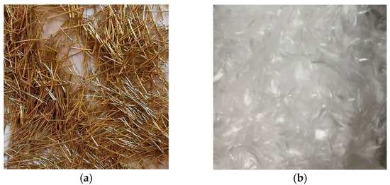
Figure 1.
Fiber types: (a) steel fibers and (b) PE fibers.
Each type of fiber was thoroughly mixed with the baseline concrete to ensure an even distribution and optimal integration of the fibers within the mix. This method maintained the integrity of the baseline formula while allowing for a precise evaluation of the fibers’ contributions to the interface characteristics. The objective was to determine how different materials cooperated under a load and how they influenced the interfacial bond strength, which is critical for the overall performance of composite structures in continuous casting scenarios.
2.2. Mold and Sample for Continuous Casting
In the study of continuous casting for concrete structures, the mixing process is a critical step to ensure uniformity and optimal properties of the concrete. To achieve this, two drum mixers were utilized, operating synchronously at a rate of 40 revolutions per minute. The mixing sequence was meticulously planned to enhance the material properties and facilitate the integration of fibers and aggregates. Initially, cementitious materials and sand were thoroughly mixed for two minutes to ensure a homogeneous mixture. This was followed by the addition of water and a water-reducing agent, which were blended for five minutes to achieve a consistent and workable slurry.
Subsequently, fibers and coarse aggregates were added and mixed for an additional three minutes. This step was crucial as it ensured that the fibers were evenly dispersed throughout the mix without significant clumping, which is vital for maintaining the structural integrity and uniformity of the concrete. Once the mixing process was complete, the concrete was poured into molds. The mix was then vibrated to ensure proper compaction and molding of the structure, followed by covering with a thin film to facilitate curing.
After 24 h, the concrete was demolded and subjected to a standard curing process in a controlled environment for 28 days. Following this period, mechanical testing was conducted to assess the properties of the concrete. According to the China Standard [30], various tests were employed to evaluate the concrete’s performance. These included a four-point bending test using samples measuring 100 mm × 100 mm × 400 mm, compressive strength tests with 100 mm × 100 mm × 100 mm samples, and shear tests using 100 mm × 100 mm × 300 mm samples.
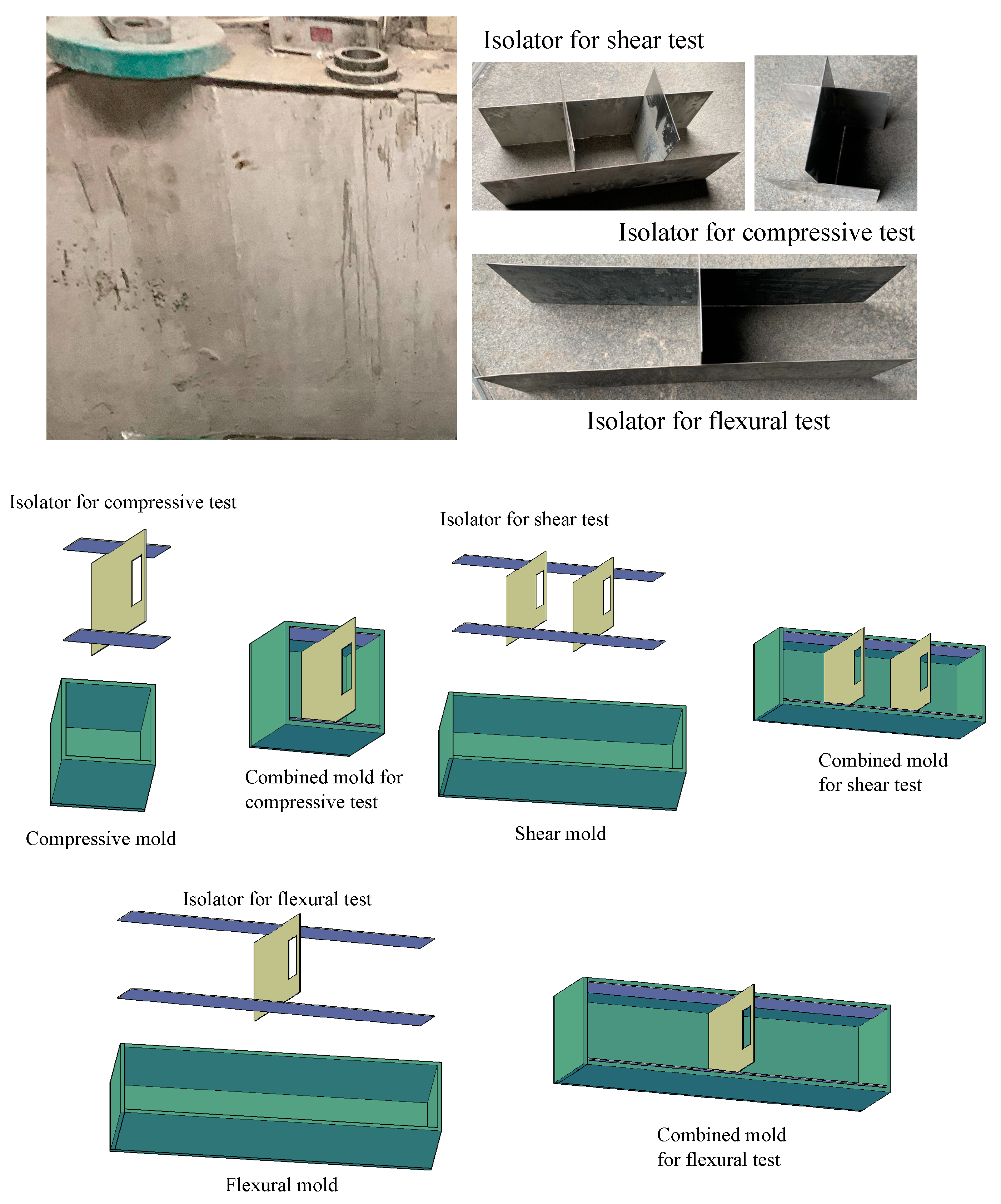
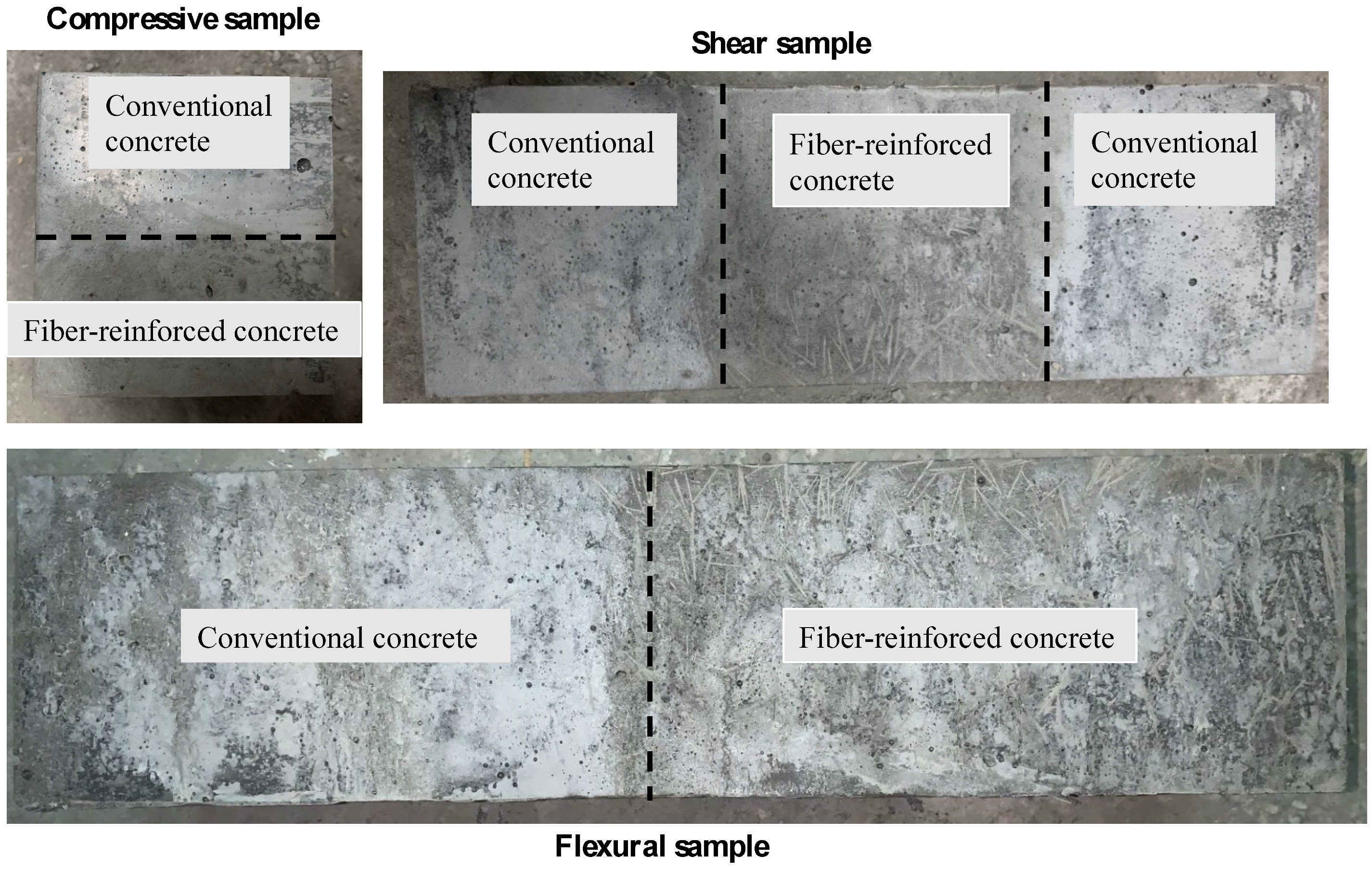
An innovative aspect of this study involved the use of stainless-steel isolators within the molds, which could be tightly embedded and divide the mold in half, as shown in Figure 2. This setup allowed for the simultaneous mixing and pouring of two different types of concrete. The concrete was filled slightly above the height of the mold to ensure that when the isolator was removed, the space it occupied was adequately filled, allowing for complete and seamless contact between the two types of concrete. The extraction of the isolator and the vibration process were synchronized to maximize the contact area between the different concrete types, which is critical for the integrity of the interface. The final molded specimens are depicted in Figure 3. The synchronized casting mold allows for the simultaneous pouring of fiber-reinforced and conventional concrete. This technique enables the testing of the flexural, compressive, and shear performance at the interfaces of different samples, providing highly relevant results for real-world high-performance localized reinforcement.

Figure 2.
Mold design.
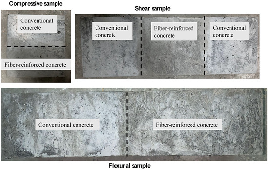
Figure 3.
Molded specimens.
2.3. Testing Equipment and Set Up
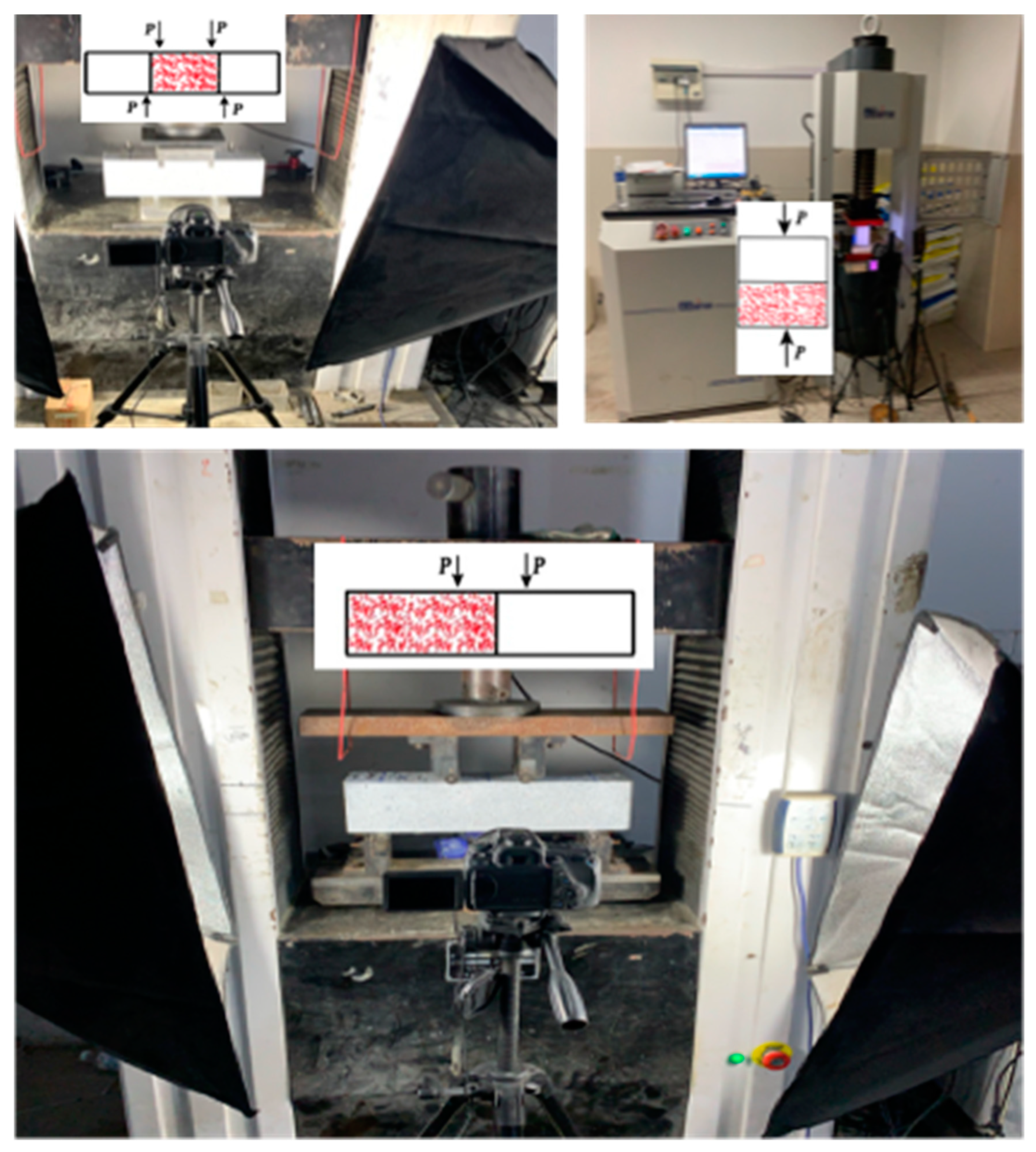
The experimental setup for testing the interface performance between fiber-reinforced concrete and conventional concrete in continuous casting was intricately designed to deliver precise and insightful data, as shown in Figure 4. The setup was centered around a universal testing machine that was carefully calibrated to apply stress to the concrete specimens through displacement control at a steady rate of 0.5 mm/min. The controlled application of load was essential to replicate the realistic stresses that materials would face in actual structural applications.

Figure 4.
Testing equipment.
The preparation of the concrete specimens for testing involved a unique process where their surfaces were sprayed with a non-uniform black and white speckle pattern. This speckle pattern was critical for the Digital Image Correlation (DIC) technique, as it provided a detailed map of speckles that served as reference points throughout the loading process. A high-resolution digital camera was strategically positioned to capture the speckles’ displacement as the load was applied. The DIC system analyzed these images to calculate the full-field displacements across the specimen’s surface, offering a detailed visualization of the strain distribution and potential failure points.
The DIC technique, with its non-contact measurement approach, allowed for the observation of the minute changes on the surface of the concrete without interfering with the specimen’s behavior under stress. This advanced method of analysis not only yielded the mechanical properties of the materials but also unveiled the complex interaction at the interface of the fiber-reinforced and conventional concrete segments, capturing the evolution of strain and the initiation and propagation of cracks.
2.4. Methodology
The research methodology involved preparing specimens of ordinary concrete and fiber-reinforced concrete, followed by conducting interface tests to evaluate their mechanical properties. The tests included bending, shear, and compression to measure flexural strength, shear strength, and compressive strength, respectively. The analysis focused on the load-bearing capacity and failure modes at the interfaces, providing insights into the performance and behavior of fiber-reinforced concrete in continuous casting settings. This approach facilitated a comprehensive understanding of how fiber reinforcement affects the interfacial characteristics and overall structural integrity.
3. Experimental Results
3.1. Flexural Properties for Interface
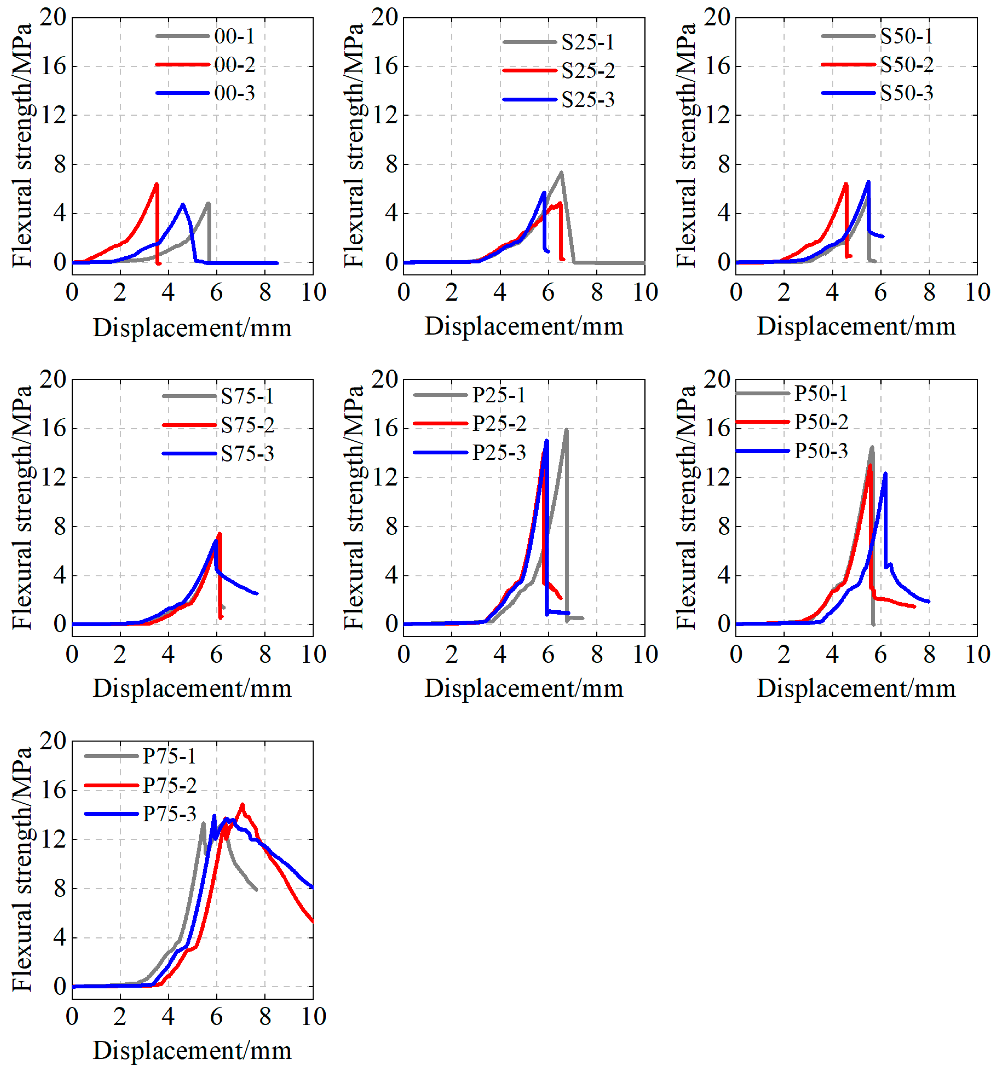
The analysis of the flexural strength data from Figure 5 and Figure 6 revealed a significant impact of fiber integration on the performance of the concrete. The control samples without fibers presented an average flexural strength of 5.4 MPa, whereas the inclusion of fibers led to varying degrees of strength enhancement, depending on the type and volume of fibers used.
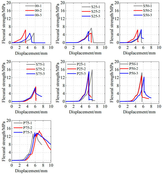
Figure 5.
Displacement–flexural strength relationships.

Figure 6.
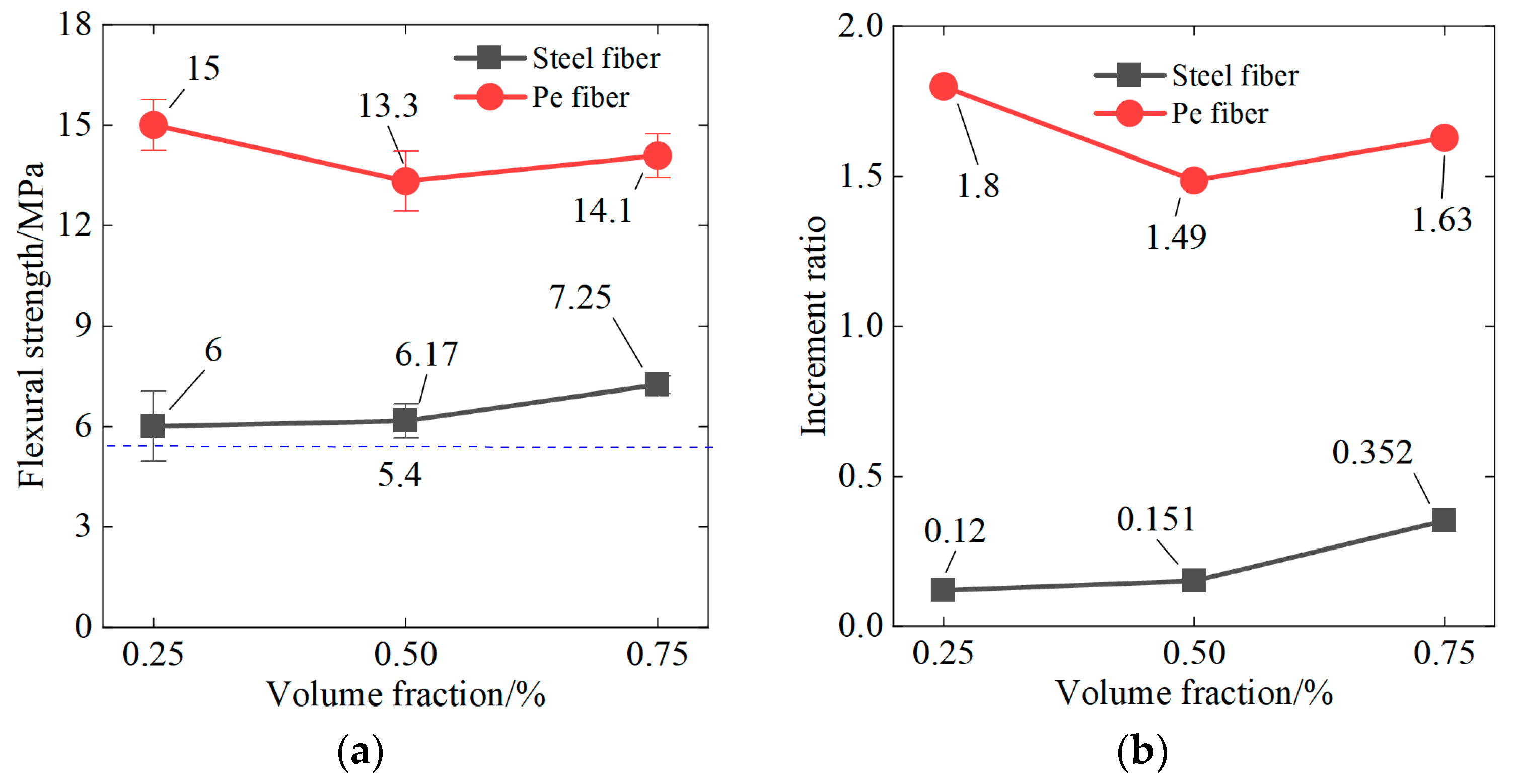
Flexural properties: (a) flexural strength and (b) increment ratio relative to the control group.
Starting with the steel fibers, the S25 group experienced an average strength increase of approximately 11% compared to the control group, but with the highest variability (C.o.V of 17.41%). This suggested a non-linear relationship between the fiber content and the material performance, potentially due to the non-uniform distribution of fibers. The S50 group, with a mean flexural strength of 6.2 MPa, represented an approximate 15% increase over the control, combining improved strength with reduced variability (C.o.V of 8.30%). The S75 group’s mean strength of 7.2 MPa marked a substantial increase of about 33% over the control, with the lowest variability among the steel-fiber-reinforced samples (C.o.V of 3.59%). The data suggested a positive correlation between the volume of steel fibers and flexural strength, up to a certain point. Beyond this point, the benefits may level off or even decline due to factors such as fiber clumping and workability issues. It was essential to balance the amount of steel fibers to avoid compromising the mix’s homogeneity, which is critical for consistent flexural performance.
The polyethylene fibers displayed a more pronounced effect on flexural strength. The P25 group achieved an average strength of 15.0 MPa, an impressive rise of approximately 178% compared to the non-fiber-reinforced samples, while maintaining a low C.o.V of 5.08%. The P50 group’s mean strength of 13.3 MPa still marked an increase of roughly 146%, and the P75 group’s 14.1 MPa represented a 161% increase, with C.o.Vs of 6.75% and 4.56%, respectively. The reduced variability, as well as the significant increase in strength, underlined the efficiency of PE fibers in enhancing concrete’s flexural capacity. Interestingly, while PE fibers consistently outperformed steel fibers in terms of strength enhancement, and the increase did not scale linearly with fiber content. For instance, the P50 and P75 groups did not exhibit proportional increases in strength with the increased fiber content; instead, there was a slight decline in performance compared to the P25 group. This could be attributed to the physical properties of PE fibers, which differ from steel fibers in terms of density, bonding, and interaction with the concrete matrix. It indicated that there is an optimal fiber volume where the performance peaks, and any further addition might not contribute to strength increases.
The juxtaposition of the performance between steel and PE fibers in concrete suggested that while both materials improve flexural strength, the mechanism of enhancement, the extent of improvement, and the impact on variability differed. PE fibers led to a more significant increase in strength and less variability, likely due to their high tensile strength, better bonding with the matrix, and improved distribution throughout the concrete. These characteristics of PE fibers contribute to their ability to control crack propagation effectively, a critical factor in flexural strength performance. In conclusion, fiber reinforcement markedly improved the flexural strength of concrete, with PE fibers demonstrating superior performance over steel fibers in this regard. The optimal volume fraction of fibers is crucial to maximize strength gains while minimizing variability, ensuring reliable and predictable behavior in concrete structures. These insights underscore the importance of selecting the appropriate type and amount of fibers to leverage the full potential of fiber-reinforced concrete for structural applications.
3.2. Compressive Properties for Interface
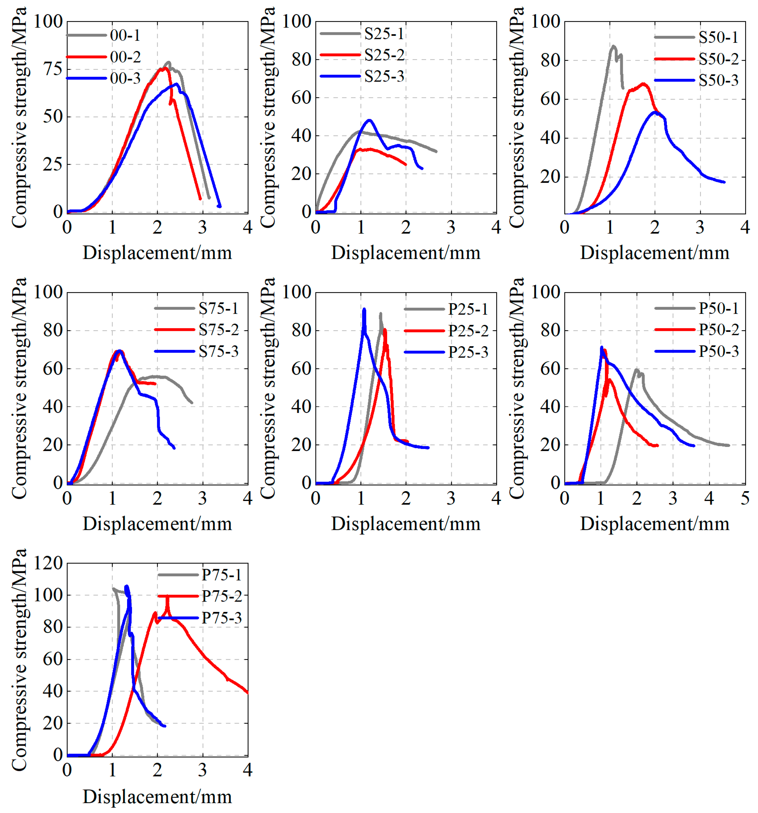
The compressive strength data from Figure 7 and Figure 8 show the influence of fiber reinforcement on the behavior of concrete under compression. The samples without fibers, representing the baseline, exhibited an average compressive strength of 74.0 MPa with a standard deviation of 4.9 MPa, translating into a coefficient of variation (C.o.V) of 6.61%. This set established a standard against which the performance enhancements or detractions provided by fiber incorporation were measured.

Figure 7.
Displacement–compressive strength relationships.

Figure 8.
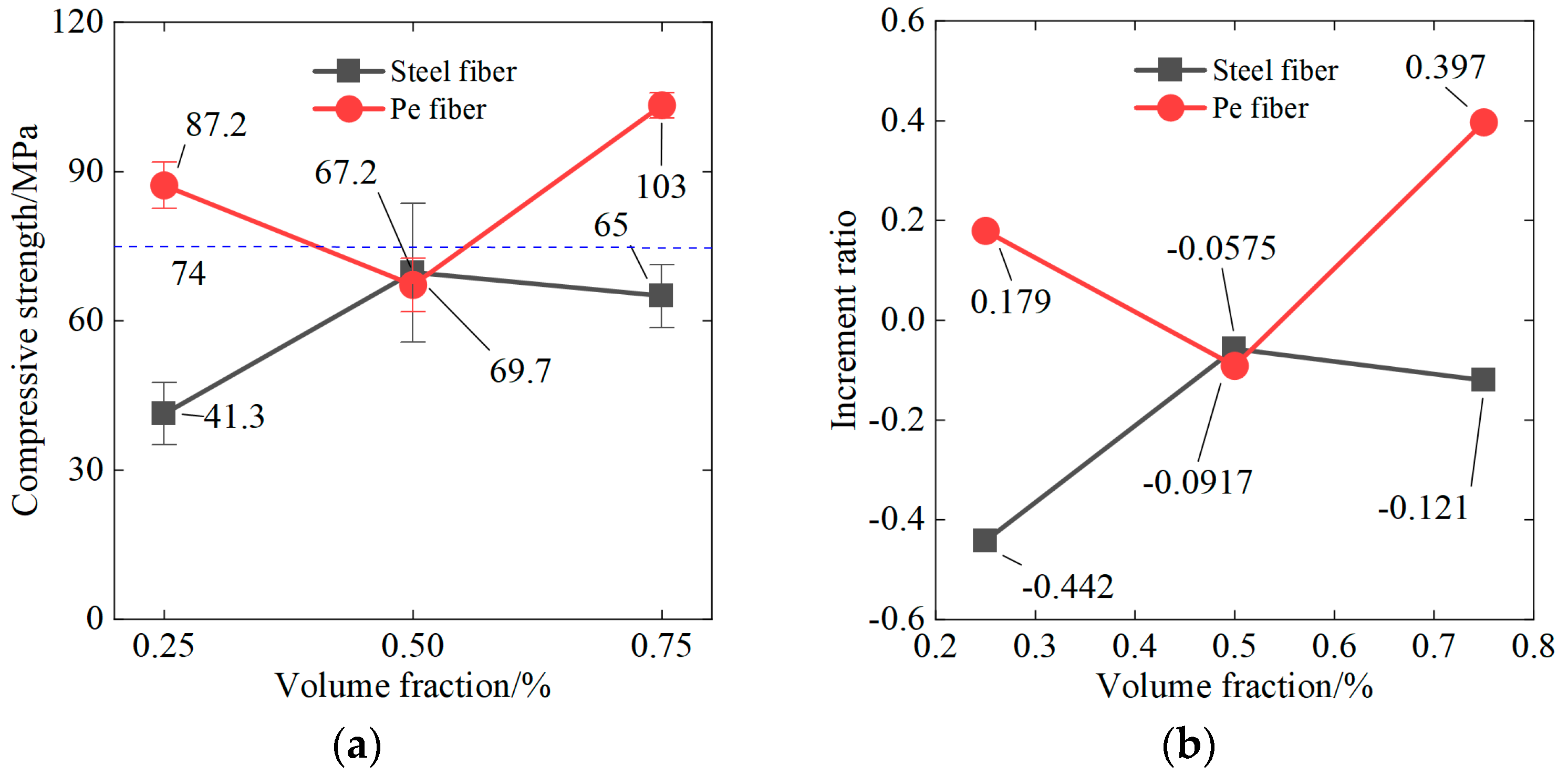
Compressive properties: (a) compressive strength and (b) increment ratio relative to the control group.
When steel fibers were introduced (S25, S50, S75), a diverse set of outcomes emerged. The S25 sample group showed a decreased average compressive strength of 41.3 MPa, which was approximately 44% lower than that of the control group. Moreover, it exhibited a higher C.o.V of 15.01%, indicating significant variability in strength, possibly due to the fibers’ orientation or distribution within the concrete. The S50 group’s average strength further declined to 69.7 MPa, representing a 6% decrease compared to the control, coupled with a C.o.V of 20.01%, the highest among all groups, suggesting an even greater inconsistency in the distribution or alignment of fibers. Conversely, the S75 group demonstrated an improvement in average compressive strength to 65.0 MPa, although this was still about 12% lower than that of the control. The reduction in C.o.V to 9.72% indicated a more consistent performance across this sample group, possibly reflecting a threshold in fiber content where the benefits began to manifest more uniformly.
The integration of polyethylene fibers (P25, P50, and P75) presented a contrasting trend. The P25 group achieved an average compressive strength of 87.2 MPa, which was an increase of about 18% over the non-fiber-reinforced concrete, and it maintained a lower C.o.V of 5.30%. This improvement underscored the PE fibers’ ability to distribute stress more evenly and prevent crack propagation, enhancing the material’s overall compressive strength. For the P50 group, there was a slight decrease in mean strength to 67.2 MPa, roughly 9% lower than that of the control group, and a C.o.V of 7.96%, indicating good consistency but less enhancement than the P25 group. Most notably, the P75 group exhibited a substantial increase in average compressive strength, reaching 103.3 MPa, which was nearly 40% higher than that of the baseline group. The low C.o.V of 2.49% in the P75 group signified the most consistent strength performance among all sample groups, suggesting that a higher volume of PE fibers results in a denser and more homogenous concrete matrix, significantly enhancing the material’s ability to withstand compressive forces.
The data suggested that while steel fibers could decrease the compressive strength and increase variability, an optimal content or distribution could yield improvements. On the other hand, PE fibers consistently enhanced the compressive strength of concrete, particularly at higher volume fractions, and reduced variability, indicating a more uniform distribution of fibers and a better interaction with the concrete matrix. This emphasized the importance of fiber type selection and proper mixing techniques to achieve enhanced concrete properties.
3.3. Shear Properties for Interface
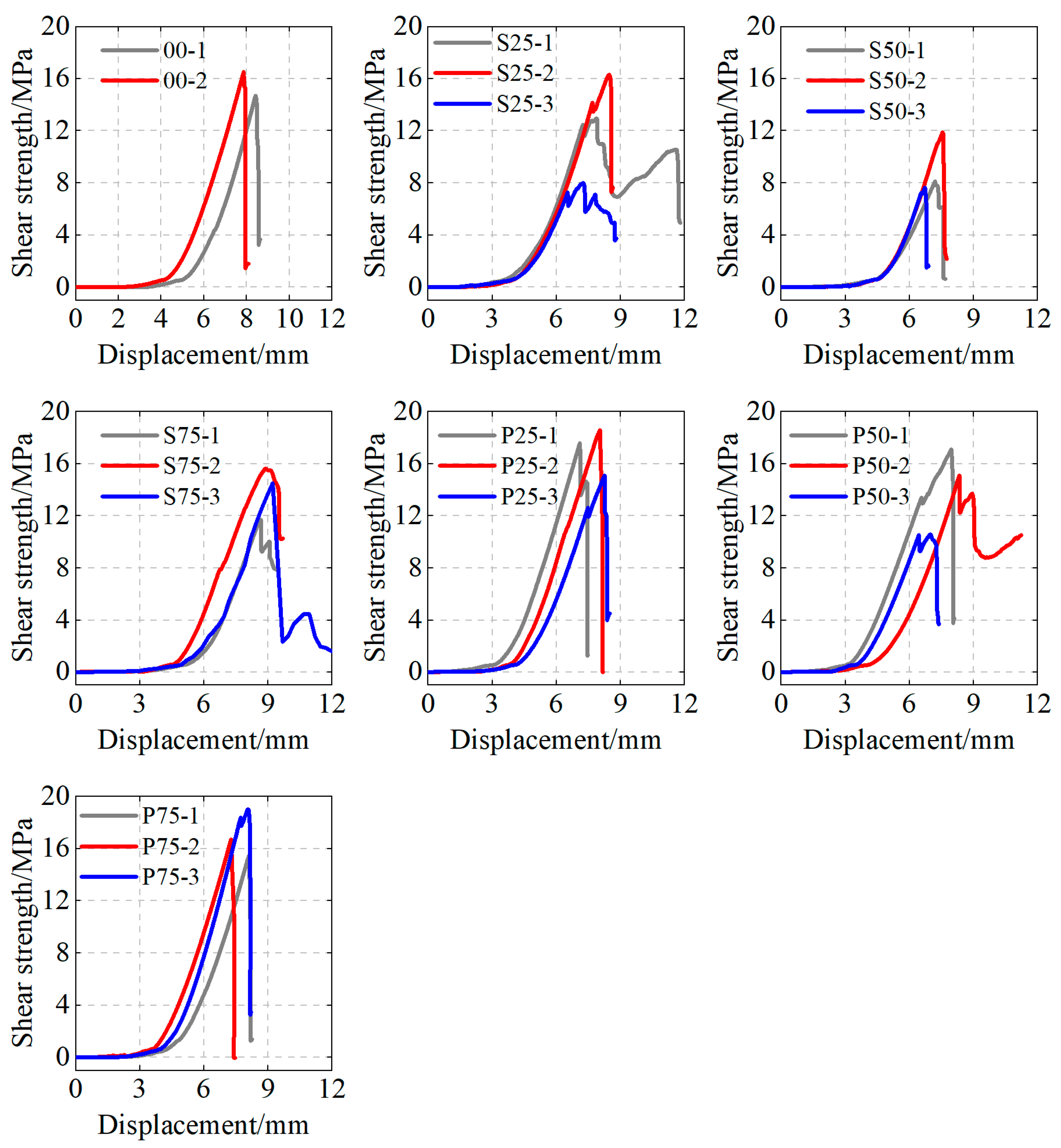
The shear strength data presented in Figure 9 and Figure 10 for fiber-reinforced and conventional concrete provided critical insights into how the addition of fibers influenced the shear resistance of the interface. The control samples, void of any fibers, exhibited a mean shear strength of 15.6 MPa, which was used as the baseline for comparison of the fiber-reinforced variants. The standard deviation for this group was relatively low at 0.9 MPa, resulting in a coefficient of variation (C.o.V) of 5.86%, indicating a consistent performance within the conventional concrete group.

Figure 9.
Displacement–shear strength relationships.

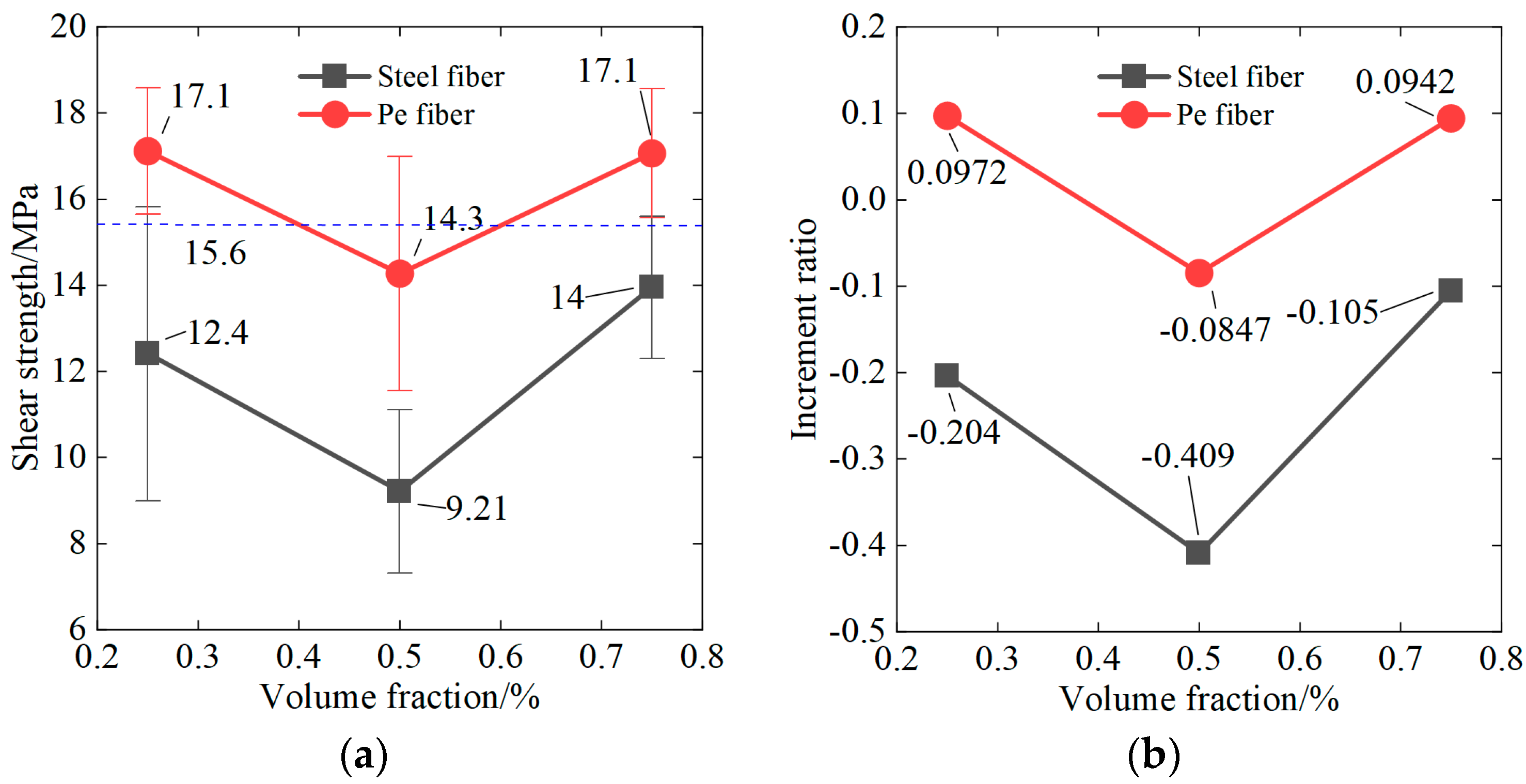
Figure 10.
Shear properties: (a) shear strength and (b) increment ratio relative to the control group.
Upon the integration of steel fibers (S25, S50, and S75), there was a notable trend in the impact on shear strength. The S25 group displayed an average shear strength of 12.4 MPa, representing a decrease of about 20% compare to the control. The variability within this group was significantly high, with a C.o.V of 27.51%, suggesting that the presence of steel fibers at this volume might introduce inconsistencies in the material’s shear performance. The S50 group exhibited a further reduction in mean shear strength to 9.2 MPa, which was approximately 41% lower than the control group’s average. The C.o.V for S50 stood at 20.61%, indicating substantial variability and potentially implying that the alignment and distribution of steel fibers critically affected the shear strength at this fiber content level. Conversely, the S75 group presented an average shear strength of 14.0 MPa, about a 10% decrease compared to the control. Despite the reduction, the C.o.V improved to 11.78%, which suggests that a higher volume fraction of steel fibers may contribute to a more homogenous dispersion within the concrete, albeit not sufficient to surpass the control’s performance.
In the polyethylene (PE) fiber groups, a different performance pattern emerged. The P25 group achieved an average shear strength of 17.1 MPa, marking an approximate 10% improvement over the control group. With a C.o.V of 8.55%, the PE fibers’ performance was more consistent than the S25 group, although it was not as consistent as that of the control. The P50 group’s mean shear strength decreased slightly to 14.3 MPa, about 8% lower than the control, with a C.o.V of 19.06%, which indicates considerable variability within this group. This suggests that there might be an optimal fiber content that maximizes shear strength, and the P50 volume might exceed it. Interestingly, the P75 group saw an increase back to an average shear strength of 17.1 MPa, aligning with the P25 group and outperforming the control by about 10%. The consistency of performance also improved, with a C.o.V comparable to the P25 group at 8.76%. This could indicate that the PE fibers at this volume fraction contributed to a more uniform distribution within the matrix, enhancing the shear strength of the concrete.
The data revealed a complex relationship between fiber type, volume, and concrete shear strength. While steel fibers at the volumes studied generally led to a decrease in shear strength and increased variability, PE fibers demonstrated the potential to enhance shear strength, particularly at higher volume fractions. The performance of PE fibers in shear strength improvements can be attributed to their tensile properties, bonding characteristics, and perhaps a more favorable interaction with the concrete matrix. In summary, the incorporation of fibers into concrete altered its shear strength in a non-linear manner. The findings suggest that PE fibers, especially at higher concentrations, have the potential to enhance shear strength with less variability, underscoring the importance of optimizing the fiber volume and distribution within the concrete to maximize the benefits. This analysis highlights the intricate balance required when designing fiber-reinforced concrete to improve shear resistance, crucial for the structural integrity of concrete applications.
4. Discussion
4.1. Flexural Cracking Evolution
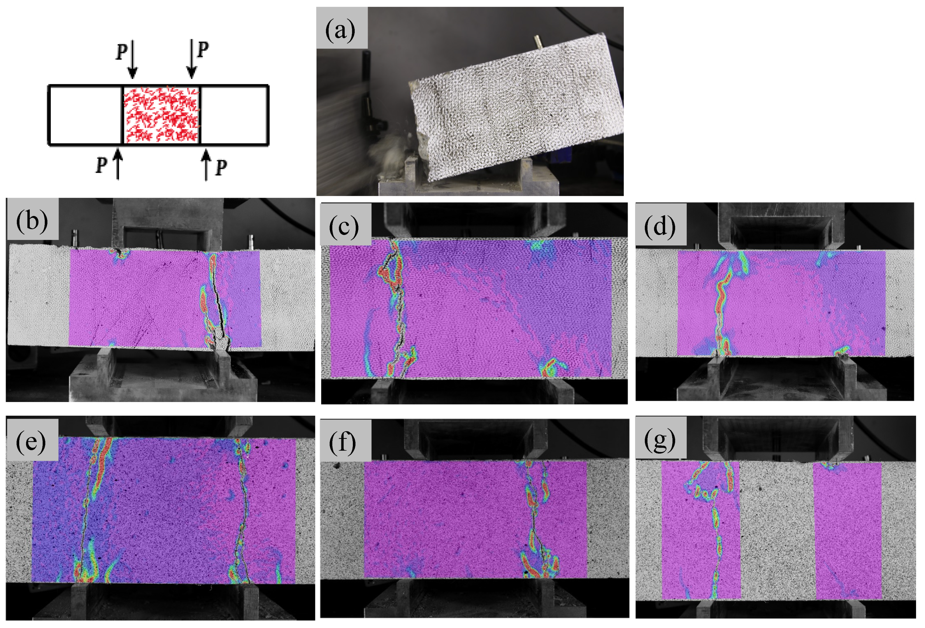
As shown in Figure 11, crack evolution during the four-point bending process, as captured by Digital Image Correlation (DIC), provided a nuanced understanding of the distinct behaviors of non-fiber-reinforced concrete, steel fiber-reinforced concrete, and polyethylene (PE) fiber-reinforced concrete at the interface.
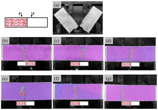
Figure 11.
Flexural cracking: (a) 00, (b) S25, (c) S50, (d) S75, (e) P25, (f) P50, and (g) P75.
In the non-fiber-reinforced concrete specimens, the observed failure was characteristically brittle. Upon reaching the peak load, the specimens exhibited a failure mode that resulted in a clean bifurcation across the middle section. This type of brittle fracture, common in conventional concrete, lacked post-peak load-carrying capacity, indicative of minimal energy absorption prior to failure. The steel fiber-reinforced concrete showed a departure from this brittle failure mode. The initiation of cracks at the specimen’s mid-lower region, and their subsequent upward progression, highlighted the role of steel fibers. These fibers, acting as bridges across emerging cracks, redirected crack paths towards the conventional concrete. The bridging effect of steel fibers prevented the sudden failure seen in non-fiber-reinforced specimens, introducing a degree of ductility and resistance against the propagation of cracks. In the PE fiber-reinforced concrete specimens, the crack initiation was observed to be biased towards the side with PE fibers. As the load increased, cracks continued to develop within the PE fiber side, up until the point of failure. Interestingly, the increase in PE fiber volume from 0.25% to 0.75% resulted in a notable increase in ductility. This was evidenced by the pronounced post-peak region in the load–displacement curve, indicating the material’s ability to undergo significant deformations before failure.
Table 3 illustrates the flexural performance of various fiber-reinforced concrete samples under continuous casting conditions by measuring the average crack width. The baseline sample (00) showed an average crack width of 0.50 mm. When steel fibers were introduced (S25, S50, and S75), a significant reduction in the crack width was observed, demonstrating the effectiveness of fiber reinforcement. Specifically, the S25 sample reduced the average crack width to 0.40 mm, which is a 20% reduction relative to the baseline. More pronounced improvements were seen with higher fiber contents: the S50 sample exhibited an average crack width of 0.30 mm, representing a 40% reduction, while the S75 sample achieved an impressive reduction to 0.20 mm, corresponding to a 60% decrease. In parallel, the inclusion of polyethylene fibers (P25, P50, and P75) also resulted in improved flexural performance. The P25 sample achieved an average crack width of 0.35 mm, marking a 30% reduction from the baseline. Further reductions were observed with higher fiber contents: the P50 sample had an average crack width of 0.25 mm, a 50% reduction, and the P75 sample exhibited the highest improvement with an average crack width of 0.15 mm, reflecting a substantial 70% reduction.
Table 3.
Average crack width in flexural test.
The analysis revealed that the position of failure in the PE fiber-reinforced concrete remained consistently on the PE fiber side, yet the load-bearing capacity significantly surpassed that of the steel fiber-reinforced interfaces. The angulation of forces on the PE fiber interface suggested that PE fibers facilitated a more effective stress distribution, allowing the fiber-reinforced concrete to bear more stress and thus alleviating the load on the conventional concrete side. This resulted in an elevated overall interface load-bearing capacity.
4.2. Compressive Cracking Evolution
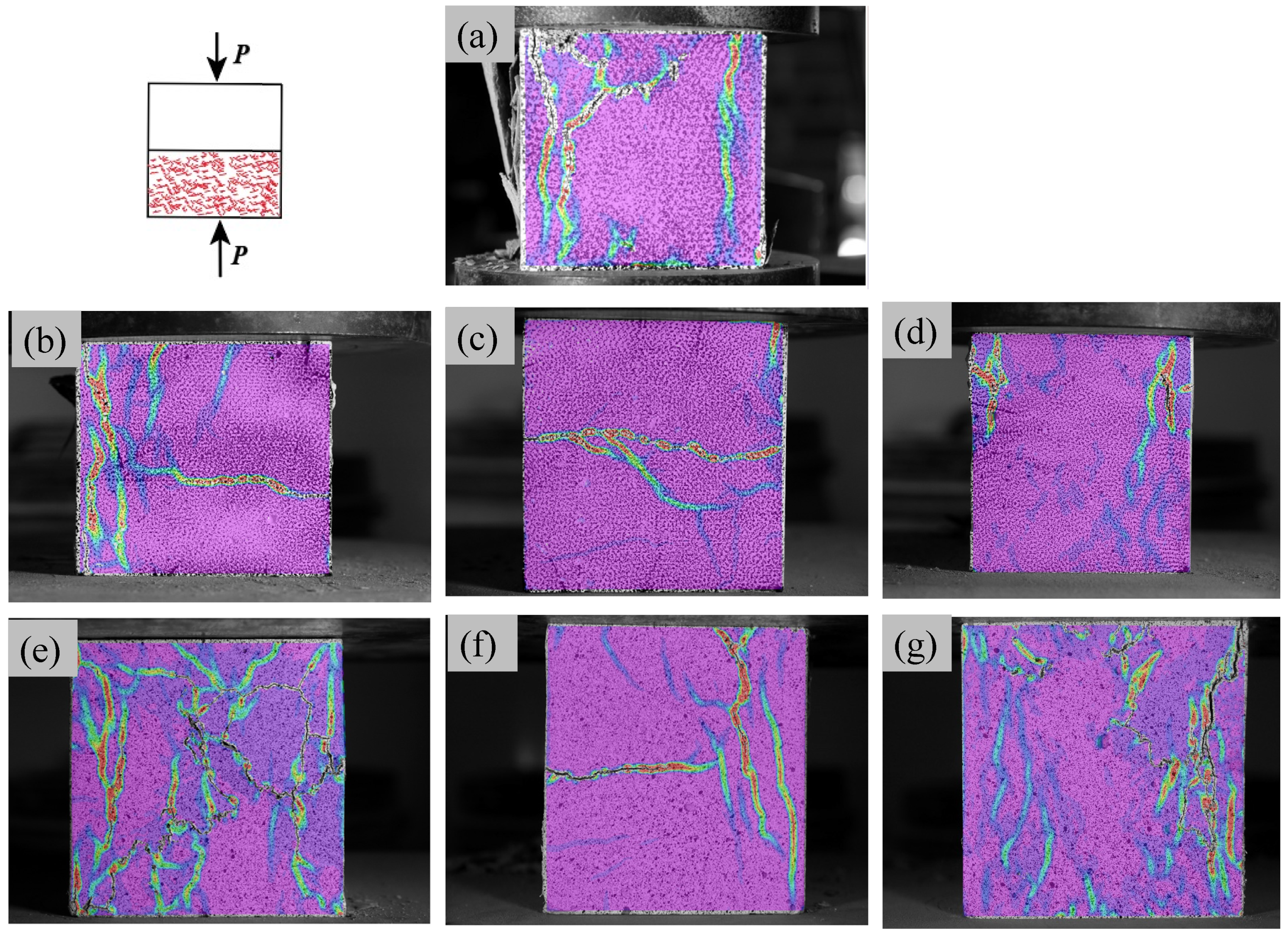
The compression failure process captured for the non-fiber-reinforced concrete, steel fiber-reinforced, and polyethylene (PE) fiber-reinforced concrete blocks showed a stark contrast in terms of the behavior of these materials under high-stress conditions, as shown in Figure 12. Analyzing the DIC images, one could observe that in the non-fiber-reinforced concrete specimens, the failure was characterized by a significant crack width. As the specimens reached the failure point, large concrete chunks were ejected from the block’s periphery, indicative of a brittle fracture. This failure mode, typical in plain concrete, suggested a rapid release of energy with little prior indication of impending rupture.

Figure 12.
Compressive cracking: (a) 00, (b) S25, (c) S50, (d) S75, (e) P25, (f) P50, and (g) P75.
In contrast, the addition of fibers, both steel and PE, transformed the failure characteristics dramatically. The fiber-reinforced specimens did not exhibit the violent expulsion of fragments upon reaching peak compressive strength, a substantial improvement over the non-fiber-reinforced specimens. The cracks that appeared were narrower, showing that fibers within the concrete matrix provided a restraining force against the propagation of cracks. The steel fiber-reinforced concrete blocks, when subjected to compressive forces, displayed fewer cracks around the interface areas. The steel fibers across these regions likely inhibited crack formation and propagation, contributing to a more contained failure. This observation aligned with the known properties of steel fibers, which provide high tensile strength and stiffness to the concrete matrix, hence improving toughness. The PE fiber-reinforced concrete specimens exhibited a multi-crack characteristic upon failure, suggesting a dissipation of stress across multiple planes within the material. These multiple fine cracks were indicative of a more ductile failure mechanism, where the PE fibers allowed the concrete matrix to deform more before reaching the failure point. Consequently, the PE fiber specimens’ interface compressive peak strength was notably higher than that of the steel fiber specimens. This indicated that PE fibers contributed to a more even distribution of compressive stress at the interface, thus enhancing the overall compressive strength of the fiber interface.
Table 4 provides a comprehensive overview of the average crack widths for various fiber-reinforced concrete samples under compressive loading conditions. The baseline sample (00) exhibited an average crack width of 0.45 mm. In comparison, the addition of steel fibers (S25, S50, and S75) significantly reduced the average crack width, demonstrating the effectiveness of fiber reinforcement. Specifically, the S25 sample had an average crack width of 0.35 mm, which represents a 22.22% reduction relative to the baseline. Further enhancements were observed in the S50 and S75 samples, with crack widths of 0.27 mm and 0.23 mm, corresponding to reductions of 40% and 48.89%, respectively. These results underscore the superior performance of steel fiber reinforcement in mitigating crack propagation under compressive stresses. Similarly, the polyethylene fiber-reinforced concrete samples (P25, P50, and P75) also showed improved crack resistance compared to the baseline. The P25 sample achieved an average crack width of 0.30 mm, marking a 33.33% reduction. The P50 and P75 samples exhibited crack widths of 0.28 mm and 0.21 mm, corresponding to reductions of 37.78% and 53.33%, respectively.
Table 4.
Average crack width in compressive test.
The fracture patterns postulated that PE fibers could significantly improve the force distribution characteristics of fiber-reinforced concrete interfaces. The presence of PE fibers in the concrete matrix seemed to facilitate a better performance in regions typically considered as weak points in the interface. The more uniform stress distribution reduced the likelihood of localized failure and allowed the interface to withstand greater loads. While steel fibers provided a certain degree of toughness and limited crack widths, PE fibers appeared to offer superior benefits in terms of enhancing compressive strength and inducing a more ductile, controlled failure mode. The ability of PE fibers to create a more resilient interface in concrete structures could be particularly advantageous in applications where the integrity of the interface zone is paramount.
4.3. Shear Cracking Evolution
The shear test experiments captured through Digital Image Correlation (DIC) offered profound insight into the shear failure mechanisms of concrete with varying fiber contents, as shown in Figure 13. In the non-fiber-reinforced concrete specimens, a sudden brittle fracture occurred upon reaching the peak shear load, manifested by a loud noise followed by the ejection of a block portion. This dramatic failure mode is characteristic of the brittle nature of traditional concrete, where shear forces exceeded the material’s tensile capacity, leading to abrupt fracturing.

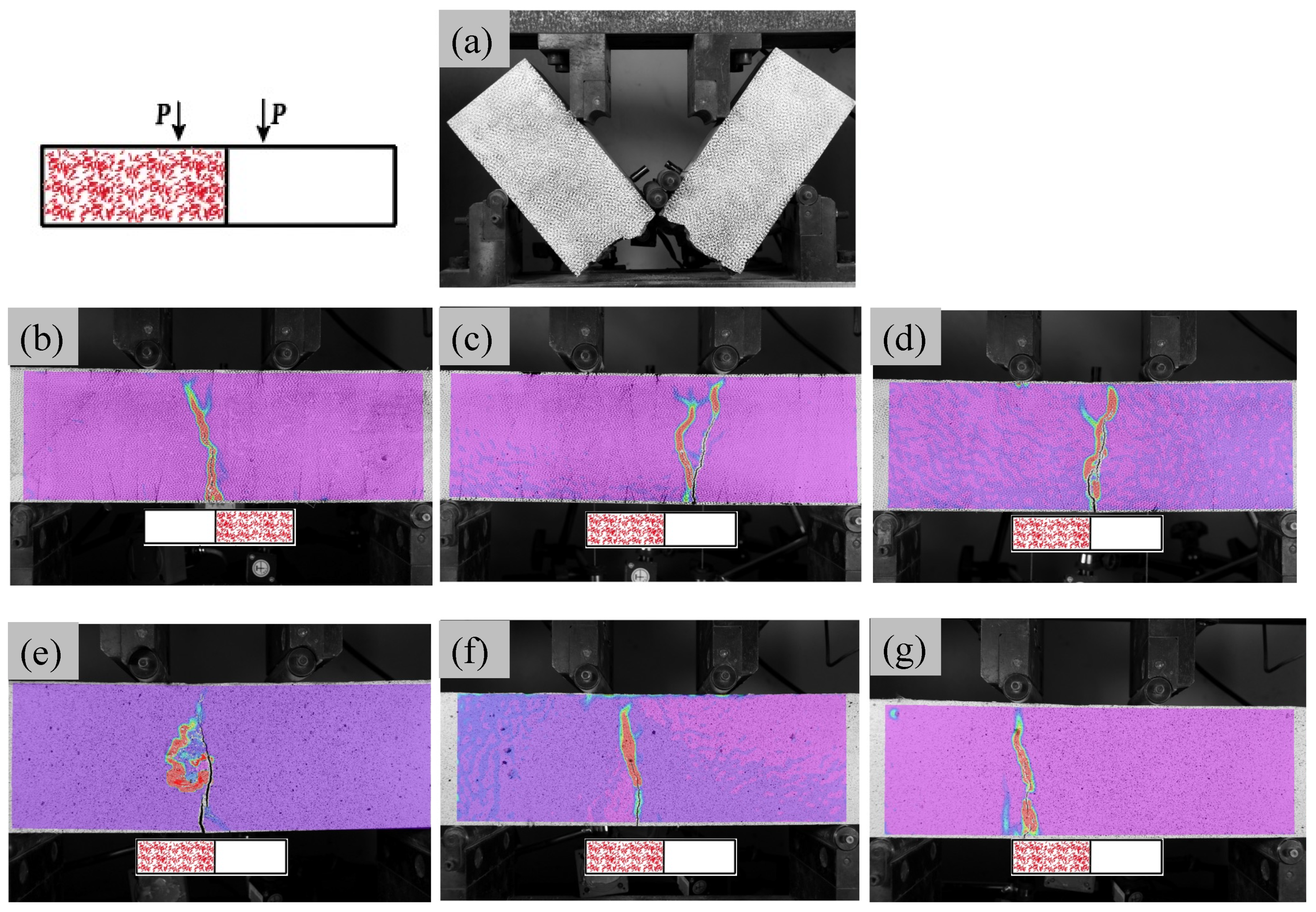
Figure 13.
Shear cracking: (a) 00, (b) S25, (c) S50, (d) S75, (e) P25, (f) P50, and (g) P75.
In the case of steel fiber-reinforced concrete, the interfacial shear failure process demonstrated a marked departure from the brittle failure observed in the non-fiber specimens. As the steel fiber volume increased from 0.25% to 0.5%, and finally to 0.75%, and the concrete no longer failed in a brittle manner. Instead, a slight reduction in crack width was observed with increasing fiber content. However, the difference in crack width between the 0.5% and 0.75% fiber volumes was minimal. This phenomenon suggested that while increasing fiber content generally reduced crack propagation, the dispersion of fibers at 0.75% might decrease due to agglomeration, thereby negating the expected reduction in crack width with a higher fiber volume.
Table 5 reveals the changes in shear performance for the various fiber-reinforced concrete samples under continuous casting conditions, as measured by the average crack width. The baseline sample (00) exhibited an average crack width of 0.55 mm. Introducing steel fibers (S25, S50, and S75) into the mix resulted in noticeable improvements. The S25 sample reduced the average crack width to 0.48 mm, a 12.73% reduction compared to the baseline. More substantial reductions were observed with higher fiber contents: the S50 sample exhibited an average crack width of 0.39 mm, a 29.09% reduction, and the S75 sample achieved the most significant decrease to 0.27 mm, representing a 50.91% reduction. These results underscore the effectiveness of steel fibers in enhancing the shear resistance of continuously cast concrete, with higher fiber volumes providing greater improvements. Similarly, the incorporation of polyethylene fibers (P25, P50, and P75) also enhanced the shear performance. The P25 sample showed an average crack width of 0.42 mm, translating to a 23.64% reduction compared to the baseline. The P50 sample further decreased the average crack width to 0.37 mm, achieving a 32.73% reduction. The P75 sample, with an average crack width of 0.24 mm, demonstrated the highest improvement among the polyethylene fiber-reinforced samples, corresponding to a 56.36% reduction.
Table 5.
Average crack width in shear test.
The PE fiber-reinforced concrete specimens exhibited a notable decrease in crack width, indicating a substantial improvement in the material’s resistance to shear stresses. During shear failure, multiple fine cracks appeared, as opposed to a single dominant crack. This behavior improved the shear interface’s load-bearing characteristics by allowing more fibers to engage and share the imposed shear loads. With an increase in PE fiber volume, the tendency for the development of these fine cracks diminished, suggesting an enhanced fiber–matrix interaction that distributed stresses more evenly across the concrete section.
The DIC imaging showed that the PE fiber interface exhibited superior performance compared to the steel fiber interface in terms of the failure mode. The PE fibers contributed to a more ductile failure mechanism, where the development of multiple cracks allowed the material to absorb and redistribute shear forces more effectively than steel fibers. This ductility translated into a more gradual failure process, enhancing the concrete’s overall shear capacity.
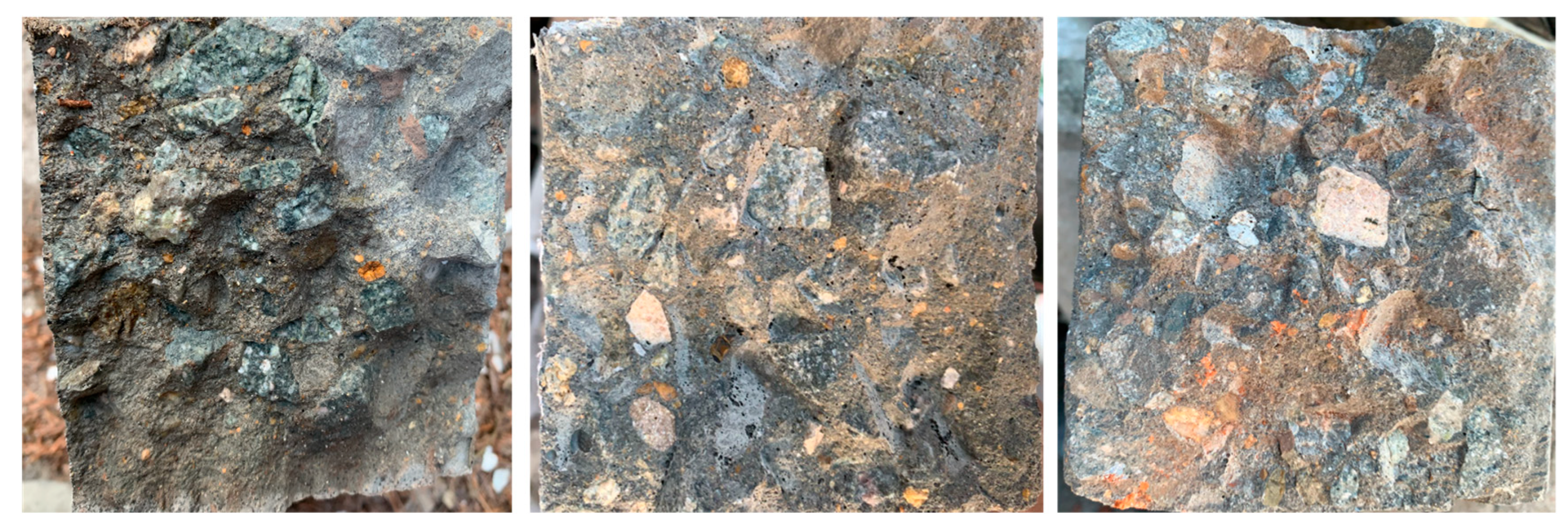
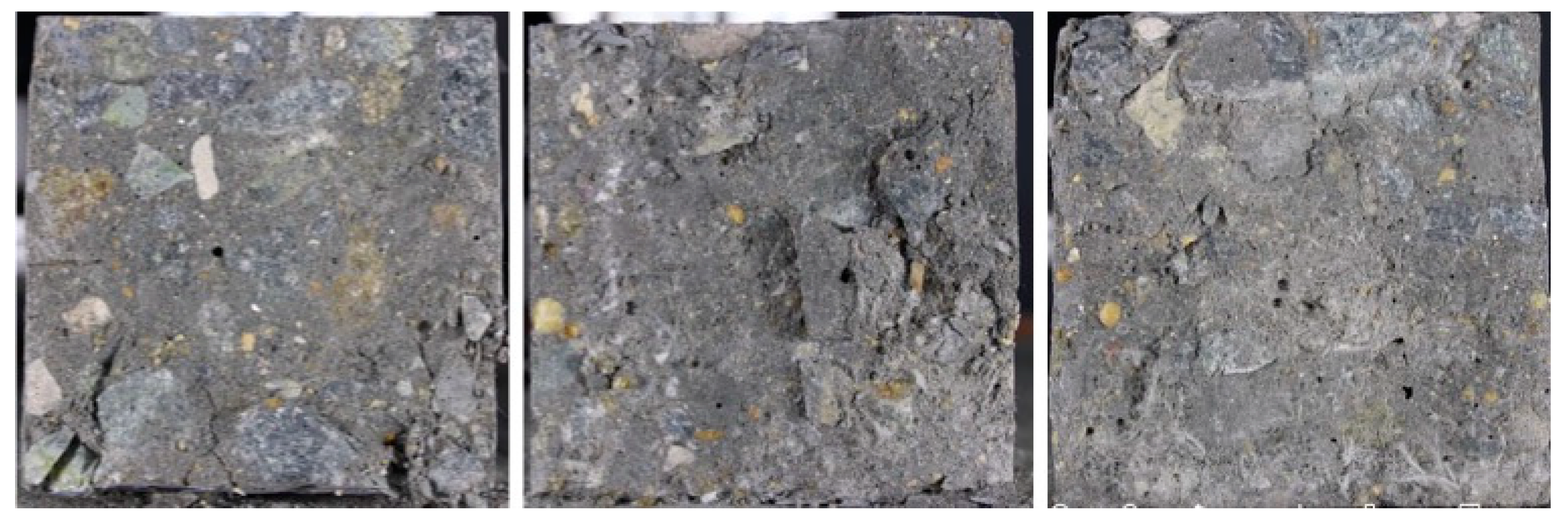
4.4. Fiber Distribution
In the analysis of the cross-sectional fiber and porosity distribution characteristics across the seven different test mixtures, distinct patterns emerged that reflected the intrinsic properties of the fibers and their interaction with the concrete matrix, as shown in Figure 14, Figure 15 and Figure 16. In the control samples devoid of fibers, the distribution of pores was consistent, a direct consequence of the well-established practices in concrete mixing and curing that aimed to minimize porosity and maximize homogeneity.

Figure 14.
Cross-sectional properties of non-fiber-reinforced concrete.
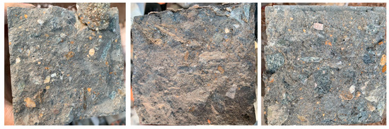
Figure 15.
Cross-sectional properties of steel fiber-reinforced concrete.

Figure 16.
Cross-sectional properties of PE fiber-reinforced concrete.
Upon the integration of steel fibers, the concrete’s internal structure underwent a transformation. In the S25 condition, steel fibers were distributed throughout the concrete matrix, affecting the compaction process. This resulted in a noticeable increase in porosity, especially around the fibers, where concrete could not fully consolidate, leading to a more heterogeneous pore distribution. In the S50 samples, the steel fibers were densely packed within the matrix. This high density altered the concrete flow and consolidation dynamics, contributing to an irregular pore distribution. The rigidity and size of the steel fibers impeded the effective closure of voids, accentuating the variability in porosity throughout the cross-section. The highest steel fiber content in the S75 samples exacerbated these effects. The fibers, crowded within the matrix, inhibited workability and could lead to an increase in trapped air and voids. Despite the potential for enhanced crack bridging and toughness due to a higher fiber content, the presence of larger voids where fibers congregated undermined the concrete’s structural integrity.
For the polyethylene (PE) fiber conditions (P25, P50, and P75), the fibers’ lightweight and flexible nature offered different advantages. The P25 samples exhibited a uniform fiber distribution with a minimal impact on porosity, as the PE fibers efficiently integrated into the concrete mix without disturbing the compaction process. As the volume of PE fibers increased in the P50 condition, the even distribution of fibers remained evident. There were small increases in porosity associated with air entrapment during mixing; however, the flexibility of PE fibers ensured overall workability, facilitating a consistent pore structure across the cross-section. In the P75 samples, where the PE fiber volume was the greatest, the fibers uniformly populated the concrete matrix. Their high aspect ratio and flexibility allowed them to occupy and bridge interstitial spaces, effectively decreasing porosity and enhancing the density of the cross-section. This enhancement in the material’s density was reflected in the improved mechanical properties, such as shear and flexural strength, validating the positive effect of PE fibers at this concentration.
The findings demonstrated that fiber type and volume were decisive factors affecting fiber distribution and porosity within the concrete matrix. Steel fibers, especially at higher volumes, led to increased porosity due to challenges in compaction. In contrast, PE fibers enhanced the homogeneity of the concrete, with their flexibility and lower density contributing to a more uniform distribution of fibers and a reduction in porosity. This optimization of fiber distribution correlated with the superior mechanical properties observed, affirming the efficacy of PE fibers in producing concrete with improved structural characteristics.
5. Conclusions
Due to financial constraints, the adoption of fiber-reinforced concrete in large-scale construction is frequently restricted. To counter this, our research investigated targeted reinforcement at essential interfaces, utilizing an innovative synchronized casting mold that diverges from traditional segmented casting interface approaches. The study focused on the bending, compressive, and shear attributes at the interface between fiber-reinforced concrete and conventional concrete produced with a continuous casting process. The key insights are as follows:
- (1)
- Fine fibers have superior anti-cracking benefits, with PE fibers demonstrating a comprehensive advantage over steel fibers in terms of flexural, compressive, and shear properties. Notably, PE fibers significantly improved the interface’s flexural strength, showcasing their exceptional performance.
- (2)
- PE fibers, due to their high elasticity modulus, tensile strength, and optimal aspect ratio, markedly enhanced the interface’s resistance to bending. They facilitated load transfer to the fiber-reinforced side, allowing the unique tensile properties of PE fiber-reinforced concrete to be fully utilized.
- (3)
- With PE fibers’ low density and better dispersion properties during mixing, they do not exhibit the sinking behavior seen with steel fibers. The larger surface area of PE fibers per volume allows for better adherence to moisture, effectively lowering the water–cement ratio and enhancing the compressive strength of the interface in comparison to steel fiber-reinforced concrete.
- (4)
- Steel fibers, due to their density, commonly experience sinking and clumping during mixing and vibrating, which negatively impacts their distribution within the concrete matrix. Consequently, steel fiber-reinforced concrete interfaces exhibited inferior shear resistance compared to non-fiber-reinforced concrete, while PE fiber interfaces showed a slight improvement in shear resistance.
- (5)
- Considering ductility requirements, a 0.75% PE fiber volume is appropriate, yet from an economic standpoint, lower volumes of 0.25% or 0.5% are recommended, provided that the fibers are well-dispersed.
Regardless of the fiber type, the dispersion of fibers is critical to the performance of composite cementitious materials. Fiber dispersion is influenced by factors including the inherent characteristics of the fiber material, the mixing process, and the particle size distribution of the matrix components. Comprehensive improvements in these areas are essential to maximize the performance benefits of fiber-reinforced concrete.
Author Contributions
M.C.: conceptualization, data curation, formal analysis, investigation, writing—original draft; H.Z.: supervision, formal analysis; T.R.: conceptualization, supervision; X.Z.: conceptualization, supervision, writing, formal analysis, funding acquisition, writing—review and editing. All authors have read and agreed to the published version of the manuscript.
Funding
The authors gratefully acknowledge projects 52278411 and 22JC14041001, which are supported by the National Natural Science Foundation of China and Shanghai Science and Technology Innovation Action.
Data Availability Statement
The original contributions presented in the study are included in the article, further inquiries can be directed to the corresponding author.
Conflicts of Interest
The authors declare that they have no known competing financial interests or personal relationships that could have appeared to influence the work reported in this paper.
References
- Afroughsabet, V.; Biolzi, L.; Ozbakkaloglu, T. High-performance fiber-reinforced concrete: A review. J. Mater. Sci. 2016, 51, 6517–6551. [Google Scholar] [CrossRef]
- Thomas, J.; Ramaswamy, A. Mechanical properties of steel fiber-reinforced concrete. J. Mater. Civ. Eng. 2007, 19, 385–392. [Google Scholar] [CrossRef]
- Xue, H.; Deng, Z.; Li, J. Tensile performance and toughness of PVA fiber reinforced cementitious composites. J. Zhengzhou Univ. Eng. Sci. 2009, 30, 92–95. [Google Scholar]
- Wang, Z.; Fei, J.; Ma, W.; Chen, X. Full-scale loading experiments on performance of UHPC joints for prefabricated mountain tunnel. Tunn. Undergr. Space Technol. 2023, 131, 104784. [Google Scholar] [CrossRef]
- Ye, J.; Cui, C.; Yu, J.; Yu, K.; Dong, F. Effect of polyethylene fiber content on workability and mechanical-anisotropic properties of 3D printed ultra-high ductile concrete. Constr. Build. Mater. 2021, 281, 122586. [Google Scholar] [CrossRef]
- Ye, J.; Cui, C.; Yu, J.; Yu, K.; Xiao, J. Fresh and anisotropic-mechanical properties of 3D printable ultra-high ductile concrete with crumb rubber. Compos. Part B Eng. 2021, 211, 108639. [Google Scholar] [CrossRef]
- Yu, J.; Dong, F.; Ye, J. Experimental study on the size effect of ultra-high ductile cementitious composites. Constr. Build. Mater. 2020, 240, 117963. [Google Scholar] [CrossRef]
- Zhang, X.; Zhang, W.; Luo, Y.; Wang, L.; Peng, J.; Zhang, J. Interface shear strength between self-compacting concrete and carbonated concrete. J. Mater. Civ. Eng. 2020, 32, 04020113. [Google Scholar] [CrossRef]
- Angst, U.M.; Geiker, M.R.; Alonso, M.C.; Polder, R.; Isgor, O.B.; Elsener, B.; Wong, H.; Michel, A.; Hornbostel, K.; Gehlen, C.; et al. The effect of the steel–concrete interface on chloride-induced corrosion initiation in concrete: A critical review by RILEMTC, 2.6.2.-S.C.I. Mater. Struct. 2019, 52, 88. [Google Scholar] [CrossRef]
- Angst, U.M.; Geiker, M.R.; Michel, A.; Gehlen, C.; Wong, H.; Isgor, O.B.; Elsener, B.; Hansson, C.M.; François, R.; Hornbostel, K.; et al. The steel–concrete interface. Mater. Struct. 2017, 50, 143. [Google Scholar] [CrossRef]
- Buyukozturk, O.; Hearing, B. Crack propagation in concrete composites influenced by interface fracture parameters. Int. J. Solids Struct. 1998, 35, 4055–4066. [Google Scholar] [CrossRef]
- He, Y.; Zhang, X.; Hooton, R.; Zhang, X. Effects of interface roughness and interface adhesion on new-to-old concrete bonding. Constr. Build. Mater. 2017, 151, 582–590. [Google Scholar] [CrossRef]
- Tian, J.; Jiang, X.; Yang, X.; Ma, M.; Li, L. Bonding performance of the grooved interface between ultrahigh performance concrete and normal concrete. Constr. Build. Mater. 2022, 336, 127525. [Google Scholar] [CrossRef]
- Zhu, W.; Yang, C.; Yu, Z.; Xiao, J.; Xu, Y. Impact of defects in steel-concrete interface on the corrosion-induced cracking propagation of the reinforced concrete. KSCE J. Civ. Eng. 2023, 27, 2621–2628. [Google Scholar] [CrossRef]
- Feng, S.; Xiao, H.; Liu, M.; Zhang, F.; Lu, M. Shear behaviour of interface between normal-strength concrete and UHPC: Experiment and predictive model. Constr. Build. Mater. 2022, 342, 127919. [Google Scholar] [CrossRef]
- Huang, Y. Three-dimensional numerical investigation of mixed-mode debonding of FRP-concrete interface using a cohesive zone model. Constr. Build. Mater. 2022, 350, 128818. [Google Scholar]
- Tayeh, B.A.; Bakar, B.A.; Johari, M.M.; Voo, Y.L. Mechanical and permeability properties of the interface between normal concrete substrate and ultra high performance fiber concrete overlay. Constr. Build. Mater. 2012, 36, 538–548. [Google Scholar] [CrossRef]
- Vervuurt, A.H.J.M. Interface Fracture in Concrete. Ph.D. Thesis, Delft University of Technology, Delft, The Netherlands, 1997. [Google Scholar]
- Zhang, Y.; Zhu, P.; Wang, X.; Wu, J. Shear properties of the interface between ultra-high performance concrete and normal strength concrete. Constr. Build. Mater. 2020, 248, 118455. [Google Scholar] [CrossRef]
- Prado, L.P.; Carrazedo, R.; El Debs, M.K. Interface strength of high-strength concrete to ultra-high-performance concrete. Eng. Struct. 2022, 252, 113591. [Google Scholar] [CrossRef]
- Qian, P.; Xu, Q. Experimental investigation on properties of interface between concrete layers. Constr. Build. Mater. 2018, 174, 120–129. [Google Scholar] [CrossRef]
- Santos, D.S.; Santos, P.M.; Dias-da-Costa, D. Effect of surface preparation and bonding agent on the concrete-to-concrete interface strength. Constr. Build. Mater. 2012, 37, 102–110. [Google Scholar] [CrossRef]
- Shah, S.G.; Chandra Kishen, J. Fracture properties of concrete–concrete interfaces using digital image correlation. Exp. Mech. 2011, 51, 303–313. [Google Scholar] [CrossRef]
- Tayeh, B.A.; Bakar, B.A.; Johari, M. Mechanical properties of old concrete-UHPFC interface. In Proceedings of the International Conference on Concrete Repair, Rehabilitation and Retrofitting, Cape Town, South Africa, 3–5 September 2012; p. 02-5. [Google Scholar]
- Afandi, M.E.; Yehia, S.; Landolsi, T.; Qaddoumi, N.; Elchalakani, M. Concrete-to-concrete bond Strength: A review. Constr. Build. Mater. 2023, 363, 129820. [Google Scholar] [CrossRef]
- Daneshvar, D.; Behnood, A.; Robisson, A. Interfacial bond in concrete-to-concrete composites: A review. Constr. Build. Mater. 2022, 359, 129195. [Google Scholar] [CrossRef]
- Ju, Y.; Shen, T.; Wang, D. Bonding behavior between reactive powder concrete and normal strength concrete. Constr. Build. Mater. 2020, 242, 118024. [Google Scholar] [CrossRef]
- Leone, M.; Centonze, G.; Colonna, D.; Micelli, F.; Aiello, M. Fiber-reinforced concrete with low content of recycled steel fiber: Shear behaviour. Constr. Build. Mater. 2018, 161, 141–155. [Google Scholar] [CrossRef]
- Ahmad, J.; González-Lezcano, R.A.; Majdi, A.; Ben Kahla, N.; Deifalla, A.F.; El-Shorbagy, M.A. Glass fibers reinforced concrete: Overview on mechanical, durability and microstructure analysis. Materials 2022, 15, 5111. [Google Scholar] [CrossRef]
- GB/T 50081–2002; Standard for Test Method of Mechanical Properties on Ordinary Concrete. Standards Press of China: Beijing, China, 2003. (In Chinese)


Disclaimer/Publisher’s Note: The statements, opinions and data contained in all publications are solely those of the individual author(s) and contributor(s) and not of MDPI and/or the editor(s). MDPI and/or the editor(s) disclaim responsibility for any injury to people or property resulting from any ideas, methods, instructions or products referred to in the content. |
© 2024 by the authors. Licensee MDPI, Basel, Switzerland. This article is an open access article distributed under the terms and conditions of the Creative Commons Attribution (CC BY) license (https://creativecommons.org/licenses/by/4.0/).