Article

An Approach of BIM-Based Dynamic Adaptive Zoning for Group Piles Construction Multi-Work Areas

1
China Construction Third Bureau First Engineering Co., Ltd., Wuhan 430040, China
2
School of Traffic and Transportation, Shijiazhuang Tiedao University, Shijiazhuang 050043, China
3
Hebei Key Laboratory of Traffic Safety and Control, Shijiazhuang 050043, China
4
School of Civil Engineering and Architecture, Wuhan University of Technology, Wuhan 430070, China
*
Authors to whom correspondence should be addressed.
Buildings 2024, 14(7), 2071; https://doi.org/10.3390/buildings14072071
Submission received: 16 May 2024 / Revised: 19 June 2024 / Accepted: 3 July 2024 / Published: 7 July 2024
(This article belongs to the Section Construction Management, and Computers & Digitization)

Abstract

:
In large-scale pile foundation drilling projects, the absence of digital work area management hampers dynamic construction management, affecting efficiency. This article explores multi-work area management during pile foundation drilling using a BIM parameterized model, focusing on informatization. The results indicate the following: (i) A dynamic zoning method for pile foundation construction using BIM models was developed to support information management systems and address resource allocation challenges amid dynamic construction team changes. (ii) Adaptive zoning methods were proposed, incorporating the dynamic adjustment of construction work areas, including the division of virtual work areas and adaptive adjustment of pile foundation partition parameters. (iii) Work area modeling and zoning were applied on site, with pile foundation modeling aligning with engineering design distribution, and work area zoning accurately reflecting the on-site construction status. (iv) This method enables adaptive synchronization between pile foundation model attributes and work area information, integrating zoning management into the information system to enhance the construction unit’s information management system and digital management level.

1. Introduction

With the acceleration of urbanization worldwide, the need for the large-scale construction of urban infrastructures is rapidly increasing, which leads to the number and scale of piling works being increased dramatically for a big challenge if still applying traditional construction management. However, the construction industry has huge potential for the integration of digital technologies [1]. Construction contractors frequently adopt a division of work area method to alleviate the pressure of the project schedule and improve the efficiency of construction operations, that is, to divide the current overall pile foundation project into areas and form several construction work areas for synchronous operations. In the actual construction process on site, it is inevitable to encounter a variety of complex situations. For example, a change in the construction program or the adjustment of the construction team will change the original scope of the work area. However, the traditional zoning method has poor accuracy and low efficiency. It is necessary to combine Building Information Modeling (BIM) and related technologies for intelligent zoning, which is recommended mode by governments like that of China for the advanced management of the construction industry [2,3].
Different scholars have proposed various methods and technological applications in the field of the digital management of pile foundation construction. The methods involved include combining Revit with Dynamo visual programming and tool command languages to achieve automated modeling [4,5]. A comprehensive pile foundation construction progress tracking framework based on computer vision integrates actual progress and differential progress into a streamlined BIM using the grid mapping method, thereby achieving the progress management of pile foundation construction [6,7,8,9,10]. In large-scale pile foundation construction, multiple construction teams are usually required to carry out the construction simultaneously. A working mechanism that combines BIM technology with a collaborative platform automation system has been proposed [11]. Its precise integration of multi-source data can divide the work area in the system [12,13,14]. During construction, a digital system was created to manage pile foundation construction based on actual geological conditions and monitoring data [10,11,15,16,17], predicting the existing properties and future development direction of pile foundations [18,19]. Applying BIM technology to four-dimensional visual dynamic construction simulation enabled the effective integration of 3D models with project construction progress file data and provided a new method for engineering management [12,14]. The above scholars have used different algorithms and combined them with BIM models to plan the construction site of pile foundations reasonably when facing the problem of pile foundation construction management.
However, during the on-site construction process, uncertainties may arise, such as the need to increase the size of the construction team to meet the construction schedule and improve efficiency. These uncertainties necessitate dynamic adjustments to the initial zoning. Previous research on the digital management of pile foundation construction has been limited in providing detailed explanations of digital dynamic zoning methods. This paper explores parameterized construction technology for pile group BIM models and integrates next-generation information technologies, such as BIM and computer algorithms, with existing pile foundation construction management methods. An adaptive zoning scheme based on the dynamic adjustment of construction work areas was proposed. This scheme utilizes virtual work area division and interaction, component spatial relationship calculation, and the establishment of zoning databases to achieve digital BIM integration. By connecting the model with data from the pile foundation construction site and enabling dynamic zoning of the work area, the approach aims to enhance the digital management of pile foundation engineering construction from the perspective of pile foundation management.

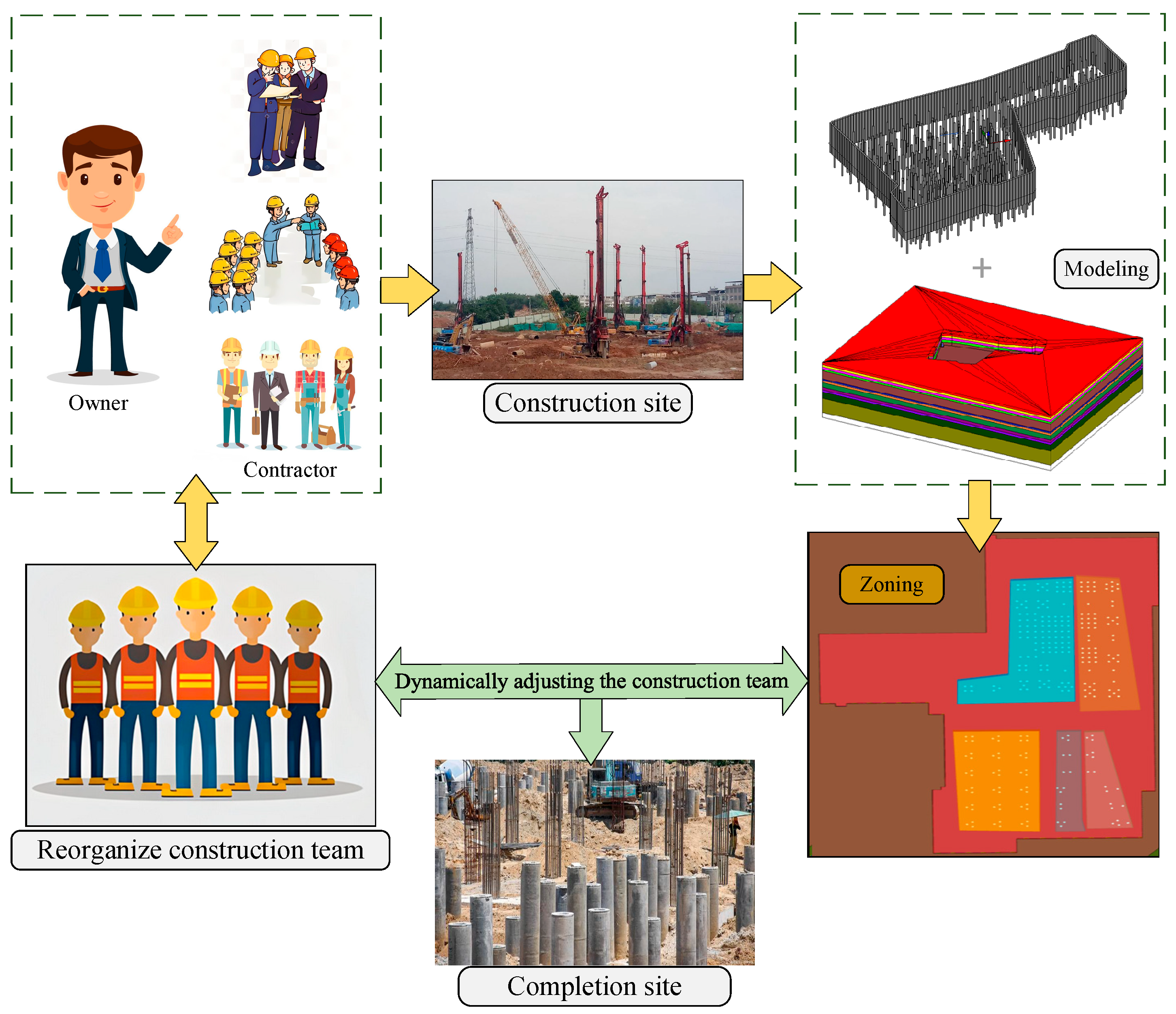
2. Requirements and Objectives of BIM-Based Zoning on Group Piles Construction Sites

The existing literature on the information management of pile foundation construction has less research on digital zoning, which cannot effectively support the construction of information management systems for pile foundation construction. When there is a dynamic increase or decrease in the construction team on the construction site, to allocate and utilize construction resources reasonably, the corresponding initial zoning needs to be dynamically adjusted.
To meet these demands, the research objective of this article is to construct a dynamic zoning and adjustment method for pile foundation construction zones based on BIM models, support the construction of an information management system for pile foundation construction, and carry out case implementation and verification. The requirements and objectives of the piling construction site are shown in Figure 1. In this figure, some of the images are sourced from the internet.

3. Implementation Processing and Method

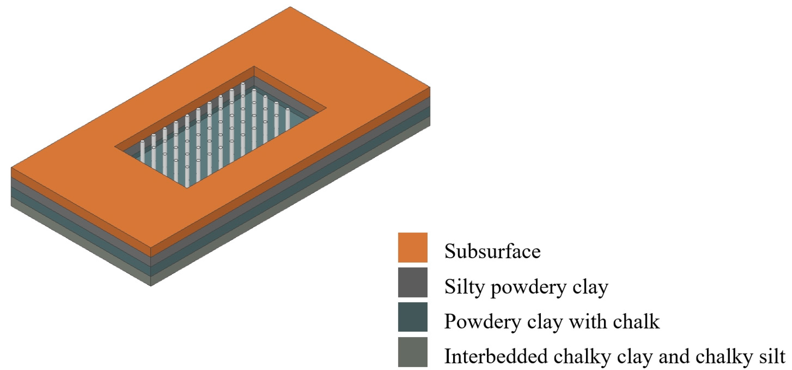
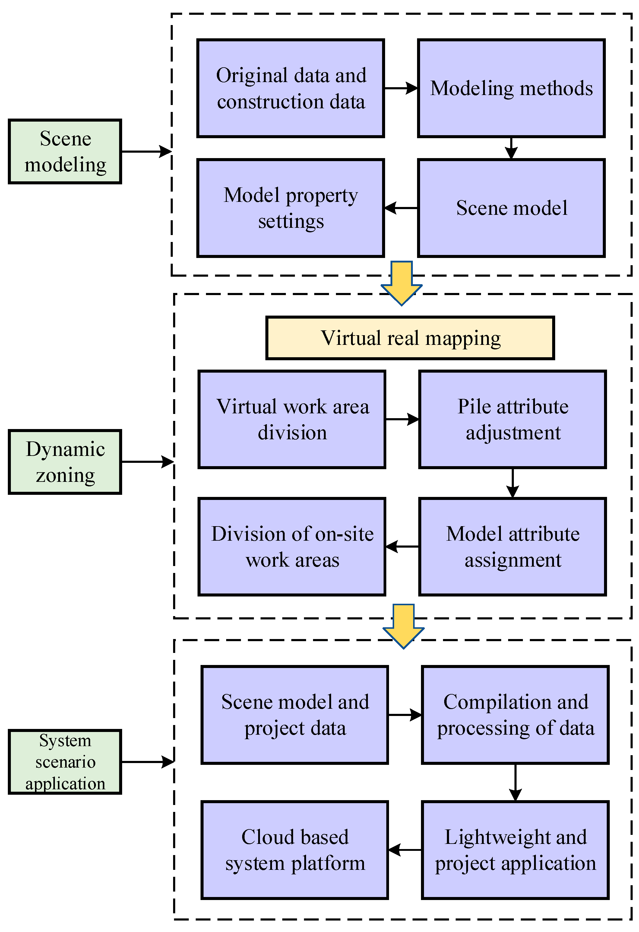
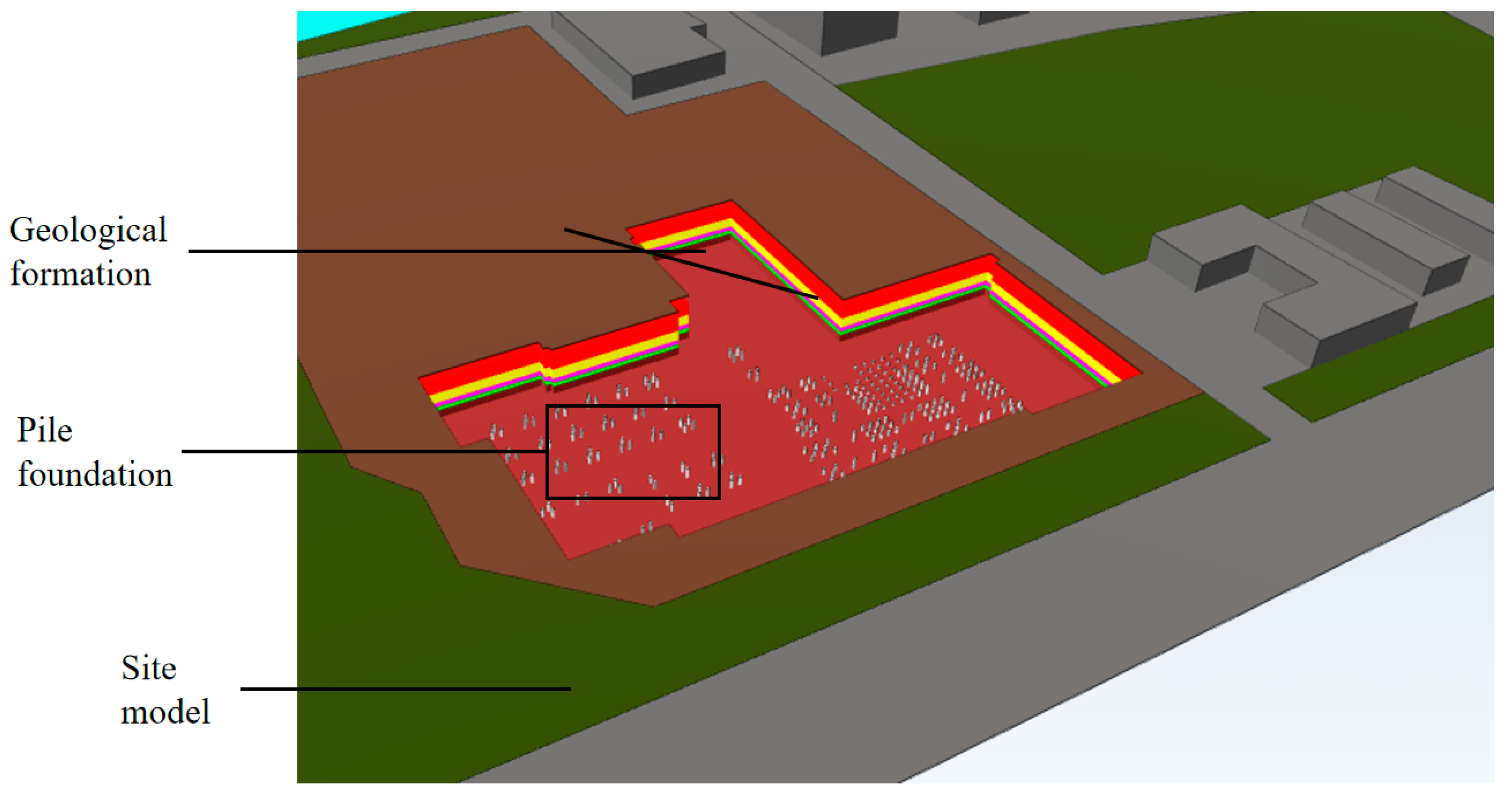
3.1. Scenario Modeling

This paper studies the establishment of a BIM model using a combination of Civil3D, Revit, and Dynamo. The modeling process is divided into three steps: model organization structure division, model attribute parameter setting, and Dynamo modeling. The modeling data of the pile foundation model comes from the construction design drawings, and the modeling data of the geological model is from the drilling data obtained by geological survey personnel by sampling the geological body in the construction area. The schematic of the scene model is shown in Figure 2.

3.1.1. Model Structure

The models are divided into three categories based on the first-level family category: environment, structural foundation, and site, corresponding to geological models, pile foundation models, and construction scene models, respectively. Among them, the environment is used to store the organizational stratigraphic model, and the family types and subtypes are uniformly named according to the stratigraphic name; structural foundations are used to store organizational pile foundation models, and the family types are divided into two categories: retaining piles and engineering piles. The subtypes of retaining pile families are set according to actual situations, such as cast-in-place piles and high-pressure spray piles; the subtypes of engineering pile families are divided into cast-in-place piles, prestressed pipe piles, etc., according to common types, and their subtypes correspond to pile foundation instances. The site is used to store ground equipment and other models that need to be expressed during on-site construction, such as roads and urban buildings, temporary facilities, etc. Its family type is set according to the “ground environment”. The organizational structure of the overall BIM model in Revit is shown in Table 1.

3.1.2. Dynamo Modeling

We created an automatic modeling logic model using Dynamo, which is called Filem Path, Select Model Element, Element Geometry, and Family Instance. The operation sequence was composed of nodes such as ByPoint. By reading the parameterized data of various attribute fields in Excel, the modeling of pile foundation groups and geological layers was automatically completed in Revit.
Firstly, the parameter types were identified, and the data were imported into Dynamo by reading the Excel table of pile foundation parameters. The pile foundation family was then laid out through the core node FamilyInstance.ByCoordinates, specifying the type of family to which the parameters would be applied and the coordinate position of the pile foundation. Next, the pile foundation parameters were set, and relevant attribute parameters were added using the Element.SetParameterByName node. After verifying the correctness of the node flow, Dynamo was run to achieve automatic modeling. Dynamo interconnected multiple nodes to form a workflow. Its key components involved laying out the staking family via the core node FamilyInstance.ByCoordinates and specifying the type of family to which the parameters are applied, as well as the coordinate location of the staking. The pile foundation parameters were then set, with relevant attribute parameters added via the Element.SetParameterByName node.

3.2. Model Attribute Parameter Setting

To achieve the association between the pile foundation model and the work areas, attribute parameters were set in the pile foundation model, and data were used as media to establish the connection between model components and the work area. The partial attribute parameter list of the pile foundation is shown in Table 2.

3.3. Adaptive Zoning Method Based on Dynamic Adjustment of Construction Work Zones

The main steps used to realize the adaptive adjustment of the piling work zone parameters on the website model were as follows:
(i)
Establish a virtual work area division method and interaction mode. Synchronize and edit the on-site work area within the virtual space for visualization processing.
(ii)
Use projection transformation to reduce the dimensionality of the 3D model, forming an editable planar view. In this view, employ the Non-Zero Winding Number algorithm to determine the positional relationship between pile points and partitions within the partition area (planar polygon).
(iii)
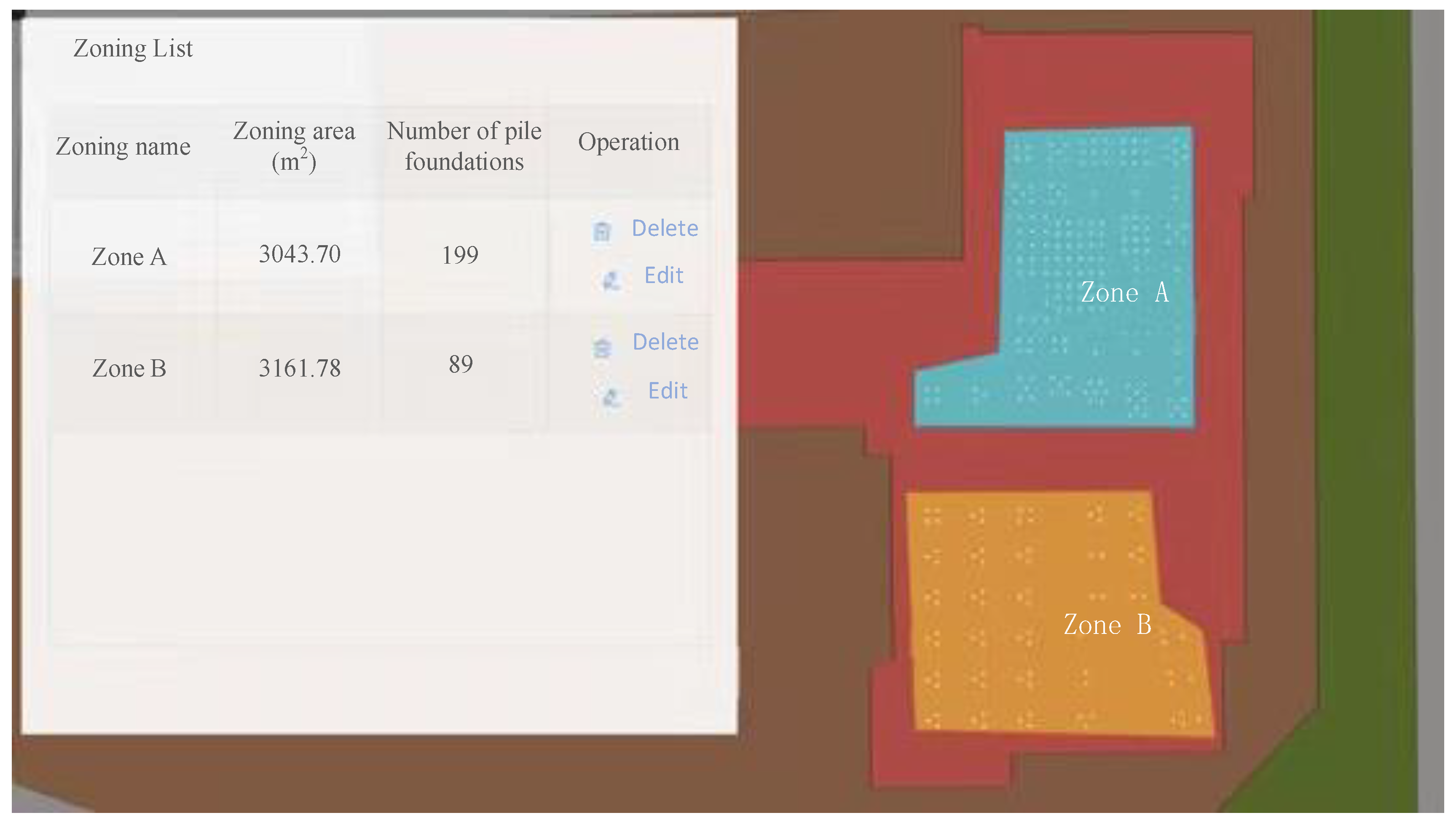
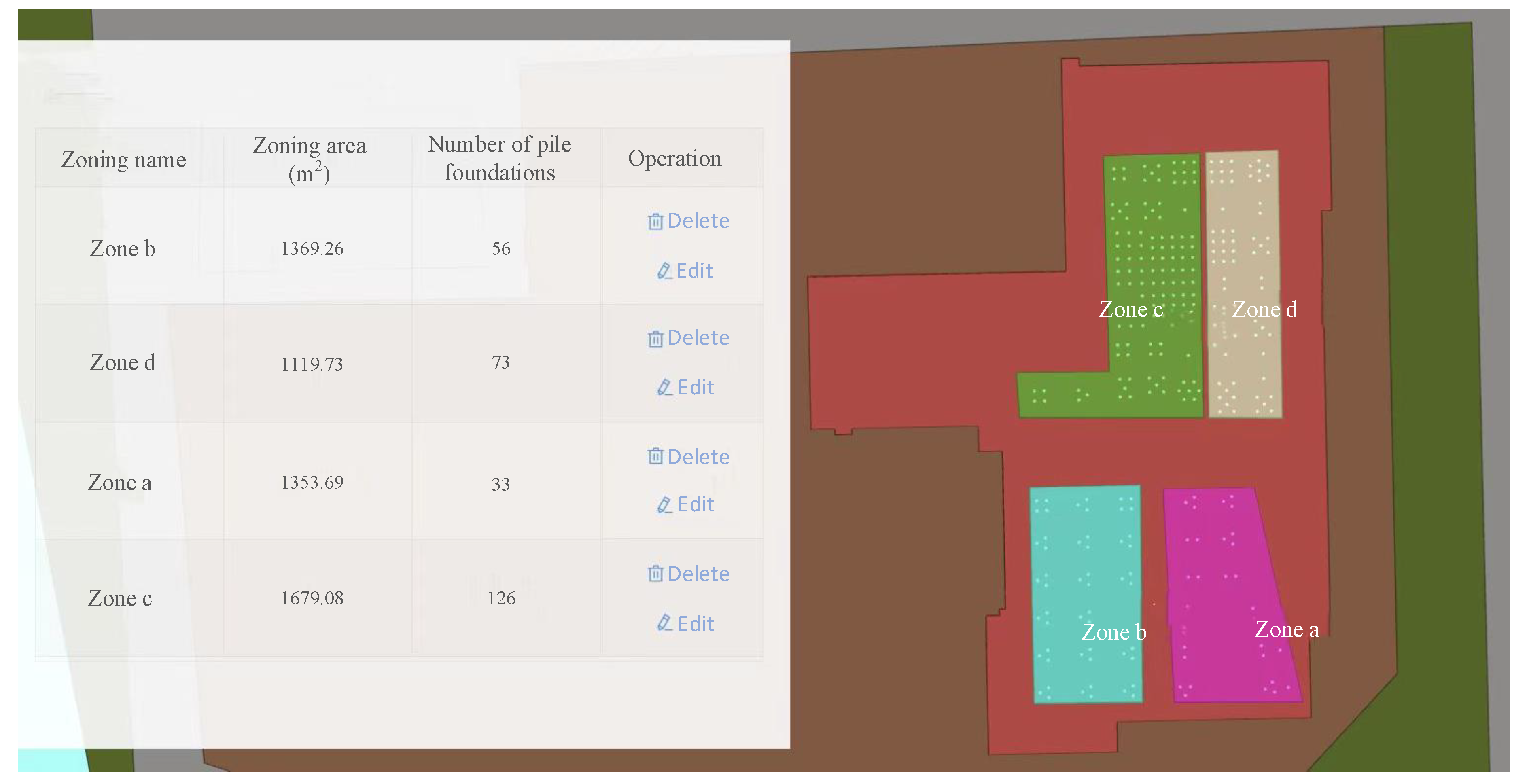
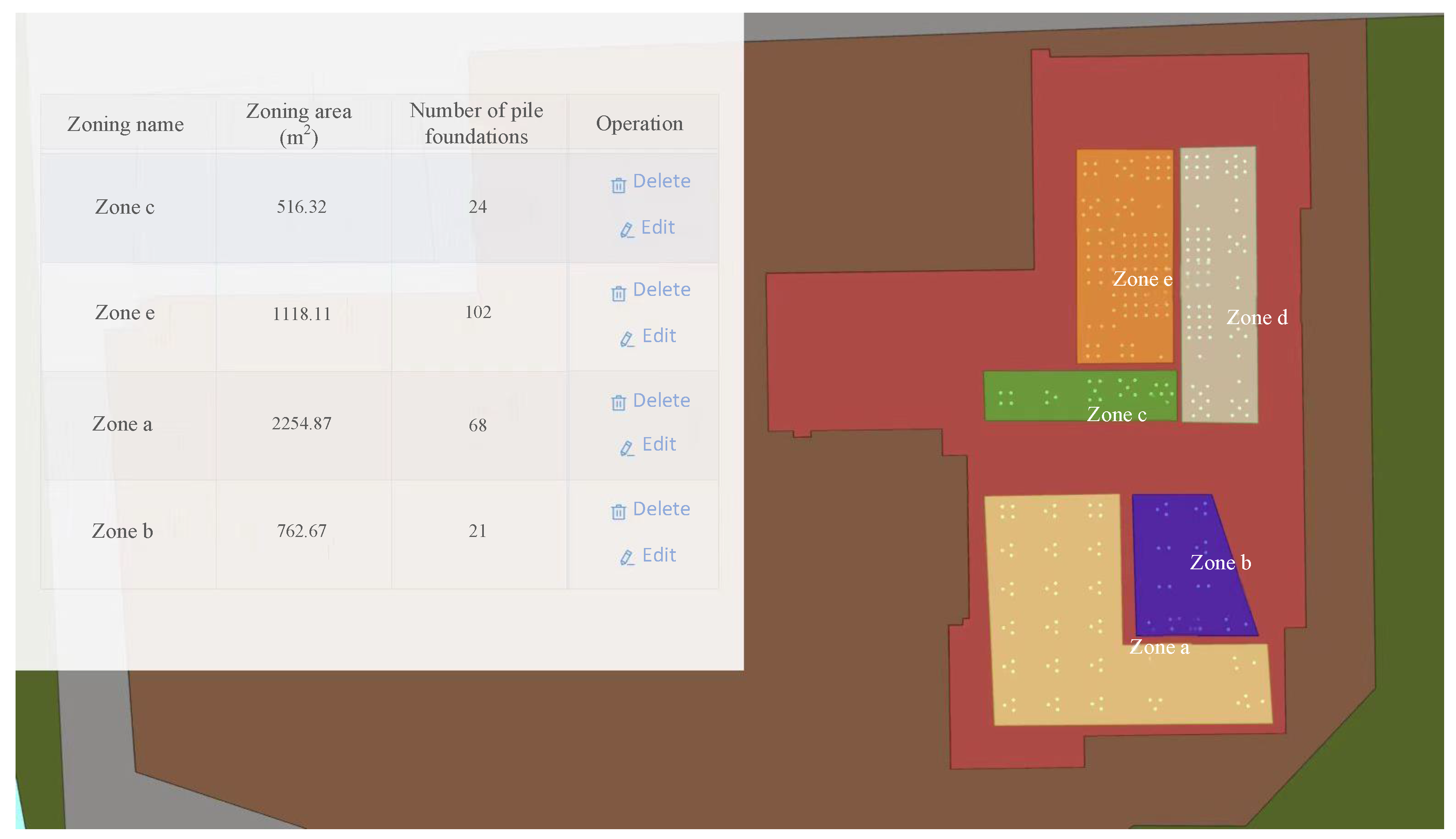
Establish a correlation between pile numbers and work areas based on the intersection relationship between pile foundations and virtual work areas. This enables on-site work area adjustments and adaptive adjustments of internal pile numbers. Figure 3a represents the initial zone, and Figure 3b represents the adjusted zone.

3.3.1. Virtual Workspace Division and Interaction

The on-site work area used latitude and longitude coordinates, while the virtual space used engineering coordinates. The conversion principle between latitude and longitude coordinates and engineering coordinates involved a seven-parameter transformation based on the reference ellipsoid WGS84 coordinate system. This transformation included rotation, translation, and scaling between the two spatial coordinate systems, producing the necessary seven parameters. Translation involved three variables: Dx, Dy, and Dz. Rotation involved three variables as well, and there was an additional scaling factor. These transformations converted a spatial coordinate system into the required target coordinate system. The seven-parameter transformation process is illustrated in Figure 4.
Creating interactive zones mainly applies the principles of graphics and is based on lightweight BIM models. By using orthographic projection transformation to place the model in the front view, interactive point selection was added to the graphic bounding box. The pile foundation components inside the bounding box were calculated and filtered through component spatial relationships, and different attributes were assigned to the bounding box to complete zone creation. It involved various basic algorithms such as view transformation, graphic interaction, graphic bounding boxes, and component spatial relationship calculation.
The zoning operation required it to be carried out in the 3D space of the web-based model. To facilitate the zoning operation, the perspective projection model needed to be transformed into a view first. The main principle of its algorithm was the geometric transformation algorithm in graphics. The basic forms of three-dimensional transformation are translation, scaling, rotation, and displacement. In practical modeling, it is necessary to deal with the combination of several transformations that exist simultaneously. In interactive computer graphics, homogeneous coordinate technology is commonly used. The homogeneous coordinate system adds a coordinate axis W to the XYZ three-dimensional coordinate system. The point P (x, y, z) in a three-dimensional coordinate system is represented by a quadruple P (x, y, z, w) in a homogeneous coordinate system.
By transforming the view, the model was set as a parallel projection top view, and then using a graphics engine mouse interactive point selection method, we added boundary polygons through point selection. The set of drawn points was the set of partition boundary points. Based on the elevation of the bottom and top of the model, we expanded to form a polygonal bounding box for spatial relationship calculation.

3.3.2. The Calculation of the Spatial Relationship of Components

The calculation of component spatial relationships mainly involved the calculation of the central local coordinates of the BIM model pile foundation components, the transformation of the global coordinates of the overall model, and the determination of the bounding box to which the components belong.
Obtain the center point coordinates of pile foundation components; pick up all vertex coordinates for pile foundation components; select the minimum and maximum values for x, y, and z coordinates, respectively; obtain the minimum and maximum coordinates of a single pile foundation component; determine the spatial range of the component; and then pick up to obtain the center point. If the coordinates of the model components needed to be converted to the overall coordinate system of the scene, this also needed to be achieved through local and global coordinate rotation transformation. In computer graphics, this is mainly achieved by rotating around three coordinate axes at a certain angle to achieve the coincidence of points corresponding to two coordinate systems. Assuming that the local coordinate system was rotated counterclockwise around the X-axis, Y-axis, and Z-axis in turn, the points corresponding to the two coordinate systems would coincide with the overall coordinate system θ 1 , θ 2 , θ 3 ; then, the points (X, Y, Z) in the local coordinate system and the corresponding points in the global coordinate system ( X , Y , Z ) in the local coordinate system, as well as the corresponding point in the global coordinate system, would be transformed, as shown in Equation (1):
X Y Z = cos θ 3 sin θ 3 0 sin θ 3 cos θ 3 0 0 0 1 cos θ 2 0 sin θ 2 0 1 0 sin θ 2 0 cos θ 2 1 0 0 0 cos θ 1 sin θ 1 0 sin θ 1 cos θ 1 X Y Z  
For two spatial coordinate systems with translation transformations, first, solve for the offsets Δ X , Δ Y , Δ Z ; then, the transformation between the point (X, Y, Z) in the local coordinate system and the corresponding point ( X , Y , Z ) in the global coordinate system exists, as shown in Equation (2):
X Y Z = X Y Z Δ X Δ Y Δ Z  
Combining the above spatial transformation scenarios, the final transformation can be carried out via matrix transformation, as shown in Equation (3):
X Y Z = cos θ 3 sin θ 3 0 sin θ 3 cos θ 3 0 0 0 1 cos θ 2 0 sin θ 2 0 1 0 sin θ 2 0 cos θ 2 1 0 0 0 cos θ 1 sin θ 1 0 sin θ 1 cos θ 1 X Y Z Δ X Δ Y Δ Z
Complete the conversion of points in the local coordinate system to the overall coordinate system.
Through the above spatial coordinate transformation, the planarization of the 3D model was achieved, simplifying the calculation of 3D spatial relationships to determine whether a point is located within a closed path (such as a polygon). The Non-Zero Winding Number algorithm was used to determine the positional relationship between a given point and a closed path by calculating the number of rotations of the closed path around the given point.
Assuming that the vertices of an irregular polygon are V1, V2, …, Vn, Vi with coordinates (xi, yi), and the point to be determined is O (xo, yo), perform angle calculation, as shown in Equations (4) and (5):
θ i = arctan 2 ( y i y O , x i x O )
θ i + 1 = arctan 2 ( y i + 1 y O , x i + 1 x O )
Calculate the number W by summing up the difference in angles between adjacent vertices, as shown in Equation (6):
W = 1 2 π i = 1 n   ( θ i + 1 θ i )
Among them, the order Δ θ = θ i + 1 θ i needs to ensure that Δ θ is the shortest angle change, that is, the interval range is π , π .
Finally, the positioning of point O was determined based on the value of the number of turns W: if W = 0, it was inferred that point O was located outside the closed path; on the contrary, if W was not 0, it was inferred that point O is located inside the closed path. Using this method, traverse the relative positions of all pile foundation point coordinates and the work area (i.e., planar polygon) area. Subsequently, the pile foundation points located within each work area were assigned corresponding zone name attributes to accurately obtain zone information for all pile foundation points.

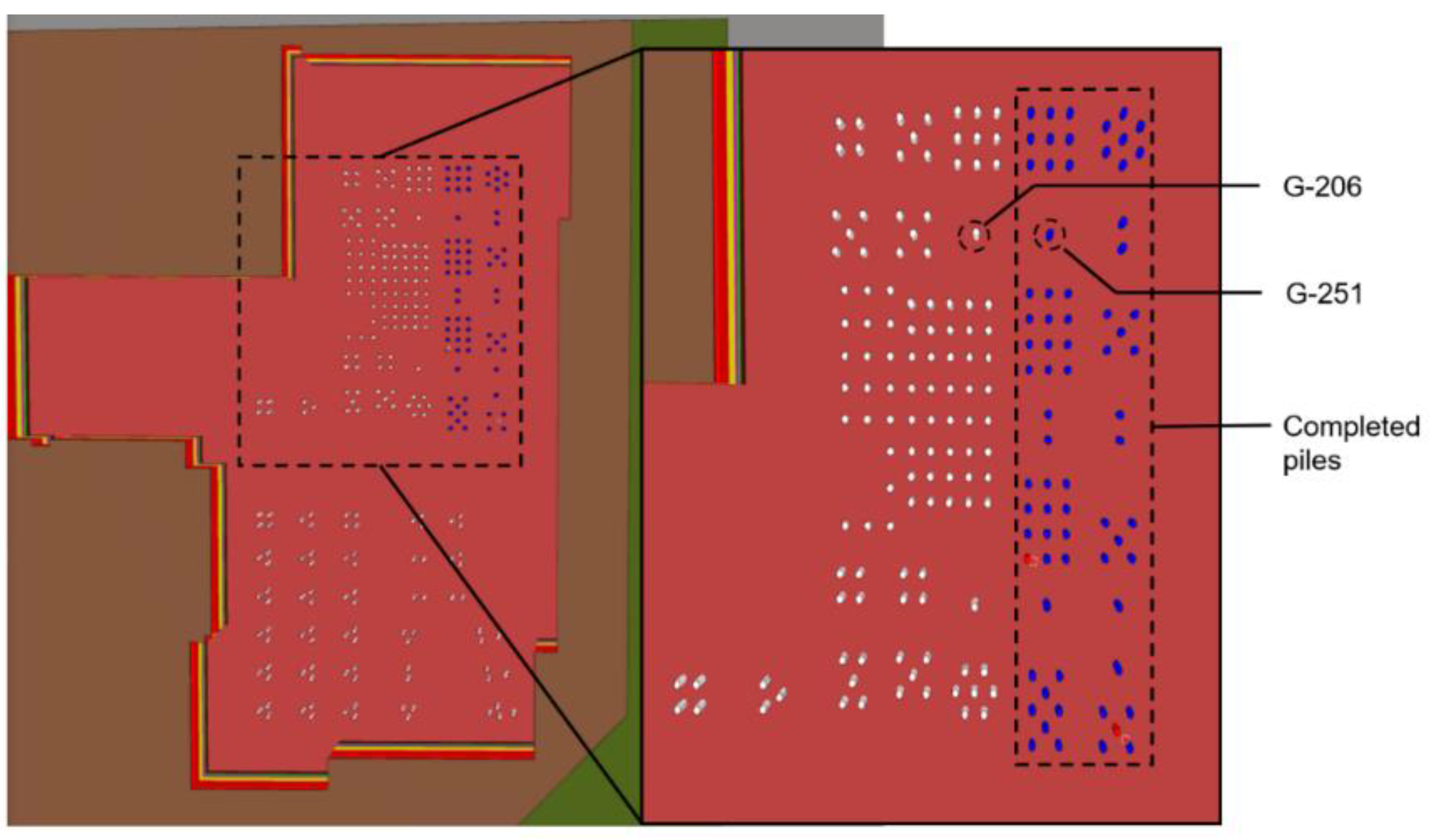
3.3.3. Piling Zoning Database Construction

The information on the construction site’s work area was stored and transmitted through the establishment of a data collection database. Based on the judgment method of the spatial relationship of the above components and the association with the BIM model items, the database association method was used to achieve adaptive adjustment of the pile foundation zoning parameters. The database mainly included the project pile foundation zoning table (tb_project_pile_part) and pile foundation information table (tb_pile_info). The tb_project_pile_part table was used to record data such as zoning names, zoning boundaries, and components within the zone. The tb_pile_info table was used to record data such as component IDs, zoning IDs, and the coordinates of pile foundations.
The data structure of tb_project_pile_part is shown in Table 3, which is used to record the data collected in the field, and the data collected using the project_id and model_file_id were used to determine the object of the zoning; the part_boundary data were generated by the user manipulating the virtual zone delimitation, while part_name was derived from user naming.
The data structure of tb_pile_info is shown in Table 4 and is used to record the base parameters of the pile model.

3.4. Adaptive Adjustment of Pile Zoning Parameters

The adaptive adjustment of pile foundation partition parameters was mainly achieved through JavaScript and BIMface development components to establish a system platform. The platform integrated virtual work area zoning and interaction modules and component spatial relationship calculation modules and used database association retrieval methods to read the rules of the project pile foundation partition table and pile foundation information table, ensuring that the work area and pile foundation model had matching correspondence.
By calculating the spatial relationship between the work area and the pile foundation model in real time, a list of pile foundation components (part_components) within the work area could be obtained, containing the unique identification ID of the pile foundation model. Through this record, the “work area name” and “pile number” were associated. When the scope of the work area changed, the component spatial relationship calculation module updated the part_components table promptly, thereby updating the zoning parameter information of the pile foundation model. The general methodology flowchart is shown in Figure 5.

4. Case Study

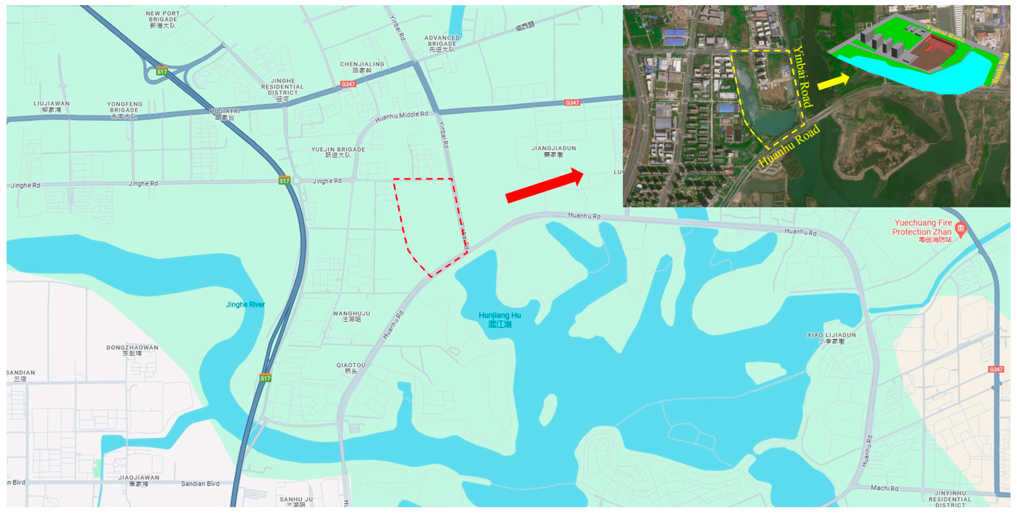
4.1. Project Overview

The China Construction YipinLanhui Phase I project is located north of Huanhu Road and west of Baiyin Road, Jinyinhu Street, Dongxihu District, Wuhan City, with a total land area of 18,763.13 square meters. The actual geographical map is shown in Figure 6.
Obtain a virtual scene model through BIM parametric modeling, including geological layers, pile foundations, and site models. In its form after being lightweight on the web page, it is shown in Figure 7.
The project pile foundation work is divided into two work areas with a total of 288 bored piles, with 199 for the office building area (Zone A) and 89 for the Office Support Facility Area (Zone B), respectively. The initial zoning status is shown in Figure 8.

4.2. Application Analysis

Based on the initial zoning, we planned to adjust the zoning of Zone A, dividing the currently completed pile foundation (dark pile foundation in Figure 9) into Zone C. To fully reflect the role of the zoning system in the dynamic adjustment process of the construction area, one of the completed piles in Zone A, pile No. G-251, and one unworked pile, No. G-206, were selected as observation objects for analysis. The pile foundation attribute parameters before partition adjustment are shown in Table 5.
Re-edit the boundaries of the original “Work Area A”, use the virtual work area delineation and interaction method, and add a new work area. The boundary area was named “Work Area C”, as shown in Figure 10.
After adjustment, the attribute parameters of pile foundations G-251 and G-206 were checked again. The “zoning name” of the original G-251 pile foundation in Zone A was updated to “Zone C”, while the attributes of pile foundation G-206 remained unchanged, as shown in Table 6. The changes in the attribute parameters of both piles were in line with expectations.
Different ways of dividing the work zones and parameters were derived for different working conditions, as shown in Figure 11, Figure 12 and Figure 13, respectively.
The dynamic automatic zoning method based on BIM technology for group pile multi-work zone construction was successfully applied to Phase I of the Zhongjian project. This method adjusted the original zone division of Zone A, reassigned completed piles to Zone C, and redefined boundaries using a virtual work zone division and interaction method. It also adjusted the parameters of the piles within the zoning system, ensuring that the changes in the attribute parameters of the pile numbers met expectations. Compared to traditional methods, this approach was faster and more efficient, allowing for quick adjustments in construction zoning and optimizing the digital information system for construction management.

5. Conclusions

The construction management mode of pile foundations is a key factor affecting construction progress and project settlement. While the division of labor brings efficiency improvement, it also puts higher requirements on pile foundation management. It not only requires accurate correspondence between the work area and pile number data, but more importantly, it is necessary to maintain this correspondence in the dynamic changes in the work area. Some conclusions could be drawn as follows:
(i)
This study develops a dynamic zoning and adjustment method for pile foundation construction areas based on the BIM model. This approach supports the creation of an information management system, enhancing the management of construction teams, improving construction efficiency, and meeting the demands for the dynamic adjustment of construction area zoning.
(ii)
A set of adaptive zoning methods based on the dynamic adjustment of construction work areas was proposed. This method achieved the division and interaction of virtual work zones by calculating the spatial relationship between the pile foundation model and the work zone area model. By using a database to associate the model with construction data, the method ultimately allowed for the adaptive adjustment of pile foundation zoning parameters.
(iii)
The parameterized construction method based on the group pile BIM model and the adaptive zoning construction management method proposed in this study were applied to the construction site and work area division of the China Construction Yipin Lanhui Phase I project. The modeling effect of the pile foundation conformed to the engineering design distribution, and the division of work areas accurately reflected the on-site construction status. All functions met the desired goal of addressing the challenges of adaptive zoning in pile construction, improving the digital management level of pile foundation construction, and enhancing the construction of digital twin systems for pile foundation projects.
(iv)
In the future, more intelligent algorithms could be employed to realize real-time monitoring and feedback through the combination of on-site sensor technology. The application of augmented reality (AR) and virtual reality (VR) technologies could further enhance construction efficiency. Additionally, integrating artificial intelligence (AI) and big data analysis could enable more accurate construction management.

Author Contributions

Conceptualization, L.N.; Methodology, W.Z.; Software, J.C.; Validation, H.J.; Formal analysis, M.F.; Investigation, W.Z.; Writing—original draft, Y.Z.; Writing—review & editing, M.F.; Visualization, H.J.; Supervision, L.N.; Project administration, W.Z., J.C. and W.Y. All authors have read and agreed to the published version of the manuscript.

Funding

This study was jointly financially supported by the Shijiazhuang Innovative Application Scenario Project (Grant No. 241230064A), the Central Government Guide Local Science and Technology Development Fund Project of Hebei Province (Grant No. 236Z0804G), and the National Key Research and Development Program of China (Grant No. 2022YFC3802200).

Data Availability Statement

Data are contained within the article.

Conflicts of Interest

Authors Wei Zhou, Jiaxi Chen and Weijun You were employed by the company China Construction Third Bureau First Engineering Co., Ltd. The remaining authors declare that the research was conducted in the absence of any commercial or financial relationships that could be construed as a potential conflict of interest.

References

  1. Yu, H.; Wen, B.; Zahidi, I.; Fai, C.M.; Madsen, D. Constructing the future: Policy-driven digital fabrication in China’s urban development. Results Eng. 2024, 22, 102096. [Google Scholar] [CrossRef]
  2. Shao, S.; Cao, D. Contagion of BIM implementation practices in interproject networks: An empirical study in China. J. Manag. Eng. 2024, 40, 05023009. [Google Scholar] [CrossRef]
  3. Yang, Y.; Shao, S.; Cao, D. Diffusion of BIM policies in China: An event history analysis. Eng. Constr. Archit. Manag. 2024. [Google Scholar] [CrossRef]
  4. Song, S.Y.; Lin, J.R.; Zhou, Y.C.; Ding, W.Q. Parameterized FEA Model Generation and Simulation of Underground Structures Based on BIM: A Case Study. Comput. Civ. Eng. 2021, 2021, 408–416. [Google Scholar] [CrossRef]
  5. Qiao, J.; Guan, T.; Zhu, J. Exploration of BIM model creation method for highway engineering based on Revit+Dynamo software. In Proceedings of the Tenth International Conference on BIM Technology—BIM Enabling High-Quality Development of the Construction Industry, Hong Kong, China, 30–31 May 2024; pp. 273–277. [Google Scholar]
  6. Filardo, M.M.; Akula, R.; Walther, T.; Bargstädt, H.J. Automated Framework for Optimized Path-Planning for Pile Foundation Drilling Machines Based on 4D BIM Modelling. In Proceedings of the IABSE Congress Ghent 2021 —Structural Engineering for Future Societal Needs, Ghent, Belgium, 22–24 September 2021. [Google Scholar] [CrossRef]
  7. Wang, Y.; Wang, Y.; Yang, Z.; Wang, Q.; Zhang, H. A hybrid building information modeling and collaboration platform for automation system in smart construction. Alex. Eng. J. 2024, 88, 80–90. [Google Scholar] [CrossRef]
  8. Hosny, A.; Nik-Bakht, M.; Moselhi, O. Physical distancing analytics for construction planning using 4D BIM. J. Comput. Civ. Eng. 2022, 36, 04022012. [Google Scholar] [CrossRef]
  9. Singh, V.V.; Tommelein, I.D. Visual Workload Leveling and Zoning Using Work Density Method for Construction Process Planning. J. Constr. Eng. Manag. 2023, 149, 04023102. [Google Scholar] [CrossRef]
  10. Wei, W.; Lu, Y.; Lin, Y.; Bai, R.; Zhang, Y.; Wang, H.; Li, P. Augmenting progress monitoring in soil-foundation construction utilizing SOLOv2-based instance segmentation and visual BIM representation. Autom. Constr. 2023, 155, 105048. [Google Scholar] [CrossRef]
  11. Xie, H. Four-dimensional visualized dynamic construction simulation application based on BIM technology. J. Shandong Agric. Univ. (Nat. Sci.) 2018, 49, 825–827. [Google Scholar]
  12. Alsanabani, N.M.; Al-Gahtani, K.S.; Almohsen, A.S.; Alsharef, A. Risk Interdependency Network Model for the Cost and Time of Pile Installation in Saudi Arabia, Using Partial Least Squares Structural Equation Modeling. Appl. Sci. 2023, 13, 10886. [Google Scholar] [CrossRef]
  13. Hou, X.; Li, C.; Fang, Q. Computer vision-based safety risk computing and visualization on construction sites. Autom. Constr. 2023, 156, 105129. [Google Scholar] [CrossRef]
  14. Wu, D.Y.; Qu, B.B.; Zhao, J.H. The application of intelligent control in the entire process of drilling and grouting pile construction. Water Transp. Eng.
  15. Jiang, Y.Y.; Wu, R.; Zhao, S.Z. Application of intelligent monitoring system for cast-in-place pile construction based on combination positioning technology. Build. Struct. 2023, 53, 2038–2042. [Google Scholar] [CrossRef]
  16. Zhang, Z.W.; Cao, W.F.; Yuan, L.S. A Progress Management Method for Pile Foundation Construction Based on BIM+Smart Construction Platform. Urban Rail Transit Res. 2022, 25, 180–185. [Google Scholar]
  17. Yang, Q.; Yan, X.; Chen, W. Construction and Application of Safety Management Scenarios at Construction Sites. Appl. Sci. 2024, 14, 404. [Google Scholar] [CrossRef]
  18. Gotman, A.L. Pile Foundations as an Efficiently Developing Direction of Foundation Engineering. Soil Mech. Found. Eng. 2020, 57, 179–190. [Google Scholar] [CrossRef]
  19. Tiwari, A.; Dindorkar, N.; Kaur, S. Bibliometric and Knowledge Network of Global Research on Pile Foundations: A Review of Recent Developments. Sustainability 2023, 15, 11108. [Google Scholar] [CrossRef]
Figure 1. The objective of BIM-based zoning on group piles.
Buildings 14 02071 g001
Figure 2. A schematic of the scene model.
Buildings 14 02071 g002
Figure 3. Dynamic zoning processing: (a) initial zone; (b) adjusted zone.
Buildings 14 02071 g003aBuildings 14 02071 g003b
Figure 4. The seven-parameter transformation process.
Buildings 14 02071 g004
Figure 5. The method flowchart.
Buildings 14 02071 g005
Figure 6. The actual geographical location.
Buildings 14 02071 g006
Figure 7. Virtual scene BIM model.
Buildings 14 02071 g007
Figure 8. Initial work zone distribution and parameters.
Buildings 14 02071 g008
Figure 9. A schematic of the distribution of observation objects.
Buildings 14 02071 g009
Figure 10. Adjusted work zone distribution and parameters.
Buildings 14 02071 g010
Figure 11. Work zone distribution and parameters for the first operating condition.
Buildings 14 02071 g011
Figure 12. Work zone distribution and parameters for the second operating condition.
Buildings 14 02071 g012
Figure 13. Work zone distribution and parameters for the third operating condition.
Buildings 14 02071 g013
Table 1. The structure of the model hierarchy.
LevelPile Foundation ModelGeological ModelConstruction Scene Model
family categorystructural foundationmatrixarea
family typeengineering pilesStratigraphic name 1Terrestrial environment
Family subtypegrouted pileStratigraphic name 1Terrestrial environment
an actual exampleExamples of engineering pilesExample of stratum name 1Examples of ground environments
Table 2. Table of piling attribute parameters.
Property FieldsAttribute DescriptionUnit (of Measure)
SubdivisionMain zoning parameters, automatically adjusted to changes in the work area/
Pile E CoordinateOne of the engineering coordinates of the pile foundation pointsMeters (m)
Pile N coordinatesOne of the engineering coordinates of the pile foundation pointsMeters (m)
stakeUnique numbering of staking points/
Table 3. The data structure of tb_project_pile_part.
Field NameField TypeAllow Null ValuesChinese Interpretation
IDBIGINT(19)NOprimary key
project_idBIGINT(19)NOProject ID
model_file_idBIGINT(19)NOModel File ID
part_nameVARCHAR(100)YESPartition name
part_areaVARCHAR(100)YESSub-area (square meters)
part_boundaryVARCHAR(1000)YESPartition boundaries
part_heightVARCHAR(100)YESPartition height
part_componentsTEXTYESList of pile components in the zoning district
Table 4. The data structure of tb_pile_info.
Field NameField TypeAllow Null ValuesChinese Interpretation
IDBIGINT(19)NOprimary key
project_idBIGINT(19)NOProject ID
model_file_idBIGINT(19)NOModel File ID
pile_typeVARCHAR(255)YESPile type
pile_part_idBIGINT(19)YESSubdivision
pile_xVARCHAR(255)YESPile X coordinate
pile_yVARCHAR(255)YESPile Y coordinate
pile_noVARCHAR(255)YESstake
Table 5. Pile foundation attribute parameters before zoning adjustment.
Zoning NamePile NumberPile Foundation StatusDesigned Pile Position Coordinates
Zone AG-251Completed394,701.09025, 784,656.886603
Zone AG-206Not under construction394,699.37928, 784,648.025236
Table 6. Adjusted pile foundation attribute parameters.
Zoning NamePile NumberPile Foundation StatusDesigned Pile Position Coordinates
Zone CG-251Completed394,701.09025, 784,656.886603
Zone AG-206Not under construction394,699.37928, 784,648.025236
Disclaimer/Publisher’s Note: The statements, opinions and data contained in all publications are solely those of the individual author(s) and contributor(s) and not of MDPI and/or the editor(s). MDPI and/or the editor(s) disclaim responsibility for any injury to people or property resulting from any ideas, methods, instructions or products referred to in the content.

