Article

Investigation of the Temperature Distribution and Energy Consumption of an Integrated Carbon Fiber Paper-Embedded Electric-Heated Floor

1
China National Bamboo Research Center, Hangzhou 310012, China
2
Key Laboratory of High Efficient Processing of Bamboo of Zhejiang Province, Hangzhou 310012, China
3
College of Mathematics and Computer Science, Zhejiang A&F University, Hangzhou 311300, China
4
Harbin Institute of Forestry Machinery, State Forestry and Grassland Bureau, Harbin 150086, China
*
Authors to whom correspondence should be addressed.
Buildings 2024, 14(7), 2097; https://doi.org/10.3390/buildings14072097
Submission received: 24 May 2024 / Revised: 3 July 2024 / Accepted: 4 July 2024 / Published: 9 July 2024
(This article belongs to the Special Issue Advanced Building Technologies for Energy Savings and Decarbonization)

Abstract

:
This study examined spatial and temporal thermal performance and energy consumption. The temperature distribution in the running period was monitored in test rooms with integrated electric- and hot water-heated floors. The short- and long-term energy consumption of the two heating systems were recorded and compared. The results indicated that the integrated electric heating system generated higher temperatures for indoor air and on the exterior surface of the wooden floor than the hot water heating system; meanwhile, the difference in the mean temperatures of the exterior and rear surfaces of the electric-heated floor was 2.44 °C, while that of the hot water-heated test room was 13.25 °C. The efficient structure of the integrated electric heating system saved 22.97% energy compared to the hot water system after short-term (7 h) charging and reaching a dynamic balance, and it efficiently increased the energy utilization rate to 11.81%. After long-term charging, the daily energy consumption of the integrated electric heating system consumed much less energy than the hot water system every month. The integrated electric heating system saved 62.55% and 34.30% of energy in May and January, respectively, and consumed less than half of the energy the hot water system consumed in the less cold months. Therefore, a high-efficiency and energy-saving integrated electric-heated floor could be a potential indoor heating solution.

1. Introduction

Indoor thermal environments are increasingly popular as they involve human health [1], comfort [2,3], environmental pollution [4], and energy consumption [5]. Given the current increasingly strong awareness of energy conservation, energy conservation research of indoor heating has been vitally important in developing energy consumption [5].
Bojić et al. compared the performance of different radiant heating systems on walls, ceilings, and floors and reported that floor heating involved the lowest energy and operation costs [6], which was consistent with Fabrizio’s study [3]. Using energy substitution technology, Zhang et al. proposed that the radiant floor heating system is highly efficient and environmentally protective [7]. The earliest radiant floor heating systems used hot gases and were termed “kang” and “dikang”, which were used in China in the 11th century BC [8]. The modern fluid-based systems began with the circulating hot water patent from Europe in 1839. Since then, the circulating hot water-based radiant floor heating system has improved and developed into a widely used indoor heating system in residential buildings [9,10]. Rohdin et al. investigated energy-conservation strategies for improving the hot water floor heating system, such as a proportional flux modulation strategy and a two-parameter on–off control strategy [11]. Cho explored a predictive control strategy involving the intermittently heated radiant floor heating system and reported that 10–12% of energy could be saved [12]. However, the disadvantages of hot water floor heating systems were as apparent as the advantages. Hu et al. [13] summarized the practical application of the radiant floor heating system in mainland China, where the long response time of the hot water floor heating systems was a drawback. A compared simulation analysis of low-temperature hot water floor radiant heating and electrical floor radiant heating by Qi et al. [14] indicated a more uniform floor surface temperature distribution of electrical radiant floor heating. While the hot water system warming is time-consuming and the temperature is inhomogeneous, the system is still widely used in many residential buildings. Thus, the hot water heating system must be used as a reference in electrical radiant floor heating system analysis.
Various forms of electrical radiant floor heating systems have been developed. In the mid-20th century, radiant heating using concrete-embedded copper pipes was extensively applied in the first large-scale multi-building project in New York, the United States [9]. After that, energy-saving and thermal performance improvement strategies were researched. The 1970s marked the early phase of radiant floor heating system research and application. For example, steel wire fabric was used to form an electrical loop in concrete floors for storing heat [15]. The structure of the cable-embedding matrix material might influence temperature transformation and distribution [16,17]. Yan et al. [18] compared the thermal performance of cable radiant heating floors in three different structures and reported that the ready-made thin structure had relatively good thermal and mechanical properties. Similarly, heating system structures significantly affect thermal performance [19]. Furthermore, the aforementioned report involved energy saving and reported that electrically heated floors shifted 84% of the building load to nighttime, which saved costs based on off-peak electricity prices [19].
Based on the above literature review, embedded structures generally conduct much more heat loss to the ground and consume more energy, while the heating unit of wire-like materials causes temperature inhomogeneity on the floor surface. Fontana [20] placed a thick aluminum sheet above the electrical heater to reduce the surface temperature non-uniformity. However, this action might complicate the structures, which is not conducive to manufacturing. A heating unit that uses advanced materials converts wire-like materials (cables) to facet materials (carbon crystal membrane, carbon black mortar slabs, and carbon fiber paper (CFP)). Carbon fiber is an advanced high-strength material with an efficient electro-thermal conversion efficiency approach nearing 100% [21,22], from which integrated electric floor heating was developed. Carbon fiber is blended with plant fiber [23] to produce CFP [24,25], which is generally used in high-performance capacitors [26] and fuel cells as electrodes [27,28]. CFP has substantial potential for indoor thermal application due to its prominent advantages of electro-thermal conversion efficiency > 97% [29] and emission of health-beneficial infrared rays of 8~15 μm [30].
Electric-heated floors consist of three layers [30,31]: a wooden facial layer [32], a heating unit [33], and a wooden matrix layer, and they are connected to the energy source using two electrodes at both ends of the floorboards [31]. Compared with the wire-like heating unit (electric cables and water pipes), CFP has a much greater heating area and uniform temperature distribution as a facet heating unit. While the properties of wooden electric heating composites were comparatively well investigated, investigations of the performance of electric floor heating as compared with the conventional heating system remain indispensable to researchers and consumers.
The literature review indicates that the radiant floor heating system is a highly efficient and energy-saving indoor heating system. Furthermore, the application of advanced materials is an inevitable trend due to their high performance and as a solution to surface temperature non-uniformity. However, previous works mainly focused on theoretical and trial sample experimental studies of wooden electric heating composites, which cannot represent its performance as a radiant heating system in practical projects, including its energy-saving and thermal performance attributes.
This study developed an electric heating system with the CFP integrated in a wooden floor which could be used directly on electricity, and two identical experimental rooms were used for short- and long-term energization experiments with the electric heating system and the hot water heating system. A comparative study was conducted to investigate the temperature distribution, energy consumption and energy utilization of the two heating systems and aimed to visually demonstrate the indoor temperature and energy efficiency of the designed electric heating system. The authors intended to propose a high-efficiency and energy-saving radiant floor heating system.

2. Materials and Methods

2.1. Materials

Figure 1a demonstrates that the integrated electric-heated floor consisted of a wooden floor, heating unit, power cables, and a temperature controller. The CFP was obtained in accordance with the methodology outlined in reference [34], and its volume resistivity was found to range 10−1~104 Ω·cm. The front board was constructed from red oak, while the matrix board was made from eucalyptus composite board.

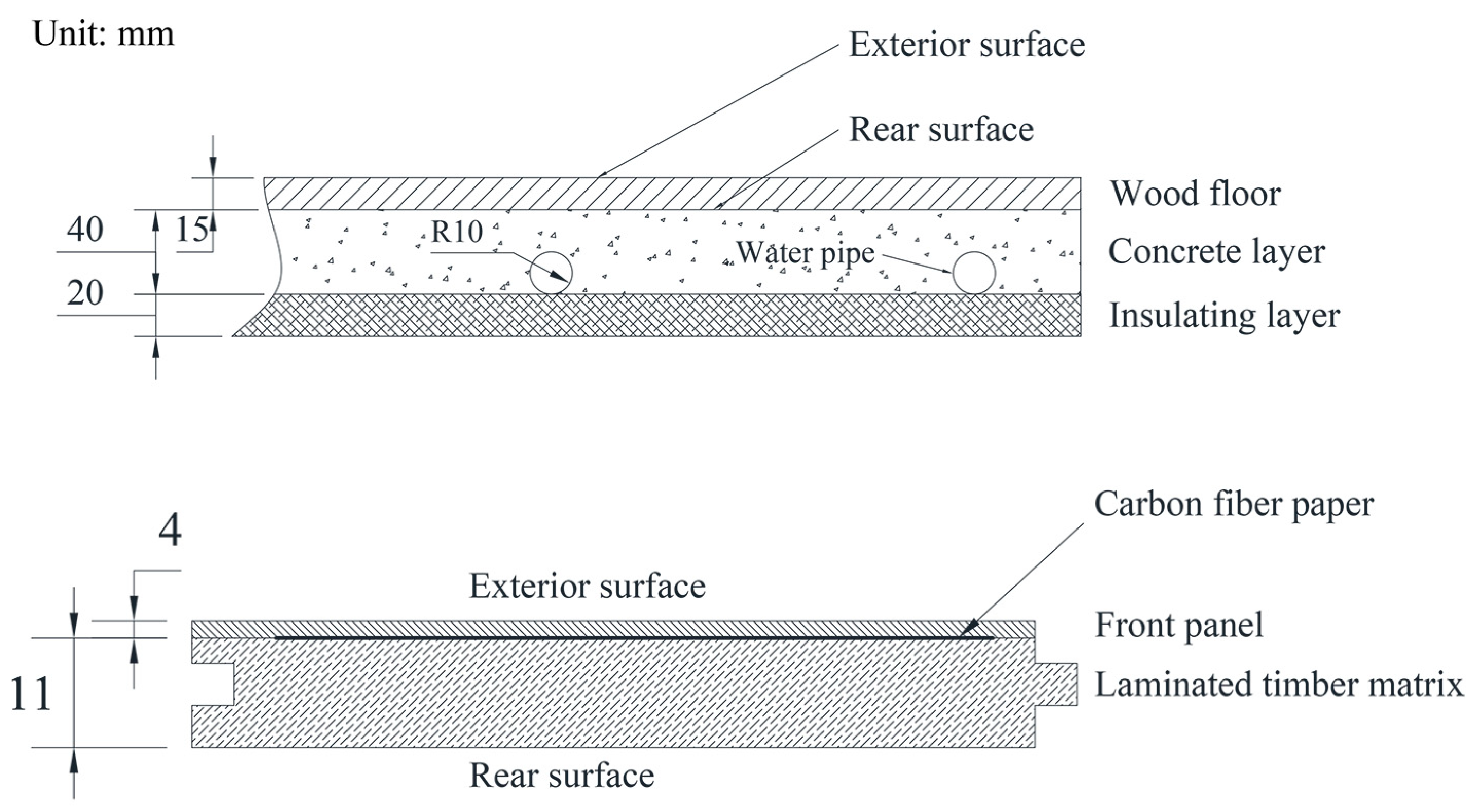
2.2. Methods of Preparing Integrated Electric Floor and Test Room

As shown in Figure 2, the heating unit (CFP with two electrodes pasted on two sides) was embedded in wood veneers with glue between the front board and matrix board. The hot water floor heating system involved water pipes embedded in a cement matrix, placed on concrete, and covered by a wood floor. A temperature regulatory controlled the temperature approaches of the two systems. In this study, both systems used electricity as the energy source. The wooden floor in the integrated electric heating system was directly connected to the electricity power supply. In the hot water heating system, water was heated by an electric boiler with 98% conversion efficiency, flowed cyclically, and was turned into the indoor heat source.
The two systems were tested in two adjacent empty rooms in an experimental base of China National Bamboo Research Center, which was the new laboratory building, located at Jieruo Village, Huzhou City, Zhejiang Province. Figure 1b displays that the test rooms covered approximately 22 m2 and were 3.70 m high indoors. The walls of the rooms are constructed of 240 mm brick walls covered with layers of cement, putty, and paint. The original floor is composed of poured cement. Each test room contained a south-facing window (2400 mm wide × 2800 mm high) opposite a north-facing door.
Figure 2 presents that the integrated electric-heated floor was laid on floor joists as a standard floor. However, the floor joists in the integrated electric-heated floor were filled with thermal insulation materials and covered with a reflective film. The electric cables were linked to the back of the floor with a pair of fasteners. A series connection was used for the power supply between floorboards. The hot water floor heating system consisted of a wooden floor layer, cement matrix layer, and insulating layer, which were laid on the concrete layer of the structure. The cement matrix layer was 40 mm high and laid on the 20 mm thick insulating layer. The electric boiler was set up on the veranda with no exposed pipes.

2.3. Methods of Temperature Distribution Test

Based on human foot and chest comfort zones [35], the temperature test experiment was conducted by establishing eight test points at eight evenly distributed locations within the test room. The aforementioned points were positioned vertically at the rear surface of the floorboard, on the exterior surface of the floorboard, and at 100 mm and 1100 mm above the floorboard, respectively. The temperature data were collected in real time by a 64-channel portable temperature tracker mentioned in the reference [32], which has an accuracy of 0.1 °C. The power was shut off when the temperature reached equilibrium.

2.4. Methods of Energy Consumption Computation

Both heating systems used electricity as the energy source, which was convenient for comparative analysis of energy consumption. Water in the hot water system was heated using an electric boiler, and the integrated electric system used CFP as the electro-thermal conversion unit. During the experiment, the doors, windows and other channels connected to the outside of the two experimental rooms were all closed and sealed in order to exclude the interference of external factors and to ensure that the data collected by fixed temperature sensors was as accurate as possible. In order to carry out the relevant calculations, the airflow in the experimental rooms was set to be purely natural convection. Based on the law of energy balance, the heat balance of the system was calculated using the following equation:
Φ T = Φ a + Φ l
where ΦT is the heat supply by CFP under charging or water, Φa is the heating capacity for heating the air in the test room, and Φl is the heat loss from the entire heating system. The heat supply by CFP under charging or hot water, Φ, was calculated as follows:
Φ T = W T η
where W is the electric power, T is the charging duration, and η is the heat efficiency. The heating capacity for heating the air in the test room, Φa, was calculated as follows:
Φ a = h t o t A t s t a
where A is the floor surface area, ts and ta are the wooden floor surface and room air temperatures, respectively, and htot is the total heat transfer rate of the wooden floor surface, which consisted of the convective heat transfer coefficient hc and radiant heat transfer coefficient hr. The h c was calculated as follows according to recommendations in the literature [36]:
N u = 0.15 G r P r 1 / 4 ,   10 7 G r P r 10 11
G r = g α V t l 3 v 2
P r = v a
h c = N u λ l
where N u , G r , and P r are the Nusselt, Grashor, and Prandtl numbers, respectively. α V , v , a , and λ are the coefficient of cubical expansion, kinematic viscosity, thermal diffusivity, and thermal conductivity of air, respectively. l is the characteristic length calculated by A/P (surface area divided by perimeter) [36,37]. The values of each parameter in the aforementioned equation, as calculated in this paper, are presented in Table 1, which was sourced from reference [36]. The hr was calculated as follows as described previously [36]:
h r = ε σ T s 2 + T a 2 T s + T a
where ε is the floor surface emissivity with the value of 0.81 [36], and σ is the Stefan–Boltzmann constant with the value of 5.67 E−8 W m−2 K−4 [37]. The energy utilization rate was defined as the percentage of the heating capacity for heating air in the heat supply and was calculated as follows:
c = Φ a Φ T × 100 %

3. Results

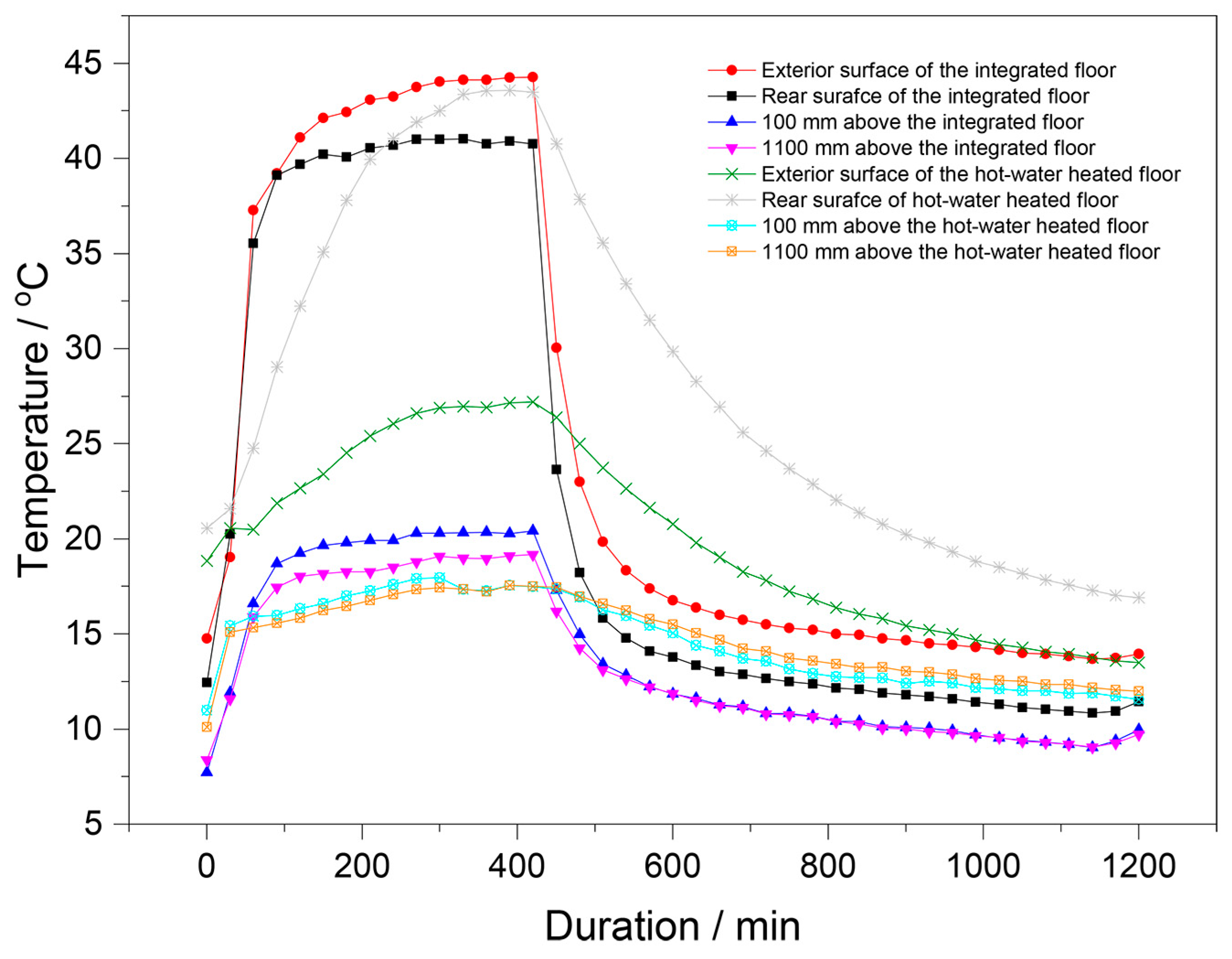
3.1. Temperature Distribution

The vertical temperature curves of the two test rooms according to time and height over 20 h are depicted in Figure 3 and were measured at 8:00 a.m. to 12:00 p.m. the following day. Both the floor’s exterior surface and rear surface reached their set temperature at the fastest rate and maintained equilibrium. Nevertheless, the vertical temperature of the integrated electric heated floor exhibited a rapid increase to its maximum value, after which it remained stationary.
The vertical temperatures in both rooms were stratified. Both heating systems employed a process whereby heat radiated from the floor to the air, thus providing a means of heating. Table 2 presents the temperature distribution in the vertical direction. The average temperature of the exterior surface of the electric heating system was 42.55 °C, which was higher than the average temperature of the rear surface, which was 40.11 °C. This is in contrast to the hot water heating system, where the exterior surface temperature was lower than the rear surface temperature. In terms of vertical distribution, the indoor air temperature was observed to be higher at a height of 100 mm above the floor surface than at 1100 mm above the floor surface for both systems. However, at the same height, the electric heating system was observed to be hotter than the water heating system. The average temperature under dynamic balance status was 18.37 °C at the 1100 mm measurement point in the electric-heated room, which reached 18 °C indoor air temperature and led to the lowest energy consumption rate according to Koca et al. [38], while of the hot water-heated room was 16.75 °C. The electric-heated room felt warmer under the feet as the temperature was 40–45 °C on the wooden floor exterior surface.
Both heating systems radiated heat from the floor to the air for the purposes of heating. However, the average temperature of the surface plate in an electric heating system is 42.55 °C, which is higher than the temperature of the back plate, which is 40.11 °C. This is in contrast to the water heating system, where the temperature of the surface plate is lower than that of the back plate. The indoor air temperature of both systems is found to be higher at a depth of 100 mm than at a depth of 1100 mm. However, it is observed that the temperature is higher at the same depth in the electric underfloor heating system.
Figure 4 depicts that the exterior and rear surface temperatures were measured in the coldest winter months. In the integrated electric heating systems, the temperature of the exterior surface was found to be higher than that of the rear surface, whereas in the hot water heating system, the temperature of the exterior surface was lower than that of the rear surface. The temperature discrepancy of the exterior and rear surfaces of the electric-heated floor was significantly small. The difference in the mean temperatures of the exterior and rear surfaces of the electric-heated floor was 2.44 °C, while that of the hot water-heated test room was 13.25 °C.

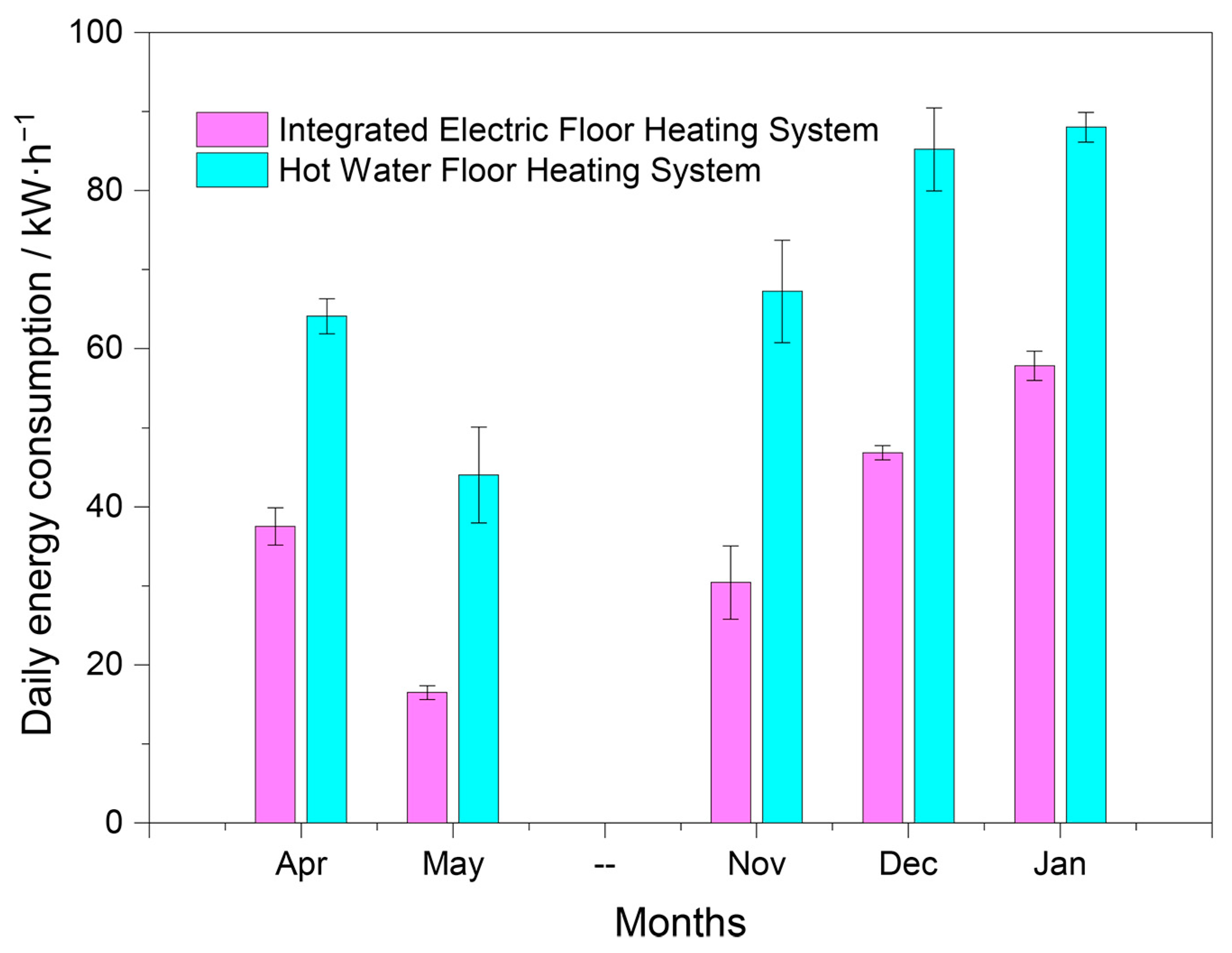
3.2. Energy Consumption

The energy consumption of the two heating systems for 7 h was calculated after reaching dynamic balance. Figure 5 presents that the energy consumption value (Φ) of the integrated electric-heated floor and the hot water-heated floor test rooms were 31.70 and 41.16 kW h−1, respectively. The integrated electric heating system used 22.97% less energy than the hot water heating system.
The thermal mass transferred from the wooden floor exterior surface to the indoor air in the two systems presented different energy utilization rates (c) based on the calculations of Equation (9). The energy utilization rate of the hot water system was 2.79%, while it was 9.02% higher in the integrated electric system (11.81%).
The average daily power consumption of the two heating systems per month was computed after long-term operation in the warm spring months and cold winter months (Figure 6). The systems consumed much more energy when the weather became colder. Specifically, the integrated electric system consumed less than half of the energy the hot water system consumed in the less cold months of May and November. The integrated electric heating system saved 62.55% and 34.30% of energy in May and January, respectively.

4. Discussion

4.1. Temperature Distribution

Radiant floor heating may be conceptualized as a process of natural convection in a large space with a horizontal thermal surface oriented upwards. Convective and radiative heat transfer occurred from the heated wooden floor to the air, resulting in the gradual heating of the air above the wooden floor from near to far as the feature length. Therefore, the air temperature disparity of the test rooms was caused by the disparate wooden floor exterior surface temperatures. Nevertheless, the transfer of heat between the wooden floor and the heating unit occurred via thermal conduction. The location of the heat-generating unit has a significant impact on the efficiency of heat transfer and utilization. Meanwhile, wood has a low thermal conductivity; for example, pine has a thermal conductivity of 0.15 W m−2 K−4 [35], which makes heat transfer inefficient. Therefore, it is necessary to reduce the obstruction of the heat conduction process by the wooden floor in order to improve the heat transfer efficiency.
Figure 2 and Figure 4 manifest that the wooden floor exterior surface of the integrated electric heating system benefitted from the effective structure as its temperature was much higher than the rear surface, which was opposite to the hot water-heated floor. The CFP is the heating unit of electric-heated floors [31,33] and has an efficient conversion of ~97% [29]. The CFP was placed between the front panel and wood laminated timber matrix [32] (Figure 2), resulting in a 4 mm distance to the exterior surface and efficient heat transfer. Furthermore, CFP instantly heats while charging [31,33], resulting in more energy transfer to the indoor air. Figure 4 indicates that the temperature of the exterior surface of the electric-heated floor reached 40 °C in 30~60 min. Contrastingly, the hot water heating floor system required ~4 h to reach dynamic balance.
The disparity in temperature of the exterior surface and rear surface between the integrated electric heating floor and the hot water heating floor could be attributed to the distinct structural characteristics of each. As illustrated in Figure 2, the heating unit of the integrated electric heating floor was embedded directly in the floor, a mere 4 mm below the floor surface. During the charging process, heat was transferred directly from the heating unit (CFP) to the floor surface. Due to the low thermal conductivity of wood and the aforementioned fact that the thickness from CFP to the rear surface was much less than that to the exterior surface, the exterior surface temperature of the floor was higher than that of the rear surface of the floor in the integrated electric heating floor system. In contrast, the heat unit of the hot water heating floor system was situated beneath the floor, as illustrated in Figure 2. The transfer of heat from the hot water occurs via the concrete layer to the rear surface of the wooden floor, subsequently reaching the exterior surface of the wooden floor, which resulted in a higher temperature at the rear surface than at the exterior surface of the wooded floor.

4.2. Energy Consumption

The utilization of high-efficiency heating units is a significant contributing factor to the energy efficiency of radiant floor heating. According to the literature [21,22], the efficient electro-thermal conversion efficiency of carbon fiber approached nearing 100%, and CFP, which is manufactured from carbon fiber, exhibits an electro-thermal conversion efficiency of greater than 97% [29]. The rationale behind the utilization of CFP as a heat-generating unit in this study is to enhance the efficiency of electro-thermal conversion. The use of CFP allowed the integrated electric heating floor system to function as an instantaneous electric radiation heating floor system, thereby demonstrating the effect of energy saving, which was consistent with Cho’s research [12].
Conversely, the reliability of structural design is a contributing factor to the enhancement of energy efficiency in radiant floor heating. The integrated electric heating floor system saved energy and achieved higher energy efficiency than the hot water heating floor system, which was primarily due to structural improvements, as the heating units were relocated to a higher position. In contrast to the heating unit of the hot water heating floor system embedded in the concrete matrix layer, the closer the heating unit of the integrated electric heating floor system was to the surface, the lower the heat lost to the underground, thus allowing for a greater transfer of heat to the indoor air, which is essential for the purpose of heating. Consequently, the enhancement of the electric heating floor system structure in this study represents an efficacious energy-saving strategy and indoor heating solution.

5. Conclusions

In terms of vertical distribution, the average temperature of the indoor air decreased with increasing height in both radiant heating systems. However, the average temperature of the exterior surface of the electric heating system was higher than that of the rear surface, which was in contrast to the hot water heating system. The smaller temperature discrepancy between the exterior and rear surfaces led to the high rate of temperature rise of the integrated electric floor heating system, which addressed the shortcomings of the long reaction time of the water heating system proposed in reference [13].
The integrated electric floor heating system saved 22.97% energy compared to the hot water heating system for 7 h charging after reaching dynamic balance and efficiently increased the energy utilization rate to 11.81%. The long-term charging demonstrated that the integrated electric heating consumed much less energy daily than hot water heating every month. Furthermore, the integrated electric heating system consumed less than half of the energy consumed by the hot water system in the less cold months. This corroborates the efficacy of radiant floor heating systems, as described in the literature, as a highly efficient and energy-saving indoor heating system.
The results indicated that integrated electric floor heating was a more efficient and energy-saving radiant floor heating system for indoor heating. Generally, the integrated electric floor heating system is a potential solution for efficient and energy-saving indoor heating.

Author Contributions

Conceptualization, Y.S. and C.H.; methodology, C.H. and X.W.; validation, Y.B. and G.Y.; formal analysis, Y.B. and N.L.; resources, S.H.; data curation, Y.B. and C.H.; writing—original draft preparation, C.H. and Y.B.; writing—review and editing, X.W., Y.B. and C.H.; visualization, X.W. and N.L.; supervision, S.H. and G.Y.; project administration, Y.S.; funding acquisition, C.H. All authors have read and agreed to the published version of the manuscript.

Funding

This study was supported by the Fundamental Research Funds for the Central Non-profit Research Institution of Chinese Academy of Forestry, CAFYBB2020MB009, CAFYBB2016ZD008.

Data Availability Statement

The data presented in this study are available on request from the corresponding authors.

Conflicts of Interest

The authors declare no conflicts of interest.

Nomenclature

AArea, m2
cEnergy utilization rate
GrGrashor number
htotTotal heat transfer rate, W m−2 K−1
hcConvective heat transfer coefficient, Wm−2 K−1
hrRadiant heat transfer coefficient, W m−2 K−1
NuNusselt number
PrPrandtl number
TTime, h
tTemperature, °C
WElectric power, kW h−1
Greek symbols
ΦEnergy, W
ηHeat efficiency
εFloor surface emissivity
σStefan–Boltzmann constant, W m−2 K−4
υKinematic viscosity of air, m2 s−1
αVCoefficient of cubical expansion of air, m2 s−1
αThermal diffusivity of air, m2 s−1
λThermal conductivity of air, W m−1 K−1
ιCharacteristic length
Subscripts
sWooden floor surface
aIndoor air
lHeat loss

References

  1. Ji, P.; Rhoads, W.J.; Edwards, M.A.; Pruden, A. Impact of water heater temperature setting and water use frequency on the building plumbing microbiome. ISME J. 2017, 11, 1318–1330. [Google Scholar] [CrossRef] [PubMed]
  2. Chen, Q. Comfort and energy consumption analysis in buildings with radiant panels. Energy Build. 1990, 14, 287–297. [Google Scholar] [CrossRef]
  3. Fabrizio, E.; Corgnati, S.P.; Causone, F.; Filippi, M.D. Numerical comparison between energy and comfort performances of radiant heating and cooling systems versus air systems. HVAC&R Res. 2012, 18, 692–708. [Google Scholar]
  4. Leivo, V.; Prasauskas, T.; Du, L.; Turunen, M.; Kiviste, M.; Aaltonen, A.; Martuzevicius, D.; Haverinen-Shaughnessy, U. Indoor thermal environment, air exchange rates, and carbon dioxide concentrations before and after energy retro fits in Finnish and Lithuanian multi-family buildings. Sci. Total Environ. 2018, 621, 398–406. [Google Scholar] [CrossRef] [PubMed]
  5. MacNaughton, P.; Cao, X.; Buonocore, J.; Cedeno-Laurent, J.; Spengler, J.; Bernstein, A.; Allen, J. Energy savings, emission reductions, and health co-benefits of the green building movement. J. Expo. Sci. Environ. Epidemiol. 2018, 28, 307–318. [Google Scholar] [CrossRef]
  6. Bojić, M.; Cvetković, D.; Marjanović, V.; Blagojević, M.; Djordjević, Z. Performances of low temperature radiant heating systems. Energy Build. 2013, 61, 233–238. [Google Scholar] [CrossRef]
  7. Zhang, L.; Cao, B. Design and analysis of a floor radiant heating system based on energy substitution technology. Appl. Sci. 2018, 8, 491. [Google Scholar] [CrossRef]
  8. Bean, R.; Olesen, B.W.; Kim, K.W. Part 1 History of Radiant Heating & Cooling Systems. Ashrae J. 2010, 52, 40–47. [Google Scholar]
  9. Bean, R.; Olesen, B.W.; Kim, K.W. Part 2 History of Radiant Heating & Cooling Systems. Ashrae J. 2010, 52, 50–55. [Google Scholar]
  10. Roberts, W.J.; Mears, D.R.; James, M.F. Floor Heating of Greenhouses. Acta Hortic. 1981, 259–268. [Google Scholar] [CrossRef]
  11. Cho, S.H.; Zaheer-uddin, M. An experimental study of multiple parameter switching control for radiant floor heating systems. Energy 1999, 24, 433–444. [Google Scholar] [CrossRef]
  12. Cho, S.H.; Zaheer-uddin, M. Predictive control of intermittently operated radiant floor heating systems. Energy Convers. Manag. 2003, 44, 1333–1342. [Google Scholar] [CrossRef]
  13. Hu, R.; Niu, J.L. A review of the application of radiant cooling & heating systems in Mainland China. Energy Build. 2012, 52, 11–19. [Google Scholar]
  14. Qi, H.B.; He, F.Y.; Wang, Q.S.; Li, D.; Lin, L. Simulation Analysis of Heat Transfer on Low Temperature Hot-Water Radiant Floor Heating and Electrical Radiant Floor Heating. Appl. Mech. Mater. 2012, 204–208, 4234–4238. [Google Scholar] [CrossRef]
  15. Armstrong, T.B. Wire Mesh Floor Heating Systems. IEEE Trans. Ind. Appl. 1978, IA-14, 498–505. [Google Scholar] [CrossRef]
  16. Jeong, Y.-S.; Jung, H.-K. Thermal Performance Analysis of Reinforced Concrete Floor Structure with Radiant Floor Heating System in Apartment Housing. Adv. Mater. Sci. Eng. 2015, 2015, 1–7. [Google Scholar] [CrossRef]
  17. Obata, Y.; Takeuchi, K.; Kawazoe, M.; Kanayama, K. Design of Functionally Graded Wood-Based Board for Floor Heating System with Higher Energy Efficiency. Mater. Sci. Forum 2003, 423–425, 819–824. [Google Scholar] [CrossRef]
  18. Yan, Q.Y.; Jin, L.L. Numerical Simulation of the Thermal Performance of Cable Radiant Heating Floors with Different Structure. Adv. Mater. Res. 2012, 512–515, 3047–3050. [Google Scholar] [CrossRef]
  19. Thieblemont, H.; Haghighat, F.; Moreau, A. Thermal Energy Storage for Building Load Management: Application to Electrically Heated Floor. Appl. Sci. 2016, 6, 194. [Google Scholar] [CrossRef]
  20. Fontana, L. Thermal performance of radiant heating floors in furnished enclosed spaces. Appl. Therm. Eng. 2011, 31, 1547–1555. [Google Scholar] [CrossRef]
  21. Kim, T.; Chung, D.D.L. Carbon fiber mats as resistive heating elements. Carbon 2003, 41, 2436–2440. [Google Scholar] [CrossRef]
  22. Shi, Y.Z.; Wang, B. Mechanical properties of carbon fiber/cellulose composite papers modified by hot-melting fibers. Prog. Nat. Sci.-Mater. 2014, 24, 56–60. [Google Scholar] [CrossRef]
  23. Li, H.B.; Fang, G.G.; Deng, Y.J.; Shen, K.Z.; Shi, Y.Q.; Ding, L.B.; Han, S.M.; Jiao, J. The preparation of carbon fiber paper and its formation characterization. China Pulp Pap. Ind. 2015, 36, 6–9. (In Chinese) [Google Scholar]
  24. Jabbour, L.; Chaussy, D.; Eyraud, B.; Beneventi, D. Highly conductive graphite/carbon fiber/cellulose composite papers. Compos. Sci. Technol. 2012, 72, 616–623. [Google Scholar] [CrossRef]
  25. Zhou, J.; Wu, L.; Lan, X.Z.; Zhang, Q.L.; Chen, X.Y.; Zhao, X.C. Research on Electrothermal Properties of a Composite Carbon Fiber Paper. Mater. Sci. Forum 2012, 724, 420–424. [Google Scholar] [CrossRef]
  26. Yang, L.; Cheng, S.; Ding, Y.; Zhu, X.; Wang, Z.L.; Liu, M. Hierarchical network architectures of carbon fiber paper supported cobalt oxide nanonet for high-capacity pseudo-capacitors. Nano Lett. 2012, 12, 321–325. [Google Scholar] [CrossRef] [PubMed]
  27. Zhang, X.; Shen, Z. Carbon fiber paper for fuel cell electrode. Fuel 2002, 81, 2199–2201. [Google Scholar] [CrossRef]
  28. Kong, D.; Wang, H.; Lu, Z.; Cui, Y. CoSe2 Nanoparticles Grown on Carbon Fiber Paper: An Efficient and Stable Electrocatalyst for Hydrogen Evolution Reaction. J. Am. Chem. Soc. 2014, 136, 4897–4900. [Google Scholar] [CrossRef]
  29. Song, J.B.; Yuan, Q.; Liu, X.; Wang, D.; Fu, F.; Yang, W. Combination of Nitrogen Plasma Modification and Waterborne Polyurethane Treatment of Carbon Fiber Paper Used for Electric Heating of Wood Floors. BioResources 2015, 10, 5820–5829. [Google Scholar] [CrossRef]
  30. Song, J.B.; Hu, H.B.; Zhang, M.X.; Huang, B.; Yuan, Z.H. Thermal Aging Properties and Electric Heating Behaviors of Carbon Fiber Paper-based Electric Heating Wood Floors. Bioresources 2017, 12, 9466–9475. [Google Scholar] [CrossRef]
  31. Huang, C.J.; Bao, Y.J.; Li, N.; Xiao, R.C.; Wu, Z.X.; Chen, Y.H. Adhesives used to make bamboo/wood composite electro-thermal plywood. J. Zhejiang A&F Univ. 2017, 34, 369–373. (In Chinese) [Google Scholar]
  32. Xiao, R.C.; Chen, Y.H.; Bao, Y.J.; Huang, C.J. Electrifying Aging Performance of Bamboo-wood Thermoelectric Composites. China Wood Industry 2017, 31, 19–23. (In Chinese) [Google Scholar]
  33. Yuan, Q.P.; Fu, F. Application of Carbon Fiber Paper in Integrated Wooden Electric Heating Composite. BioResources 2014, 9, 5662–5675. [Google Scholar] [CrossRef]
  34. Bao, Y.J.; Huang, C.J.; Chen, Y.H.; Dai, Y.P. Longitudinal scale effect of electro-thermal effectiveness of front panel of the integrated wooden electric heating composite based on carbon fiber paper. Acta Mater. Compos. Sin. 2020, 37, 3214–3219. (In Chinese) [Google Scholar]
  35. ANSI/ASHRAE Standard 55-2013; Standard 55-2013 User’s Manual: Thermal Environmental Conditions for Human Occupancy. ASHRAE Research: Atlanta, GA, USA, 2016.
  36. Yang, S.; Tao, W. Heat Transfer, 4th ed.; Higher Education Press: Beijing, China, 2006. (In Chinese) [Google Scholar]
  37. Zhou, G.; He, J. Thermal performance of a radiant floor heating system with different heat storage materials and heating pipes. Appl. Energy 2015, 138, 648–660. [Google Scholar] [CrossRef]
  38. Koca, A.; Gemici, Z.; Bedir, K.; Böke, E.; Kanbur, B.B.; Topaçoğlu, Y. Thermal Comfort Analysis of Novel Low Exergy Radiant Heating Cooling System and Energy Saving Potential Comparing to Conventional Systems. In Progress in Exergy, Energy, and the Environment; Springer: Berlin/Heidelberg, Germany, 2014; pp. 435–445. [Google Scholar]
Figure 1. Schematic sketch of (a) integrated electric-heated floor and (b) test room. Author’s drawings.
Buildings 14 02097 g001
Figure 2. Schematic sketch of heating unit distribution in the two systems. Author’s drawings.
Buildings 14 02097 g002
Figure 3. Temperature distribution of the two test rooms. Author’s drawings.
Buildings 14 02097 g003
Figure 4. Floor surface temperature distribution of the two heating systems. Author’s drawings.
Buildings 14 02097 g004
Figure 5. Dynamic balance of 7 h energy consumption. Author’s drawings.
Buildings 14 02097 g005
Figure 6. Long-term test of average daily power consumption. Author’s drawings.
Buildings 14 02097 g006
Table 1. Parameters in the calculation formula [36].
Parametersg
m s−2
v
m2 s−1
a
m2 s−1
λ
W m−1 K−1
l
m
Value9.815.06 × 10−621.4 × 10−62.59 × 10−21.2
Table 2. Statistical analysis data (mean value M, standard deviation SD and coefficient of variation CV) of temperature under dynamic balance status in the test rooms.
StatisticIntegrated Electric-Heated Floor Test RoomHot Water-Heated Floor Test Room
Exterior SurfaceRear Surface100 mm1100 mmExterior SurfaceRear
Surface
100 mm1100 mm
M42.5540.1119.6818.3725.0938.3417.1016.75
SD2.171.491.050.902.296.230.680.78
CV5.10%3.71%5.35%4.88%9.12%16.25%3.98%4.65%
Disclaimer/Publisher’s Note: The statements, opinions and data contained in all publications are solely those of the individual author(s) and contributor(s) and not of MDPI and/or the editor(s). MDPI and/or the editor(s) disclaim responsibility for any injury to people or property resulting from any ideas, methods, instructions or products referred to in the content.

