
Effect of Recycled Concrete Aggregates on the Concrete Breakout Resistance of Headed Bars Embedded in Slender Structural Elements

 and
and
Abstract
:1. Introduction
2. Literature Review
2.1. Concrete with Recycled Concrete Aggregates
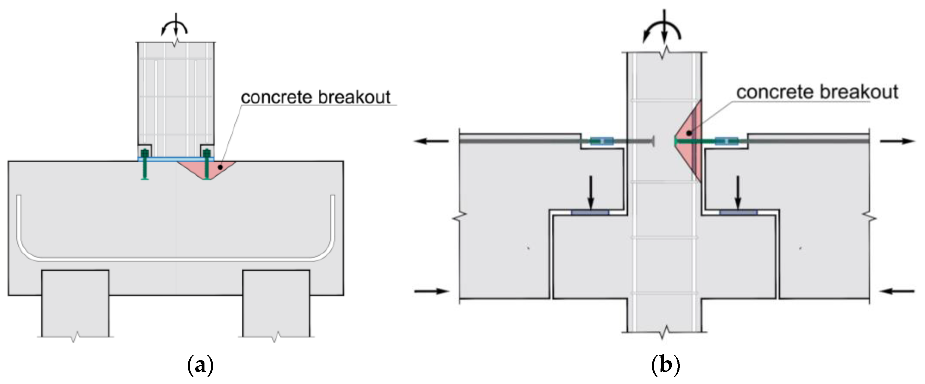
2.2. Concrete Breakout Strength
3. Experimental Program
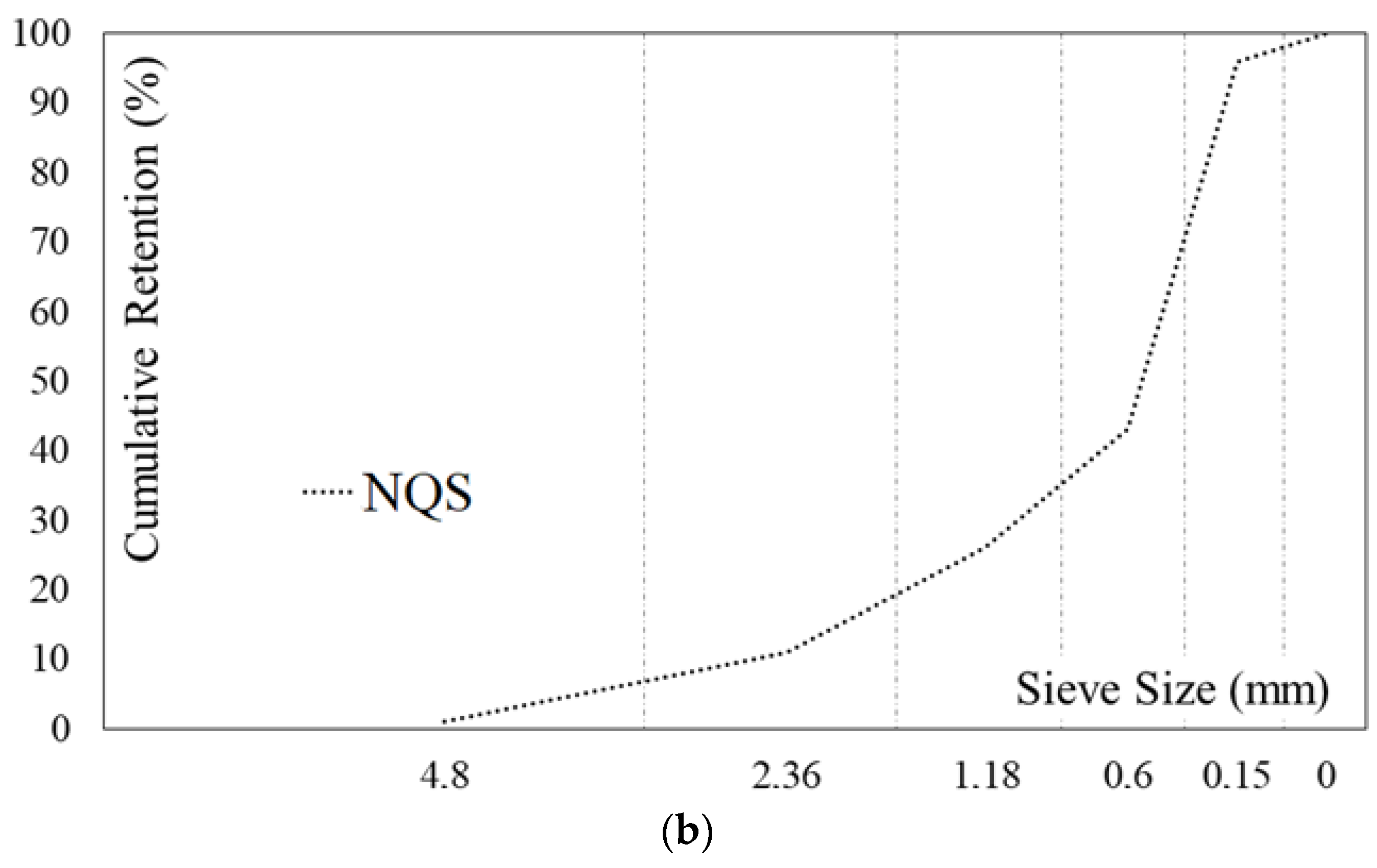
3.1. Materials
3.2. Concrete Production
3.3. Characteristics of Reinforced Concrete Specimens
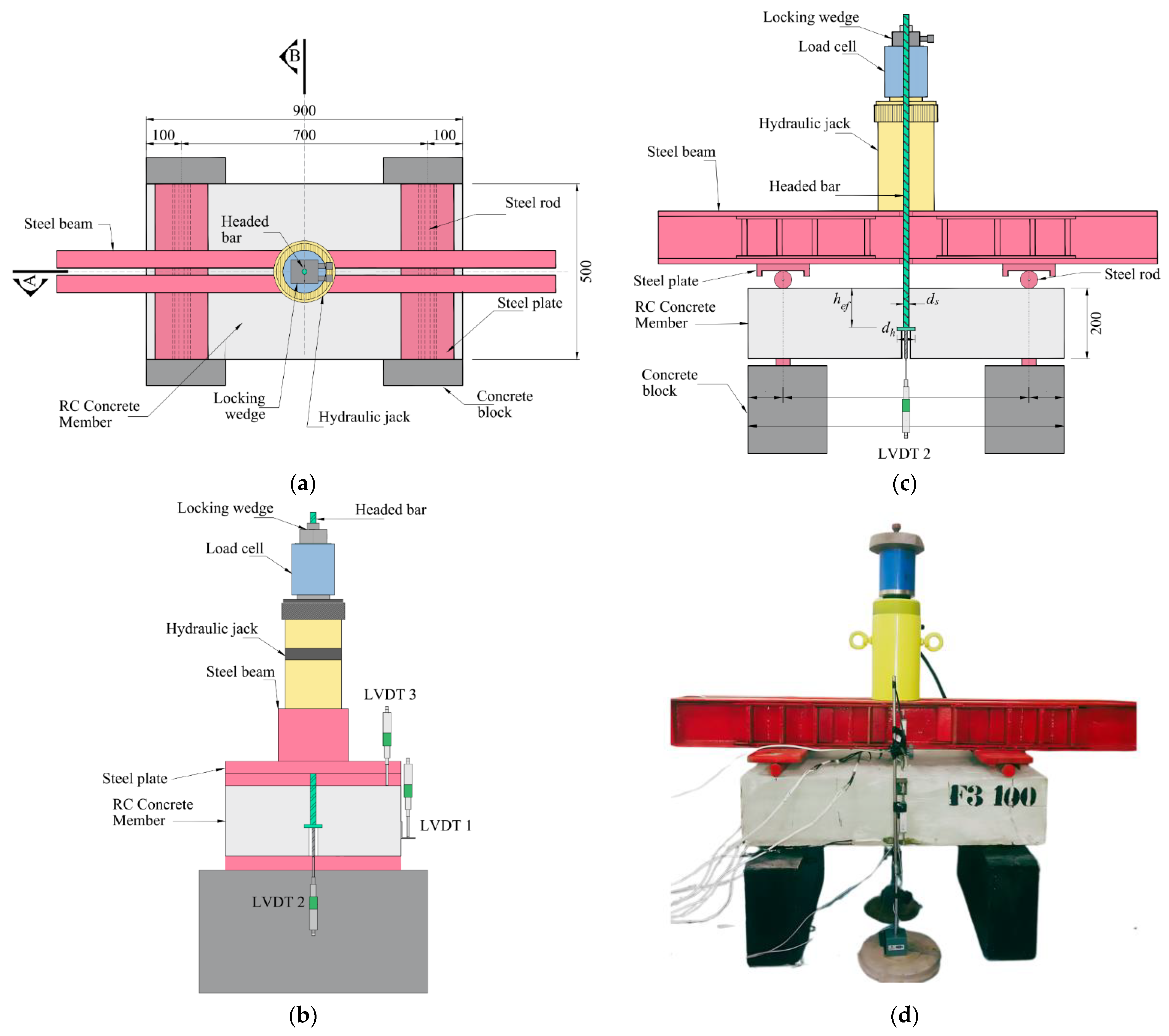
3.4. Instrumentation, Monitoring, and Testing System
4. Results and Discussion
4.1. Effect of RCA and ρf % on Vertical Displacement
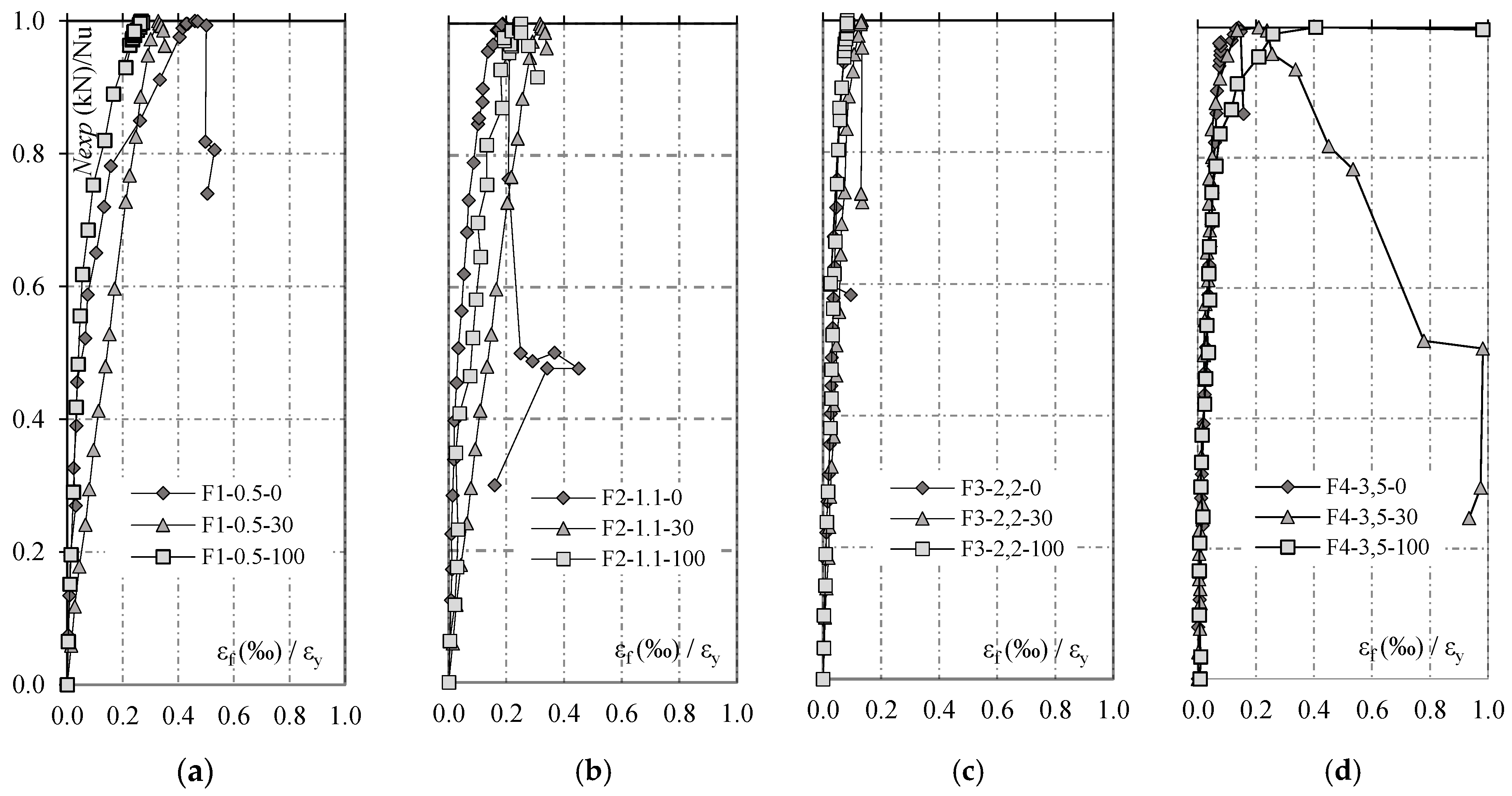
4.2. Strains in the Flexural Reinforcement
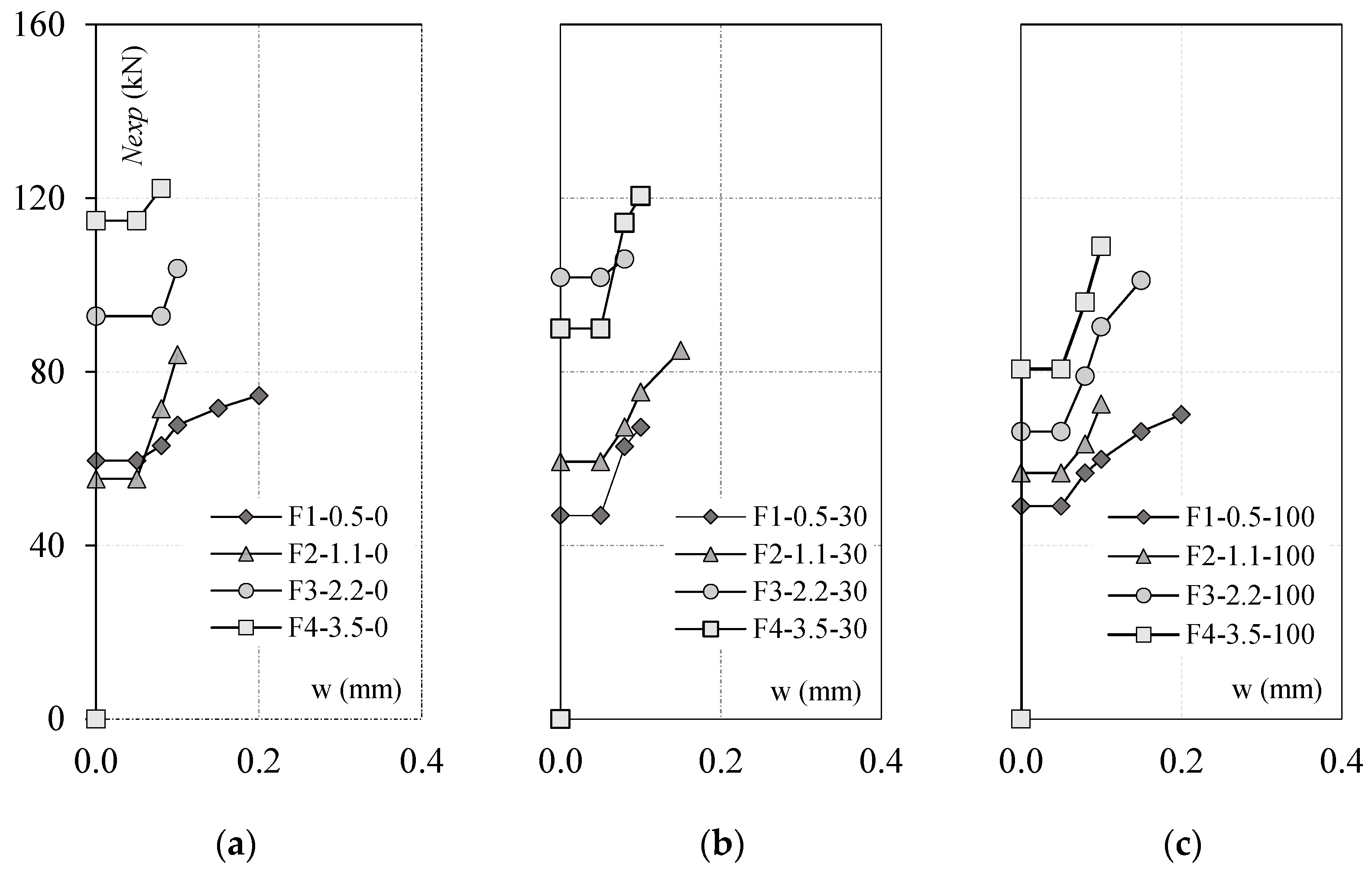
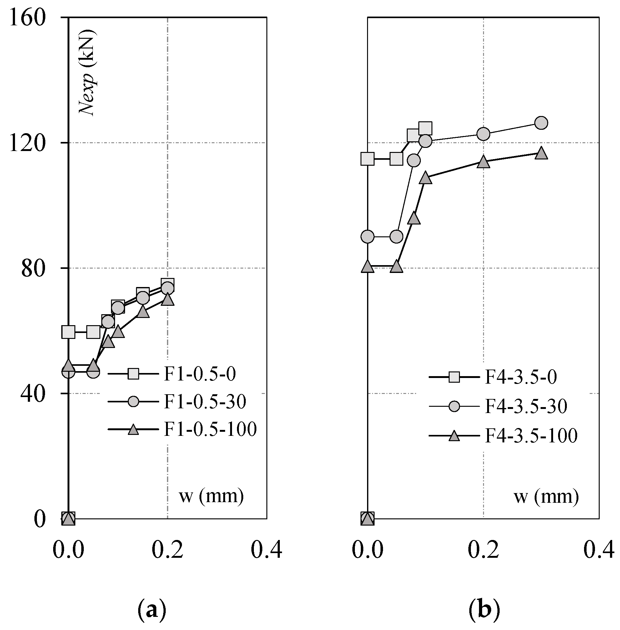
4.3. Effect of RCA and ρf on Crack Width
4.4. Slippage of the Headed Bar
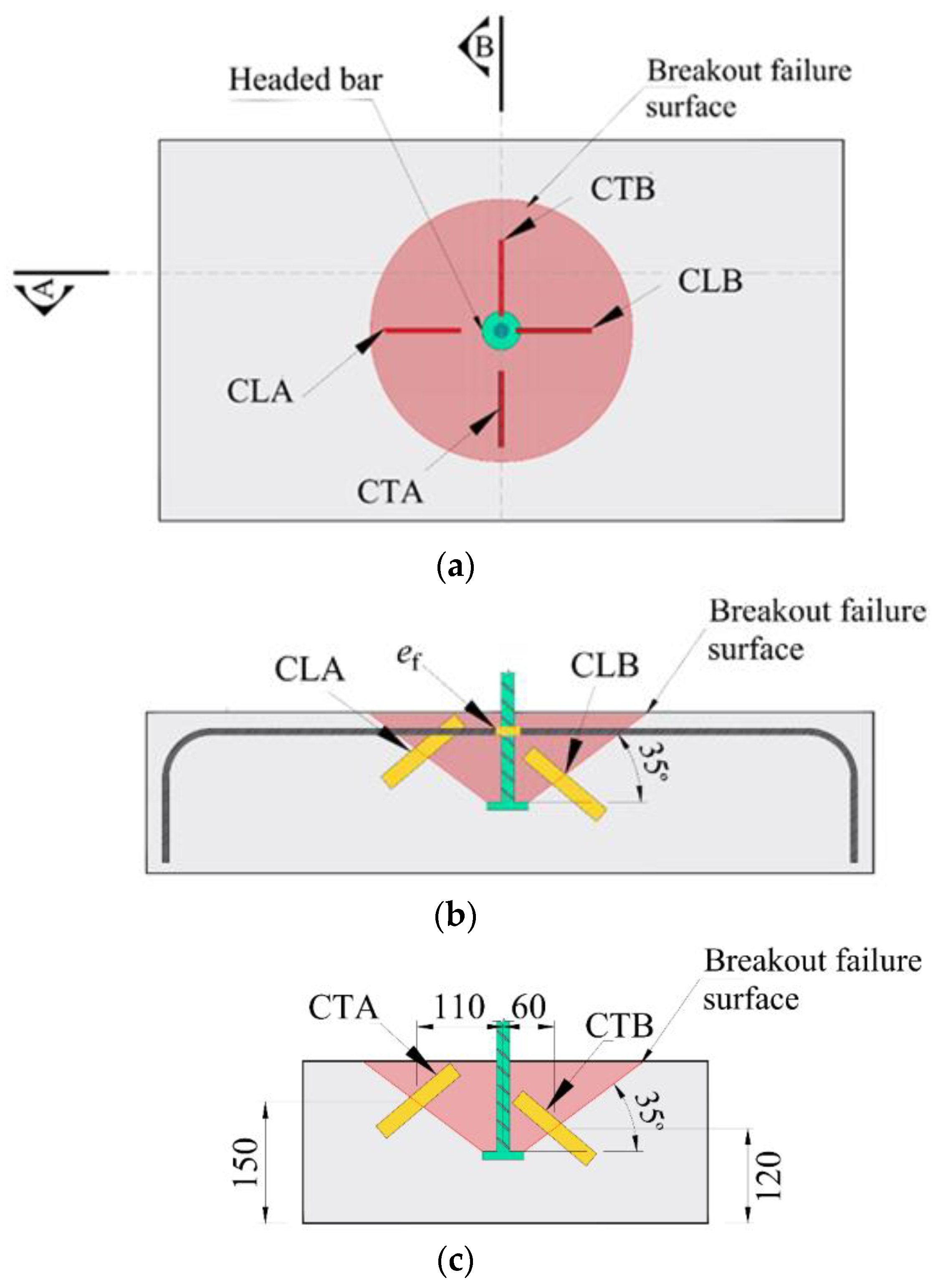
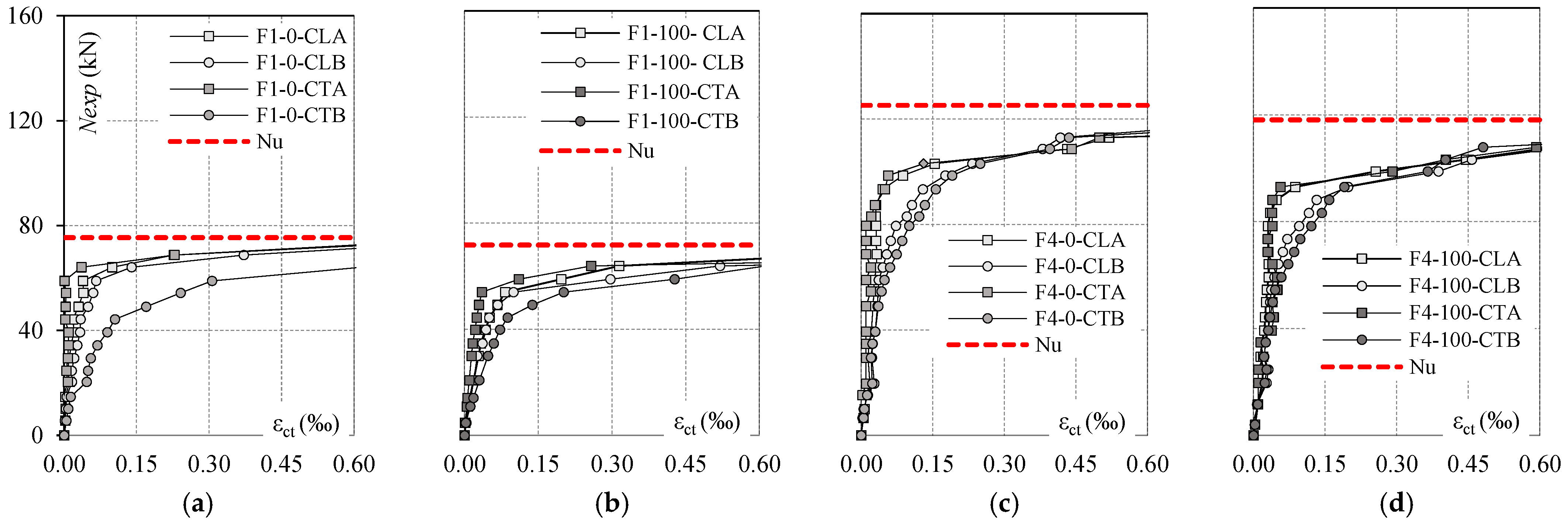
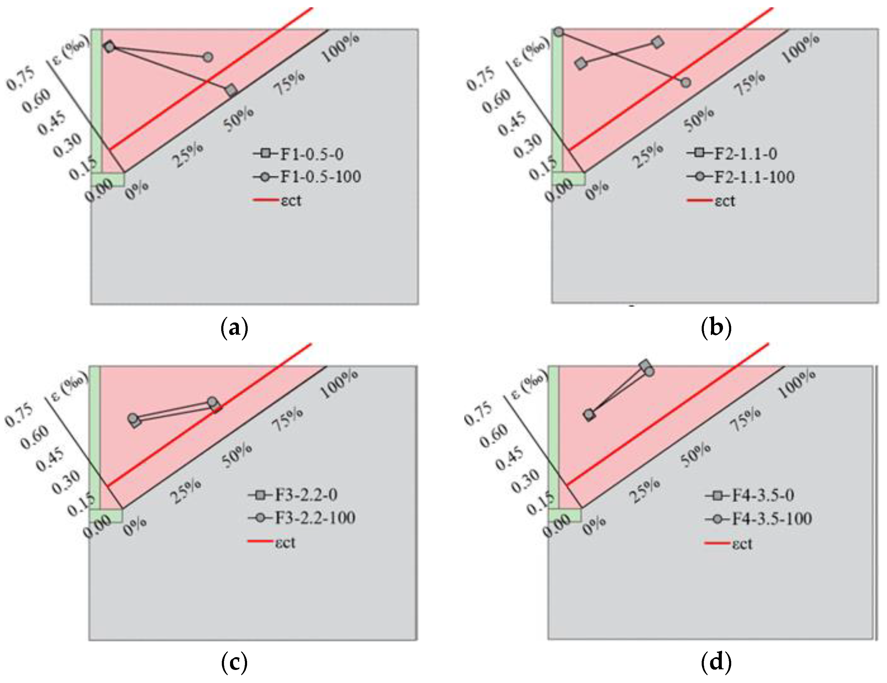
4.5. Effect of RCA on Strains in the Concrete Cone
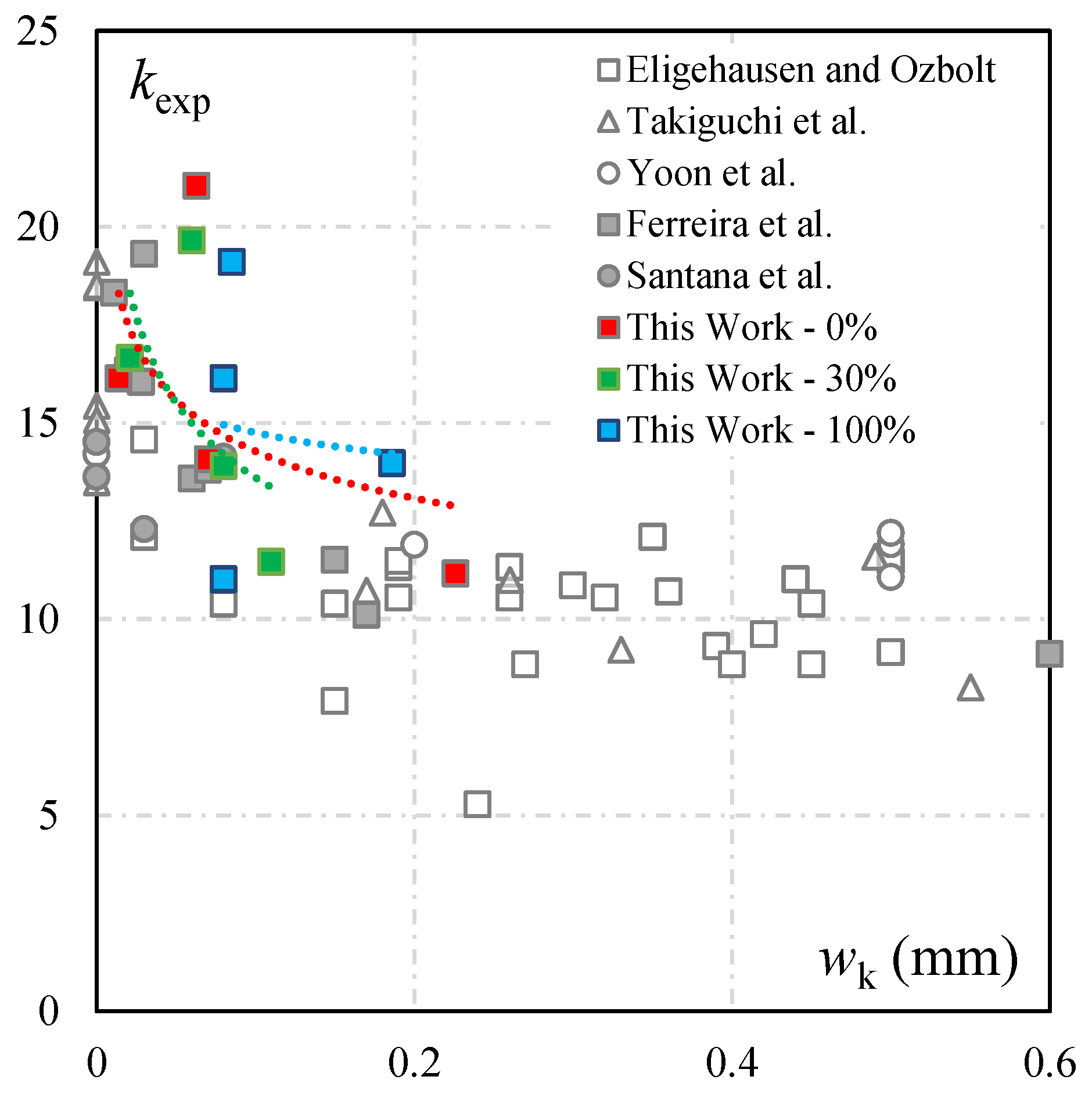
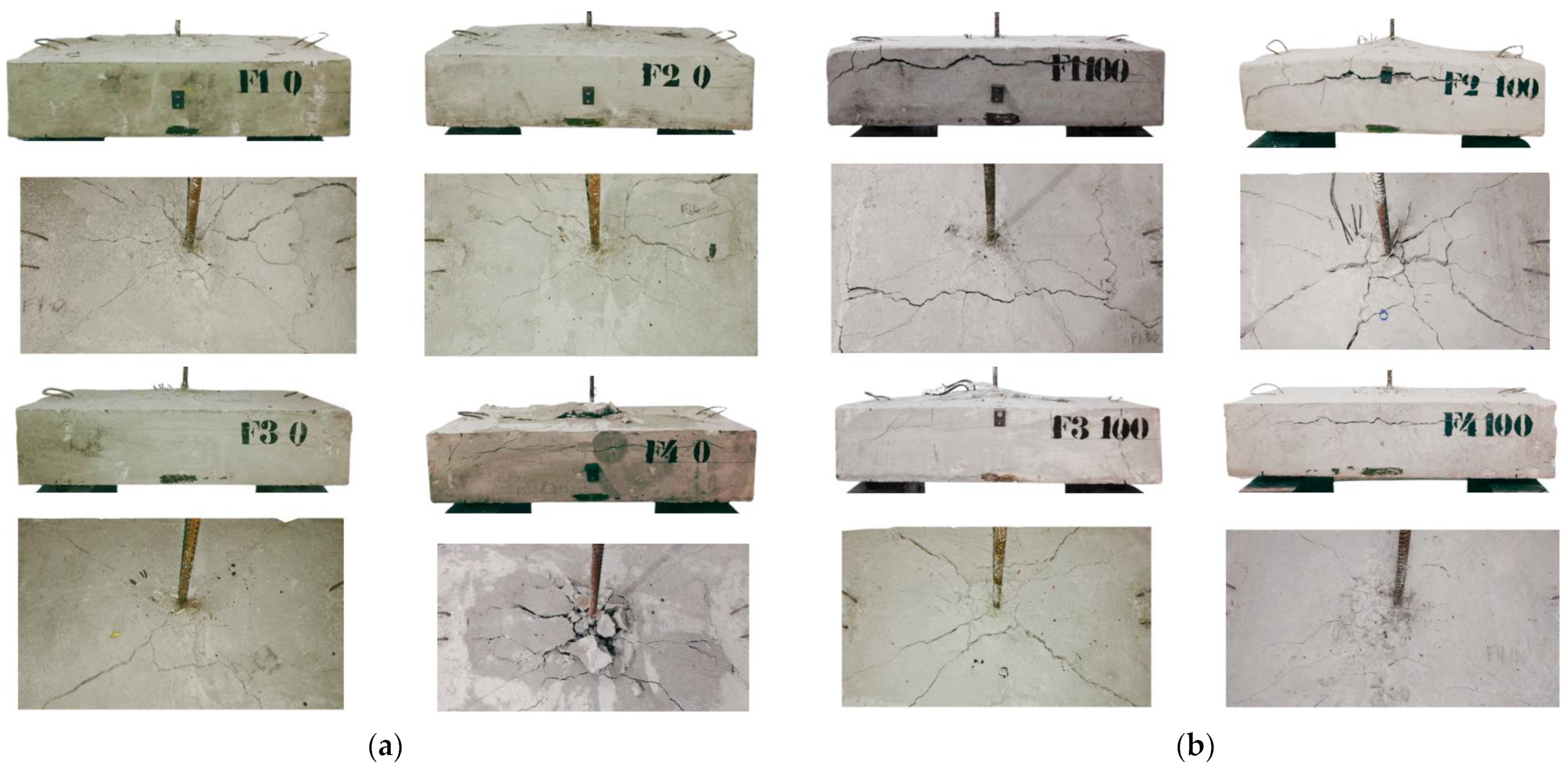
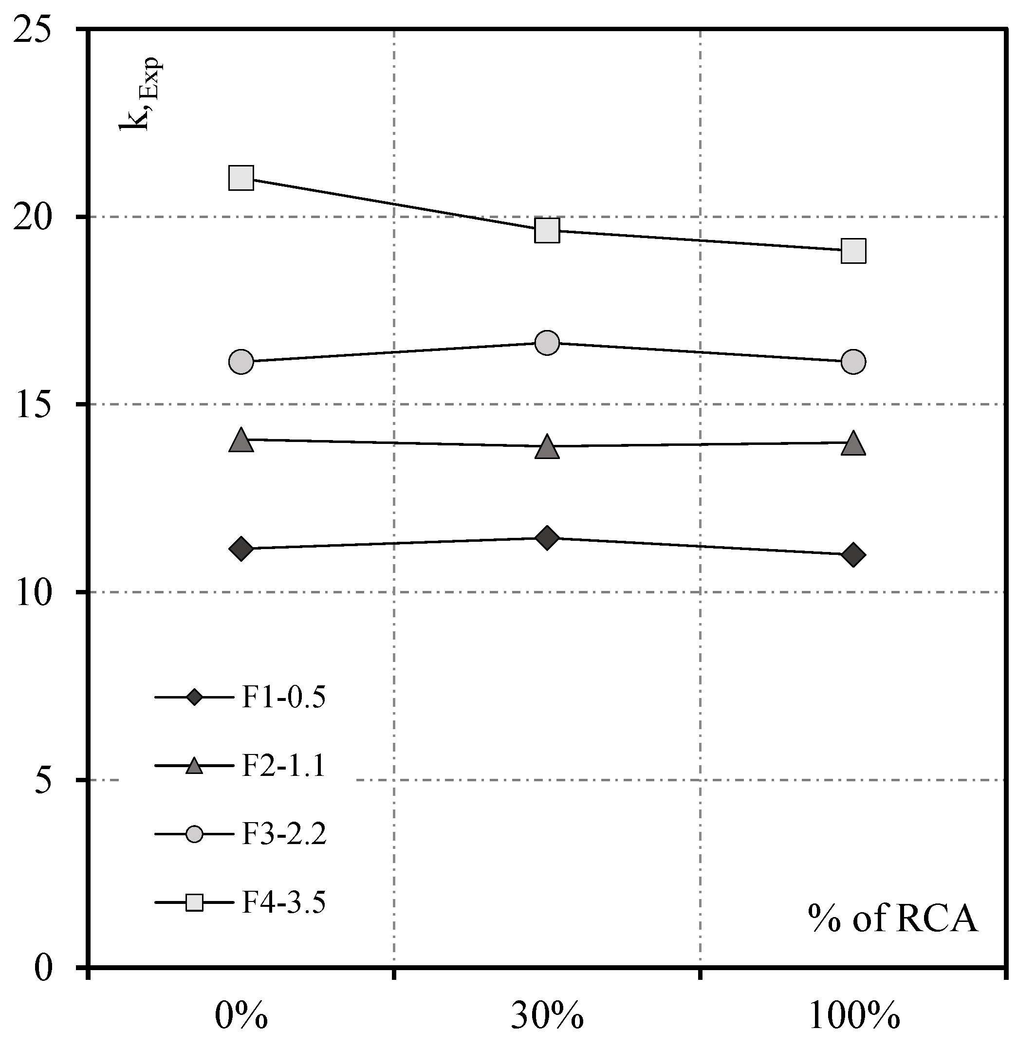
4.6. Effect of RCA in the Concrete Breakout Strength and Failure Modes
5. Conclusions
- Using RCA did not affect the response of headed bars embedded in slender reinforced concrete structural members. On the other hand, increments of the flexural reinforcement ratio significantly affected the response and the concrete breakout strength of the headed bars due to the reduction in crack widths before failure.
- Measuring the internal strains in the projection of the concrete failure cone indicates that the critical crack starts at the anchor’s head and extends towards the concrete surface. Furthermore, increasing the flexural reinforcement ratio controls the crack widths, thus increasing the concrete breakout resistance of the tested headed bars. Furthermore, using RCA did not affect the strains of the concrete cone, regardless of the aggregate replacement percentage.
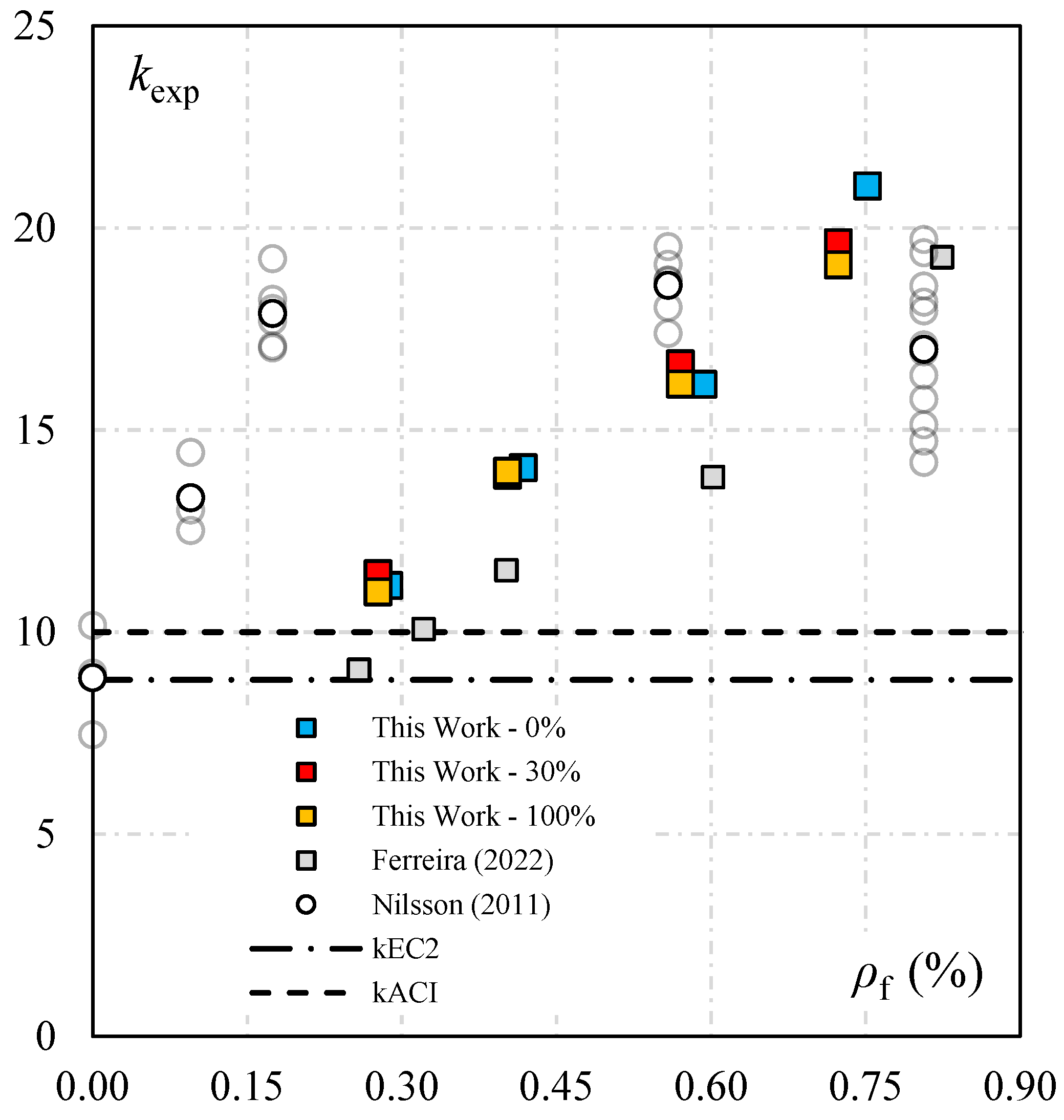
- The concrete breakout strength of the tested headed bars was related not only to the mechanical properties of the concrete and the effective embedment of the anchor but also to the flexural reinforcement ratio of the specimens, regardless of the substitution of natural coarse aggregates by recycled concrete aggregates.
- Using recycled concrete aggregates instead of natural coarse aggregates did not affect the concrete breakout strength of headed bars embedded in slender structural members. These findings indicate that utilizing RCA for structural applications in the precast concrete industry is a feasible alternative, but further scientific research is needed.
Author Contributions
Funding
Data Availability Statement
Conflicts of Interest
Abbreviations
| RCA | coarse recycled concrete aggregate |
| NCA | natural coarse aggregate |
| NQS | natural quartz sand |
| m | unit mass |
| p | unit proportion of fine aggregates |
| pRCA | proportion of coarse recycled concrete aggregate |
| W/C | water–cement ration |
| C | cement consumption |
| d | effective depth of specimen |
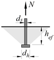
| ds | diameter of the anchor shank |
| dh | diameter of the anchor head |
| fc | concrete compressive strength |
| fct | concrete tensile strength |
| h | height of the concrete specimen |
| hef | embedment depth |
| ef | strain gauge that monitors the flexural reinforcement |
| CLA | strain gauge that monitors the concrete longitudinally near the head of the connector |
| CLB | strain gauge that monitors the concrete longitudinally near the flexural reinforcement |
| CTA | strain gauge that monitors the concrete cross-section near the head of the connector |
| CTB | strain gauge that monitors the concrete cross-section near the flexural reinforcement |
| LVDT | linear variable differential transformer |
| k | coefficient to account for the influence of the cracking state of the concrete in the concrete cone resistance |
| kexp | coefficient measured on tests, calculated as Nu/(fc0.5 ∙ hef1.5) |
| kuncr | coefficient to consider that the anchor was placed on an uncracked concrete zone |
| nf | number of flexural rebars in the tested specimen |
| wk | concrete crack width |
| Eci | modulus of elasticity of the concrete |
| Ef | modulus of elasticity of the flexural reinforcement |
| Nu | tensile strength of an anchor for concrete cone failure |
| Nexp | experimental strength of the specimens |
| δ | displacement of the flexural reinforcement |
| εct | strain on the concrete surface |
| εf | strain on reinforcement steel |
| εy | yield strain of reinforcement steel |
| Øf | diameter of the flexural reinforcement |
| ξ | slip of the headed bars |
| ρf | flexural reinforcement ratio |
References
- Omary, S.; Ghorbel, E.; Wardeh, G. Relationships between recycled concrete aggregates characteristics and recycled aggregates concretes properties. Constr. Build. Mater. 2016, 108, 163–174. [Google Scholar] [CrossRef]
- Koper, A.; Koper, W.; Koper, M. Influence of Raw Concrete Material Quality on Selected Properties of Recycled Concrete Aggregates. Procedia Eng. 2017, 172, 536–543. [Google Scholar] [CrossRef]
- Pedro, D.; De Brito, J.; Evangelista, L. Mechanical characterization of high performance concrete prepared with recycled aggregates and silica fume from precast industry. J. Clean. Prod. 2017, 164, 939–949. [Google Scholar] [CrossRef]
- Salesa, Á.; Pérez-Benedicto, J.Á.; Esteban, L.M.; Vicente-Vas, R.; Orna-Carmona, M. Physico-mechanical properties of multi-recycled self-compacting concrete prepared with precast concrete rejects. Constr. Build. Mater. 2017, 153, 364–373. [Google Scholar] [CrossRef]
- Fiol, F.; Thomas, C.; Muñoz, C.; Ortega-López, V.; Manso, J.M. The influence of recycled aggregates from precast elements on the mechanical properties of structural self-compacting concrete. Constr. Build. Mater. 2018, 182, 309–323. [Google Scholar] [CrossRef]
- Bai, G.; Zhu, C.; Liu, C.; Liu, B. An evaluation of the recycled aggregate characteristics and the recycled aggregate concrete mechanical properties. Constr. Build. Mater. 2020, 240, 117978. [Google Scholar] [CrossRef]
- Berredjem, L.; Arabi, N.; Molez, L. Mechanical and durability properties of concrete based on recycled coarse and fine aggregates produced from demolished concrete. Constr. Build. Mater. 2020, 246, 118421. [Google Scholar] [CrossRef]
- Seara-Paz, S.; González-Fonteboa, B.; Martínez-Abella, F.; Eiras-López, J. Flexural performance of reinforced concrete beams made with recycled concrete coarse aggregate. Eng. Struct. 2018, 156, 32–45. [Google Scholar] [CrossRef]
- Huang, Y.; Xiao, J.; Zhang, C. Theoretical study on mechanical behavior of steel confined recycled aggregate concrete. J. Constr. Steel Res. 2012, 76, 100–111. [Google Scholar] [CrossRef]
- Katkhuda, H.; Shatarat, N. Shear behavior of reinforced concrete beams using treated recycled concrete aggregate. Constr. Build. Mater. 2016, 125, 63–71. [Google Scholar] [CrossRef]
- Malešev, M.; Radonjanin, V.; Marinković, S. Recycled concrete as aggregate for structural concrete production. Sustainability 2010, 2, 1204–1225. [Google Scholar] [CrossRef]
- ACI Committee 318; Building Code Requirements for Structural Concrete (ACI 318-19). ACI: Farmington Hills, MI, USA, 2019.
- Fédération Internationale du Béton. FIB Bulletin 58—Design of Anchorage in Concrete; FIB: Lausanne, Switzerland, 2011. [Google Scholar]
- Eligehausen, R.; Mallée, R.; Silva, J. Anchorage in Concrete Construction, 1st ed.; Ernst & Sohn GmbH & Co.: Hoboken, NJ, USA, 2006. [Google Scholar]
- Nilsson, M.; Ohlsson, U.; Elfgren, L. Effects of surface reinforcement on bearing capacity of concrete with anchor bolts. Cem. Concr. Res. 2018, 44, 161–174. [Google Scholar]
- Ferreira, M.; Filho, M.P.; Lima, N.; Oliveira, M. Influence of the flexural and shear reinforcement in the concrete cone resistance of headed bars. Eng. Struct. 2021, 248, 113212. [Google Scholar] [CrossRef]
- Santana, P.F.; Silva, P.C.; Ferreira, M.P.; Bezerra, L.M.; Oliveira, M.H. Experimental and numerical study of headed bars embedded in RC members under tension. Struct. Eng. Mech. 2022, 84, 531–546. [Google Scholar] [CrossRef]
- Elsayed, M.; Abd-Allah, S.R.; Said, M.; El-Azim, A.A. Structural performance of recycled coarse aggregate concrete beams containing waste glass powder and waste aluminum fibers. Case Stud. Constr. Mater. 2023, 18, e01751. [Google Scholar] [CrossRef]
- Rahal, K.; Alrefaei, Y. Shear strength of longitudinally reinforced recycled aggregate concrete beams. Eng. Struct. 2017, 145, 273–282. [Google Scholar] [CrossRef]
- McNeil, K.; Kang, T.H.-K. Recycled Concrete Aggregates: A Review. Int. J. Concr. Struct. Mater. 2013, 7, 61–69. [Google Scholar] [CrossRef]
- Akbarnezhad, A.; Ong, K.C.G. Separation processes to improve the quality of recycled concrete aggregates (RCA). In Handbook of Recycled Concrete and Demolition Waste; Elsevier Inc.: Amsterdam, The Netherlands, 2013; pp. 246–269. [Google Scholar] [CrossRef]
- Saravanakumar, P.; Abhiram, K.; Manoj, B. Properties of treated recycled aggregates and its influence on concrete strength characteristics. Constr. Build. Mater. 2016, 111, 611–617. [Google Scholar] [CrossRef]
- Kubissa, W.; Jaskulski, R.; Koper, A.; Szpetulski, J. Properties of concretes with natural aggregate improved by RCA addition. Procedia Eng. 2015, 108, 30–38. [Google Scholar] [CrossRef]
- Behera, M.; Bhattacharyya, S.; Minocha, A.; Deoliya, R.; Maiti, S. Recycled aggregate from C&D waste & its use in concrete—A breakthrough towards sustainability in construction sector: A review. Constr. Build. Mater. 2014, 68, 501–516. [Google Scholar] [CrossRef]
- Hansen, T.C. Recycled aggregate and recycled aggregate concrete, second state of- the-art report, developments from 1945–1985. Mater. Struct. 1986, 19, 201–246. [Google Scholar] [CrossRef]
- Casuccio, M.; Torrijos, M.; Giaccio, G.; Zerbino, R. Failure mechanism of recycled aggregate concrete. Constr. Build. Mater. 2008, 22, 1500–1506. [Google Scholar] [CrossRef]
- Padmini, A.K.; Ramamurthy, K.; Mathews, M.S. Influence of parent concrete on the properties of recycled aggregate concrete. Constr. Build. Mater. 2009, 23, 829–836. [Google Scholar] [CrossRef]
- Cabral, A.E.B.; Schalch, V.; Molin, D.C.C.D.; Ribeiro, J.L.D. Mechanical properties modeling of recycled aggregate concrete. Constr. Build. Mater. 2010, 24, 421–430. [Google Scholar] [CrossRef]
- Paine, K.; Dhir, R. Recycled aggregates in concrete: A performance-related approach. Mag. Concr. Res. 2010, 62, 519–530. [Google Scholar] [CrossRef]
- Limbachiya, M.C.; Leelawat, T.; Dhir, R.K. Use of recycled concrete aggregate in high-strength concrete. Mater. Struct. 2000, 33, 574–580. [Google Scholar] [CrossRef]
- Çakir, O. Experimental analysis of properties of recycled coarse aggregate (RCA) concrete with mineral additives. Constr. Build. Mater. 2014, 68, 17–25. [Google Scholar] [CrossRef]
- Silva, R.; de Brito, J.; Dhir, R. Tensile strength behaviour of recycled aggregate concrete. Constr. Build. Mater. 2015, 83, 108–118. [Google Scholar] [CrossRef]
- Xiao, J.; Li, J.; Zhang, C. Mechanical properties of recycled aggregate concrete under uniaxial loading. Cem. Concr. Res. 2005, 35, 1187–1194. [Google Scholar] [CrossRef]
- Gomes, M.; de Brito, J. Structural concrete with incorporation of coarse recycled concrete and ceramic aggregates: Durability performance. Mater. Struct. 2009, 42, 663–675. [Google Scholar] [CrossRef]
- Eligehausen, R.; Sawade, G. A Fracture Mechanics Based Description of the Pull-Out Behavior of Headed Studs Embedded in Concrete, Elfgren, Lennart (Hrsg.): Fracture Mechanics of Concrete Structures; Chapman and Hall: London, UK, 1989; pp. 281–299. ISBN 0-412-30680-8. [Google Scholar]
- Eligehausen, R. Behavior, Design and Testing of Anchors in Cracked Concrete. ACI Struct. J. 1992, 130, 123–176. [Google Scholar]
- Ozbolt, J.; Eligehausen, R. Numerical Analysis of Headed Studs embedded in Large Plain Concrete Blocks. In Proceedings of the 2nd International Conference of Computer Aided Analysis and Design of Concrete Structures, Zell am See, Austria, 4–6 April 1990. [Google Scholar]
- Di Nunzio, G.; Muciaccia, G. Cast-in-place fasteners under tensile loading: A critical review. Structures 2022, 41, 1532–1545. [Google Scholar] [CrossRef]
- Karmokar, T.; Mohyeddin, A.; Lee, J.; Paraskeva, T. Concrete cone failure of single cast-in anchors under tensile loading. Eng. Struct. 2021, 243, 112615. [Google Scholar] [CrossRef]
- Helene, P.; Terzian, P. Manual de Dosagem e Controle do Concreto; PINI: São Paulo, Brazil, 1993; p. 349. [Google Scholar]
- Fédération Internationale du Béton. FIB Model Code for Concrete Structures; FIB: Lausanne, Switzerland, 2010; Volume 2013, p. 402. [Google Scholar]
- Takiguchi, K.; Harada, R.; Ishizeki, K. Pull out Strength an Anchor Bolt Embedded in Cracked Concrete. In Proceedings of the 15th International Conference on Structural Mechanics in Reactor Technology, Seoul, Republic of Korea, 15–20 August 1999; pp. 305–310. [Google Scholar]
- Yoon, Y.S.; Kim, H.S.; Kim, S.Y. Assessment of fracture behaviors for CIP anchors fastened to cracked e uncracked concrete. Int. J. Concr. Struct. Mater. 2001, 13, 33–41. [Google Scholar]


| Notation | Factor k | fib Bull. 58 | ACI 318-19 |
|---|---|---|---|
 | k1 for uncracked concrete | 12.7 | 12.5 for hef < 280 mm 4.9 for 280 mm ≤ hef < 635 mm |
| k1 for cracked concrete | 8.9 | 10.0 for hef < 280 mm 3.9 for 280 mm ≤ hef < 635 mm | |
| n | 3/2 | 3/2 hef < 280 mm 5/3 for 280 mm ≤ hef < 635 mm |
| Natural Quartz Sand | Natural Coarse Aggregate | Recycled Concrete Aggregate | |
|---|---|---|---|
| Fineness modulus | 2.61 | 7.00 | 6.96 |
| Maximum aggregate size (mm) | 4.80 | 25.4 | 25.4 |
| Density (g/cm3) | 2.61 | 2.62 | 2.66 |
| Bulk density (g/cm3) | 1.67 | 1.34 | 1.11 |
| % of RCA | Unit Mix Proportion | W/C | C | |||
|---|---|---|---|---|---|---|
| m | a | p | pRCA | (kg/m³) | ||
| 0 | 5.3 | 2.21 | 3.09 | - | 0.59 | 342.5 |
| 30 | 5.1 | 2.11 | 2.09 | 0.9 | 0.60 | 343.8 |
| 100 | 5.2 | 2.16 | - | 3.04 | 0.65 | 337.2 |
| Specimen | % of RCA | d mm | hef mm | Flexural Reinforcement | Concrete | ||||||
|---|---|---|---|---|---|---|---|---|---|---|---|
| nf | Øf | fy,f | Ef | ρf | fc | fct | Eci | ||||
| N1 | (mm) | (MPa) | (GPa) | (%) | (MPa) | (MPa) | (GPa) | ||||
| F1-0.5-0 | 0 | 175 | 119 | 6 | 10.0 | 590.3 | 198 | 0.5 | 27.1 | 3.2 | 20.3 |
| F2-1.1-0 | 174 | 115 | 8 | 12.5 | 590.3 | 196 | 1.1 | 25.2 | 3.0 | 20.8 | |
| F3-2.2-0 | 170 | 120 | 6 | 20.0 | 506.7 | 190 | 2.2 | 27.1 | 3.2 | 20.3 | |
| F4-3.5-0 | 168 | 112 | 6 | 25.0 | 527.4 | 205 | 3.5 | 25.2 | 3.0 | 20.8 | |
| F1-0.5-30 | 30 | 175 | 116 | 6 | 10.0 | 590.3 | 198 | 0.5 | 26.6 | 3.0 | 20.3 |
| F2-1.1-30 | 174 | 117 | 8 | 12.5 | 590.3 | 196 | 1.1 | 26.9 | 3.1 | 20.5 | |
| F3-2.2-30 | 170 | 115 | 6 | 20.0 | 506.7 | 190 | 2.2 | 26.9 | 3.1 | 20.5 | |
| F4-3.5-30 | 168 | 117 | 6 | 25.0 | 527.4 | 205 | 3.5 | 26.6 | 3.0 | 20.3 | |
| F1-0.5-100 | 100 | 175 | 116 | 6 | 10.0 | 590.3 | 198 | 0.5 | 27.2 | 2.7 | 17.4 |
| F2-1.1-100 | 174 | 113 | 8 | 12.5 | 590.3 | 196 | 1.1 | 25.3 | 2.7 | 16.7 | |
| F3-2.2-100 | 170 | 118 | 6 | 20.0 | 506.7 | 190 | 2.2 | 25.3 | 2.7 | 16.7 | |
| F4-3.5-100 | 168 | 112 | 6 | 25.0 | 527.4 | 205 | 3.5 | 27.2 | 2.7 | 17.4 | |
| Specimen | % of RCA | hef mm | ρf % | Nexp (kN) | λfib | λACI |
|---|---|---|---|---|---|---|
| F1-0.5-0 | 0 | 119 | 0.5 | 75.4 | 1.25 | 1.12 |
| F2-1.1-0 | 115 | 1.1 | 87.1 | 1.58 | 1.41 | |
| F3-2.2-0 | 120 | 2.2 | 110.4 | 1.81 | 1.61 | |
| F4-3.5-0 | 112 | 3.5 | 125.2 | 2.36 | 2.10 | |
| F1-0.5-30 | 30 | 116 | 0.5 | 73.8 | 1.29 | 1.14 |
| F2-1.1-30 | 117 | 1.1 | 91.2 | 1.56 | 1.39 | |
| F3-2.2-30 | 115 | 2.2 | 106.5 | 1.87 | 1.66 | |
| F4-3.5-30 | 117 | 3.5 | 128.2 | 2.21 | 1.96 | |
| F1-0.5-100 | 100 | 116 | 0.5 | 71.7 | 1.24 | 1.10 |
| F2-1.1-100 | 113 | 1.1 | 84.4 | 1.57 | 1.40 | |
| F3-2.2-100 | 118 | 2.2 | 104.0 | 1.81 | 1.61 | |
| F4-3.5-100 | 112 | 3.5 | 118.1 | 2.15 | 1.91 |
Disclaimer/Publisher’s Note: The statements, opinions and data contained in all publications are solely those of the individual author(s) and contributor(s) and not of MDPI and/or the editor(s). MDPI and/or the editor(s) disclaim responsibility for any injury to people or property resulting from any ideas, methods, instructions or products referred to in the content. |
© 2024 by the authors. Licensee MDPI, Basel, Switzerland. This article is an open access article distributed under the terms and conditions of the Creative Commons Attribution (CC BY) license (https://creativecommons.org/licenses/by/4.0/).
Share and Cite
Ferreira, M.d.P.; Santos, K.D.d.; Pereira Filho, M.J.M.; Cordeiro, L.d.N.P. Effect of Recycled Concrete Aggregates on the Concrete Breakout Resistance of Headed Bars Embedded in Slender Structural Elements. Buildings 2024, 14, 2102. https://doi.org/10.3390/buildings14072102
Ferreira MdP, Santos KDd, Pereira Filho MJM, Cordeiro LdNP. Effect of Recycled Concrete Aggregates on the Concrete Breakout Resistance of Headed Bars Embedded in Slender Structural Elements. Buildings. 2024; 14(7):2102. https://doi.org/10.3390/buildings14072102
Chicago/Turabian StyleFerreira, Maurício de Pina, Karoline Dantas dos Santos, Manoel José Mangabeira Pereira Filho, and Luciana de Nazaré Pinheiro Cordeiro. 2024. "Effect of Recycled Concrete Aggregates on the Concrete Breakout Resistance of Headed Bars Embedded in Slender Structural Elements" Buildings 14, no. 7: 2102. https://doi.org/10.3390/buildings14072102
APA StyleFerreira, M. d. P., Santos, K. D. d., Pereira Filho, M. J. M., & Cordeiro, L. d. N. P. (2024). Effect of Recycled Concrete Aggregates on the Concrete Breakout Resistance of Headed Bars Embedded in Slender Structural Elements. Buildings, 14(7), 2102. https://doi.org/10.3390/buildings14072102