
Investigations on the Environmental Characteristics and Cracking Control of Plateau Concrete


 , and
, and
Abstract
:1. Introduction
2. Environmental Characteristics
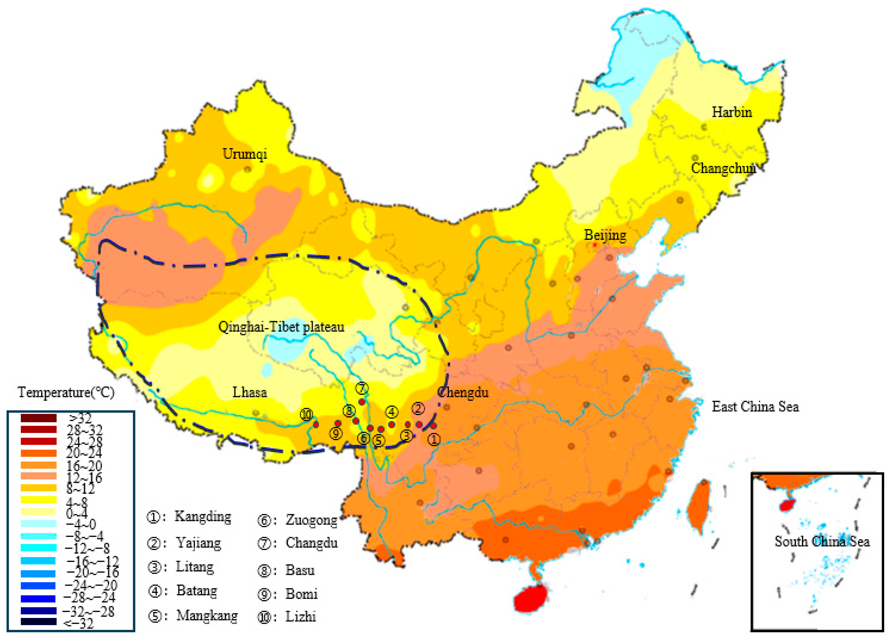
2.1. Temperature and Wind Speed
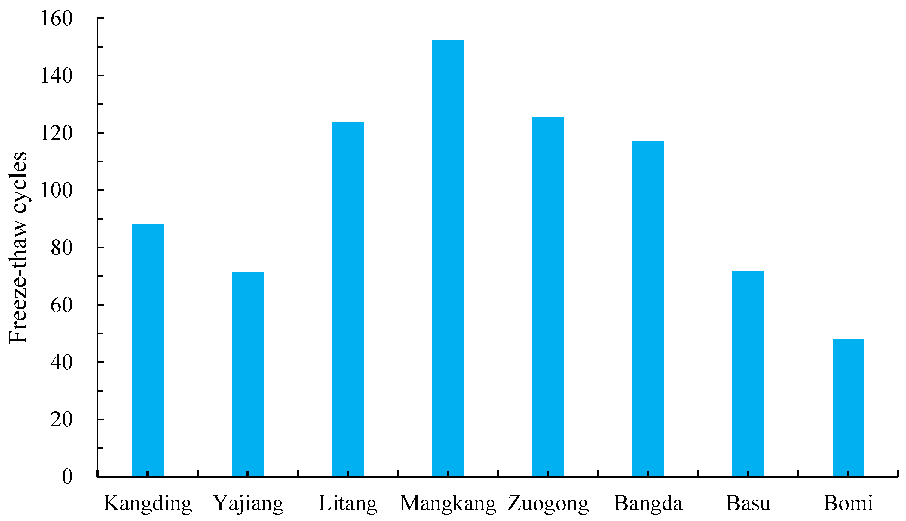
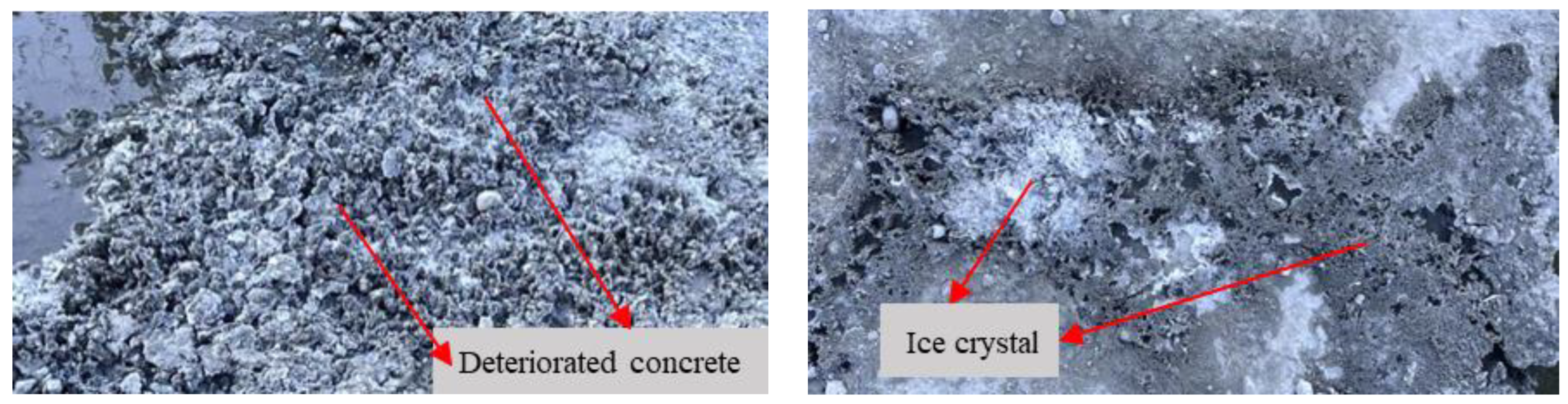
2.2. Severe Freeze–Thaw Cycles
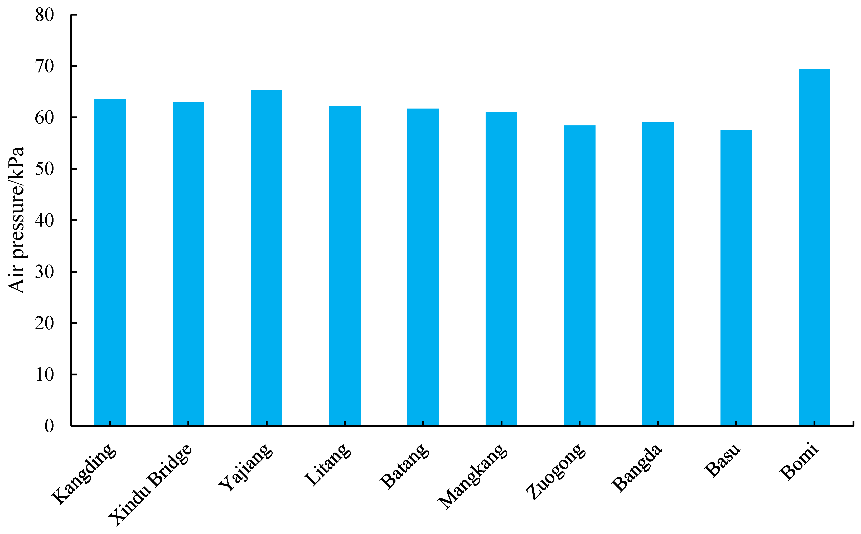
2.3. Low Air Pressure
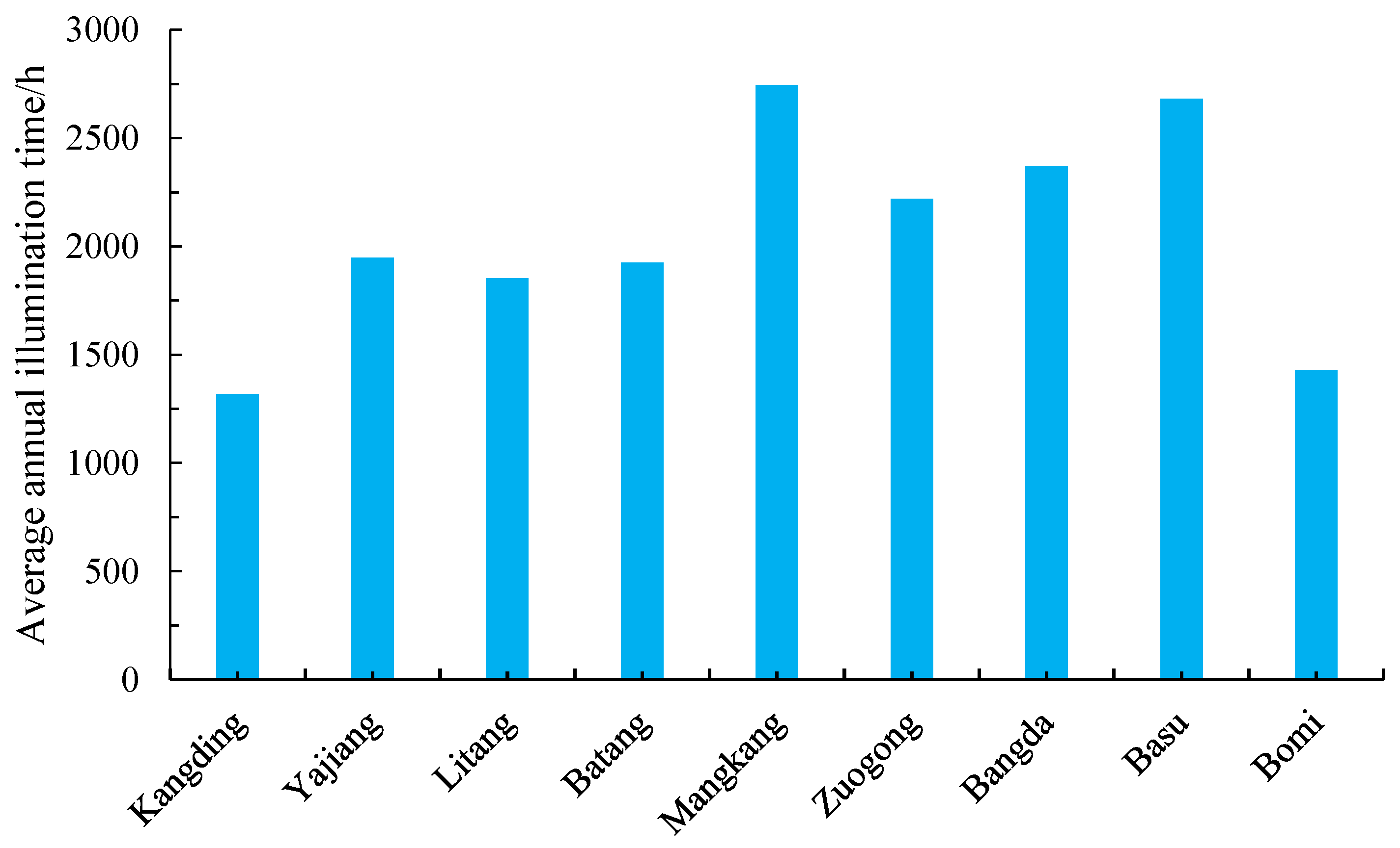
2.4. Light Intensity and Temperature Differences
2.5. Dynamic Disturbance
2.6. Other Factors
3. Investigation of Concrete Cracking
3.1. On-Site Cracking Investigation
3.2. Risk Analysis of Cracking
4. Cracking Control Measures
4.1. Increase Deformation Compensation
4.2. Radiation Refrigeration Technology
4.3. Improve Construction Technology
4.4. Improve Management Measures
5. Conclusions
- (1)
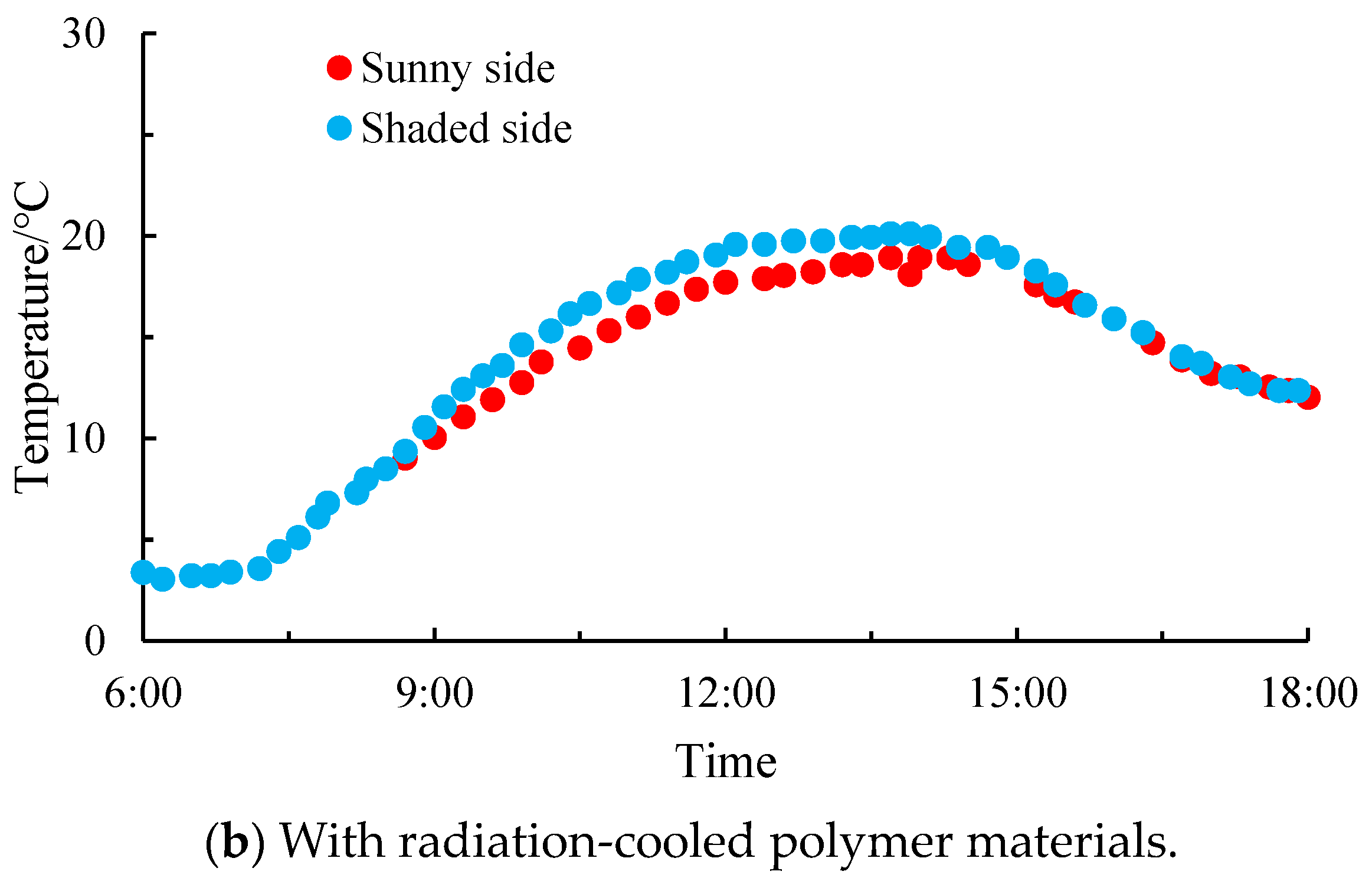
- Various factors such as the temperature, wind speed, freeze–thaw cycles, air pressure, lighting conditions, temperature differentials between sunny and shady sides and dynamic disturbances significantly affected the durability and service performance of the plateau concrete. These factors usually led to different types of cracking in the vertical, longitudinal and transverse directions of the bridge piers. Vertical cracks in the straight section of the pier body are the most common type of crack.
- (2)
- The risk of concrete cracking in the core of a plateau pier body was influenced by factors such as the tensile strength of the concrete, pouring interval age and insulation temperature rise. The long-term cracking risk of the core of the plateau pier was significantly higher compared with the early cracking risk. To mitigate this risk, it is necessary to optimize the concrete mix ratio, regulate the insulation temperature rise and carefully manage the pouring interval age. Through these measures, it is possible to ensure that the early cracking risk coefficient for pier concrete remains below 0.7 and that the long-term cracking risk coefficient does not exceed 1.0.
- (3)
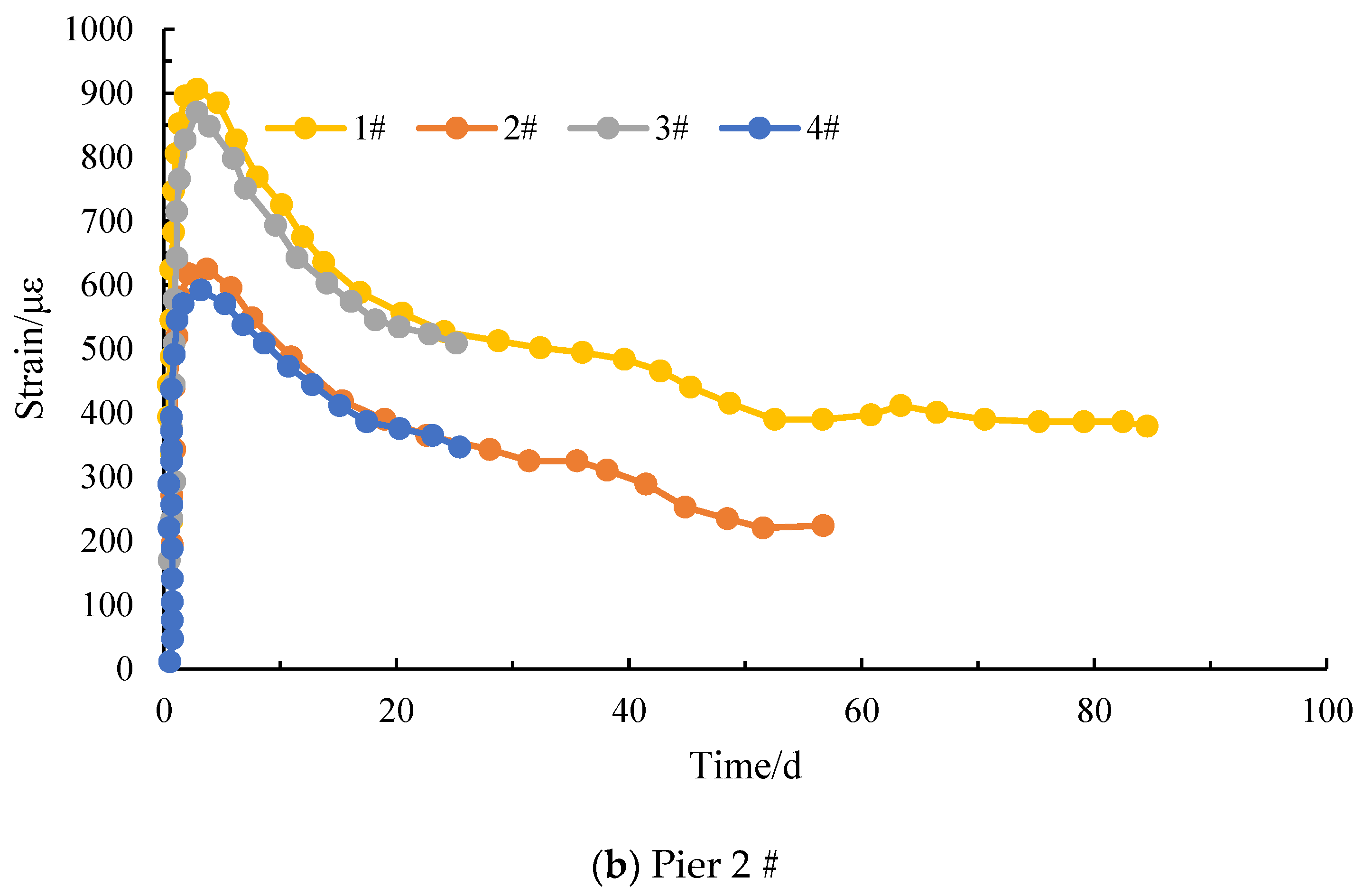
- Deformation compensation can significantly enhance the peak and residual deformation capacities of plateau concrete, with peak values greater than 900 με and residual deformation greater than 200 με at day 60, which greatly reduced the possibility of early and long-term cracking of plateau concrete.
- (4)
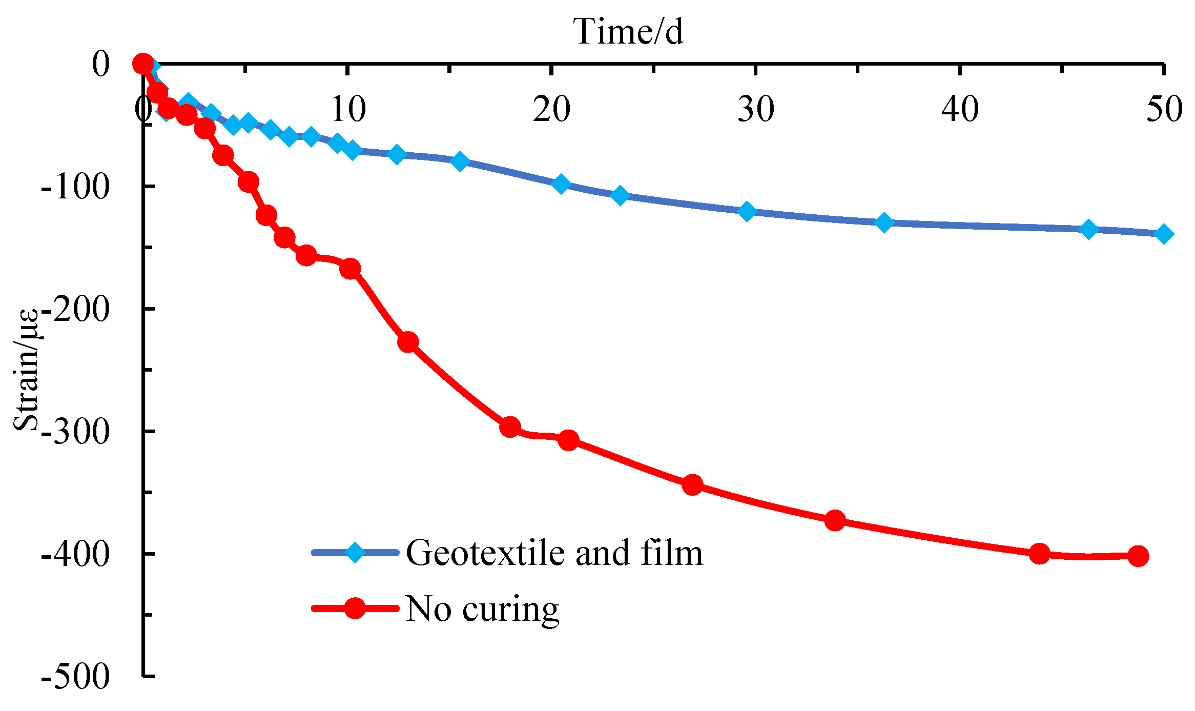
- The implementation of radiation cooling technologies, advances in construction techniques and effective management practices can help to mitigate cracking in high-altitude concrete. However, further research is needed to fully understand the effects of air pressure, high-frequency freeze–thaw cycles and other factors on the degradation of plateau concrete.
Author Contributions
Funding
Data Availability Statement
Acknowledgments
Conflicts of Interest
References
- He, R.; Wang, T.; Cheng, X.H.; Xue, C.; Bai, H.Y. Impact of Qinghai-Tibet plateau’s climate on strength and permeability of concrete. China J. Highw. Transp. 2020, 33, 29–41. [Google Scholar]
- Li, Y.; Wang, Z.D.; Xue, C.; Bai, Y.H.; Wang, L. Influence of low air pressure on the performance of concrete in road engineering. China J. Highw. Transp. 2021, 34, 194–202. [Google Scholar]
- Hu, Y.B.; Cao, R.P. Differences of internal and external structural properties of concrete in the plateau area. Bull. Chin. Ceram. Soc. 2017; 36, 213–218. (In Chinese) [Google Scholar]
- Li, X.F.; Fu, Z.; Luo, Z.; Ke, G.J. Effect of low-pressure in plateau environment on air content of fresh concrete. J. Southeast Univ. (Nat. Sci. Ed.) 2014, 44, 1046–1051. (In Chinese) [Google Scholar]
- Ge, X.; Ge, Y.; Du, Y. Effect of low air pressure on mechanical properties and shrinkage of concrete. Mag. Concrete Res. 2018, 70, 919–927. [Google Scholar] [CrossRef]
- Ge, X.; Ge, Y.; Li, Q.F. Effect of low air pressure on the durability of concrete. Constr. Build. Mater. 2018, 187, 830–838. [Google Scholar] [CrossRef]
- Shi, Y.; Yang, H.Q.; Zhou, S.H.; Wang, A.G.; Lv, X.D. Effect of atmospheric pressure on performance of AEA and air entraining concrete. Adv. Mater. Sci. Eng. 2018, 1–7. [Google Scholar] [CrossRef]
- Huo, J.Y.; Wang, Z.J.; Chen, H.X.; He, R. Impacts of low atmospheric pressure on properties of cement concrete in plateau areas: A literature review. Materials 2019, 12, 1384. [Google Scholar] [CrossRef]
- Zeng, X.H.; Lan, X.L.; Zhu, H.S.; Long, G.C.; Xie, Y.J. Investigation on air-voids structure and compressive strength of concrete at low atmospheric pressure. Cement Concrete Comp. 2021, 122, 104139. [Google Scholar] [CrossRef]
- Mi, L.; Mao, J.H.; Li, L.; Shi, Q.; Fang, K.; Li, S.L.; Deng, X.; Li, G. Microstructural damage and durability of plateau concrete: Insights into freeze-thaw resistance and improvement strategies. Structures 2024, 60, 105888. [Google Scholar] [CrossRef]
- Qin, Y.H.; Ma, H.Y.; Zhang, L.L.; Yin, J.S.; Zheng, X.H.; Li, S. Quantification of the concrete freeze–thaw environment across the Qinghai–Tibet Plateau based on machine learning algorithms. J. Mt. Sci. 2024, 21, 322–334. [Google Scholar] [CrossRef]
- Zhang, R.L.; Long, Z.F.; Long, G.C.; Guo, H.Z.; Zhang, F.J.; Zhang, X.P. Investigating concrete performance: Compressive strength and pore-structure evolution in simulated permafrost conditions of the Qinghai–Tibet Plateau zone. J. Mater. Civ. Eng. 2024, 36, 04024063. [Google Scholar] [CrossRef]
- Lu, C.F.; Cai, C.X. Challenges and countermeasures for construction safety during the Sichuan–Tibet railway project. Engineering 2019, 5, 833–838. [Google Scholar] [CrossRef]
- Chen, Z.; Chen, B.; Zheng, J.L.; Liu, J.P.; Ye, Z.X.; Wu, C.J.; Xu, W. Methodology on evaluating the compactness of core concrete in CFST serving under low atmospheric pressure over the Qinghai-Tibet plateau. China Civ. Eng. J. 2021, 54, 1–13. (In Chinese) [Google Scholar]
- Powers, T.C. A working hypothesis for further studies of frost resistance of concrete. J. Am. Concr. Inst. 1945, 16, 245–272. [Google Scholar]
- Qin, X.C.; Meng, S.P.; Cao, D.F.; Tu, Y.M.; Sabourova, N.; Grip, N.; Ohlsson, U.; Blanksvärd, T.; Sas, G.; Elfgren, L. Evaluation of freeze-thaw damage on concrete material and prestressed concrete specimens. Construct Build. Mater. 2016, 125, 892–904. [Google Scholar] [CrossRef]
- Li, X.F.; Fu, Z. Effect of low-pressure of environment on air content and bubble stability of concrete. J. Chin. Ceram. Soc. 2015, 43, 1076–1082. [Google Scholar]
- Lan, X.L.; Zeng, X.H.; Zhu, H.S.; Long, G.C.; Xie, Y.J. Experimental investigation on fractal characterstics of pores in air-entrined concrete at low atmospheric pressure. Cem. Concr. Compos. 2022, 130, 104509. [Google Scholar] [CrossRef]
- Li, Y.L.; Duo, Z.S.; Li, Y.; Liu, Y.H.; Sun, X.J.; Guo, H.Y. Mechanical properties and damage characteristics of concrete under different atmospheric pressures. J. Build. Eng. 2024, 82, 108196. [Google Scholar] [CrossRef]
- Chen, H.X.; Wang, T.; He, R.; Zhang, J.S.; Fang, J.H.; Bai, Y.H. Effect of complex climatic environment on pore structure and mechanical properties of concrete. J. Chang’an Univ. (Nat. Sci. Ed.) 2020, 40, 30–37. (In Chinese) [Google Scholar]
- Lu, J.Z.; Zhu, K.F.; Tian, L.Z.; Guo, L. Dynamic compressive strength of concrete damaged by fatigue loading and freeze-thaw cycling. Construct Build. Mater. 2017, 152, 847–855. [Google Scholar] [CrossRef]
- Simon, K.M.; Kishen, J.M.C. A multiscale approach for modeling fatigue crack growth in concrete. Int. J. Fatigue 2017, 98, 1–13. [Google Scholar] [CrossRef]
- Li, H.; Liu, J.P.; Wang, Y.J.; Yao, T.; Tian, Q.; Li, S.C. Deformation and cracking modeling for early-age sidewall concrete based on the multi-field coupling mechanism. Constr. Build. Mater. 2015, 88, 83–94. [Google Scholar] [CrossRef]
- Liu, J.P.; Tian, Q.; Wang, Y.J.; Li, H.; Xu, W. Evaluation method and mitigation strategies for shrinkage cracking of modern concrete. Engineering 2021, 7, 348–357. [Google Scholar] [CrossRef]
- Ulm, F.J.; Coussy, O. Modeling of thermo-chemo-mechanical couplings of concrete at early ages. J. Eng. Mech. 1995, 121, 785–794. [Google Scholar] [CrossRef]
- Cervera, M.; Oliver, J.; Prato, T. Thermo-chemo-mechanical model for concrete I: Hydration and Aging. J. Eng. Mech. 1999, 125, 1018–1027. [Google Scholar] [CrossRef]
- Liu, J.P.; Tian, Q. Early Deformation and Crack Control of Modern Concrete; China Communications Press: Beijing, China, 2020. [Google Scholar]
- GB/T 200-2017; National Standards of the People’s Republic of China. Moderate-Heat Portland Cement, Low-Heat Portland Cement. China Standard Press: Beijing, China, 2017.


| Distribution | 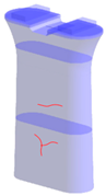 | 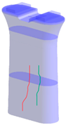 |  |  | 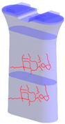 |
| Cases | 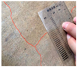 | 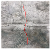 |  |  |  |
| Descriptions | Irregular cracks | Vertical cracks | Horizontal cracks | Arc segment cracking | Honeycomb cracks |
| Parameters | C35 | C45 |
|---|---|---|
| Final elastic modulus E∞ | 32 GPa | 36 GPa |
| Final tensile strength ft∞ | 2.3 MPa | 2.6 MPa |
| Poisson’s ratio | 0.23 | 0.23 |
| Pouring interval age | 7/15/30 d | 7/15/30 d |
| 7-day adiabatic temperature rise | 43 °C | 47 °C |
| 28-day shrink | 150 με | 200 με |
| Concrete | σt/MPa | Early Cracking | Long Term |
|---|---|---|---|
| C35 | 2.0 | 0.92 | 1.1 |
| 2.3 | 0.69 (↓33%) | 0.91 (↓21%) |
| Concrete | Adiabatic Temperature Rise/°C | Early Cracking | Long Term |
|---|---|---|---|
| C35 | 43 | 0.69 | 0.91 |
| 50 | 0.87 (↑26%) | 1 (↑10%) |
| Concrete | Pouring Interval Age/d | Early Cracking | Long Term |
|---|---|---|---|
| C35 | 7 | 0.69 | 0.91 |
| 14 | 0.93 (↑35%) | 1.15 (↑26%) | |
| 30 | 1.24 (↑79%) | 1.35 (↑48%) |
| Cement | Fly Ash | HΜΕ®-V | Sand | Aggregate | Water | |
|---|---|---|---|---|---|---|
| Pier 1# | 320 | 80 | 0 | 774 | 1070 | 150 |
| Pier 2# | 300 | 68 | 32 | 774 | 1070 | 150 |
| Concrete | σt/MPa | Early Cracking | Long Term |
|---|---|---|---|
| C35-HME | 2.0 | 0.73 | 0.92 |
| 2.3 | 0.56 (↓30%) | 0.77 (19%) |
| Concrete | Adiabatic Temperature Rise/°C | Early Cracking | Long Term |
|---|---|---|---|
| C35-HME | 43 | 0.56 | 0.77 |
| 50 | 0.72 (↑28%) | 0.88 (↑14%) |
| Concrete | Pouring Interval Age/d | Early Cracking | Long Term |
|---|---|---|---|
| C35-HME | 7 | 0.56 | 0.77 |
| 14 | 0.77 (↑37%) | 1.0 (↑30%) | |
| 30 | 1.11(↑98%) | 1.25(↑62%) |
| No. | Strategy | Stands |
|---|---|---|
| 1 | Water | Low-temperature water prepared using groundwater or cold-water machine. |
| 2 | Cement | With 3 d hydration heat ≤ 230 kJ/kg, 7 d hydration heat ≤ 260 kJ/kg, C2S ≥ 40% and C3A ≤ 6% [28]. |
| 3 | Mixing time | The mixing time of each concrete mixer should not be less than 120 s. |
| 4 | Transportation | Concrete transport vehicles should have insulation or thermal insulation measures; the transportation time should not exceed 60 min. |
| 5 | Pumping | ① The concrete molding temperature falls within the range of 5–25 °C. ② The pumping temperature should be lowered, or construction should be conducted during low temperature seasons. This can also mitigate the risk of long-term concrete cracking. |
| 6 | Pouring and vibration | ① In cases where there is a substantial loss of slump that fails to meet the requirements, it can be rectified by adding a suitable amount of water-reducing agent twice, with direct water addition being strictly prohibited. ② Concrete should be poured continuously in layers, with each layer having a thickness of 30–50 cm. The time between layers should not exceed the initial setting time of the concrete. ③ The thickness of vibration pouring ranged from 30–50 cm, and the vibration time was determined based on the factors of concrete surface bleeding, absence of significant sinking and no appearance of bubbles. |
| 7 | Demolding and maintenance | ① Concrete formwork should be removed during periods of high temperatures. After the removal of concrete formwork, a water energy film should be applied and covered with a minimum of two layers of geotextiles with plastic lining. ② In conditions of strong winds, rainy days and sudden temperature drops, it was recommended to extend the demolding time to prevent cold cracking. ③ The cooling rate of concrete should be ≤2.0 °C/d, and the temperature difference between the inner and outer surfaces should be maintained at ≤ 20 °C. ④ When mold curing was adopted, it was recommended to embed insulation materials such as a rubber sponge and XPS board in the steel formwork, and to wrap windproof tarpaulin around the exterior of the formwork. Additionally, post-dismantling of the formwork, it was recommended to continue long-term insulation and moisturizing curing. ⑤ The temperature difference between the curing water and the concrete surface should be less than 15 °C. |
Disclaimer/Publisher’s Note: The statements, opinions and data contained in all publications are solely those of the individual author(s) and contributor(s) and not of MDPI and/or the editor(s). MDPI and/or the editor(s) disclaim responsibility for any injury to people or property resulting from any ideas, methods, instructions or products referred to in the content. |
© 2024 by the authors. Licensee MDPI, Basel, Switzerland. This article is an open access article distributed under the terms and conditions of the Creative Commons Attribution (CC BY) license (https://creativecommons.org/licenses/by/4.0/).
Share and Cite
Hu, X.; Liao, M.; Li, M.; Wang, F.; Lyu, X.; Zhuang, M.-L. Investigations on the Environmental Characteristics and Cracking Control of Plateau Concrete. Buildings 2024, 14, 2104. https://doi.org/10.3390/buildings14072104
Hu X, Liao M, Li M, Wang F, Lyu X, Zhuang M-L. Investigations on the Environmental Characteristics and Cracking Control of Plateau Concrete. Buildings. 2024; 14(7):2104. https://doi.org/10.3390/buildings14072104
Chicago/Turabian StyleHu, Xiaochuan, Manping Liao, Ming Li, Fuqiang Wang, Xiang Lyu, and Mei-Ling Zhuang. 2024. "Investigations on the Environmental Characteristics and Cracking Control of Plateau Concrete" Buildings 14, no. 7: 2104. https://doi.org/10.3390/buildings14072104