
Bonding Performance and Microstructural Mechanism between Rapid Repair Materials and Old Concrete Pavement

Abstract
:1. Introduction
2. Materials and Methods
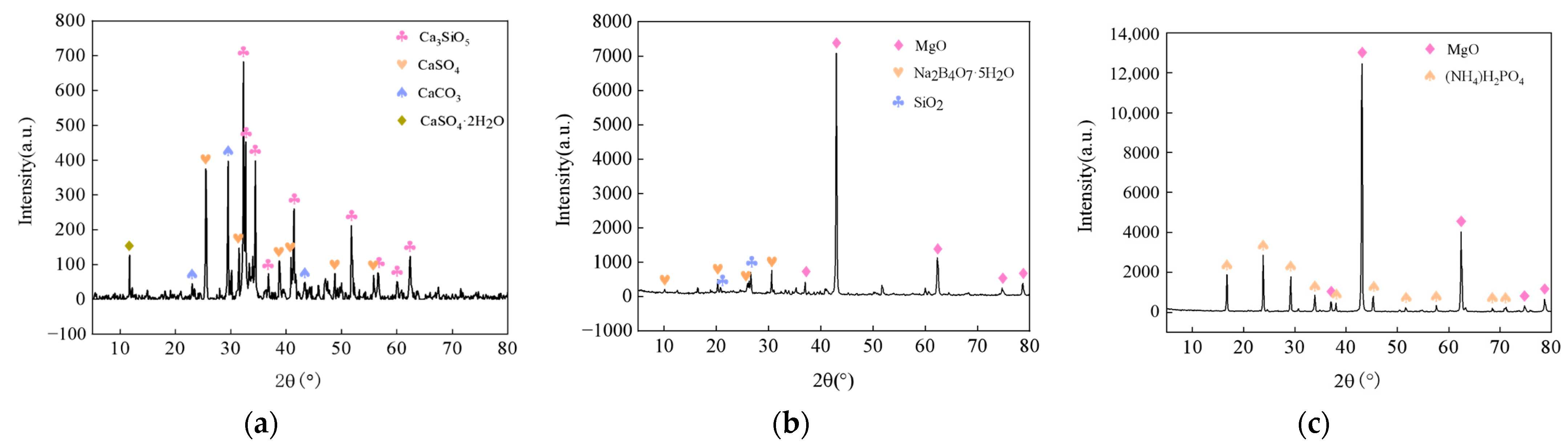
2.1. Materials
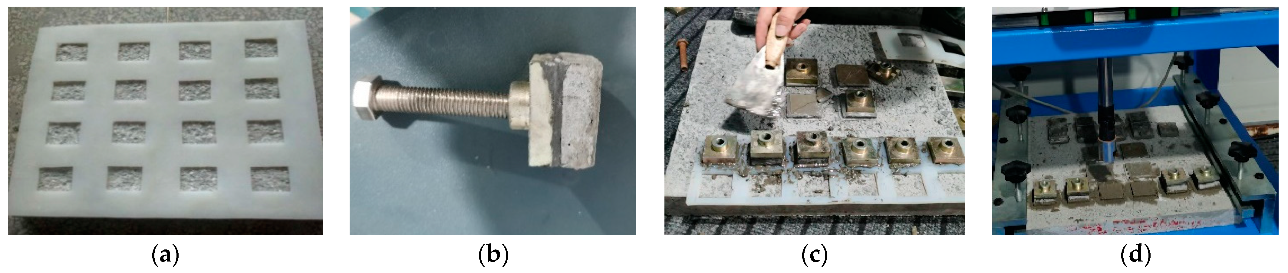
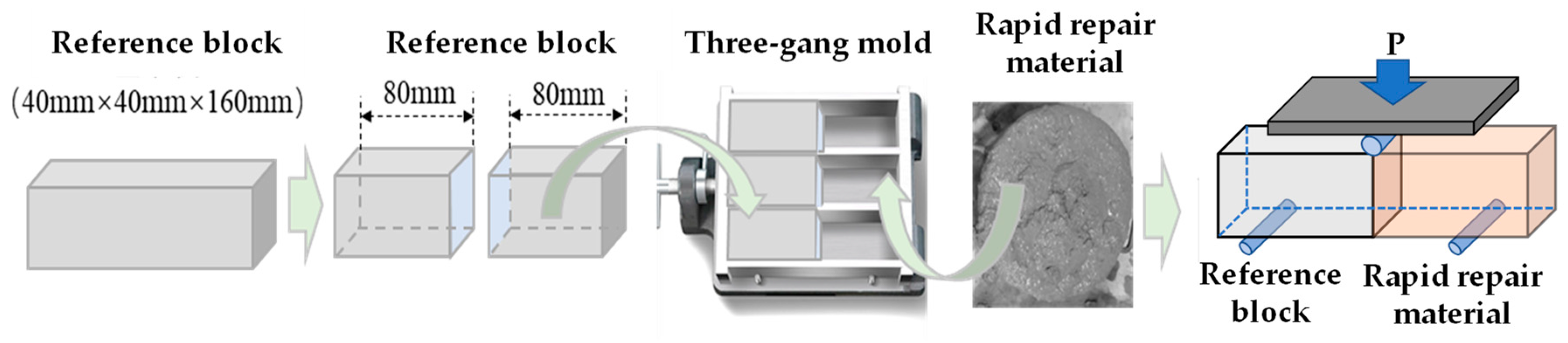
2.2. Test Methods
2.2.1. Pull-Out Test
2.2.2. Interfacial Flexural Test
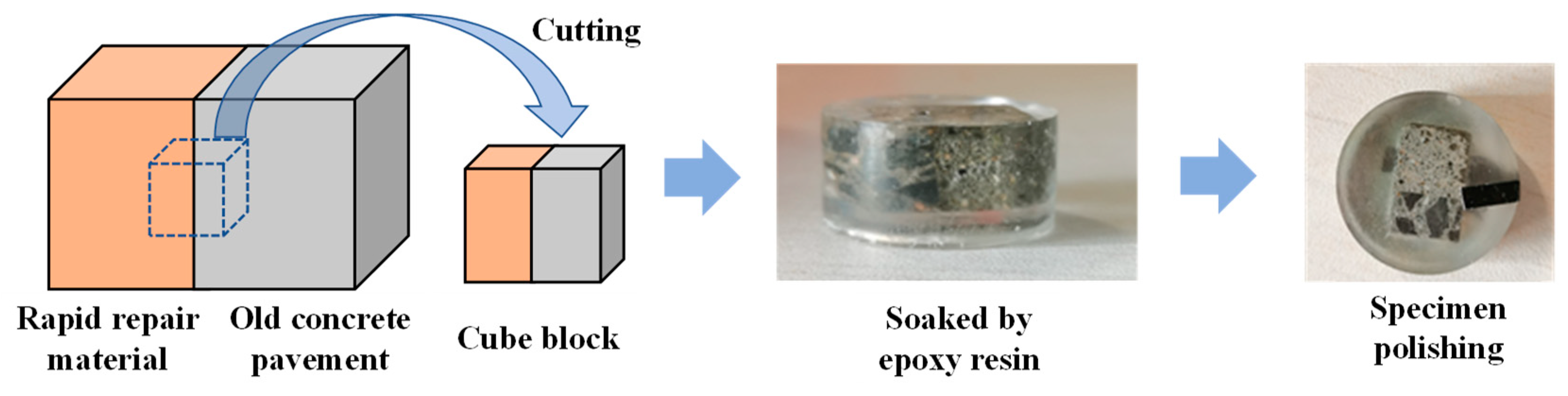
2.2.3. SEM and EDS
3. Results and Discussion
3.1. Interfacial Bonding Strength
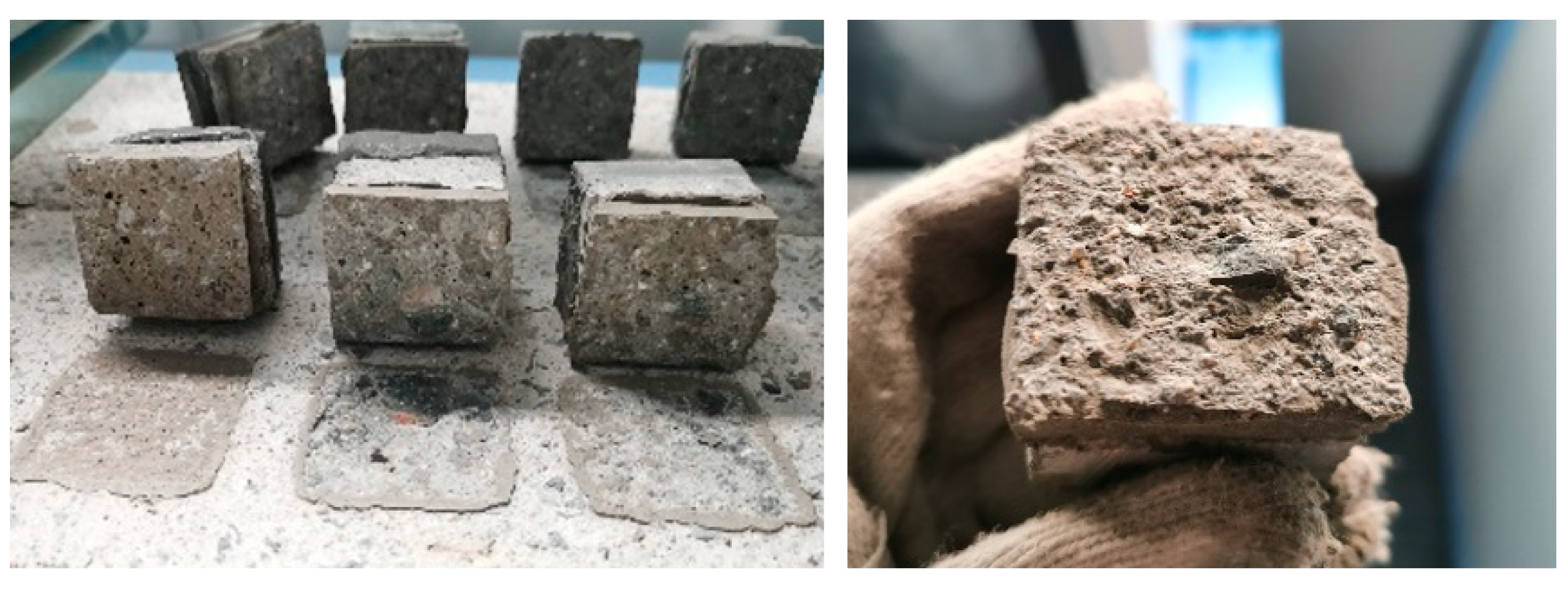
3.1.1. Failure Modes
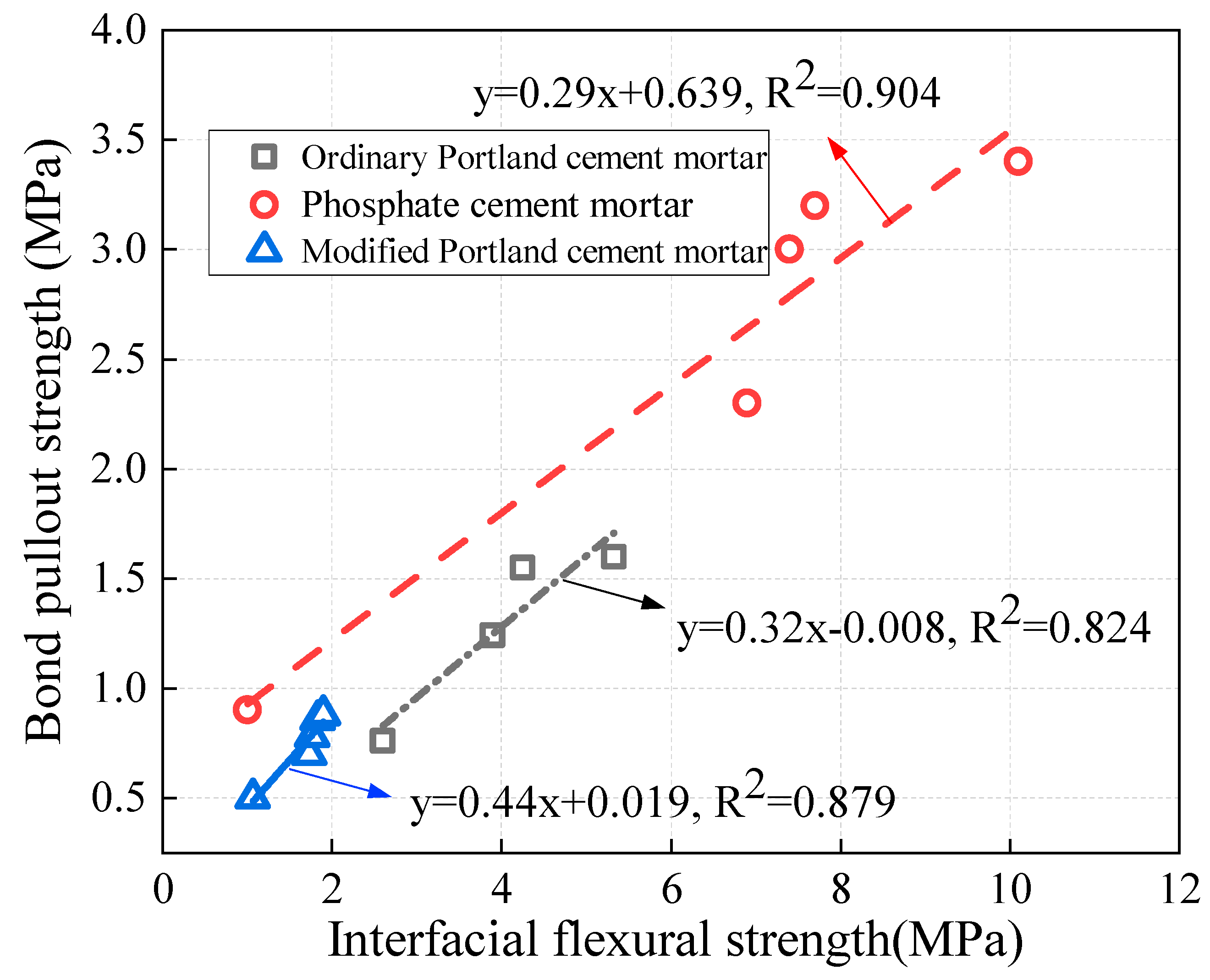
3.1.2. Bonding Strength
3.2. Microstructural Analysis
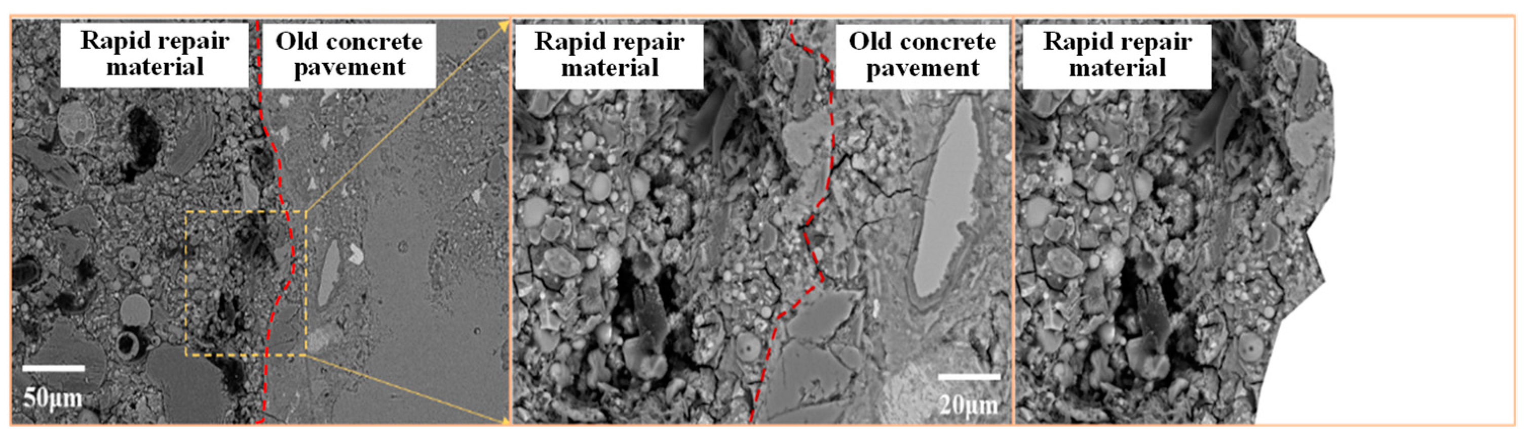
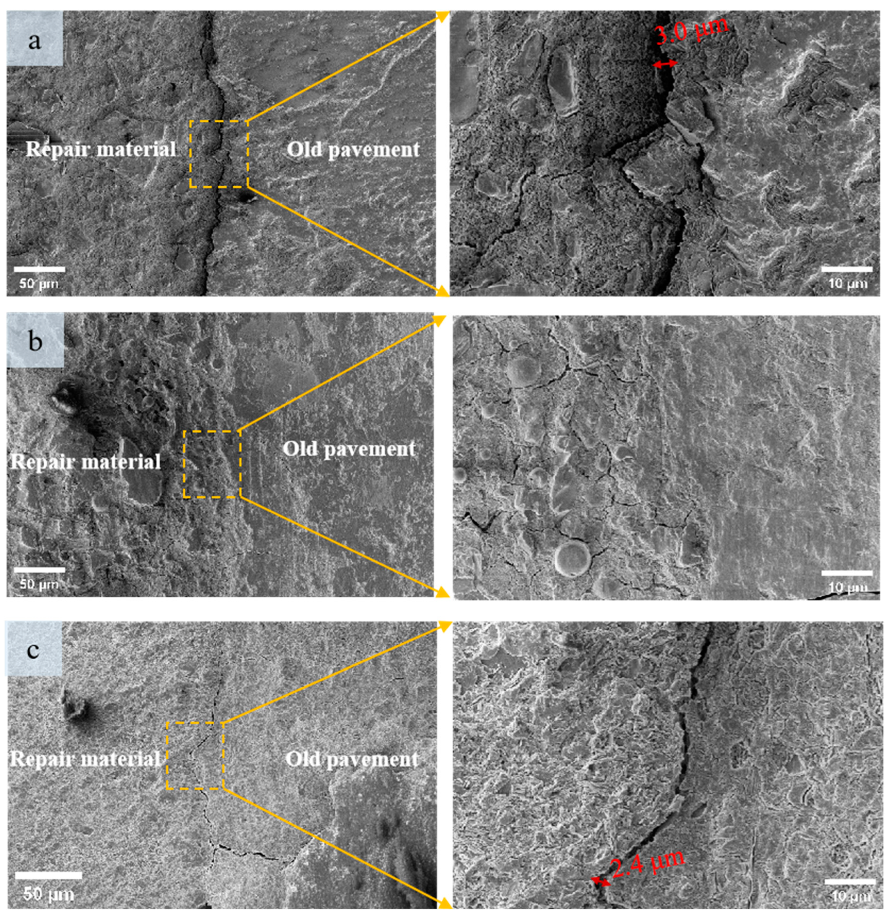
3.2.1. Microtopography
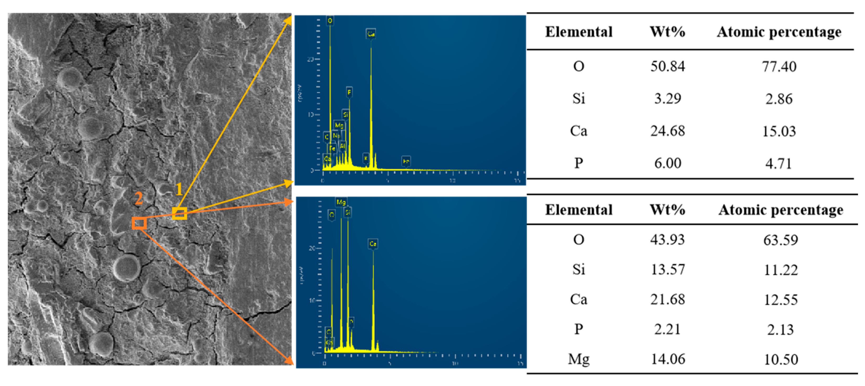
3.2.2. Element Distribution
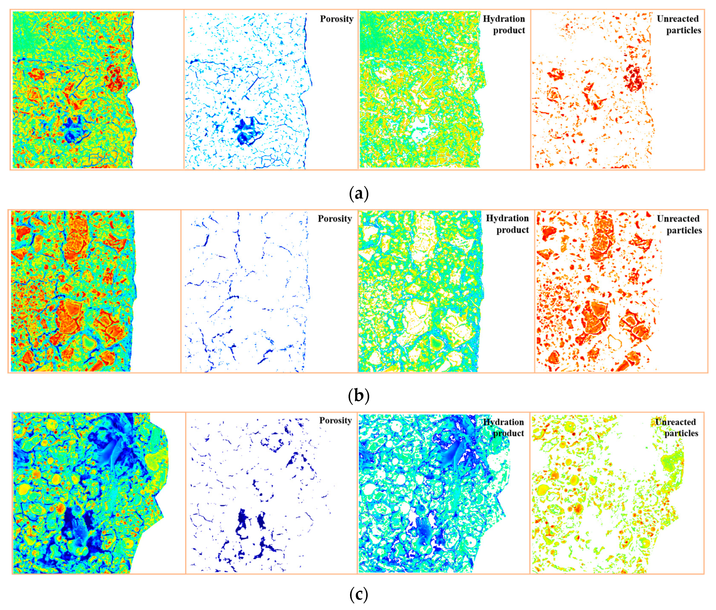
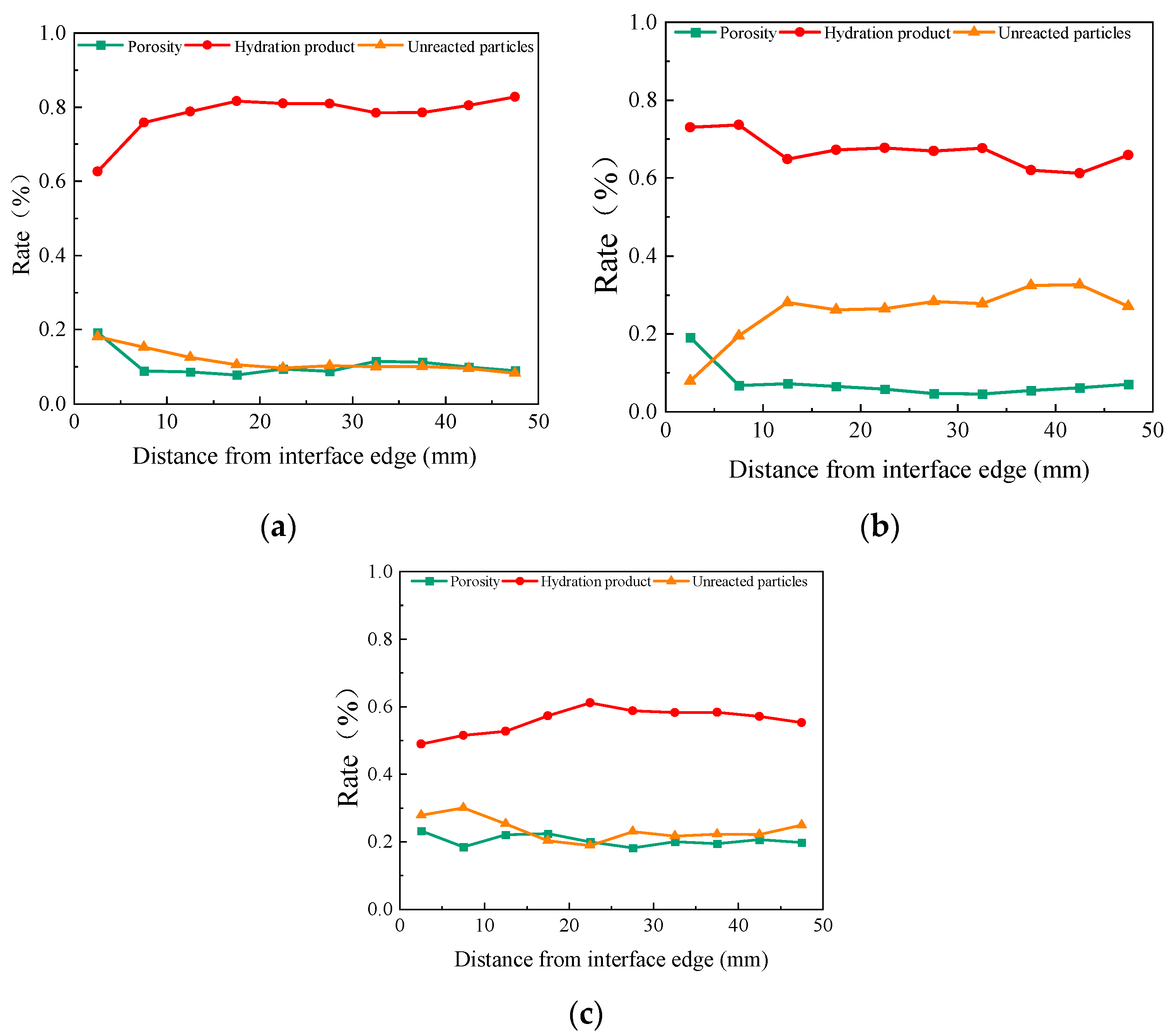
3.2.3. Phase Distribution
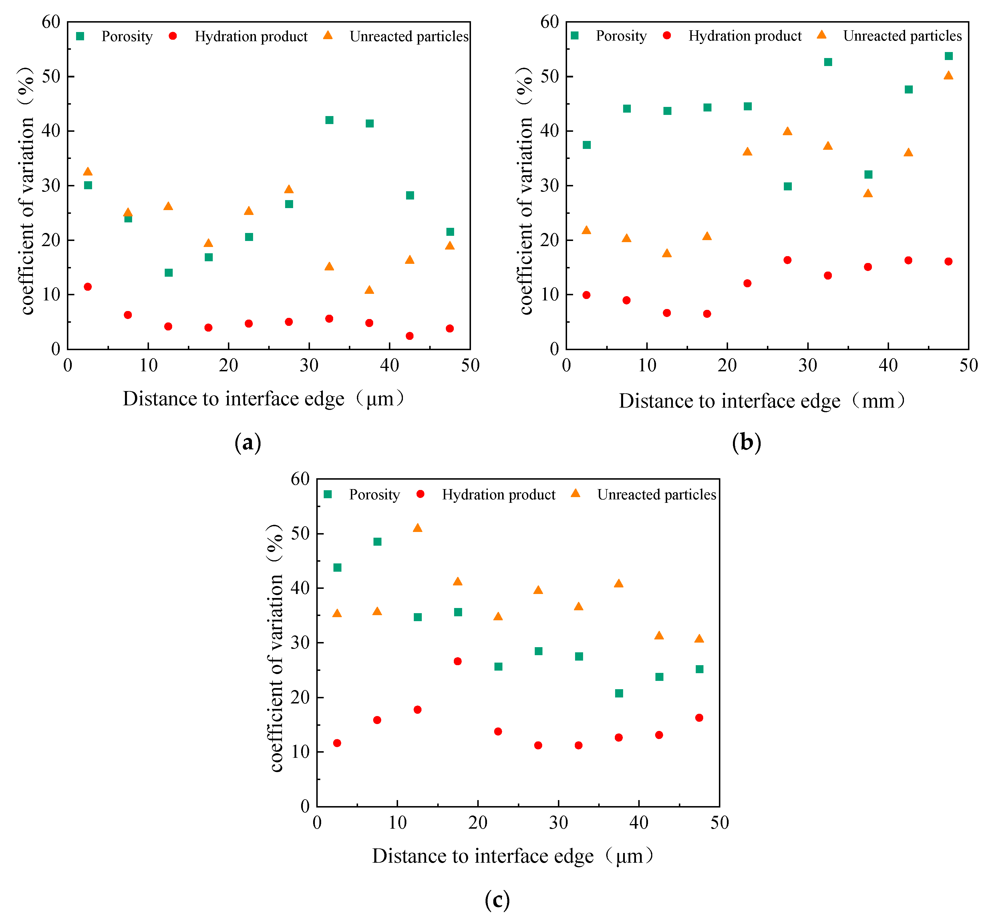
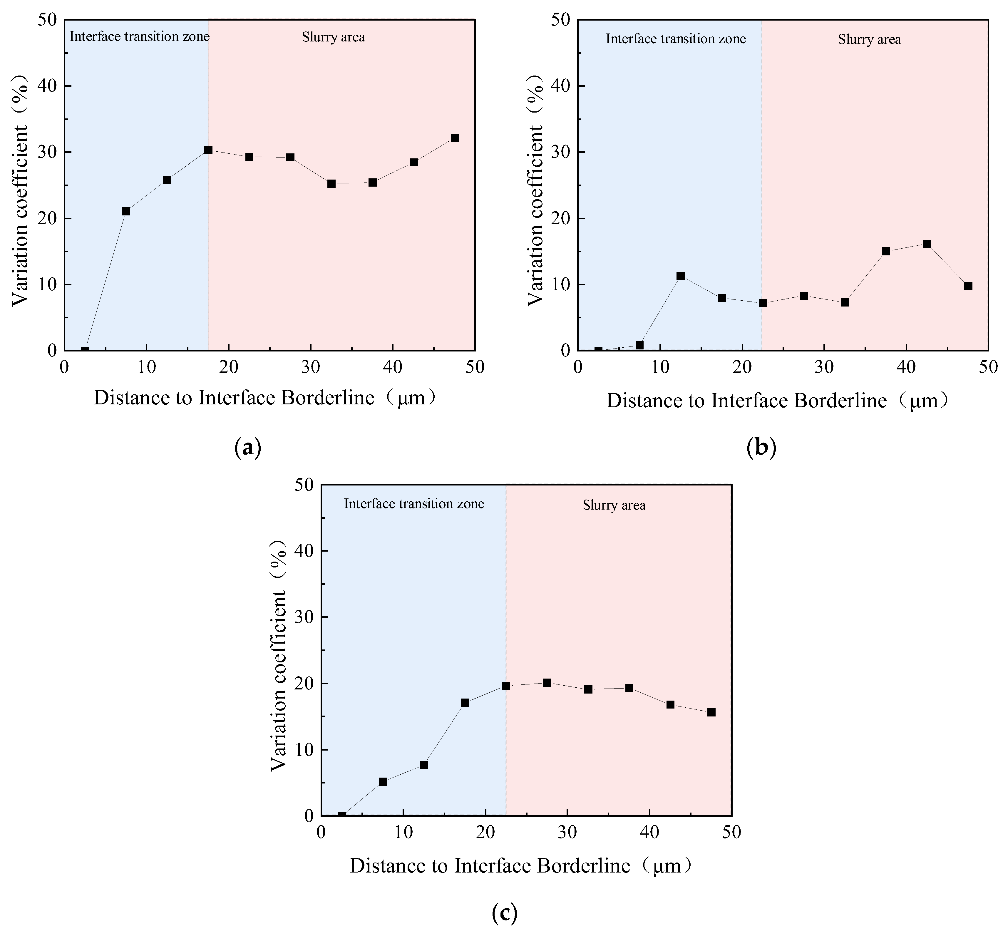
3.2.4. Thickness of the ITZ
3.3. Interfacial Bonding Mechanisms
- (1)
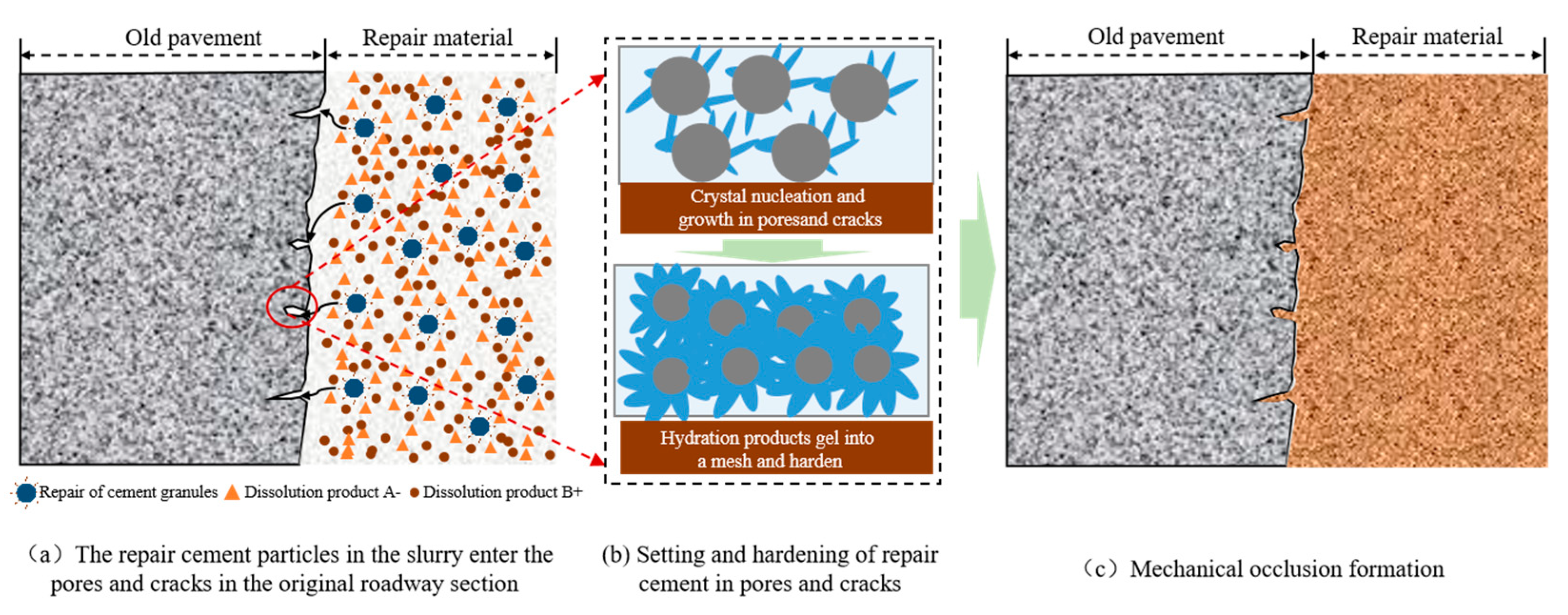
- The process of forming a rapid repair cement material involves pouring the cement particles into the pores and cracks on the original roadway section, followed by a hydration reaction where the hydration products progressively become more hydrated. The original airport pavement surfaces are then riveted to each other, creating a mechanical occlusion effect, as shown in Figure 19. Interface bond strength and material body strength correlation analysis shows that this role is influenced by the repair material hydration product strength, which increases macro-performance as material body strength develops. The primary cause of early interfacial bond strength at the repair interface is mechanical occlusion, which has varying effects depending on the material’s early-strength development rate, the hydration product characteristics, and degree of interfacial defect filling in the original course surface;
- (2)
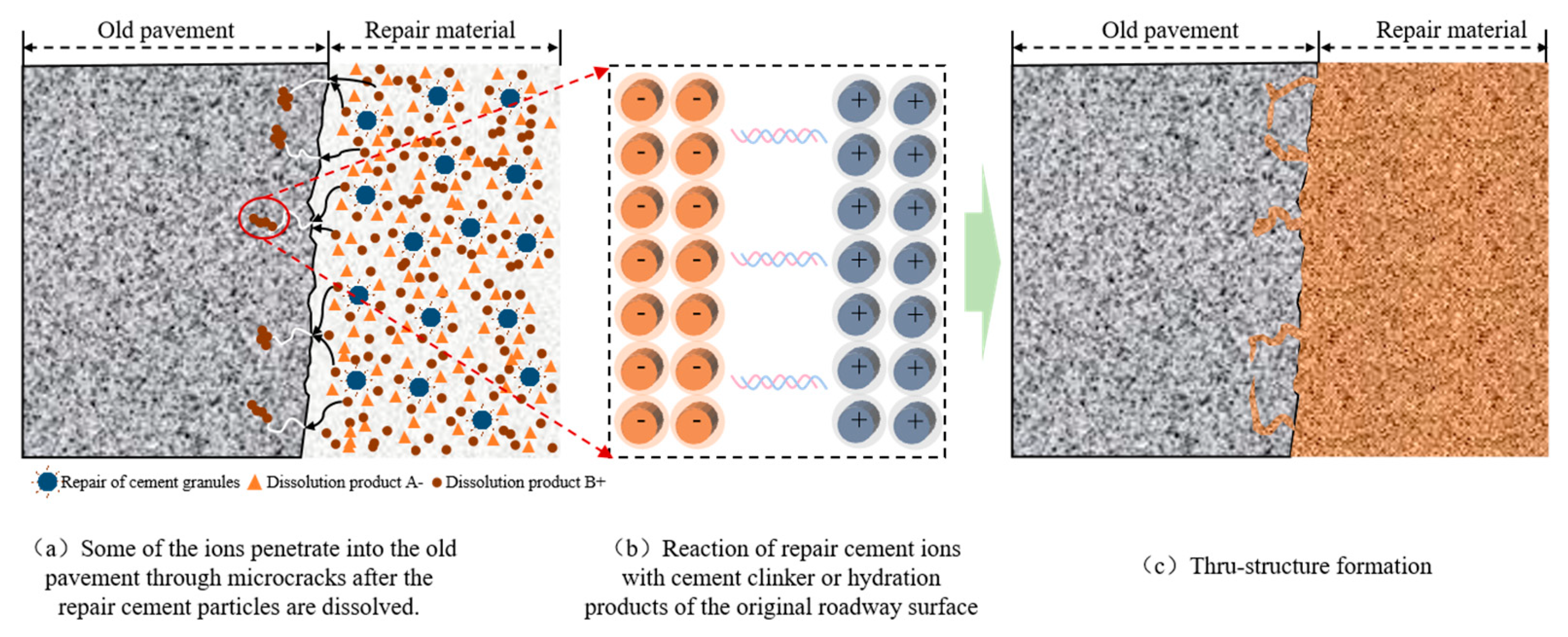
- Some of the dissolved ions penetrate into the original pavement through the microcracks under the effect of adsorption and have a series of chemical reactions with unreacted cement clinker or hydration products to generate new products, and through the hydration products in the microcracks, the repair material and the original pavement are bonded together, forming a structure that penetrates through the original pavement of cement stones and aggregates, as shown in Figure 20. This sort of structure considerably improves the interfacial bonding qualities, and pulling out of the original pavement components happens during strength testing. However, its production is tied to the qualities of the repair material, and in combination with the microstructure of the interface and the type of damage to the bonded specimens, this structural form is obvious at the interface between the phosphate cement mortar and the original pavement;
- (3)
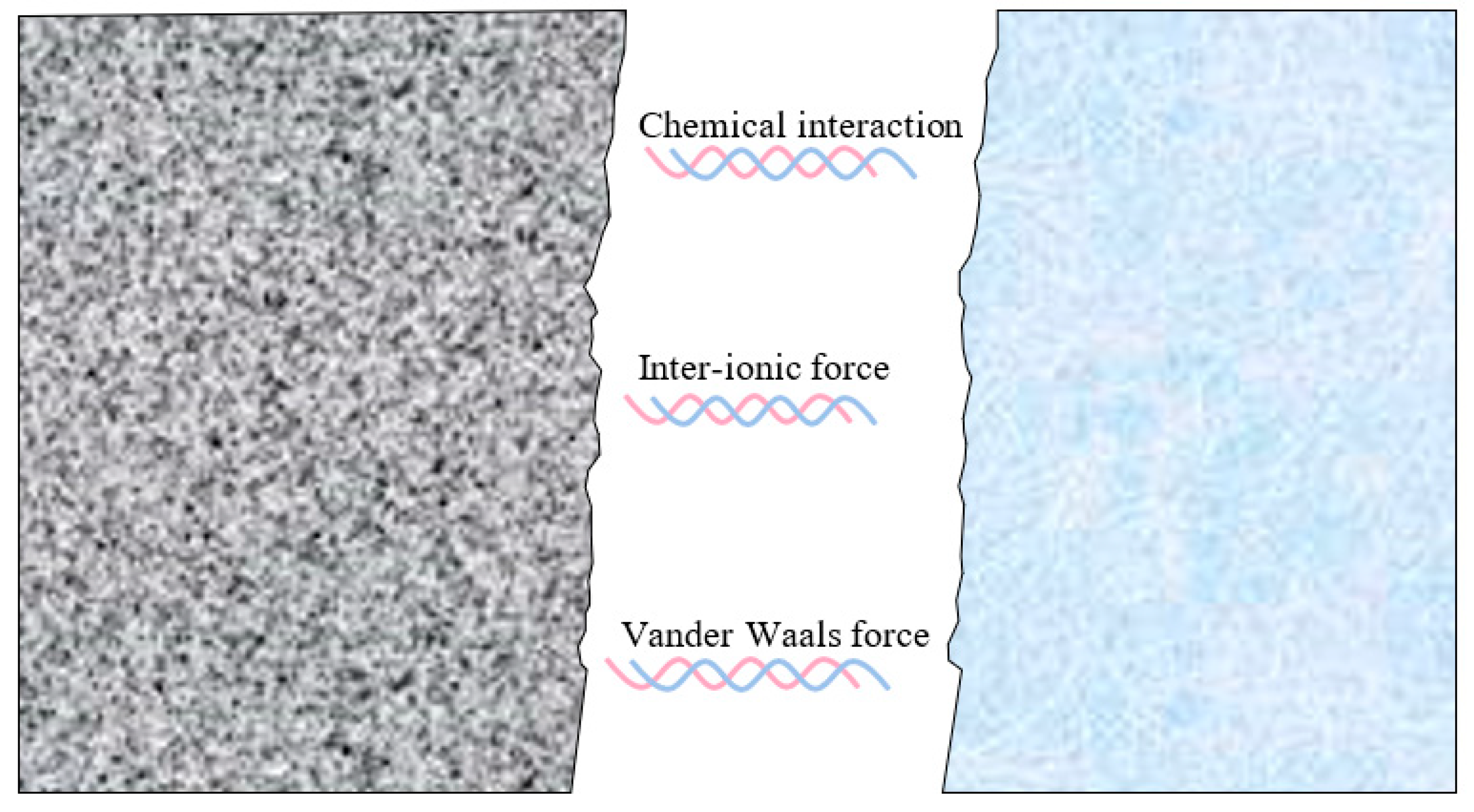
- The unreacted particles and hydration products of the original airport pavement surface will be partially dissolved in the repair material’s solution at the interface between the old and new pavement surfaces. The ions of the old and new materials will be drawn to one another, creating intermolecular forces, or van der Waals forces, while some of the ions will simultaneously react to form chemical bonds, as shown in Figure 21. Both of these processes make a substantial contribution to the interfacial bonding qualities, with van der Waals forces present at most repaired cement interfaces, while the creation of chemical bonding is dependent on the chemical composition of the repair material;
- (4)
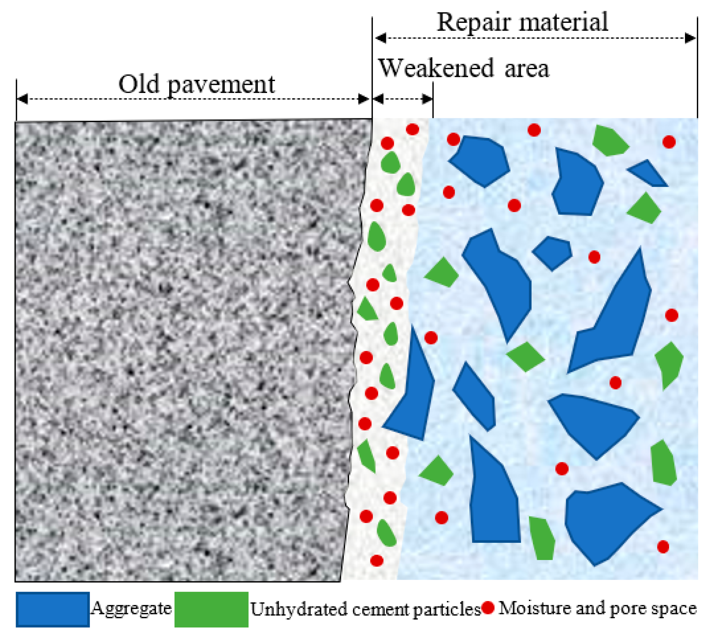
- Due to the sidewall effect, the repair material’s side interface area has a low degree of cement hydration, creating a loose and porous performance-weakening area as shown in Figure 22. Based on prior experiments and data analysis, it was discovered that the performance of various repair cement materials in the weakened region had similar thicknesses. This suggests that the influence of the original airport pavement surface on the repair material’s performance is not very different. However, the fraction of microscopic phases in this area is varied, and its influence on the total interfacial bonding performance needs to be evaluated in connection with other aspects.
3.4. Discussion
4. Conclusions
- (1)
- The interface bonding strength between phosphate cement mortar and old concrete pavement is higher than that of Portland cement mortar and modified Portland cement mortar;
- (2)
- The elements in phosphate cement permeate into the old concrete pavement through hydration reactions, forming van der Waals forces and chemical bonding forces. The interfacial adhesion of Portland cement mortar and modified Portland cement mortar mainly comes from van der Waals forces and mechanical interlocking, with weak chemical bonding at the interface;
- (3)
- The presence of the old concrete pavement will generate a sidewall effect, resulting in a lower hydration degree of the repair material and the formation of a porous structure at the interface. Compared to ordinary Portland cement mortar, modified Portland cement mortar had the lowest degree of interfacial hydration with 26.55% of unhydrated cement particles. The hydration degree of phosphate cement at the interface is relatively low, but its interface bonding strength is the highest, making the overall interface bonding performance optimal;
- (4)
- Compared to the adsorption of van der Waals forces and mechanical bite effects, chemical bonding and the formation of a penetrating structure on the old concrete pavement have a greater improvement effect on interface bonding performance, which can compensate for the weakening effect of the repair material in the ITZ to some extent.
Author Contributions
Funding
Data Availability Statement
Conflicts of Interest
References
- White, G. State of the art: Asphalt for airport pavement surfacing. Int. J. Pavement Res. Technol. 2018, 11, 77–98. [Google Scholar] [CrossRef]
- Lu, H.; Zhao, C.; Yuan, J.; Yin, W.; Wang, Y.; Xiao, R. Study on the Properties and Benefits of a Composite Separator Layer in Airport Cement Concrete Pavement. Buildings 2022, 12, 2190. [Google Scholar] [CrossRef]
- Zhang, J.; Zhang, G.; Wang, Y.; Yuan, J. Mechanical behavior of doweled joints in concrete pavements: A review. J. Transp. Eng. Part B Pavements 2022, 148, 03122002. [Google Scholar] [CrossRef]
- Babashamsi, P.; Khahro, S.H.; Omar, H.A.; Al-Sabaeei, A.M.; Memon, A.M.; Milad, A.; Khan, M.I.; Sutanto, M.H.; Yusoff, N.I.M. Perspective of life-cycle cost analysis and risk assessment for airport pavement in delaying preventive maintenance. Sustainability 2022, 14, 2905. [Google Scholar] [CrossRef]
- Wang, H. Life-cycle analysis of repair of concrete pavements. Eco-Effic. Repair Rehabil. Concr. Infrastruct. 2018, 723–738. [Google Scholar] [CrossRef]
- Song, X.; Song, X.; Liu, H.; Huang, H.; Anvarovna, K.G.; Ugli, N.A.D.; Huang, Y.; Hu, J.; Wei, J.; Yu, Q. Cement-based repair materials and the interface with concrete substrates: Characterization, evaluation and improvement. Polymers 2022, 14, 1485. [Google Scholar] [CrossRef]
- Allahvirdizadeh, R.; Rashetnia, R.; Dousti, A.; Shekarchi, M. Application of polymer concrete in repair of concrete structures: A literature review. In Concrete Solutions, 1st ed.; Grantham, M., Mechtcherine, V., Schneck, U., Eds.; CRC Press: London, UK, 2011; pp. 435–444. [Google Scholar] [CrossRef]
- Soupionis, G.; Georgiou, P.; Zoumpoulakis, L. Polymer composite materials fiber-reinforced for the reinforcement/repair of concrete structures. Polymers 2020, 12, 2058. [Google Scholar] [CrossRef] [PubMed]
- Huseien, G.F.; Mirza, J.; Ismail, M.; Ghoshal, S.K.; Hussein, A.A. Geopolymer mortars as sustainable repair material: A comprehensive review. Renew. Sustain. Energy Rev. 2017, 80, 54–74. [Google Scholar] [CrossRef]
- Rudnicki, T.; Stałowski, P. Fast-Setting Concrete for Repairing Cement Concrete Pavement. Materials 2023, 16, 5909. [Google Scholar] [CrossRef]
- Li, G.; Bai, Z.; Zhang, G.; Wu, Y. Study on properties and degradation mechanism of calcium sulphoaluminate cement-ordinary Portland cement binary repair material under seawater erosion. Case Stud. Constr. Mater. 2022, 17, e01440. [Google Scholar] [CrossRef]
- Ma, J.; Wang, H.; Yu, Z.; Shi, H.; Wu, Q.; Shen, X. A systematic review on durability of calcium sulphoaluminate cement-based materials in chloride environment. J. Sustain. Cem. Based Mater. 2023, 12, 687–698. [Google Scholar] [CrossRef]
- Gholami, S.; Hu, J.; Kim, Y.R. Assessment of bonding, durability, and low-temperature performance of cement-based rapid patching materials for pavement repair. Int. J. Pavement Eng. 2023, 24, 2120990. [Google Scholar] [CrossRef]
- Xiao, Z.; Guo, J. Discussion on reduction mechanism of flexural strength of quick hardening sulpho-aluminate cement. Cement 2016, 12, 3–5. [Google Scholar]
- Tao, Y.; Rahul, A.V.; Mohan, M.K.; Schuttera, G.D.; Tittelboom, K.V. Recent progress and technical challenges in using calcium sulfoaluminate (CSA) cement. Cem. Concr. Compos. 2023, 137, 104908. [Google Scholar] [CrossRef]
- Yang, Q.; Zhu, B.; Zhang, S.; Wu, X. Properties and applications of magnesia–phosphate cement mortar for rapid repair of concrete. Cem. Concr. Res. 2000, 30, 1807–1813. [Google Scholar] [CrossRef]
- Yang, Q.; Zhang, S.; Wu, X. Deicer-scaling resistance of phosphate cement-based binder for rapid repair of concrete. Cem. Concr. Res. 2002, 32, 165–168. [Google Scholar] [CrossRef]
- Wang, H.; Xue, M.; Cao, J. Research on the durability of magnesium phosphate cement. Adv. Mater. Res. 2011, 168, 1864–1868. [Google Scholar] [CrossRef]
- Hall, D.A.; Stevens, R.; El-Jazairi, B. The effect of retarders on the microstructure and mechanical properties of magnesia-phosphate cement mortar. Cem. Concr. Res. 2001, 31, 455–465. [Google Scholar] [CrossRef]
- Baloch, W.L.; Siad, H.; Lachemi, M.; Sahmaran, M. A review on the durability of concrete-to-concrete bond in recent rehabilitated structures. J. Build. Eng. 2021, 44, 103315. [Google Scholar] [CrossRef]
- Zhang, Y.; Zhu, P.; Liao, Z.; Wang, L. Interfacial bond properties between normal strength concrete substrate and ultra-high-performance concrete as a repair material. Constr. Build. Mater. 2020, 235, 117431. [Google Scholar] [CrossRef]
- Rashid, K.; Ahmad, M.; Ueda, T.; Deng, J.; Aslam, K.; Nazir, I.; Sarwar, M.A. Experimental investigation of the bond strength between new to old concrete using different adhesive layers. Constr. Build. Mater. 2020, 249, 118798. [Google Scholar] [CrossRef]
- Formosa, J.; Lacasta, A.M.; Navarro, A.; del Valle-Zermeño, R.; Niubó, M.; Rosell, J.R.; Chimenos, J.M. Magnesium phosphate cements formulated with a low-grade MgO by-product: Physico-mechanical and durability aspects. Constr. Build. Mater. 2015, 91, 150–157. [Google Scholar] [CrossRef]
- Qin, J.; Qian, J.; You, C.; Fan, Y.; Li, Z.; Wang, H. Bond behavior and interfacial micro-characteristics of magnesium phosphate cement onto old concrete substrate. Constr. Build. Mater. 2018, 167, 166–176. [Google Scholar] [CrossRef]
- Lyu, K.; She, W.; Chang, H.; Gu, Y. Effect of fine aggregate size on the overlapping of interfacial transition zone (ITZ) in mortars. Constr. Build. Mater. 2020, 248, 118559. [Google Scholar] [CrossRef]
- Qian, J.; You, C.; Wang, Q.; Wang, H.; Jia, X. A method for assessing bond performance of cement-based repair materials. Constr. Build. Mater. 2014, 68, 307–313. [Google Scholar] [CrossRef]
- Xu, B.; Ma, H.; Shao, H.; Li, Z.; Lothenbach, B. Influence of fly ash on compressive strength and micro-characteristics of magnesium potassium phosphate cement mortars. Cem. Concr. Res. 2017, 99, 86–94. [Google Scholar] [CrossRef]
- Agyei, N.M.; Strydom, C.A.; Potgieter, J.H. The removal of phosphate ions from aqueous solution by fly ash, slag, ordinary Portland cement and related blends. Cem. Concr. Res. 2002, 32, 1889–1897. [Google Scholar] [CrossRef]
- Ma, H.; Li, Z. Multi-aggregate approach for modeling interfacial transition zone in concrete. ACI Mater. J. 2014, 111, 189. [Google Scholar] [CrossRef]
- Diamond, S. Considerations in image analysis as applied to investigations of the ITZ in concrete. Cem. Concr. Compos. 2001, 23, 171–178. [Google Scholar] [CrossRef]
- Fang, G.; Zhang, M. The evolution of interfacial transition zone in alkali-activated fly ash-slag concrete. Cem. Concr. Res. 2020, 129, 105963. [Google Scholar] [CrossRef]


| Fineness (0.08/%) | Specific Surface Area (m2/kg) | Setting Time (min) | Compressive Strength (MPa) | Flexural Strength (MPa) | |||
|---|---|---|---|---|---|---|---|
| Initial | Final | 3 d | 28 d | 3 d | 28 d | ||
| 0.2 | 349.4 | 126 | 166 | 32.6 | 60.6 | 6.3 | 8.8 |
| Repair Material Type | Ordinary Portland Cement Mortar | Modified Portland Cement Mortar | Portland Cement Mortar |
|---|---|---|---|
| ITZ thickness | 20 μm | 25 μm | 25 μm |
Disclaimer/Publisher’s Note: The statements, opinions and data contained in all publications are solely those of the individual author(s) and contributor(s) and not of MDPI and/or the editor(s). MDPI and/or the editor(s) disclaim responsibility for any injury to people or property resulting from any ideas, methods, instructions or products referred to in the content. |
© 2024 by the authors. Licensee MDPI, Basel, Switzerland. This article is an open access article distributed under the terms and conditions of the Creative Commons Attribution (CC BY) license (https://creativecommons.org/licenses/by/4.0/).
Share and Cite
Bao, K.; Zhang, G.; Lv, J.; Li, J.; Chen, Z.; Yuan, J. Bonding Performance and Microstructural Mechanism between Rapid Repair Materials and Old Concrete Pavement. Buildings 2024, 14, 2156. https://doi.org/10.3390/buildings14072156
Bao K, Zhang G, Lv J, Li J, Chen Z, Yuan J. Bonding Performance and Microstructural Mechanism between Rapid Repair Materials and Old Concrete Pavement. Buildings. 2024; 14(7):2156. https://doi.org/10.3390/buildings14072156
Chicago/Turabian StyleBao, Kan, Gaowang Zhang, Jiangpeng Lv, Junmin Li, Zexin Chen, and Jie Yuan. 2024. "Bonding Performance and Microstructural Mechanism between Rapid Repair Materials and Old Concrete Pavement" Buildings 14, no. 7: 2156. https://doi.org/10.3390/buildings14072156