Article

Study of the Dynamic Reaction Mechanism of the Cable-Stayed Tube Bridge under Earthquake Action

1
School of Civil Engineering, Xi’an Shiyou University, Xi’an 710065, China
2
School of Mechanical Engineering, Xi’an Shiyou University, Xi’an 710065, China
*
Author to whom correspondence should be addressed.
Buildings 2024, 14(7), 2209; https://doi.org/10.3390/buildings14072209
Submission received: 14 June 2024 / Revised: 12 July 2024 / Accepted: 16 July 2024 / Published: 17 July 2024
(This article belongs to the Special Issue Structural Vibration Control Research)

Abstract

:
In order to explore the failure mode of the cable-stayed pipe bridge under earthquake action, taking the structural system of an oil and gas pipeline–cable-stayed pipe bridge as the research object, the full-scale finite element calculation model of the cable-stayed pipe bridge–oil and gas pipeline structural system as well as the finite element calculation model considering the additional mass of the oil and gas medium and the fluid–structure interaction effect were established by using ANSYS Workbench finite element software. The stress and displacement of the cable under the earthquake action were analyzed in the time history, as were the response characteristics of the cable when subjected to both methods. The calculation results show that the overall failure of the pipeline is basically the same under the two methods. Compared with the additional mass method, the solution for the fluid–structure coupling method can be derived through a comprehensive analysis of the flow field and structure, respectively, avoiding the sudden change caused by model simplification or calculation error so that the analysis results can better simulate the actual situation. In summary, the fluid–structure interaction method enables a more precise prediction of the dynamic response of the structure, and the findings of this research can provide a theoretical foundation and technical guidance for optimizing the seismic performance of cable-stayed pipe bridges.

1. Introduction

Due to the fact that the transverse stiffness of the cable-stayed bridge structure is much lower than the longitudinal stiffness, it is very sensitive to external forces. As the core force element of this structure, the stress state of the cable-stayed cable is very important to the overall stability. In recent years, researchers have effectively controlled the vibration of the cable by adjusting the static tension in the cable or by using Mr Dampers and the control system integrated with Arduino [1,2]. With the rapid escalation of China’s energy demand, UHVDC projects and natural gas pipeline construction have witnessed a significant increase, and resolving the technical challenges such as corrosion and potential damage caused by UHVDC grounding current to natural gas pipelines has become the key; meanwhile, the seismic performance of natural gas pipelines should not be overlooked, and equal attention should be paid to it [3]. Traditional seismic design typically focuses more on the inherent properties of the structure and its response to earthquake excitation. In accordance with the seismic technical code for oil and gas transmission pipeline engineering, the additional mass of non-structural components and media has a considerable impact on the natural vibration period and mode of the span structure with prominent geometric nonlinear effects, such as suspension cables and stay cables. To more reasonably reflect the seismic characteristics of the structure, the role of the additional mass needs to be taken into account. However, the vibration effect of the coupling between the medium and the pipe has not been considered in the specification. In structures like cable-stayed pipe bridges, the fluid movement interacts with the structural vibration, giving rise to complex coupling effects. This interaction can be captured by the fluid–solid coupling approach, thereby enabling more accurate prediction of the structure’s response under dynamic loads like earthquakes. Consequently, the significance of this method cannot be overlooked. In the monitoring of the cable, some existing means make it difficult to determine the change in cable force, but a small change in cable force may lead to the accumulation of fatigue and damage to the cable, which, once improperly affected, may cause irreversible damage to the overall structure, which poses a threat to the long-term structural integrity and safety. Therefore, this study takes the cable-stayed cable of a petroleum and natural gas pipeline as the research object and investigates the influence of fluid–structure interaction-induced vibration while establishing the finite element calculation model. The failure mechanism of the oil and gas pipeline, which spans multiple points during intense seismic activity and is characterized by nonlinear behavior, is analyzed by setting the pipeline material nonlinearity, the coupling model of the medium in the pipeline, and the action parameters of rare earthquakes. Based on this premise, the time-history response of cable stress and displacement under earthquake action is analyzed, and the dynamic response characteristics of the cable under these two methods and their interaction with the whole structure of the cable-stayed pipe bridge are revealed.
Cable-stayed bridges are appealing and popular due to their reasonable force, convenient and safe construction as well as significant strength. However, cable-stayed bridges have low damping, complex dynamic characteristics, and high requirements for wind and seismic performance. When the span increases, the structural flexibility and the length of the cable-stayed bridge also increase, which may cause aerodynamic stability problems. Due to the diverse categories of dynamic loads, they are constantly exposed to varying degrees of vibration, which may lead to fatigue and fracture issues in the cable in the long run and may ultimately affect the safety of the cable-stayed bridge [4,5]. In view of the above problems, domestic and foreign scholars have conducted some studies on the dynamic reaction mechanism of the cable in the cable-stayed pipe bridge structure. Soltane, S. et al. [6] parameterized the dimensions of the damper in terms of its cross-sectional area and length by controlling the vibration mode of the cable by optimizing the parameters of the SMA damper attached transversally to the cable-stayed cable. D’Auteuil, A. et al. [7] used a dynamic test bench (NRC) equipped with large rain–wind-induced vibration (RWIV) to evaluate the vibration characteristics of smooth cable-stayed cables in two aspects: two cable inclination angles and different yaw angles. Wang, X. et al. [8] used the ANSYS Workbench finite element simulation method to analyze the change in wind speed and surface force distribution around the diagonal cable considering the fluid–structure interaction effect, simulated the force response of the sensor of the diagonal cable under different wind speeds, and the detection accuracy reached 96.17%. Tang, H. et al. [9] investigated the seismic response of cable-stayed bridges considering the potential failure of one or multiple cables under seismic excitation and concluded that there is a significant interaction between seismic oscillation and cable loss. Wang, P. et al. [10] adopted the double-circuit iterative method and discretized each single cable-stayed cable based on the shape diagram of the cable-stayed bridge based on the MECS model, and obtained the lateral displacement response of the cable-stayed cable and the change in the axial force of the cable-stayed cable. In order to model each cable, Jiang Y. et al. [11] used nonlinear truss elements and the same number of elastic beam–column members with zero parallel cross-sectional areas to obtain the external and parametric vibrations generated by the cable-stayed cable. Hua, J. et al. [12] evaluated the aerodynamic damping of full-size cable vibration interacting with wind and rain using a method used in vortex-induced vibration modeling. Therefore, in order to better study the variation law of cable dynamic performance across pipeline structures under earthquake action, it is necessary to consider the interaction between petroleum and natural gas medium and pipeline in theoretical analysis and numerical simulation to analyze the earthquake failure mechanism of straddling petroleum and natural gas pipelines [13]. With the swift advancement of modern engineering technology, the stability of engineering structures and their dynamic responses in the face of external excitation have emerged as the research foci. Particularly under the influence of the complex and mutable natural environment, the stability assessment and induced vibration analysis of engineering structures are of exceptional significance. Huang, H. et al. [14] designed and tested 25 reinforced concrete columns of 250 × 250 mm. Taking into account various loading approaches, reinforcement methods, and pre-damage grades, they discovered that the reinforcement of high-performance iron laminates in combination with steel plates could effectively enhance the bearing capacity of the columns and proposed an improved restoring force model for reinforced concrete columns. This model can precisely mirror the load-deformation curve of the test. Zhang, J. et al. [15] investigated the effect of viscoelastic materials with distinct mechanical properties on reducing the impact force between adjacent reinforced concrete buildings of varying heights (floors 9 and 3) under soil–structure interaction via numerical simulation. It was found that VE material can conspicuously reduce the structural force, acceleration amplification, and interlayer drift, and the effectiveness of VE material is influenced by the soil type, the constitutive parameters of the VE material, and the gap size; in particular, the gap size is critical to avoid impact. Fluid–structure interaction (FSI) refers to the intricate interplay between fluid dynamics and structural mechanics, presenting a complex coupling problem involving multiple physical phenomena. Since the 1970s, international scholars have dedicated their efforts to investigating the vibration issue arising from fluid–structure interaction. Schumacher, T. et al. [16] determined the properties of damping by extracting and analyzing the dynamic response characteristics, which provided an effective numerical simulation method for the dynamic fluid–structure interaction problem. dos Santos, J.D.B. et al. [17] used an oscillator combination to construct a simplified model to describe the structure or flow and analyzed the fluid–structure interaction caused by the flow in the pipeline. Sangalli, L.A. et al. [18] used optimal control theory to study the impact caused by active control accessories on the structural response of the unsteady bridge cross-section model and modeled the flow turbulence with a zonal coupling scheme which was developed to facilitate fluid–structure interaction by employing the large eddy simulation method (LES). Lee, U. et al. [19] obtained a nonlinear model describing the fluid–structure interaction effect of the structure by focusing on the influence of gravity, pipe material damping, and viscous damping and ignoring the influence of Poisson coupling. Simandjuntak, S. et al. [20] studied the effect of integrated inherent residual stress (RS) on curved pipes, which came from manufacturing and in-service loads, and adopted the joint RS–fluid–structure interaction (FSI) finite element analysis method to study the influence of geometrical factors on the stress distribution of the bending pipe. The investigation of fluid–structure interactions in the seismic response of pipeline vibration has emerged as a relatively recent research focus in China. Zhu, X. et al. [21] developed a finite element model accounting for the fluid–structure coupling effect for an oil–gas cable-stayed bridge, and the impact of the medium within the pipeline was analyzed. The responses of the bridge, including deformation, stress, strain, and other key dynamic responses of the oil and gas pipeline to seismic waves in various directions, were evaluated. Chen, Z. et al. [22] established an analytical solution of the nuclear dynamic differential equation based on Hamilton’s principle, which was consistent with the findings derived from the finite element analysis of the lateral vibration caused by the fluid–structure interaction, verifying its effect on the lateral vibration of the nuclear power pipeline. Li, T. et al. [23] established the Riccati fluid–structure coupled transfer equation (FSIRTE) based on the Riccati transfer matrix method (RTMM), which improves the numerical robustness of the conventional fluid–structure coupled transfer matrix approach (FSITMM) currently under investigation. Liang, J. et al. [24] analyzed the seismic performance of the pipeline under the action of fluid–structure interaction by establishing the finite element modeling of the pipeline and found that the failure of the pipeline was closely related to the density and velocity of the medium in the pipeline with the change in parameters such as the medium in the pipeline. Feng, L. [25], based on the theory of fluid–structure coupling vibration, established a finite element model of the natural gas pipeline and performed modal analysis, harmonic response analysis, and bidirectional fluid–structure interaction vibration response analysis of the natural gas transmission pipeline. The results showed that the low-order mode of the pipeline determines the vibration characteristics of the pipeline’s structure. Jafari, M. et al. [26] extensively reviewed the diverse factors contributing to cable vibration induced by the wind on the basis of existing articles, and by capitalizing upon prior investigations encompassing wind tunnel experiments, computational fluid dynamics, field measurements, or analytical techniques, addressed how to better understand the aerodynamic and fluid–structure interaction of cables. Xie, P. et al. [27] adopted the large eddy simulation (LES) method modeled by Smagorinski–Lilly to simulate the three-dimensional turbulent field and studied the influence of upstream flow on the influence of cable on aerodynamic force and the interaction between fluid flow and cable oscillation. Zhang, P. et al. [28] calculated the natural frequency of the gas column in a double-elbow pipeline by using the transfer matrix method, analyzed the modal characteristics of the pipeline under the fluid–structure coupling condition, and obtained the vibration characteristics of the natural gas pipeline with different internal diameters and curvature radii of the elbow. Li, X. [29], based on the “classical water hammer theory”, took the interaction between solid and fluid into account and formed an improved axial four-equation model with the simplified fluid momentum equation, pipeline motion equation, and physical equation to prevent the pipeline from failing due to vibration. At present, the analysis of the earthquake failure mechanism of cable-stayed straddling petroleum and natural gas pipelines at home and abroad is not perfect, and the scope of this study is currently limited to finite element simulation analysis, necessitating further experimental research. Bakhshizadeh, A. et al. [30] utilized the ABAQUS software to investigate the dynamic response of cable-stayed bridges with long spans under seismic excitations, and compared with the same method, a more accurate energy index of the strain response method was obtained. Chen, Y. [31] combined the process of incremental dynamic analysis to study the seismic vulnerability of bridges, then conducted the research under multi-dimensional ground motion input, and compared it with the one-dimensional result, summarizing the influencing factors of traveling wave effect on the susceptibility of bridges to seismic activity. Xie, W. et al. [32] applied the elastoplastic analysis method and introduced the seismic damage index to investigate the seismic vulnerability and structural failure caused by earthquake modes of the laterally constrained system under earthquake action and summarized and improved the potential factors contributing to malfunction in cable-stayed bridges to meet the earthquake damage control target. Hu, Q. et al. [33] simulated the whole process from stress to instability of the concrete unit at the foot of the cable-stayed bridge under the action of earthquake excitation by using ANSYS software and finally obtained a more realistic and reliable failure model for the bridge tower. Zheng, Y. et al. [34] used the finite element theory to analyze the dynamic mechanical characteristics of the liquid accumulation column passing through the bridge during pigging of the Fujiang River crossing of the Zhongqing gas transmission pipeline and obtained the maximum allowable liquid accumulation length and the maximum allowable vertical displacement of the bridge.
To strengthen the study of the influence of the cable-stayed cable on the dynamic stability of the cable-stayed tube bridge, the dynamic characteristics were examined utilizing the analysis methods of additional mass, fluid–structure interaction, and time-history response changes in the cable-stayed cable under earthquake load, and the differences and relations between the relevant current design codes were compared and analyzed in detail. The dynamic response analysis results of the cable-stayed cable were verified and compared with the relevant requirements of the traditional codes so as to reveal the response rule of the cable-stayed cable under the dynamic action and provide a useful reference for the future design of the cable-stayed pipe bridge.

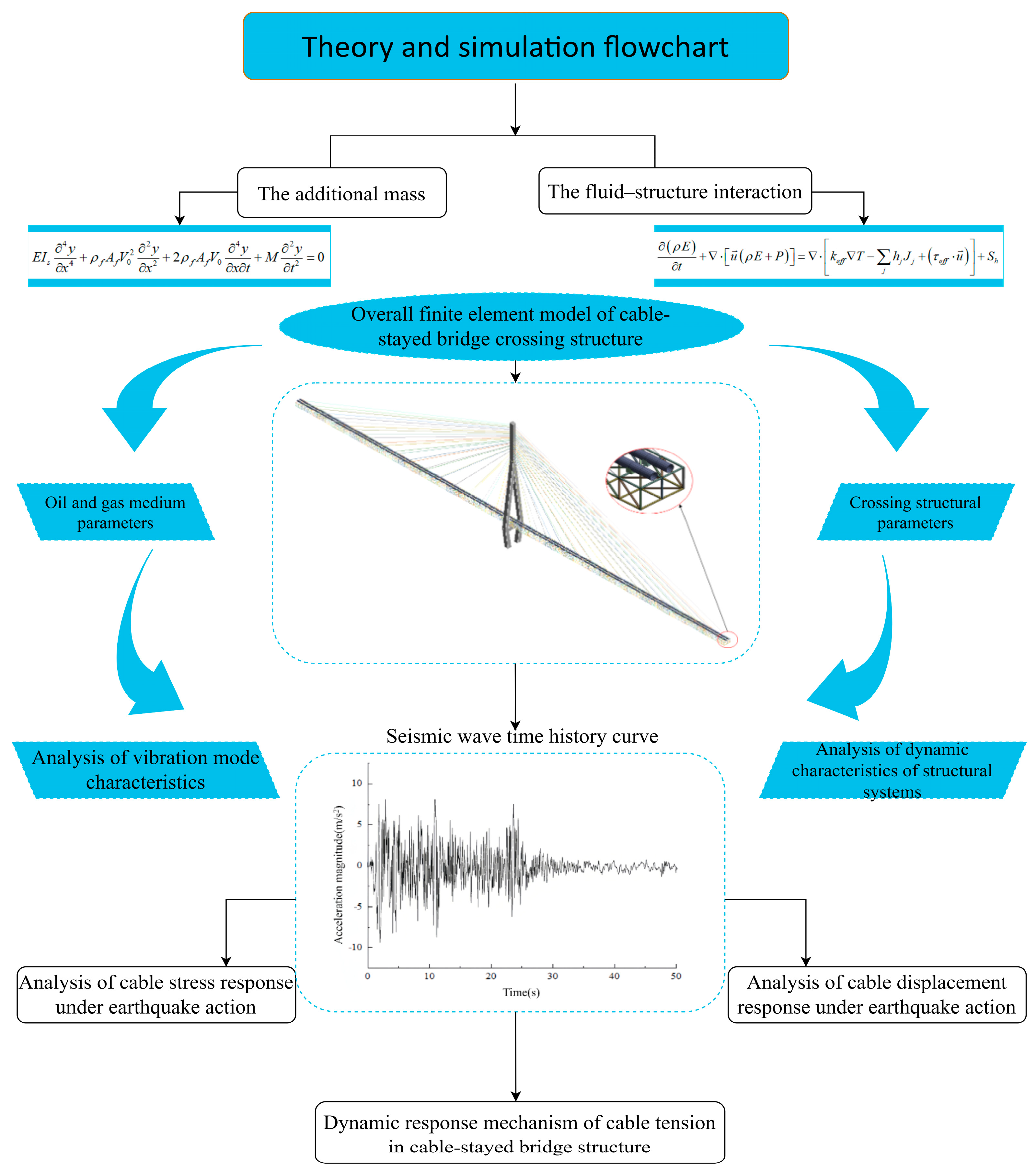
2. Theory and Simulation

The vibration characteristics and dynamic response of the cable as a load-bearing component play a crucial role in the overall safety of the cable-stayed tube bridge. Therefore, in order to fully consider the dynamic effect of the cable under seismic action, the additional mass method and the fluid–solid coupling method are used, respectively, to compare and analyze the dynamic effect of the cable-stayed pipe bridge. In the additional mass method, we accurately describe the dynamic behavior of the cable by considering its own vibration modes and frequencies and further introduce the interaction between the structure and the fluid. This method simulates the effect of fluid inertia on the motion of the bridge by means of additional mass, which enables us to address the problem in an unstructured grid effectively and estimate the influence of the fluid more accurately. However, in actual engineering, it may be due to the limitations of structural form and site conditions, making the operation of additional real quality becomes very difficult. For example, for large cable-stayed bridges, attaching a large amount of real mass will not only increase the self-weight of the structure but also may cause unnecessary effects on other parts, such as the vibration frequency of the cable. The fluid–structure coupling method comprehensively considers the influence of fluid movement and pressure on the force and deformation of the solid structure and pays more attention to the characteristics and changes in the fluid in the pipeline to analyze the dynamic response of the cable under the action of fluid mechanics, including vibration amplitude, frequency, mode, etc.
The additional mass method and the fluid–solid coupling method are used to analyze the effect of the cable-stayed oil and gas pipeline. It is found that the cable-stayed cable not only bears the static tension but also bears the dynamic force caused by fluid flow and pipeline vibration. Therefore, the dynamic effect of the cable-stayed cable is particularly critical. Through these two methods, the specific effect of dynamic action on the cable is deeply studied, and the law governing the correlation between stress and displacement in the cable is revealed. Although the additional mass method is a common method based on specifications, the fluid–structure interaction method can be solved in the flow field and structure, respectively, and the coupling iteration between each time step until convergence, which can avoid the sudden change caused by model simplification or calculation error, so that the analysis results can better simulate the actual situation. The disadvantage is that, in some cases, iterative solutions may not converge or converge slowly, which may increase the difficulty and time cost of solving. As the core force element of the whole structure, the safety of the cable-stayed cable is very important. Once it is improperly affected, it has the potential to cause irreversible damage to the entire structure. The research methods and technical routes are presented in Figure 1.

2.1. Dual Theoretical Framework

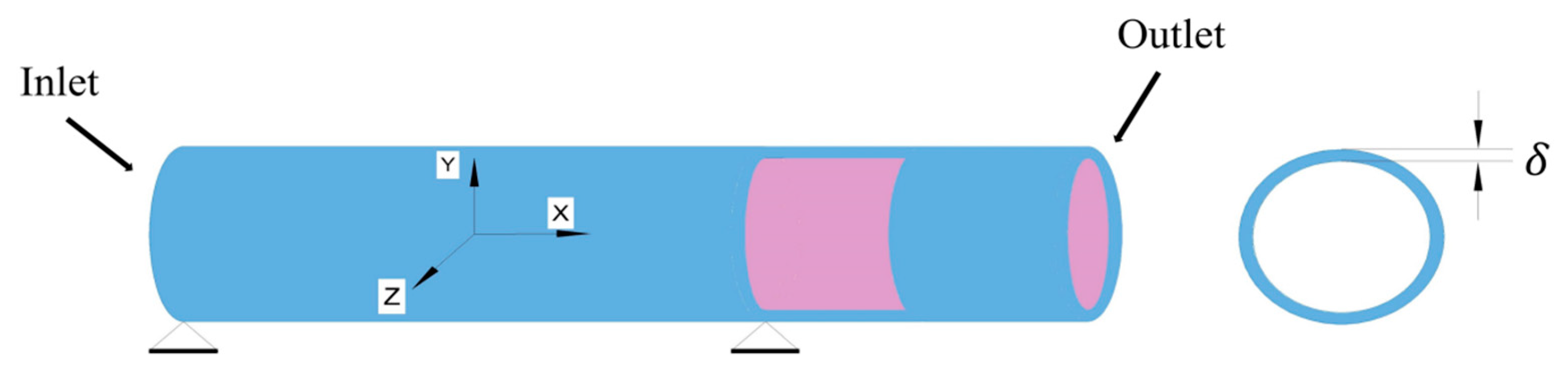
2.1.1. Additive Mass Theory

The force generated by the medium flow in the oil and gas pipeline can be regarded as the additional mass effect of the pipeline for the dynamic response of the pipeline. We can regard the mass of the medium in the oil and gas pipeline structure as the pressure exerted on the inner wall of the oil and gas pipeline so as to solve the dynamic process of the additional mass of the oil and gas pipeline structure [35].
The simplified model of the oil and gas pipeline is shown in Figure 2. Take the fluid element of the pipeline δ x ; then, the balance equation of the fluid element in the pipeline during deformation movement is as follows:
F p A f 2 y x 2 = ρ f A f t + V 0 x 2 y
Moreover,
A f p x + q s = 0 ,
The lateral force balance equation of the pipeline structure element is as follows:
Q x + T 2 y x 2 F m s 2 y t 2 = 0 ,
Moreover,
T x + q s Q 2 y x 2 = 0 ,
The motion equation of pipeline vibration can be obtained by combining Equations (1)–(4):
E I s 4 y x 4 + ρ f A f V 0 2 2 y x 2 + 2 ρ f A f V 0 4 y x t + M 2 y t 2 = 0 ,
where A f is the medium flow area in the tube, p is the medium pressure, ρ f is the medium density, V 0 is the medium flow rate, F is the force on the medium per unit pipe length, q is the shear stress, Q is the shear stress, T is the longitudinal tensile stress, y is the element displacement of the pipe segment, s is the boundary of the inner wall of the pipe, m s is the mass of the pipe per unit length, M is the bending moment of the pipe section, and E I s is the bending stiffness of the pipe section.
The instantaneous quasi-static pressure P of any point on the inner wall of the pipeline at time t is as follows:
P = ρ f V 0 2 2 C p ( x , t ) ,
Considering the pulsation of the fluid movement in the petroleum and natural gas pipeline, add the pulsation coefficient. α = 2 k + 1.414 V 0 k / V 0 2 , where k is the turbulent kinetic energy. From this, the pulsating quasi-static pressure P s can be obtained as follows:
P s = ρ f V 0 2 2 α C p ( x , t ) ,
In the formula, C p ( x , t ) is the pressure coefficient of the medium in the tube
C p ( x , t ) = C p , max ( t ) sin ( n π x l ) ,
where C p , max is the maximum pressure coefficient, and the Fourier expansion can be obtained as follows:
C p , max ( t ) = A 0 + A k cos ω s , n t + B k sin ω s , n t ,
where A 0 , A k , and B k are the Fourier expansion term coefficients, and ω s , n = 2 π f n represents the angular frequency corresponding to the first n mode. Then, the additional mass formed by the quasi-static pressure of the medium in the tube is as follows:
m 0 = 1 2 α ρ f V 0 2 A f y 0 ω s , n 2 ,
where α is the fluid pulsation coefficient, y 0 is the amplitude of the oil and gas pipeline, and A f is the flow area of the oil and gas medium.
The formula for the natural frequency of vibration in the air within an oil and gas pipeline can be derived as follows:
ω s , n = K s m s ,
where K s and m s are the modal stiffness and the mass of the oil and gas pipeline, respectively. When considering the effect of the additional mass of the pressure produced by the oil and gas medium, Formula (11) can be written as follows:
ω f , n = K s m s + m 0 ,
where ω f , n is the coupling frequency under the influence of the oil and gas conveying medium in the oil and gas pipeline. From the ratio of Formulas (11) and (12), the additional mass of the pressure of the oil and gas medium on the oil and gas transmission pipeline can be obtained:
M 0 = f s , n f f , n 2 1 m s ,
where f s , n is the natural frequency of the first n mode of the oil and gas pipeline, and f f , n is the natural frequency of the first n fluid–structure interaction vibration.

2.1.2. Fluid–Structure Interaction Theory

In the process of pressure flow in the oil and gas pipeline, when the fluid is in contact with the solid phase, the solid will be subjected to the force of the fluid to deform the structure. In general, the structural deformation undergoes minimal changes and gradually progresses over time, so it can be considered that this effect is relatively stable. However, under the action of an earthquake, the severe vibration of the pipeline will produce large deformation, which will affect the load distribution of the fluid in the pipeline, and the speed and pressure field of the fluid will change, resulting in changes in the motion state of the medium in the pipeline, which will induce the deformation of the pipeline and lead to new changes in the medium. The effect of the interaction between the fluid medium inside the tube and the solid structure of the pipeline is referred to as the phenomenon of fluid–structure interaction.
According to the mechanism of fluid–structure interaction, two distinct manifestations can be discerned. One is that the solid domain and the fluid domain blend together in whole or in part, namely it is difficult to distinguish between each other, such as turbulence, seepage, and other related problems. The other is that the coupling of the solid and fluid domains is at the junction of the two. The coupling type of the oil and gas pipeline in this study belongs to the second manifestation.
According to whether the data need to be transmitted back and forth in the interface between fluid and solid, the problem of fluid–structure coupling can be classified into unidirectional fluid–structure coupling and bidirectional fluid–structure coupling. Fluid–structure interaction in a single direction implies that the influence of solids on the fluid is not enough to change the shape of the flow field and does not cause deformation and displacement to the fluid; the computation solely focuses on the unidirectional transmission of data from the fluid to the solid. This method is suitable for situations wherein the fluid has a great influence on the solid structure and the solid has negligible influence on the fluid, so this calculation method will lead to inaccurate results. Bidirectional fluid–solid coupling means that the direction of data transfer is bidirectional between the coupling surface of the fluid and the solid state, and the interaction between the fluid and the solid state needs to be considered. This method is consistent with the actual law, and the calculation results will be more accurate, so this study adopts the two-way fluid–structure interaction to simulate the impact of the interaction in the pipeline, within the medium of oil and gas.
The numerical simulation of convection–solid coupling should adhere to the fundamental equations of fluid mechanics and solid mechanics, encompassing the governing equation for fluids, the governing equation for solids, and the equation for coupling control [36].
  • Fluid control equation:
When fluid is in motion within a conduit, it must adhere to fundamental principles of conservation, encompassing the conservation of mass, momentum, and energy.
  • Equation of conservation of mass:
    ρ t + ρ u x x + ρ u y y + ρ u z z = 0 ,
    where ρ is the density; t is the time; and u x , u y , u z are the velocity components in the three directions x , y , z , respectively.
  • Momentum conservation equations:
    ρ u x t + ρ u x u = P x + τ x x x + τ x y y + τ z x z + ρ f x ρ u y t + ρ u y u = P x + τ x x x + τ y y y + τ z y z + ρ f y ρ u z t + ρ u z u = P x + τ x z x + τ y z y + τ z z z + ρ f z ,
    where is the Hamiltonian differential operator, = i / x + j / y + k / z ; P is the pressure on the surface of the fluid element; f x , f y , f z are the unit mass forces in the x , y , z directions, respectively; and τ x x τ x y τ z x are the components of the viscous stress τ on the surface of the element.
  • Energy conservation equation:
    ρ E t + · u ρ E + P = · k e f f T j h j J j + τ e f f · u + S h ,
    where E is the total energy of the fluid, k e f f is the effective heat conduction coefficient, h is the enthalpy, h j is the enthalpy of component j , J j is the diffusion flux of component j , and S h is the chemical reaction heat and other user-defined volume heat source terms.
  • Governing equations for solids:
The governing equations for solids can be derived from Newton’s second law as follows:
ρ s d ¨ s = · σ s + f s ,
where ρ s is the solid density, d ¨ s is the solid acceleration, σ s is the Cauchy stress tensor, and f s is the volume force vector.
  • The governing equation of fluid–structure interaction:
Properly organizing the fluid and solid domains is crucial for accurately calculating pipeline fluid–structure interaction problems. Therefore, it is imperative to precisely determine the interface where the fluid and solid interact, ensuring that both the kinematic balance equation and dynamic balance equation are satisfied at this coupling boundary between the two domains and that the solid domain is met at the same time [37]:
d f = d s τ f · n f = τ s · n s ,
where d f and d s are the boundary displacements of the fluid and solid, respectively; τ f and τ s are the shear force vectors of the fluid and solid, respectively; and n f and n s are the numbers of nodes of the fluid and solid, respectively.

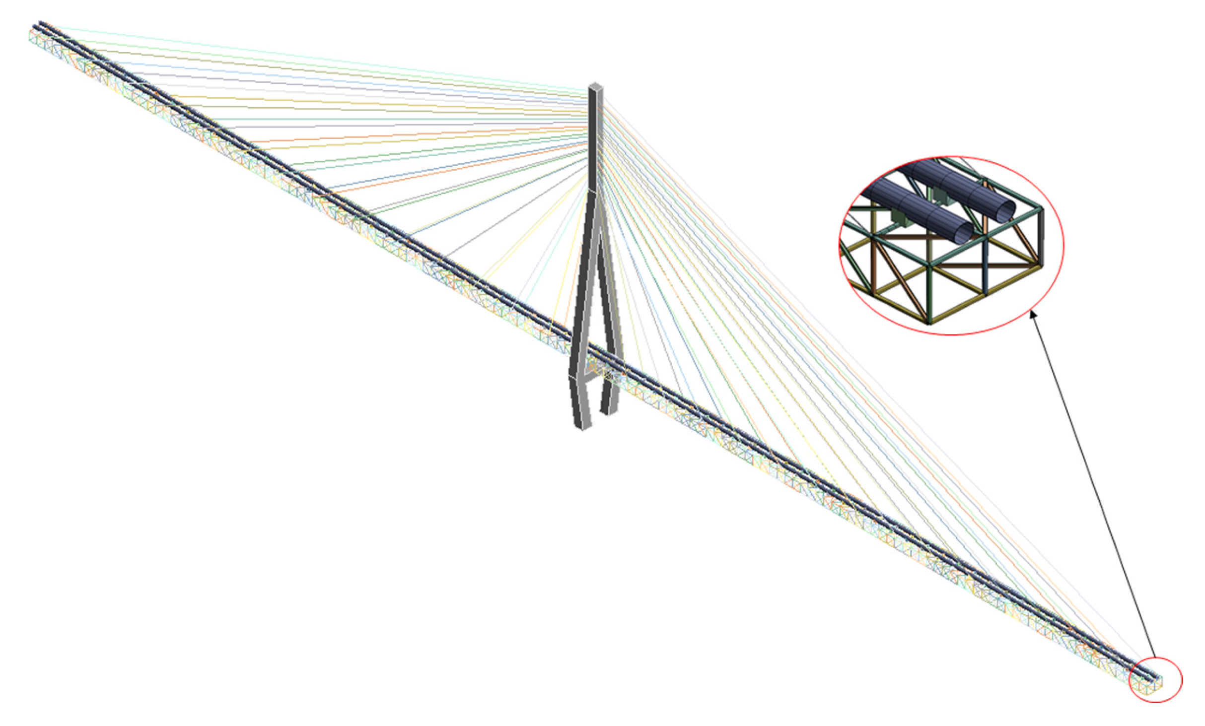
2.2. A Finite Element Model of Straddling Oil and Gas Pipelines

The span-type oil and gas pipeline structure adopts a combination of a cable-stayed bridge and an oil and gas pipeline phase. Compared with a cable-stayed bridge, the deck of the cable-stayed bridge is changed into a petroleum and natural gas pipeline and truss beam, and the oil and gas pipeline is set parallel to the truss beam as the force element. Compared with a highway cable-stayed bridge, the deck width of the cable-stayed pipe structure is smaller, the petroleum and natural gas pipeline and self-weight are smaller, the bridge flexibility is larger, and the influence of dynamic load is greater. Of most significance is that the stress state is different: the pipeline is under horizontal tension, and the deck of the cable-stayed bridge is under horizontal compression. The whole structure of the bridge system is made of steel, which has the characteristics of a cable-stayed bridge. In this section, the cable-stayed pipe bridge structure system is simplified on the existing basis, and the full-scale finite element model of the structure is established.

Types and Parameters of Each Component of the Cable-Stayed Tube Bridge

In this study, the oil and gas transmission pipeline erected on a single-tower double-cable-plane cable-stayed pipe bridge is investigated. Based on the obtained findings, a prototype of a cable-stayed pipe bridge–oil and gas pipeline system was established. The finite element model in three dimensions, which accurately represents the entirety of the bridge, was established with ANSYS Workbench19.0. The structure is composed of a cable-stayed cable, a tower, a truss beam, a support, and a pipeline.
The model is a single-tower cable-stayed structure with a bridge tower height of 72 m and a vase structure. The width of the truss beam is 0.284 m, which is composed of a vertical rod, a chord rod, and an oblique belly rod. The length of each truss beam is 2 m, and each of the two trusses is arranged with a support. Double pipes are used to transport oil and gas and are set up parallel to the truss beam support. The pipeline specifications are Φ 711 × 12.7 mm, with a total length of 284 m, and the bridge span layout is 142 m + 142 m. Cable-stayed cables are arranged in a fan-like manner using a 6 × 37 galvanized steel wire rope. The basic cable distance is 10 m, while the distance of the cable on the bridge tower measures 1.5 m. The specifications are Φ 25.5 , Φ 36 , Φ 42 , and Φ 45 . The model has a total of 77,582 nodes and 14,414 units. As shown in Figure 3.
The composition and mechanical characteristics of each constituent element within the cable-stayed pipe bridge structure are shown in Table 1.

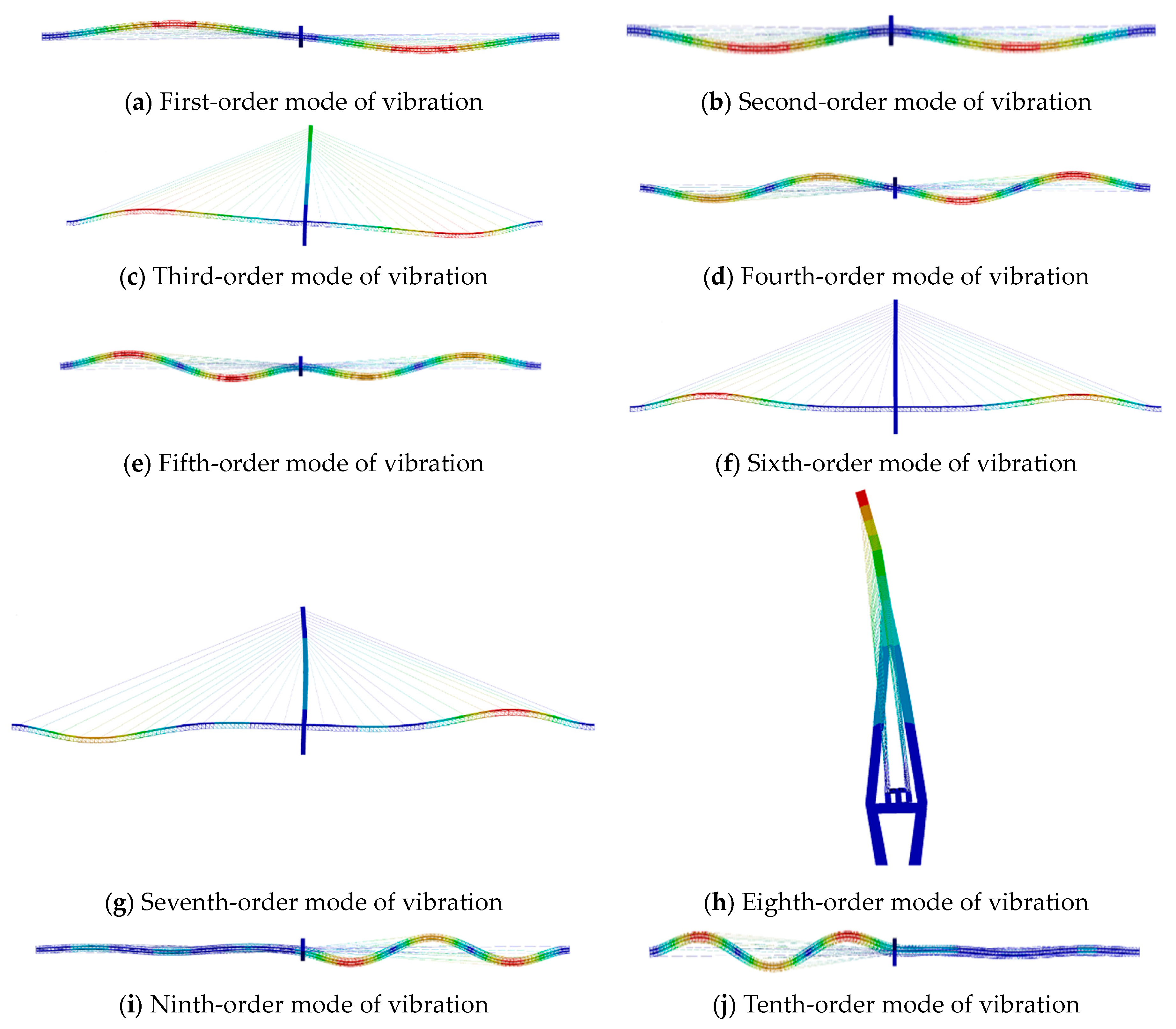
2.3. Analysis of Structural System Dynamic Characteristics

The dynamic characteristics of the structural system are the inherent attributes of the structure per se, also known as the natural vibration characteristics of the structure, which generally refer to the period of the structure, damping, natural vibration frequency, and its corresponding vibration mode, while the fundamental factors that impact the intrinsic vibration characteristics of the structure are structural materials, structural stiffness, structural quality, and structural boundary conditions. The inherent resonance characteristics of the structure are the basis of dynamic analysis, and the stiffness distribution of the structural system obtained through analysis also plays a crucial part in the seismic design and wind stability analysis of the pipe bridge structural system. Therefore, the investigation of the inherent vibrational characteristics of the structure and the solution of the structure’s natural vibration frequency and mode are of great importance to both theory and practice.
The kinematic differential equation of structure in dynamic analysis can be articulated as follows [38]:
m u ¨ + c u ˙ + k u = F t ,
where m is the mass matrix; c is the damping matrix; k is the stiffness matrix; F t is the external load vector; and u ¨ , u ˙ , and u are the acceleration vector, velocity vector, and displacement vector, respectively.
In modal analysis, the load F t is 0, and when the damping of the structure is ignored, the free vibration equation without damping can be obtained:
m u ¨ + k u = 0 ,
Assume a multi-freedom structure system for simple harmonic vibration:
u t = ϕ sin ω t + θ ,
where ϕ is the system shape of the structure, and θ is the phase angle.
The acceleration of free vibration of the structure can be obtained by quadratic derivation of the formula:
u ¨ t = ω 2 ϕ sin ω t + θ ,
Substituting Equations (20) and (21) into Equation (19) and eliminating the sine term gives
k ω 2 [ M ] ϕ = 0 ,
The first few modes of the structural system can be obtained by solving the first few frequencies and modes of Formula (23).
Although the structure forms and boundary conditions of the pipe bridge with cable-stayed design and the highway cable-stayed bridge are different, they all have the same vibration forms, including transverse vibration, longitudinal vibration, vertical vibration, and torsion, or a random combination of the four forms. However, under normal circumstances, the primary determination of the dominant vibration mode in the structure will be based on one of the four main vibration modes, and the structure is often manifested as a certain form of vibration mode.
When analyzing the dynamic properties of the structural system, because the low-order frequency and the dynamic analysis of the structure are significantly affected by the mode, the high-order mode with a small probability is usually ignored, and the modal characteristics and lower frequency range of the structure are mainly analyzed. Therefore, this study mainly discusses the low-order natural vibration characteristics of the structure. Based on the Modal module in ANSYS Workbench software, the first 10 natural vibration frequencies and modal vibration types of the structural system are obtained. Table 2 lists the initial ten frequencies of natural vibrations and modal characteristics of the system. The specific modal changes are shown in Figure 4.
As can be seen from Table 2 and Figure 4, the dynamic characteristics of the structural system are summarized as follows:
  • The cable-stayed straddling oil and gas pipeline structure is a flexible structure, the natural frequency of dynamic characteristics is small, and the distribution of the first 10 orders of natural frequency is relatively dense. Such structures belong to a dense frequency structure, which indicates that the vibration characteristics of the cable-stayed straddling oil and gas pipeline are complex, and a comprehensive investigation of the mechanical properties of the cable is imperative under earthquake action.
  • Comparing and analyzing the first 10 vibration modes of the cable-stayed span structure of pipelines for oil and gas transportation, the occurrence of vibration modes primarily manifests in pairs, as is evident, with the characteristics of positive symmetry or antisymmetric. The transverse bending of the main beam is more than that of the vertical bending, which indicates that the transverse stiffness of the main beam in the structural system is smaller than the vertical stiffness. Therefore, in the following seismic response and analysis of harm, the focus is placed on the impact of transverse seismic waves on both the structure and cable.
  • The main beam’s bending in the transverse direction mainly occurs on both sides of the span, showing a symmetrical structure as a whole, and the flexing of the primary girder also directly affects the displacement change in the cable. Therefore, when analyzing the response of the cable, it is necessary to study the dynamic effect of the cable corresponding to the mid-span position of the left and right sides.

3. Results

The cable-stayed pipe bridge structure system discussed in this study is located within the eight-degree region, classified as a class II site, with a characteristic period of 0.35. Therefore, we have opted to employ the EI-Centro seismic wave from recorded data as our input seismic wave. This study mainly discusses the damage mechanism of the structure and cable in the event of a significant seismic occurrence, so the seismic wave that undergoes the maximum acceleration is modified to 10.0 m / s 2 , the duration of the earthquake is 50 s , and the temporal interval is 0.02 s . The pipe–bridge structure in this study only considers the case of the consistent excitation input of seismic waves.

3.1. Analysis of Time-History Response of Cable under Earthquake Action

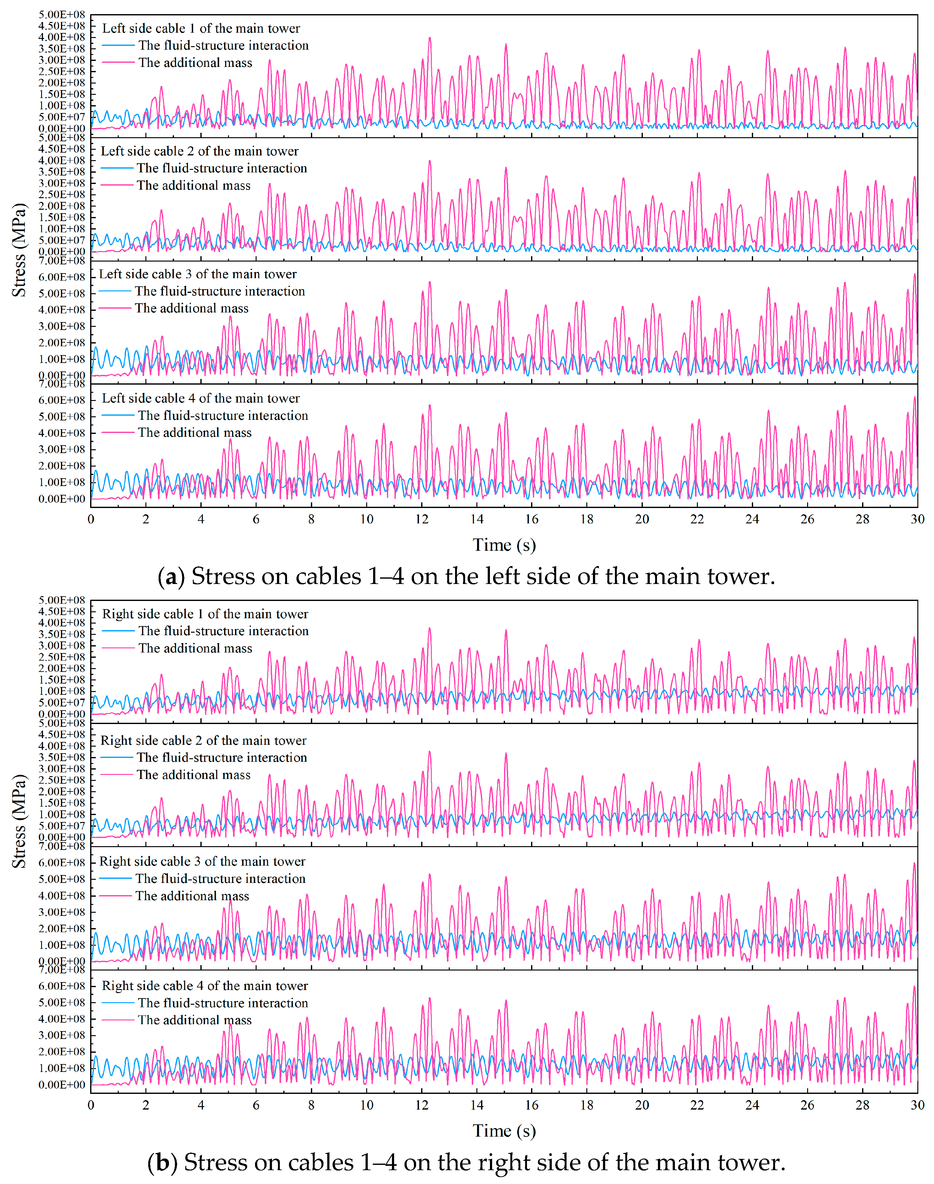
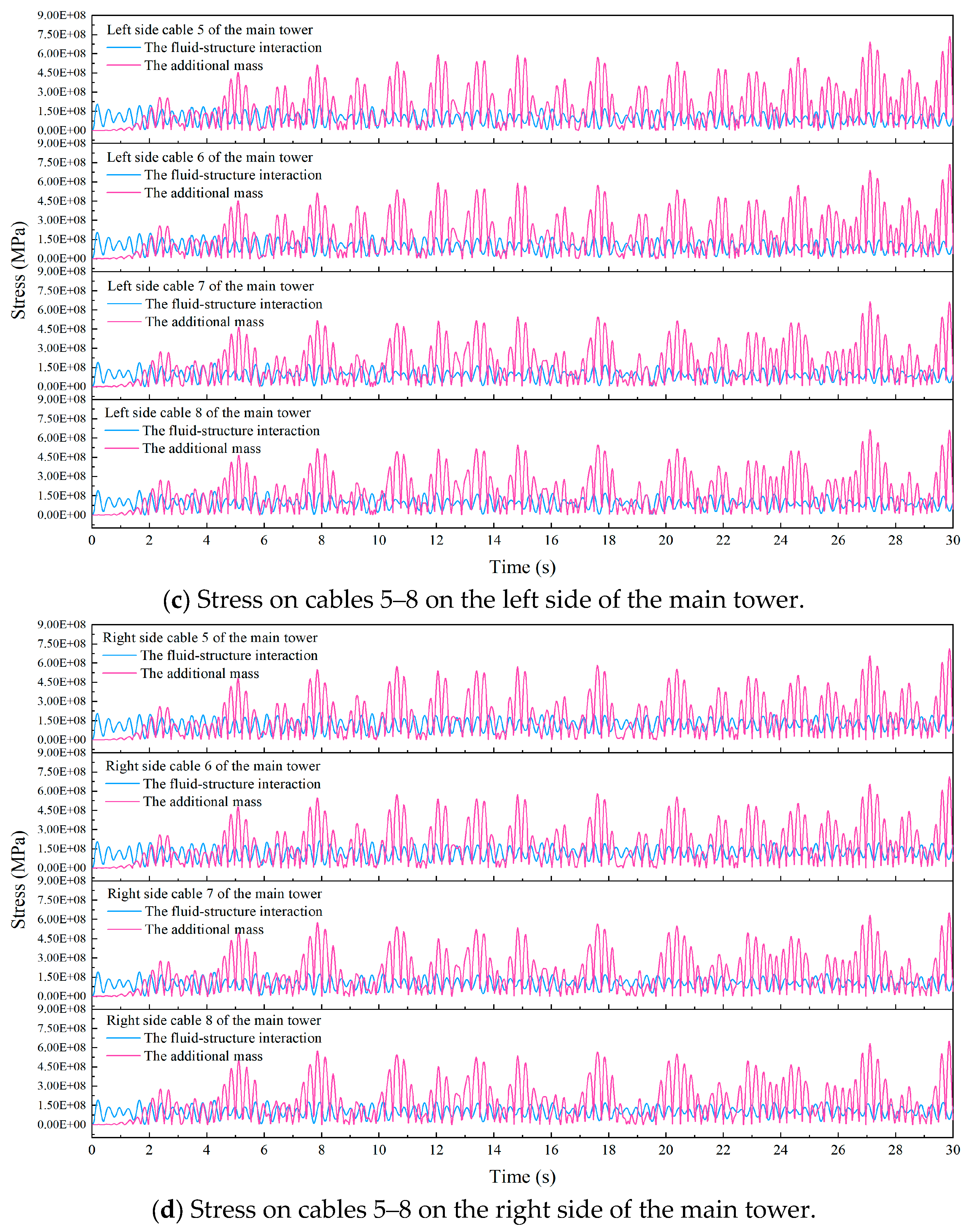
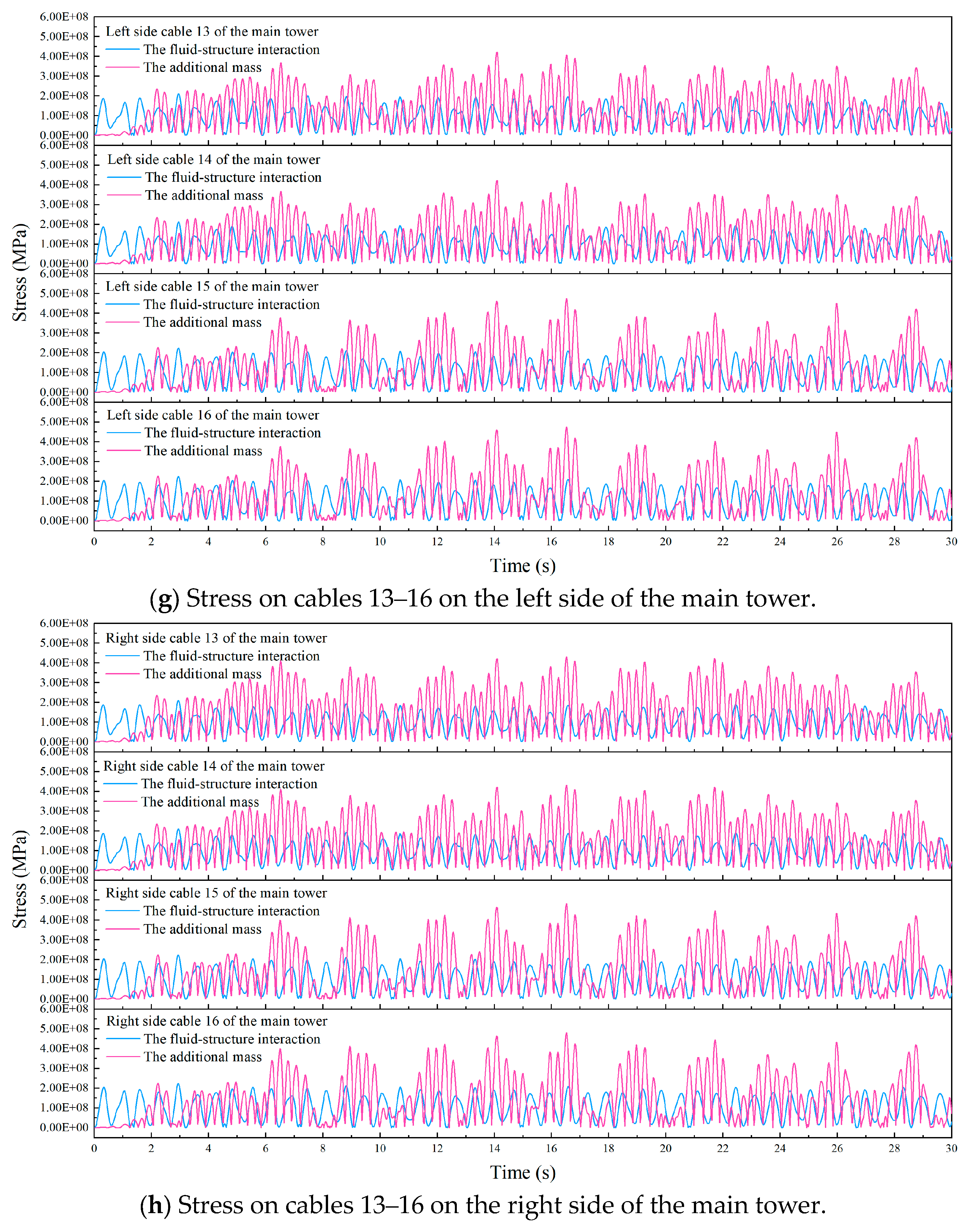
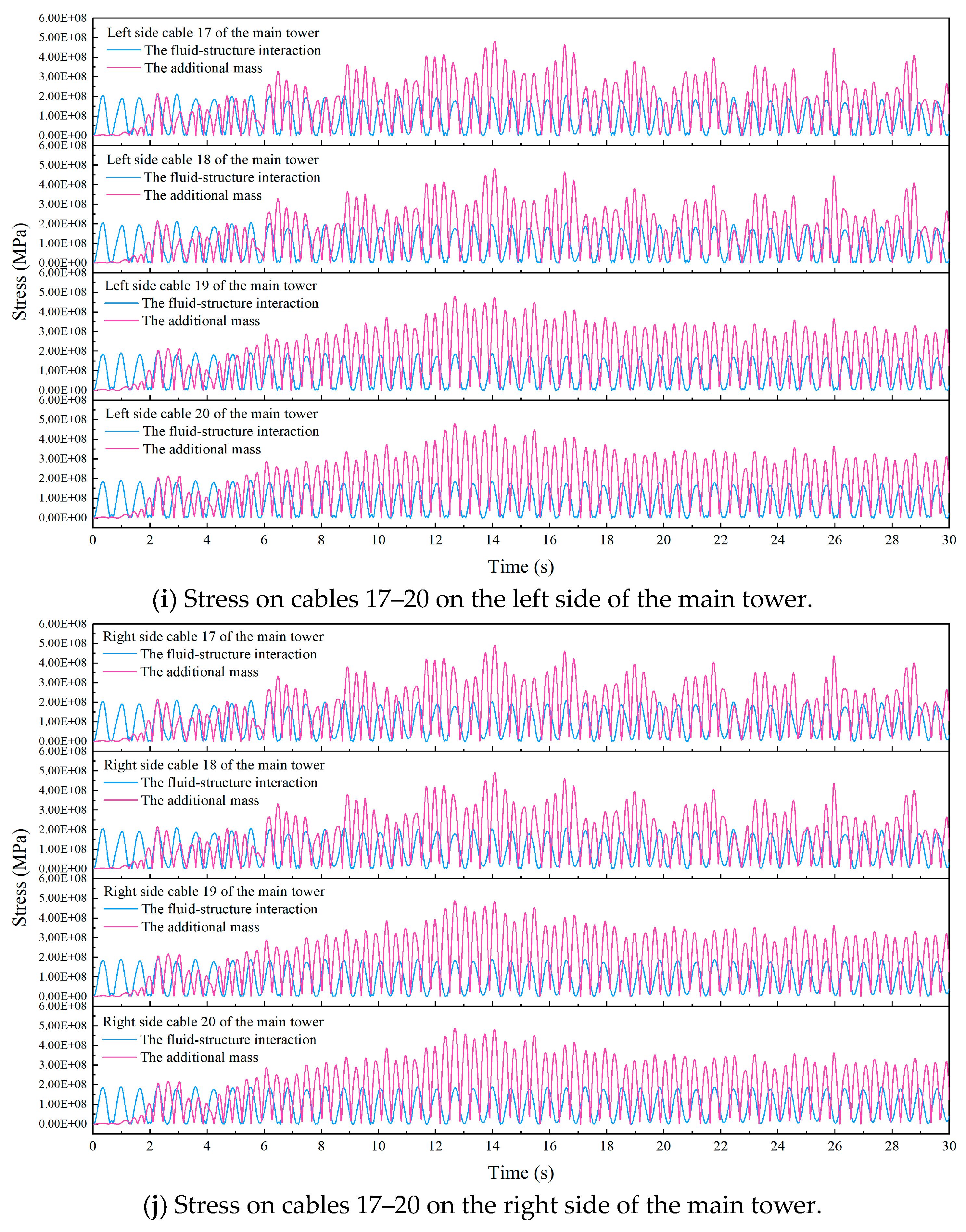
3.1.1. Cable Stress Response Analysis

The dynamic response of the cable-stayed pipe bridge subjected to seismic excitation was investigated utilizing the additional mass method and fluid–structure coupling approach. The results pertaining to the analysis of cable stress response are depicted in Figure 5 and Table 3.
The analysis of Figure 5 and Table 3 reveals the following conclusions. Under the action of the flow–solid coupling method, the maximum stress time region of the structure is antisymmetric on both sides, and the maximum stress time of the cable on both sides of the main tower mainly focuses on 0–3 s in seismic waves; however, under the action of the additional mass method, the left and right sides of the maximum stress time area of the structure show positive symmetry, and the maximum stress time on both sides of the main tower in the seismic wave is concentrated in the ranges of 12–15 s and 29–30 s.

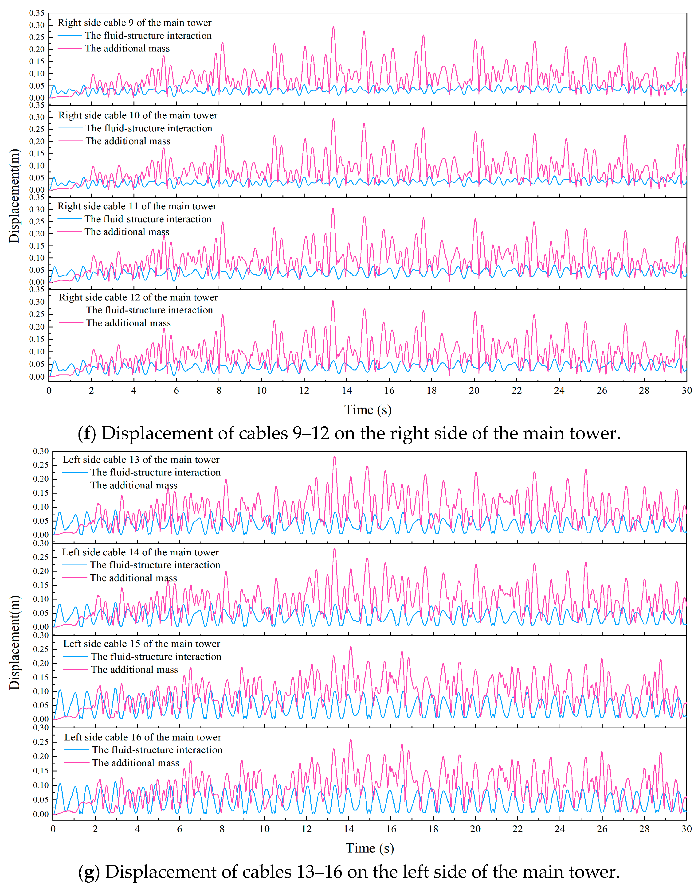
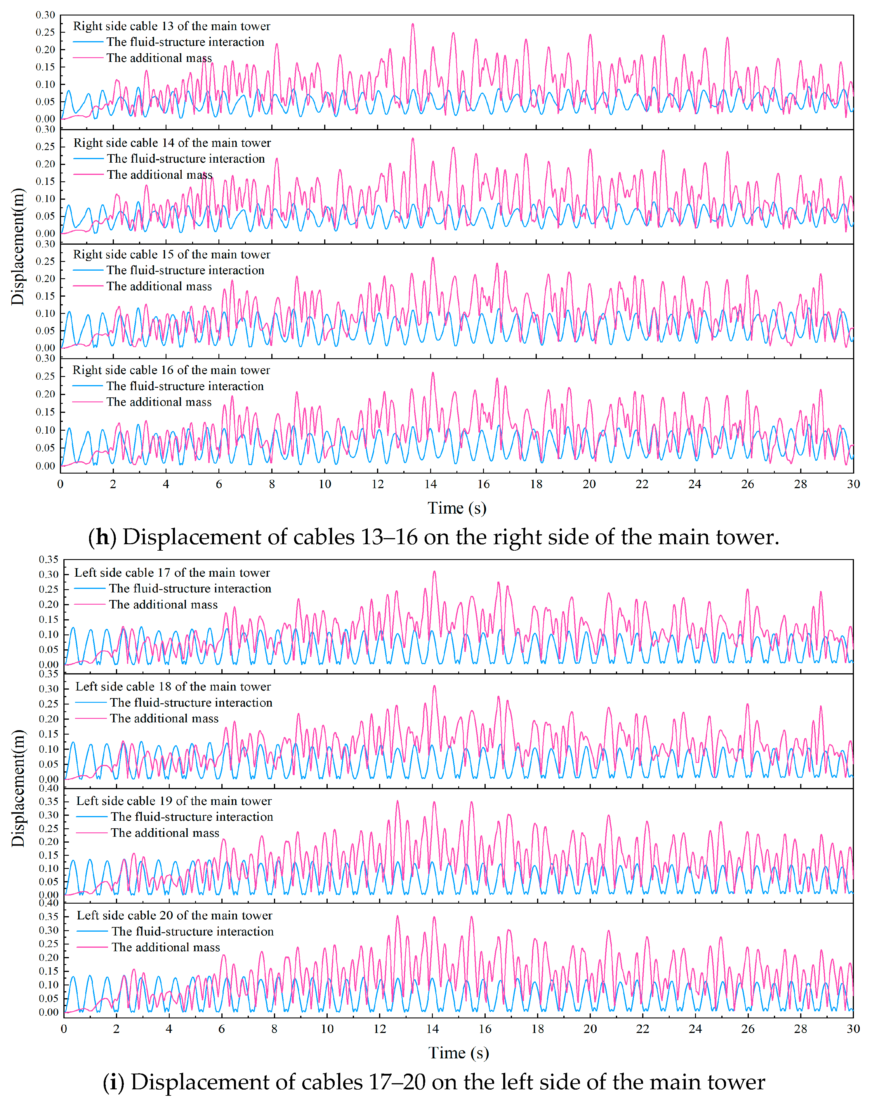
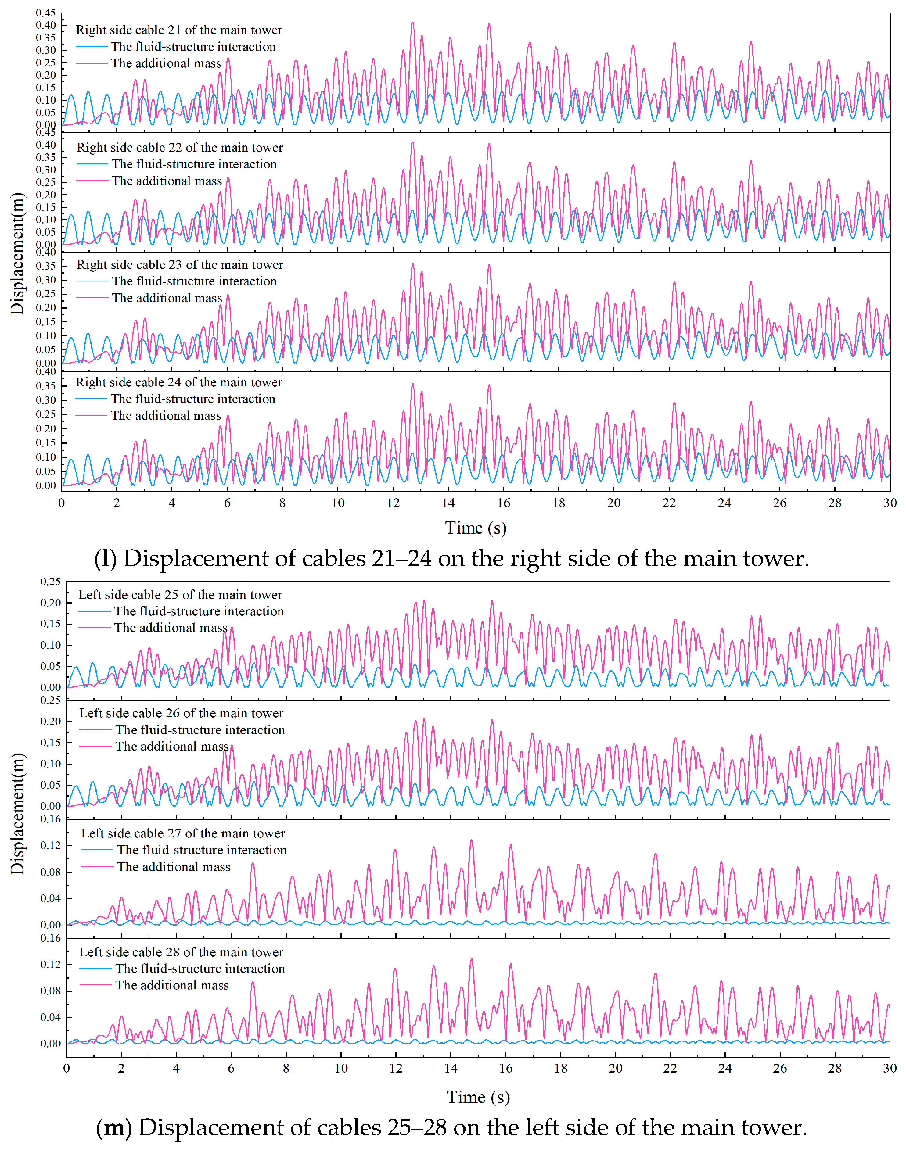
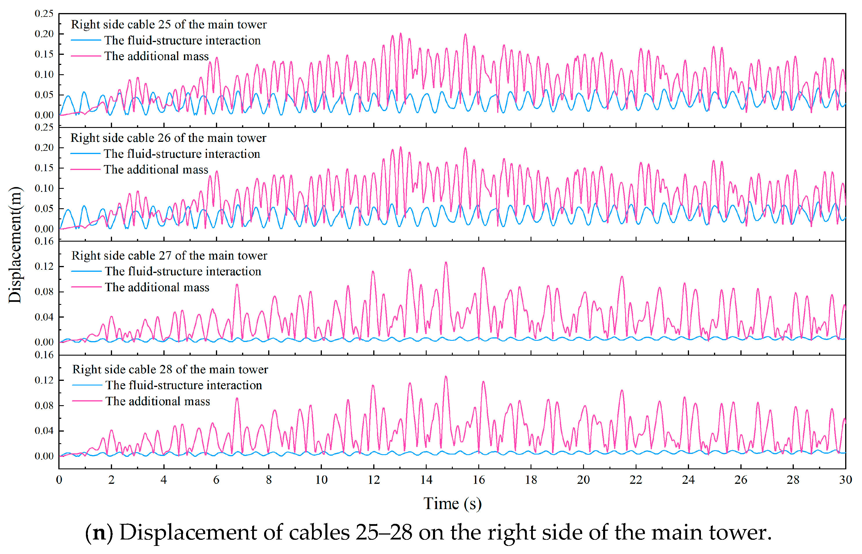
3.1.2. Analysis of Cable Displacement Response

The dynamic response of the cable-stayed pipe bridge subjected to seismic excitation was investigated utilizing the additional mass method and fluid–structure coupling approach. The results pertaining to the analysis of cable displacement response are depicted in Figure 6 and Table 4.
Through the analysis of the above data, it can be seen that the cable stress and displacement results obtained by the fluid–structure coupling method under the action of seismic waves are smaller than those obtained by the additional mass method. Compared with the 10-order vibration mode data of the above-mentioned cable-stayed pipe bridge, it can be seen that the law presented by the dynamic analysis results essentially aligns with the vibration mode analysis results, and the displacement and vibration mode are basically paired and have the characteristics of positive symmetric and antisymmetric bending. It is evident from Table 4 that the structure exhibits transverse bending under the fluid–structure interaction method, which mainly occurs at both sides of the span, while the transverse bending of the structure under the additive mass method mainly occurs in the middle of the span, which is consistent with the mode of vibration seen in Figure 4.
The stress and displacement by both the left and right sections of the primary tower under the fluid–structure interaction method show asymmetric causes: In the presence of seismic waves, the fluid force may exhibit asymmetry, resulting in the fluid pressure and moment on both sides of the main tower. This asymmetric fluid force causes the main tower to twist or bend so that the stress and displacement on both sides of the cable show an antisymmetric distribution. In addition, the damping and stiffness of the two sides of the main tower may be different, which in turn leads to different vibration responses on both sides so that the displacement and stress on both sides show an antisymmetric distribution.
The stress and displacement in both the left and right sections of the primary tower under the action of the additive mass method show symmetry due to the following causes: Due to the design and construction of the main tower, the cables on both sides are usually exactly the same, and the distribution is symmetrical. Therefore, under the action of seismic waves, the forces and displacements on both sides of the cable will also show symmetry; at the same time, the energy of seismic waves disperses in all directions simultaneously during their propagation. For the wave perpendicular to the main tower, its propagation direction is perpendicular to the cable on both sides, resulting in similar wave effects on the cable on both sides, and the displacement and stress on both sides present a positive symmetric distribution. Secondly, the cable has a certain stiffness and damping, which can absorb and dissipate the energy of the wave. Since both sides of the cable have the same characteristics, their response to seismic waves is similar.

3.2. Analysis of Distribution Law of Cable Properties under Earthquake Action

3.2.1. Cable Stress Change Distribution Law Analysis

Through the analysis of Figure 7, it can be seen that the laws are as follows:
  • Due to the interaction between the fluid’s flow characteristics and the bridge’s structural properties, both approaches result in an almost symmetrical distribution of stress on either side of the structure.
  • Under the action of fluid–structure coupling, the stress distribution in the left (right) side span is large and stable, while the stress distribution on both sides is small. The maximum value appears in cables 15 and 16, and the minimum value appears in cables 27 and 28. Under the additional mass method, the left (right) side span distribution stress is larger in front of the middle of the span, and on both sides of the span distribution, the stress is smaller. The maximum value appears in cables 5 and 6, the minimum value appears in cables 27 and 28, and the stable region is distributed in the middle and behind the span (cables 15–22).
  • The overall uniformity of the left (right) side of the main tower by the fluid–structure interaction method is less than that by the additional mass method. Compared with the sudden and uneven distribution of cable stress under the additional mass method, the stress of the cable under the fluid–structure interaction is more stable and has no sudden change. The maximum stress under the fluid–structure interaction is nearly 70% smaller than that under the additional mass.

3.2.2. Analysis of Distribution Law of Cable Displacement Change

Through the analysis of Figure 8, it can be seen that the laws are as follows:
  • As a symmetrical structure is adopted in the design of the cable-stayed pipe bridge, the two sides of the structure produce similar displacement distribution under the action of the two methods, and the left and right sides are almost symmetrical.
  • Under the two methods, the large displacement area of the left (right) side of the structure is concentrated in the middle of the span; the maximum displacement occurs in cables 21 and 22, the cable distributed on both sides of the span has a small displacement, and the minimum displacement occurs in cables 27 and 28.
  • The displacement size of the left (right) side of the main tower using the fluid–structure interaction method is less uniform than that using the additional mass method. Unlike the additional mass approach, the displacement of the cable reaction under fluid–structure coupling is relatively stable, and there is no abrupt change. In addition, the maximum displacement value under the fluid–structure coupling is reduced by nearly 67% compared to the maximum displacement value under the additional mass.
  • According to the analysis of Figure 7, it is evident from the data that the fluid’s impact can reduce the response of the structure and play a buffer role, thus reducing the vibration of the structure and making its deformation smaller, which is also the reason why the stress and displacement on both sides of the main tower under the fluid–structure coupling are smaller than the additional mass. Especially under the external excitation of natural disasters such as earthquakes, wind loads, and water loads, the fluid–structure interaction method can reflect the change in structural stiffness to better reflect the vibration characteristics of the structure. By simulating the dynamic interaction between the fluid and the structure, the vibration mechanism of the structure can be predicted more accurately, revealing a closer approximation to the actual circumstances.

4. Conclusions

In this study, the finite element calculation software ANSYS Workbench was utilized to compare and analyze the dynamic properties and response of the cable-stayed pipe bridge structure. The method of incorporating additional mass and the approach considering the fluid–structure interaction and the dynamic response characteristics and variation rules of the cable-stayed cable in the dynamic response of the cable-stayed pipe bridge were explored. The findings are as follows:
  • By establishing a three-dimensional geometric model in the realm of finite element analysis, setting the parameters of the structural components, selecting the material constitutive model, and setting the fluid–structure coupling model, it is evident that the stress and displacement on the left and right sides of the structure show an antisymmetric distribution, which is mainly due to the asymmetry of the fluid force and the difference between the damping and stiffness on both sides of the main tower. Through the analysis of vibration modes, it can be seen that, as a flexible structure, the cable-stayed straddle oil and gas pipeline has complex vibration characteristics and a small natural frequency. The vibration modes of such tight-frequency structures are mostly positive-symmetric or antisymmetric. It is especially significant in the transverse flexure of the primary girder, indicating that its transverse stiffness is relatively small. Therefore, the impact caused by the influence of lateral fluctuations should be given special consideration on the main beam and cable, especially the dynamic effect of the cable in the middle of the span on both sides.
  • By analyzing the distribution of cable stress under earthquake action, it is evident that, compared with the additional mass method, the left (right) side stress of the main tower under the method of interaction between fluid and structure is generally smaller, and its maximum stress value is reduced by nearly 70%. Under the two methods, the cable on both sides of the structure shows a small stress response. Further data indicate that the implementation of the fluid–structure interaction technique results in a predominant concentration of high stress levels within the mid-span part of the structure, and the amplitude difference in the stress is small, showing a stable reaction phenomenon with small sudden changes. In contrast, when the additional mass method is adopted, the structural stress under the action of seismic waves is mainly distributed on both sides of the span of the structure, the difference between the stress and the deformation amplitude is significant, and the data show instability accompanied by sudden change.
  • Through the analysis of the distribution of cable displacement under earthquakes, it is evident that whether the methodology for the interaction between fluids and structures or the additional mass method is adopted, the area with large cable displacement is primarily located in the middle portion of the structure and back parts of the span, and the displacement generated by the cable distributed on both sides of the span is small. Further data show that, compared with the additional mass method, the displacement results to the left (right) of the central tower under the fluid–structure interaction method are smaller, and the displacement response of the cable has better stability without abrupt changes. According to the fact that the maximum displacement value is nearly 67% lower than that of the additional mass methods, the structural response can be effectively mitigated by the impact of fluid and play a buffer effect to reduce the vibration and deformation of the structure, which provides greater advantages for the structure. Secondly, due to the role of the fluid, the stiffness of the structure will change. The fluid–structure interaction method can simulate this stiffness change to better reflect the dynamic properties of the structure. Through the simulation of the interaction between the fluid and the structure, we can more accurately reveal the expected dynamic response of the structure, closer to the real circumstances, to better design the structure or take other measures to reduce the stiffness of the structure. In the fluid–structure interaction method, we can better study the dynamic reaction mechanism of the cable-stayed tube bridge structure under earthquake action to provide a reference for the cable-stayed tubular bridge’s design and analysis under seismic load.

5. Proposals for Future Research

  • The fluid–structure coupling problem entails intricate interaction between the fluid and the solid, thereby making the calculation process complex and requiring extensive data and boundary conditions to be processed. In this process, we are premised on the assumption that both the fluid and the solid are continuous media and, to a certain extent, overlook the disparities in their microstructures. Given the multiplicity of damages brought about by structural vibration, on the basis of discussing the dynamic response mechanism of the cable-stayed tube bridge structure in detail, we should carry out long-term dynamic monitoring of the cable-stayed tube bridge and collect the actual response data under dynamic load, thereby fine-calibrating and optimizing the existing finite element model. Additionally, cutting-edge approaches such as advanced materials, innovative optimization of structural design, and active control technology need to be explored to identify more effective vibration reduction and protection measures so as to significantly decrease the vibration amplitude and frequency of the cable and, accordingly, enhance the overall safety and durability of the cable-stayed tube bridge.
  • The impact of earthquakes on structures is complex and nonlinear. The core of this study is the structural vibration caused by ground motion, which is manifested as the external load directly acting on the structural system in the form of inertial force. However, under this dynamic action, structures such as the cable will experience elastic–plastic deformation, damage to material properties, and nonlinear interactions between contact surfaces. In addition, by using the additional mass method, we assume that the response of the cable is linear and the additional mass is evenly distributed on the cable, so we ignore the influence of nonlinear factors on the dynamic reaction and the uneven mass distribution that may exist in practical engineering, etc., so If only the linear analysis method based on inertial forces is used, the effect of these nonlinearities may be overlooked. Therefore, future research must further analyze the nonlinear dynamic characteristics of the structure while exploring how the structural system responds to the site vibration.
  • In this study, we adopted a simplified, consistent incentive input method. However, according to the depth of the current academic research, this method of consistent incentive input, to some extent, ignores the propagation speed of seismic waves and the subtle time difference generated when the different support points receive the seismic wave, the so-called traveling wave effect. For long-span bridge structures such as cable-stayed pipe bridges, the time for seismic waves to reach their various support points may be significantly different. Therefore, it is necessary to further explore and study the correlation analysis under multi-point excitation to ensure that the safety and stability of the structure are fully considered.

Author Contributions

X.Z.: formal analysis, testing, methodology, and conceptualization. Y.J.: validation, visualization, testing, software, and editing. G.W.: formal analysis, testing, and methodology. All authors have read and agreed to the published version of the manuscript.

Funding

The financial support for this work was provided by the National Natural Science Foundation of China (No. 52174061), the Key Research and Development Program of Shaanxi (Program No. 2022GY-431), and the Xi’an Shiyou University Youth Science and Technology Innovation Fund Project (2015BS55).

Data Availability Statement

The original contributions presented in the study are included in the article, further inquiries can be directed to the corresponding author.

Acknowledgments

The authors would like to thank Xiyu Zhu of the School of Civil Engineering, Xi’an Shiyou University, for helpful discussions on topics related to this work.

Conflicts of Interest

The authors declare no conflicts of interest.

References

  1. Pakos, W.; Grosel, J. Reduction of cable vibrations in a cable stayed bridge under biharmonic excitation. Eng. Struct. 2019, 189, 1–10. [Google Scholar] [CrossRef]
  2. Jeong, S.; Lee, J.; Cho, S.; Sim, S.H. Integrated cable vibration control system using Arduino. Smart Struct. Syst. 2019, 23, 695–702. [Google Scholar]
  3. Meng, X.; Zhang, B.; Cao, F.; Liao, Y. Effectiveness of Measures on Natural Gas Pipelines for Mitigating the Influence of DC Ground Current. IEEE Trans. Power Deliv. 2024, 1–9. [Google Scholar] [CrossRef]
  4. Abdel-Ghafar, A.M.; Khalifa, M.A. Importance of cable vibration in dynamics of cable-stayed bridges. J. Eng. Mech. 1991, 117, 2571–2589. [Google Scholar] [CrossRef]
  5. Javanmardi, A.; Ghaedi, K.; Huang, F.; Hanif, M.U.; Tabrizikahou, A. Application of Structural Control Systems for the Cables of Cable-Stayed Bridges: State-of-the-Art and State-of-the-Practice. Arch. Comput. Methods Eng. 2022, 29, 1611–1641. [Google Scholar] [CrossRef]
  6. Soltane, S.; Mekki, O.B.; Montassar, S. Optimal Design of a Passive SMA Damper to Control Multi-modal Stay Cable Vibrations. J. Vib. Eng. Technol. 2023, 11, 1343–1358. [Google Scholar] [CrossRef]
  7. D’Auteuil, A.; McTavish, S. An investigation of rain-wind induced vibrations on stay cables in a novel range of operating conditions. J. Wind Eng. Ind. Aerodyn. 2023, 242, 105581. [Google Scholar] [CrossRef]
  8. Wang, X.; Guo, Z.; Huang, Y.; Xiong, L.; Yao, D.; Dong, W. Design of flexible sensor for wind pressure monitoring of stay cables. Meas. Sci. Technol. 2024, 35, 10. [Google Scholar] [CrossRef]
  9. Tang, H.; Xu, W.; Yi, J. Seismic performance of cable-stayed bridges under large earthquake ground motions considering the loss of stay cables. Case Stud. Constr. Mater. 2024, 20, e02888. [Google Scholar] [CrossRef]
  10. Wang, P.; Liu, M.; Huang, Y.; Lin, L. Influence of lateral motion of cable stays on cable-stayed bridges. Struct. Eng. Mech. 2010, 34, 719–738. [Google Scholar] [CrossRef]
  11. Jiang, Y. Modeling and analysis of cable vibrations in cable-stayed bridges under near-fault ground motions. Eng. Struct. 2023, 277, 115443. [Google Scholar]
  12. Hua, J.; Zuo, D. Evaluation of aerodynamic damping in full-scale rain-wind-induced stay cable vibration. J. Wind Eng. Ind. Aerodyn. 2019, 191, 215–226. [Google Scholar] [CrossRef]
  13. Weng, G.; Xie, Q.; Xu, C.; Zhang, P.; Zhang, X. Seismic response of cable-stayed spanning pipeline considering medium-pipeline fluid–solid coupling dynamic effect. Processes 2023, 11, 313. [Google Scholar] [CrossRef]
  14. Huang, H.; Guo, M.; Zhang, W.; Huang, M. Seismic Behavior of Strengthened RC Columns under Combined Loadings. J. Bridge Eng. 2022, 27, 6. [Google Scholar] [CrossRef]
  15. Zhang, J.; Zhang, C. Using viscoelastic materials to mitigate earthquake-induced pounding between adjacent frames with unequal height considering soil-structure interactions. Soil Dyn. Earthq. Eng. 2023, 172, 107988. [Google Scholar] [CrossRef]
  16. Schumacher, T.; Hameed, A.W.; Higgins, C.; Erickson, B. Characterization of hydrodynamic properties from free vibration tests of a large-scale bridge model. J. Fluids Struct. 2021, 106, 103368. [Google Scholar] [CrossRef]
  17. Dos Santos, J.D.B.; Anjos, G.R.; Savi, M.A. An investigation of fluid-structure interaction in pipe conveying flow using reduced-order models. Meccanica 2022, 57, 2473–2491. [Google Scholar] [CrossRef]
  18. Sangalli, L.A.; Braun, A.L. A fluid-structure interaction model for numerical simulation of bridge flutter using sectional models with active control devices. Preliminary results. J. Sound Vib. 2020, 477, 115338. [Google Scholar] [CrossRef]
  19. Lee, U.; Pak, C.H.; Hong, S.C. The Dynamic of a Piping System with Internal Unsteady Flow. J. Sound Vib. 1995, 182, 297–311. [Google Scholar] [CrossRef]
  20. Simandjuntak, S.; Lin, B.; Affendy, B.; Akther, F. Combined residual stresses and fluid-structure interaction finite element analysis on bent pipes. Mater. High Temp. 2021, 38, 351–357. [Google Scholar] [CrossRef]
  21. Zhu, X.; Weng, G. Study on Earthquake Failure Mechanism and Failure Mode of Cable-Stayed Pipeline Bridge Considering Fluid–Structure Coupling. Appl. Sci. 2023, 13, 9583. [Google Scholar] [CrossRef]
  22. Chen, Z.H.; Han, K.; Ren, F.; Zhu, W.; Lu, K.; Yang, H.; Wang, W. Influence of transverse vibration induced by fluid-structure interaction on pipeline strength. Nucl. Eng. Des. 2023, 411, 112445. [Google Scholar] [CrossRef]
  23. Li, T.; Rui, X.; Zhang, J.; Zhang, L. Riccati transfer equations for fluid structure interaction in liquid-filled piping systems. Heliyon 2023, 9, e15923. [Google Scholar]
  24. Liang, J.; Zhu, Q.; Su, Y. Influence of fluid on seismic performance of pipeline under fluid-structure interaction. World Earthq. Eng. 2007, 23, 23–28. [Google Scholar]
  25. Feng, L. Natural Gas Pipeline of Fluid-Structure Interaction Vibration Characteristics Research; China University of Petroleum (Beijing): Beijing, China, 2022. [Google Scholar]
  26. Jafari, M.; Hou, F.; Abdelkefi, A. Wind-induced vibration of structural cables. Nonlinear Dyn. 2020, 100, 351–421. [Google Scholar] [CrossRef]
  27. Xie, P.; Zhou, C.Y. Numerical investigation on effects of rivulet and cable oscillation of a stayed cable in rain-wind-induced vibration. J. Mech. Sci. Technol. 2013, 27, 685–701. [Google Scholar] [CrossRef]
  28. Zhang, P.; Yao, Z.; Liu, S.M. Analysis of fluid-structure interaction vibration characteristics of double elbow natural gas pipeline. J. Saf. Environ. 2022, 22, 115–122. [Google Scholar]
  29. Li, X. Analysis and Application of Fluid-Structure Interaction Vibration Characteristics of High Pressure Long Distance Pipeline; Xi’an Shiyou University: Xi’An, China, 2021. [Google Scholar]
  30. Bakhshizadeh, A.; Sadeghi, K.; Ahmadi, S.; Royaei, J. Damage Identification in Long-Span Cable-Stayed Bridges Under Multiple Support Excitations. Int. J. Civ. Eng. 2023, 21, 1275–1290. [Google Scholar] [CrossRef]
  31. Chen, Y.D. Research on Seismic Vulnerability of Long-Span Railway Cable-Stayed Bridge System Based on OpenSees Software; Southwest Jiaotong University: Chengdu, China, 2018. [Google Scholar]
  32. Xie, W.; Sun, L.M. Lateral seismic failure mode and damage control analysis of ultra-long cable-stayed Bridges. J. Vib. Eng. 2013, 26, 915–926. [Google Scholar]
  33. Hu, Q.A.; Wen, F.; Liu, J.X. Simulation analysis of tower instability of Cable-stayed bridge under large earthquake. J. Xi’an Univ. Archit. Technol. Nat. Sci. Ed. 2006, 349–352. [Google Scholar]
  34. Zheng, Y.G.; Cao, L.; Mao, H.G. Dynamic mechanical characteristics during pipeline cleaning of a cable-stayed bridge crossing the Fujiang River. Eng. Mech. 2000, 66–74. [Google Scholar]
  35. Xiao, B.; Zhou, Y.L.; Gao, C.; Cao, Y.; Shi, S.; Liu, Z. Analysis of Vibration Characteristics of Flow pipeline considering Additional Mass of Fluid. Vib. Shock. 2021, 40, 182–188. [Google Scholar]
  36. Zhu, H.J. ANSYS 14.5 Thermal Fluid-Structure Coupling Practical Guide; Posts and Telecommunications Press: Beijing, China, 2014. [Google Scholar]
  37. Tian, S.G.; Zhang, A.J.; Ren, W.Y.; Wang, T. Seismic response analysis of offshore wind power foundation based on fluid-solid coupling. Chin. J. Rock Mech. Eng. 2015, 34, 155–165. [Google Scholar]
  38. Clough, R.W.; Penzien, J. Dynamics of Structures, 3rd ed.; Computer & Structures, Inc.: Berkeley, CA, USA, 2003. [Google Scholar]
Figure 1. Theory and simulation flowchart.
Buildings 14 02209 g001
Figure 2. Simplified model of petroleum and natural gas pipeline.
Buildings 14 02209 g002
Figure 3. Overall finite element model of cable-stayed tube bridge span structure.
Buildings 14 02209 g003
Figure 4. The first 10 vibration modes of cable-stayed bridge structure.
Buildings 14 02209 g004
Figure 5. Time-varying stress on cables under earthquake action.
Buildings 14 02209 g005aBuildings 14 02209 g005bBuildings 14 02209 g005cBuildings 14 02209 g005dBuildings 14 02209 g005eBuildings 14 02209 g005fBuildings 14 02209 g005g
Figure 6. Time-varying displacement of cables under earthquake action.
Buildings 14 02209 g006aBuildings 14 02209 g006bBuildings 14 02209 g006cBuildings 14 02209 g006dBuildings 14 02209 g006eBuildings 14 02209 g006fBuildings 14 02209 g006gBuildings 14 02209 g006h
Figure 7. Comparison of fluid–structure interaction and maximum stress of additional mass.
Buildings 14 02209 g007
Figure 8. Comparison of fluid–structure interaction and maximum displacement of additional mass.
Buildings 14 02209 g008
Table 1. Parameters of cable-stayed tube bridge.
ComponentsMaterialsDensity (kg/m3)Poisson’s RatioModulus of Elasticity
(MPa)
Yield Strength
(MPa)
Bridge towerQ345 steel78500.32.06 × 105378
Truss beamsQ345 steel78500.32.06 × 105378
BearingsCast iron78500.31.5 × 105400
PipesX6078500.32.06 × 105425
DraglineGalvanized steel rope52000.32.0 × 1051670
Table 2. The initial ten frequencies of natural vibrations and vibration modes that correspond to the structural system.
OrderFrequency of Additional Mass (Hz)Frequency of Fluid–Structure Interaction (Hz)Mode Characteristics
10.450060.46261Main beam antisymmetric transverse bending
20.476030.4897Main beam symmetric transverse bending
30.767060.75771Main beam antisymmetric vertical bending
41.17821.195Main beam antisymmetric transverse bending
51.21321.2297Main beam symmetric transverse bending
61.53381.674Main beam symmetric vertical bending
71.63211.7581Main beam antisymmetric vertical bending
82.03111.7613Bridge tower transverse bending
92.17172.2179Main beam transverse bending on different sides
102.18322.2341Main beam transverse bending on different sides
Table 3. Comparison of additional mass and fluid–structure interaction maximum stress time region.
Cable NumberLeft Side Cable of Fluid–Structure Interaction Main TowerRight Side Cable of Fluid–Structure Interaction Main TowerLeft Side
Cable of Additional Mass Main Tower
Right Side
Cable of Additional Mass Main Tower
1, 22–3 s29–30 s12–13 s12–13 s
3, 42–3 s7–8 s29–30 s29–30 s
5, 60–1 s7–8 s29–30 s29–30 s
7, 80–1 s0–1 s27–28 s29–30 s
9, 104–5 s4–5 s27–28 s8–9 s
11, 127–8 s1–2 s5–6 s8–9 s
13, 142–3 s2–3 s14–15 s16–17 s
15, 162–3 s2–3 s16–17 s16–17 s
17, 182–3 s2–3 s14–15 s14–15 s
19, 202–3 s2–3 s12–13 s12–13 s
21, 226–7 s0–1 s13–14 s13–14 s
23, 246–7 s0–1 s13–14 s13–14 s
25, 2612–13 s0–1 s13–14 s13–14 s
27, 280–1 s29–30 s14–15 s14–15 s
Table 4. Comparison of additional mass and fluid–structure interaction in maximum displacement time region.
Cable NumberLeft Side Cable of Fluid–Structure Interaction Main TowerRight Side Cable of Fluid–Structure Interaction Main TowerLeft Side
Cable of Additional Mass Main Tower
Right Side
Cable of
Additional Mass Main Tower
1, 229–30 s29–30 s16–17 s16–17 s
3, 42–3 s29–30 s16–17 s13–14 s
5, 60–1 s29–30 s14–15 s14–15 s
7, 81–2 s29–30 s13–14 s13–14 s
9, 101–2 s26–30 s13–14 s13–14 s
11, 127–8 s26–30 s13–14 s13–14 s
13, 142–3 s28–29 s13–14 s13–14 s
15, 162–3 s2–3 s14–15 s14–15 s
17, 182–3 s27–29 s14–15 s14–15 s
19, 202–3 s27–29 s12–13 s12–13 s
21, 220–1 s26–28 s12–13 s12–13 s
23, 240–1 s26–28 s12–13 s12–13 s
25, 260–1 s26–27 s13–14 s13–14 s
27, 280–1 s26–27 s14–15 s14–15 s
Disclaimer/Publisher’s Note: The statements, opinions and data contained in all publications are solely those of the individual author(s) and contributor(s) and not of MDPI and/or the editor(s). MDPI and/or the editor(s) disclaim responsibility for any injury to people or property resulting from any ideas, methods, instructions or products referred to in the content.

