Article

Evaluating Use of Hydraulic Modified Sulfur Powder in Concrete Pavements: Laboratory Testing and Field Application

Department of Civil and Environmental Engineering, Chung-Ang University, 84 Heukseok-ro, Dongjak-gu, Seoul 06974, Republic of Korea
*
Author to whom correspondence should be addressed.
Buildings 2024, 14(7), 2231; https://doi.org/10.3390/buildings14072231
Submission received: 17 June 2024 / Revised: 12 July 2024 / Accepted: 18 July 2024 / Published: 19 July 2024
(This article belongs to the Section Building Materials, and Repair & Renovation)

Abstract

:
This study comprehensively evaluates the field applicability of hydraulic modified sulfur (HMS) as a concrete additive. We assessed the microstructural characteristics, mechanical properties, and durability performance of HMS at various replacement ratios in a laboratory setting. In addition, a field study was conducted by removing an existing conventional concrete pavement measuring (6000 × 12,000 × 70 mm, W × L × T) and overlaying it with HMS concrete. The experimental results revealed that HMS enhanced the mechanical and durability performance when used as a cement replacement at rates below 9%. These results satisfied the quality control standards and performance criteria specified in the Korean standard specification for cement-concrete pavements. The comparative analysis revealed that HMS concrete outperformed conventional concrete mixtures by 62.6% in sulfuric acid penetration depth, 14.8% in compressive strength retention after sulfuric acid immersion, and 53.1% in chloride-ion penetration resistance. Furthermore, no anomalies were detected during the 3-month follow-up period.

1. Introduction

Rapid urbanization and population growth have significantly increased global industrial waste production [1,2,3]. Efforts primarily focus on addressing potential environmental issues through waste recycling, with one of the most efficient methods being its use as construction materials [4]. Waste materials can be utilized as aggregates, fibers in concrete, or mineral admixtures to partially replace cement as a binder. Typical examples include fly ash, silica fume, and rice husk ash, which are pozzolanic materials that chemically react with calcium hydroxide at ordinary temperatures in the presence of moisture to produce hydrates and densify the structure through their fine particle geometry. This reaction enhances both the mechanical properties and durability of the cement matrix [4,5]. Chalee et al. (2013) [6] studied the effect of the substitution of rice husk-bark ash on the compressive strength, chloride diffusion coefficient, chloride binding capacity, and steel corrosion of concrete exposed to a marine environment for 5 years. The results showed that it resulted in faster strength development and up to a 35% improvement in durability compared to conventional concrete. Kim and Yi (2017) [7] demonstrated that utilizing industrial by-products as materials for high-strength and high-durability nuclear power plant concrete structures was effective in controlling cracks.
Sulfur, a by-product of sulfide mineral beneficiation, smelting, and crude oil refining, is increasingly produced due to the global rise in crude oil refining and the advancement of desulfurization technologies [8,9]. Utilizing it as a construction material not only allows for relatively low-cost and energy-efficient construction but also offers economic and environmental benefits due to the recyclability of sulfur and the reduction of cement usage [10]. Functionally, sulfur’s unique properties, such as rapid strength development, high ultimate strength, low permeability, and high resistance to acids, have led to recent research into its use in mortars, concrete, and asphalt paving materials [8]. Recent studies have explored the use of modified sulfur as a binder in construction materials by reacting sulfur with various modifiers [11,12] over the limitation of pure sulfur that remains underutilized because of its brittleness, low water resistance, and high coefficient of thermal expansion (CTE). Research has indicated that substituting sulfur for cement as a binder results in superior mechanical and durability performance compared with conventional cement-based materials [8,9,10,11,13]. Gwon et al. (2020) [14] proposed sulfur composites incorporating a calcium sulfoaluminate (CSA) expansive agent, a binary cement consisting of Portland cement, and a superabsorbent polymer (SAP). Their analysis of water permeability and rapid self-healing effects demonstrated that incorporating SAP significantly improved CSA’s water permeability. Notably, healing rates with SAP ranged from 3% to 62%, demonstrating SAP’s effectiveness in enhancing the rapid self-healing of sulfur composites. Dugarte et al. (2018) [15] employed the k-factorial design method based on compressive strength results to design a modified sulfur concrete mixture, followed by performance evaluation. They observed that the modified sulfur concrete achieved 73% of its strength within one day of casting and exhibited good chemical resistance. Rasheed et al. (2021) [13] investigated the corrosion behavior of rebar embedded in a modified sulfur polymer-based mortar and demonstrated that it could protect rebar against chloride-induced corrosion for up to 52 weeks. With laboratory validation of sulfur concrete, attempts have been made to apply it in wet environments and long-life applications, such as sewage pipes and marine artificial reefs [16,17].
However, the application of modified sulfur requires melting at high temperatures (>140 °C), which generally limits its field application [8]. This process not only generates hot gases and degrades concrete performance but also causes economic losses due to the need for additional facilities [18]. To address the problem, hydraulic modified sulfur (HMS) can be used as a mineral admixture in concrete [19]. The modified sulfur is produced via polymerization between sulfur and the modifier—dicyclopentadiene (DCPD). The mixture is then melted and dripped using a sprayer, followed by cooling and stabilization. The resulting solid-phase modified sulfur is ground and coated with inorganic raw materials to obtain powdered HMS [20]. Powdered HMS melts at room temperature, allowing it to be used as a binder in combination with hydraulic cement and directly incorporated as an admixture at temperatures below 40 °C. Na (2014) [19] compared the mechanical properties and durability of concrete incorporating liquid and powdered HMS. The results showed that improved strength was achieved with 5–10% liquid HMS and 10–15% powdered HMS, with a sharp decrease in strength observed above 20% incorporation. Moreover, both liquid HMS and powdered HMS enhanced the concrete’s durability, with the latter demonstrating slightly better effectiveness. Lee et al. (2014) [21] developed sulfur concrete that can be prepared at room temperature using modified sulfur-coated aggregates. They found that the best mechanical performance and durability were achieved when 5% by weight of modified sulfur aggregates was incorporated into the cement. Jung (2018) [22] evaluated the air content, slump, compressive strength, drying shrinkage, abrasion resistance, and bond strength of HMS-incorporated concrete in a laboratory environment. The study showed that all properties, except air content, met the specification quality standards. However, they suggested that durability evaluation and environmental factors should be considered for a comprehensive review of actual field applicability. Zheng et al. (2023) [18] compared and analyzed the workability, strength, permeability, drying shrinkage, and frost resistance of mortar incorporating sulfur powder and mortar, incorporating modified sulfur powder under laboratory conditions at room temperature; the incorporation of sulfur powder fills the pores in the cement matrix, thereby preventing crack formation and enhances the durability of cementitious materials. Although basic tests have been conducted on the properties and potential field applications of HMS-incorporated concrete, no studies have yet discussed actual field applications. In particular, the utilization of new additives should be systematically verified and applied in real-life cases through various experimental items [23,24], but research is still lacking in this area.
This study evaluates the fundamental properties and performance of concrete incorporating HMS at the laboratory level. In addition, we assess its field applicability by observing its performance as a concrete pavement material under real-world conditions in which durability is required. To achieve this, we conducted a comprehensive analysis of the microstructure, mechanical properties, and durability.

2. Materials and Methods

2.1. Hydraulic-Modified Sulfur Powder

2.1.1. Synthesis Mechanism

Figure 1 and Figure 2 illustrate the synthesis mechanism of HMS and the crystal structure and sulfur state as functions of temperature, respectively. As shown in Figure 2, the thermal characteristics of sulfur reveal changes in its crystal structure and state upon heat treatment. Sulfur is composed of many allotropes that exhibit different properties, with their concentration determining its melting point. The physical properties of solid sulfur are determined not only by these allotropes but also by its thermal history [8]. In reaction mechanism step 1, sulfur exists in a rhombic form at room temperature, transitions into a monoclinic structure above 96 °C, becomes mobile liquid sulfur at 119 °C, and finally transforms into liquid sulfur at 159 °C. At this temperature, the ring structure opens, generating free radicals in the linearized S8 structure. Reactants form spontaneously due to heat without the need for an initiator. Above 159 °C, sulfur undergoes a ring-opening reaction, leading to the formation of polysulfur via thermal reaction. When the temperature decreases, it reverts to the crown-shaped ring structure [19]. High temperatures trigger the generation of radicals via sulfur ring reactions, initiating typical radical polymerization. The polymerization process increases the molecular weight of sulfur via polymerization over a specific reaction duration, which subsequently increases the melt viscosity of sulfur. In this study, we employed a modifier to depolymerize HMS after monomer polymerization, resulting in a reduced molecular weight and a lower melting point, as shown in Figure 1. This depolymerization was confirmed by Raman spectroscopy, which revealed a transition from S8 to S4. In most radical polymerizations, an initiator is essential for generating the first radical and initiating a chain of addition reactions. The most common initiation reactions involve the thermal decomposition of initiator peroxides (-O-O-) or azo compounds (-N=N-) to generate the first radical, or the thermal decomposition of molecules containing weak bonds. When sulfur is heated, it produces polysulfur and sustains a radical reaction. Once initiated, the chain grows through repeated additions of monomeric molecules, simultaneously creating new radical sites. Due to the rapid proliferation of radicals, very long polymer chains can form in the early stages of the reaction.
In the second step of the reaction mechanism, the reactor viscosity increases as the S-polymer forms from sulfur radicals in a thermal reaction initiated by the application of heat to sulfur in step 1. In the reactor, radicals are generated from sulfur, and the propagation reaction proceeds through a mixture of S8, S4, and S-polymers. When compounds with double bonds (such as -ene and -diene) are introduced, an addition reaction occurs. When DCPD, which is a monomer with double bonds, is introduced into the reactor, which is in a melted state with viscosity, the propagation and branching reaction advance to the second step reaction. At high temperatures, cross-linking reactions result in solidification, whereas at low temperatures, DCPD and polysulfur do not undergo additive reactions. Instead, the unreacted polysulfur reverts to its original sulfur state. The phase transition of molten sulfur leads to the recrystallization of acicular sulfur and precipitation of unreacted sulfur. Notably, the precipitated sulfur remained unreacted even when the temperature was increased. The modified sulfur synthesized in the reactor undergoes phase separation and exists in two distinct phases.
In reaction mechanism step 3, the termination reaction occurs, where radicals interact with each other. In addition, depolymerization can also occur when radicals react with an amine compound used as a surfactant during the reaction.

2.1.2. Manufacturing Process

During the reaction between sulfur and DCPD, heat is generated, which raises the reactor temperature. Consequently, the melting temperature of HMS increases rapidly. If the reaction temperature rises above 140 °C, it becomes difficult to control the progress of the reaction. Therefore, the reaction temperature must be controlled to maintain the initial value. A small, constant amount of DCPD was continuously added to maintain the reactor temperature at 130 °C. Subsequently, sulfur was heated above 160 °C, leading to the formation of a polysulfur structure, and DCPD reacted with sulfur. Sudden drops in temperature can cause the crystal structure to convert to monosulfur. To prevent side reactions, it is crucial to control the reaction temperature and time to maintain the chain-ring phenomenon of sulfur. Furthermore, unreacted cyclopentadiene derivatives containing DCPD undergo a ring-opening reaction at low temperatures. During polymerization at 130 °C, the high reaction temperature led to the rapid generation of cyclopentadiene derivative radicals with high ion contents. Consequently, mutual pairing reactions occur with radical ions, yielding P-CPD compounds. The reaction rate of the P-CPD ions was rapidly exothermic, causing an uncontrollable temperature rise in the reactor. To ensure the successful synthesis of modified sulfur compounds, unreacted cyclopentadiene derivatives must be dried at 90 °C or higher, and the dried DCPD must be used. Unreacted pentadiene polymerizes with DCPD to form poly-DCPD, which interferes with polysulfur-DCPD polymerization. As the viscosity rapidly increases due to chain reaction with sulfur ions, the reactants become sticky or solidify due to crosslinking, resulting in the synthesis of insoluble compounds.
Table 1 briefly describes the HMS manufacturing process. For HMS production in this study, powdered sulfur was introduced into a 500 mL three-neck glass reactor immersed in a constant-temperature bath regulated by a proportional integral-derivative (PID) temperature control system. The reactor temperature was maintained at 130 °C after melting the sulfur. During this process, the monomer was gradually added over approximately 30 min, with continuous stirring using the reactor impeller to control the rapid heat generation. The temperature was maintained at 130 °C for 60 min. The color of the reaction product transitioned from a transparent orange to a dark red over 30 min. Subsequently, pyridine was gradually added while closely monitoring the reaction. As the reaction progressed, the color intensified, and the viscosity began to develop. The three-neck stopper was opened to expel the unreacted pyridine. Finally, the reaction was terminated and allowed to cool to room temperature to produce solid-phase HMS. To assess the success of the polymerization, visual inspection was performed to assess the uniformity of the reaction, while Raman spectroscopy was used to monitor the extent of the reaction.

2.2. Materials

The fineness and density of the ordinary Portland cement (OPC) used in this study were 3400 cm2/g and 3.15 g/cm3, respectively, while those of HMS were 6400 cm2/g and 1.9 g/cm3, respectively. This information was provided by the manufacturer. Table 2 lists the chemical compositions of the OPC and HMS. The fine aggregates included natural aggregates, crushed sand, and stone powder, with a maximum coarse aggregate size of 19 mm. The density and water absorption of natural fine aggregates measured according to KS F 2504 [25] were 2.55 g/cm3 and 1.41%, respectively, and those of coarse aggregates measured according to KS F 2503 [26] were 2.68 g/cm3 and 1.09%, respectively. The fineness modulus values of the fine aggregates and the coarse aggregates measured according to KS F 2502 [27] were 3.03 and 6.60, respectively. Table 3 lists the sieve analysis results of the fine and coarse aggregates.

2.3. Basic Laboratory Tests

2.3.1. Microstructure Analysis

A zeta potential meter flow zeta cell (ELSZ; Photal Otsuka Electronics Co., Ltd., Osaka, Japan) was used to measure the zeta potential, current, and conductivity. To clearly observe the effect of HMS substitution on zeta potential, specimens were prepared by substituting cement with 0%, 20%, 50%, 80%, and 100% HMS. For each specimen, we measured the zeta potential (mV), current (mA), and conductivity (mS/cm).
In addition, HMS was incorporated at 0%, 2%, and 4% of the cement to evaluate the hydration kinetics via isothermal calorimetry. HMS was also added at 5% and 25% to the cement paste, and the scanning electron microscopy (SEM) images (SEM HV: 20.00 kV, curr: 1.4 nA, det: ETD, SEM MAG: 5 kx) of these specimens were analyzed to investigate the effect of HMS incorporation on the material’s microstructure.

2.3.2. Mechanical Performance

Table 4 presents the mix design for analyzing the compressive and flexural strengths of the HMS-incorporated composites. The replacement ratios of HMS were 0%, 3%, 5%, 7%, 9%, and 12% by cement weight, considering that the effective replacement ratio for improving mechanical properties and durability was found to be around 10% in previous studies [19,22]. The water–cement ratio was set to 0.5 to ensure sufficient workability and minimize the effect of compaction on the specimens. Specimen IDs were labeled as ‘OPC’ for the mix without HMS and ‘HMS’ for the mix with HMS. The number following the ‘-’ denotes the percentage of HMS replacement by cement weight.
The specimens for compressive and flexural strength measurements were rectangular, measuring 40 × 40 × 160 mm. The specimens were steam-cured at a constant temperature and humidity chamber for 10 h. The temperature schedule was as follows: 1 h at 25 °C, 1 h at 45 °C, 6 h at 65 °C, 1 h at 45 °C, and 1 h at 25 °C. Subsequently, air curing was performed. Compressive and flexural strengths were determined according to KS F 4042 [28] at 1, 7, and 56 days. To ensure the reliability of the experimental results, three specimens were tested in each case, and the average value was used for analysis.

2.3.3. Durability Performance

Table 5 and Table 6 show the mixture proportions for assessing the chemical resistance and chloride-ion penetration resistance with HMS incorporation. The replacement ratios of HMS were 0%, 3%, 5%, 7%, 9%, and 12% by cement weight. The specimen IDs followed the same description as outlined in Section 2.3.2.
The specimens for the chemical resistance test were 50 × 50 × 50 mm cubes. For each case, 15 specimens were prepared using the same process described in Section 2.3.2. After 7 days, immersion in a 5% sulfuric acid solution began, and changes were monitored by weighing the specimens weekly for 9 weeks according to ASTM C267 [29]. Compressive strength was measured before immersion and after 2, 4, and 6 weeks of immersion according to KS F 2405 [30], using three specimens for each case. In addition, we measured penetration depth using 1% phenolphthalein as an indicator, according to KS F 2596 [31].
The specimens for the chloride-ion penetration resistance test were cylindrical, measuring Φ100 × 50 mm, and were prepared using the same process as described above. Chloride-ion penetration resistance was evaluated for specimens aged 78 days according to KS F 2711 [32], and chloride penetration depth was measured according to KS F 2737 [33].

3. Field Study

3.1. Overview of Field Study

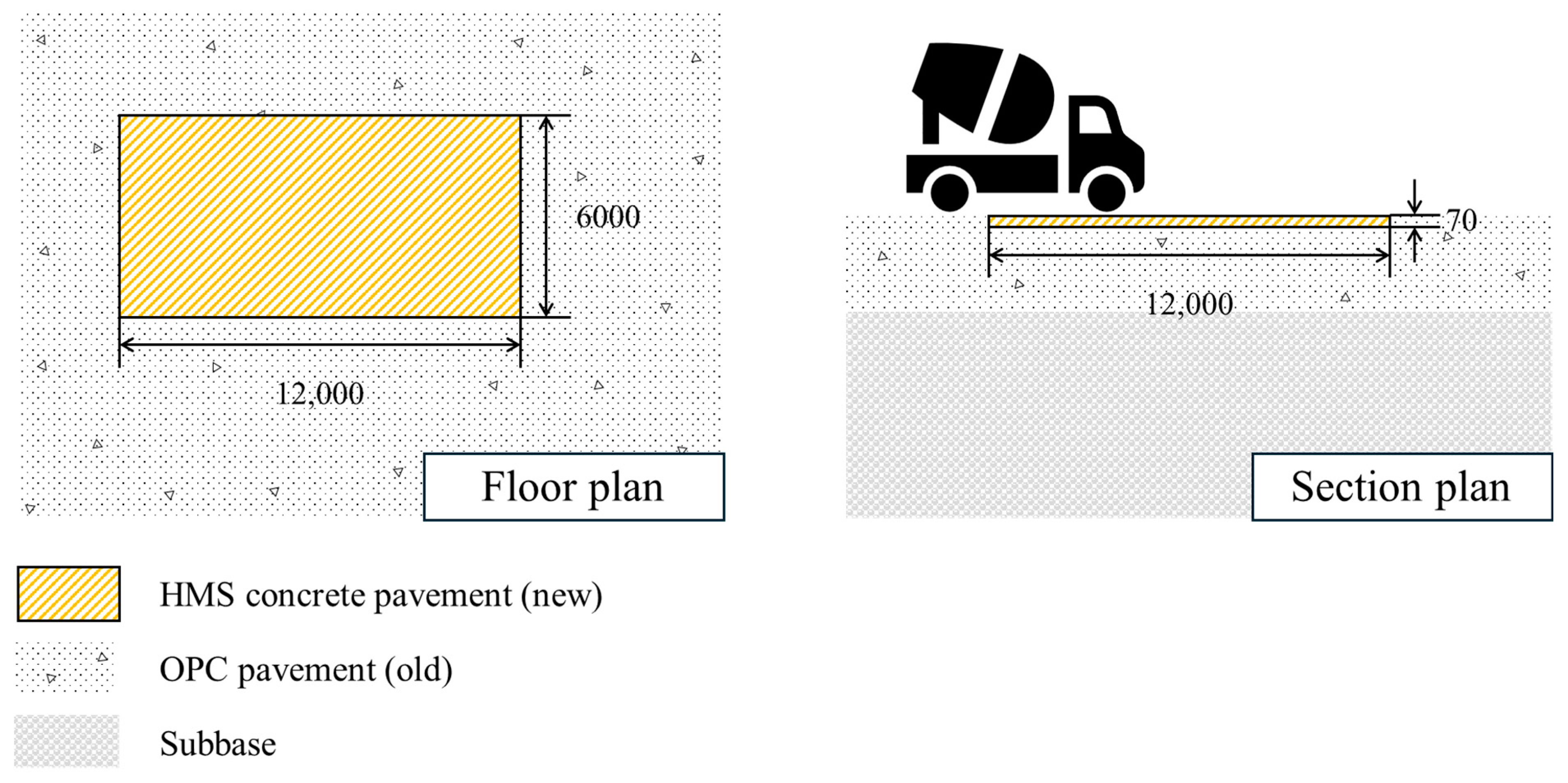
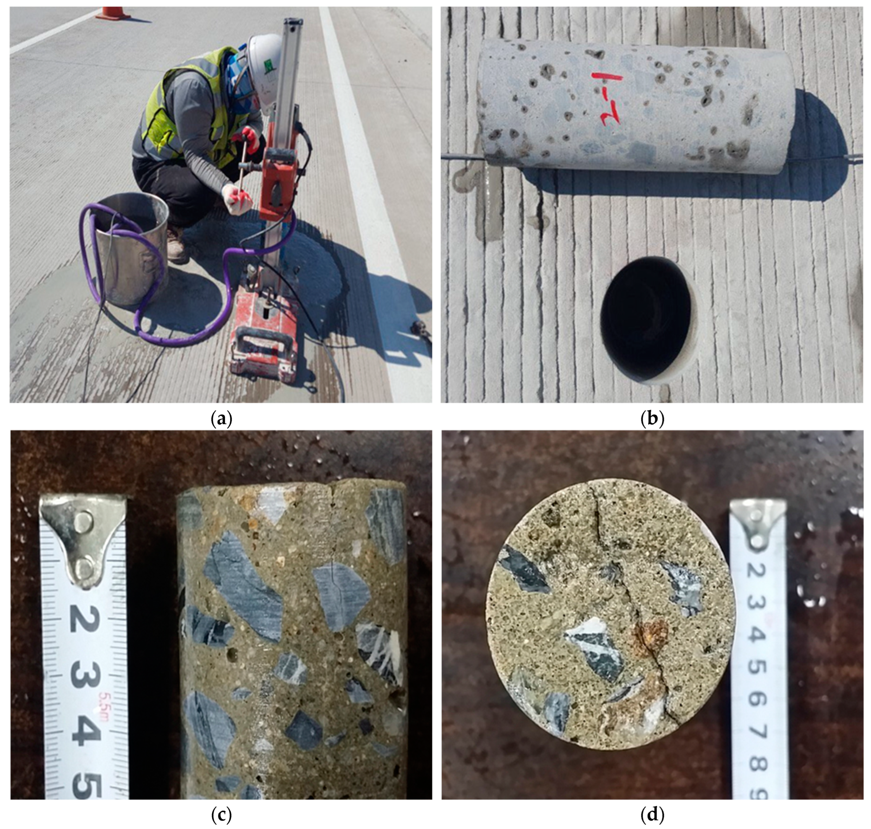
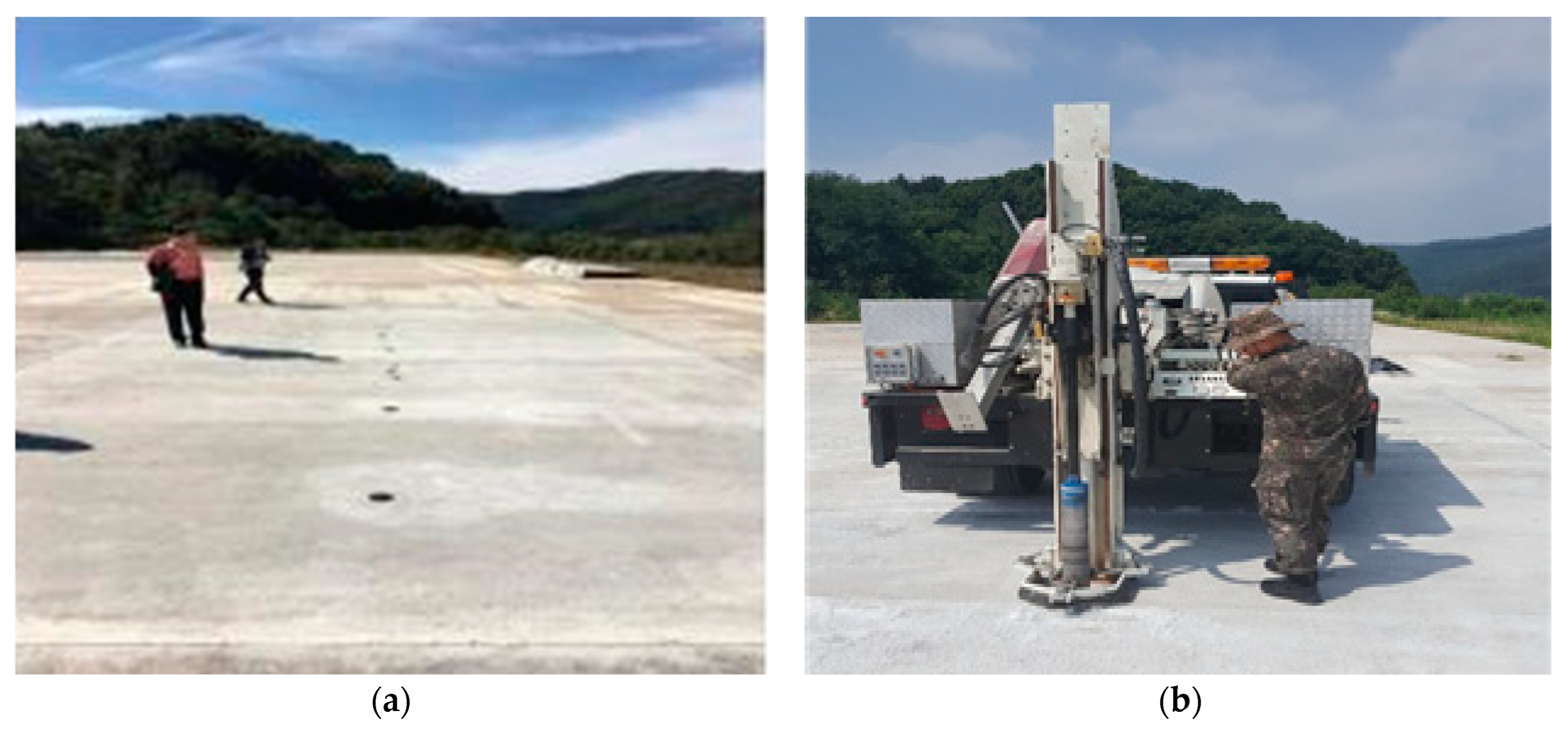
Figure 3 and Table 7 present the site drawings and construction details of the HMS concrete pavement, respectively. On 11 July 2018, HMS concrete was installed on a runway in Chungju, Chungcheongbuk-do, Republic of Korea. The installation was performed on an old concrete pavement with a width of 6000 mm, an extension of 12,000 mm, and a placing thickness of 70 mm. According to the TxDOT research report and the Korean standard specifications for concrete pavements, the maximum size of coarse aggregates should not exceed one-third of the pavement thickness [34,35]. Considering the Korea Expressway Corporation’s research report titled “Study on design and long-term performance evaluation of bonded concrete overlay”, which recommends an overlay thickness of approximately 75 mm based on sensitivity analysis, fatigue behavior analysis, and serviceability evaluation [36], a safety factor of 20% was applied to an overlay pavement thickness of 57 mm. This adjustment, which accounted for a maximum coarse aggregate size of 19 mm, resulted in an approximate thickness of 70 mm. Figure 4 shows a preliminary field study conducted on the Gwangju–Daegu expressway in 2017. During this study, surface cracks were investigated, and core samples were collected to analyze several key factors, including bond strength, abrasion resistance, crack resistance, and crack depth. The results confirmed that a cutting thickness of 70 mm was economical and reasonable, effectively preventing premature damage and ensuring secure bond strength.

3.2. Pavement Application

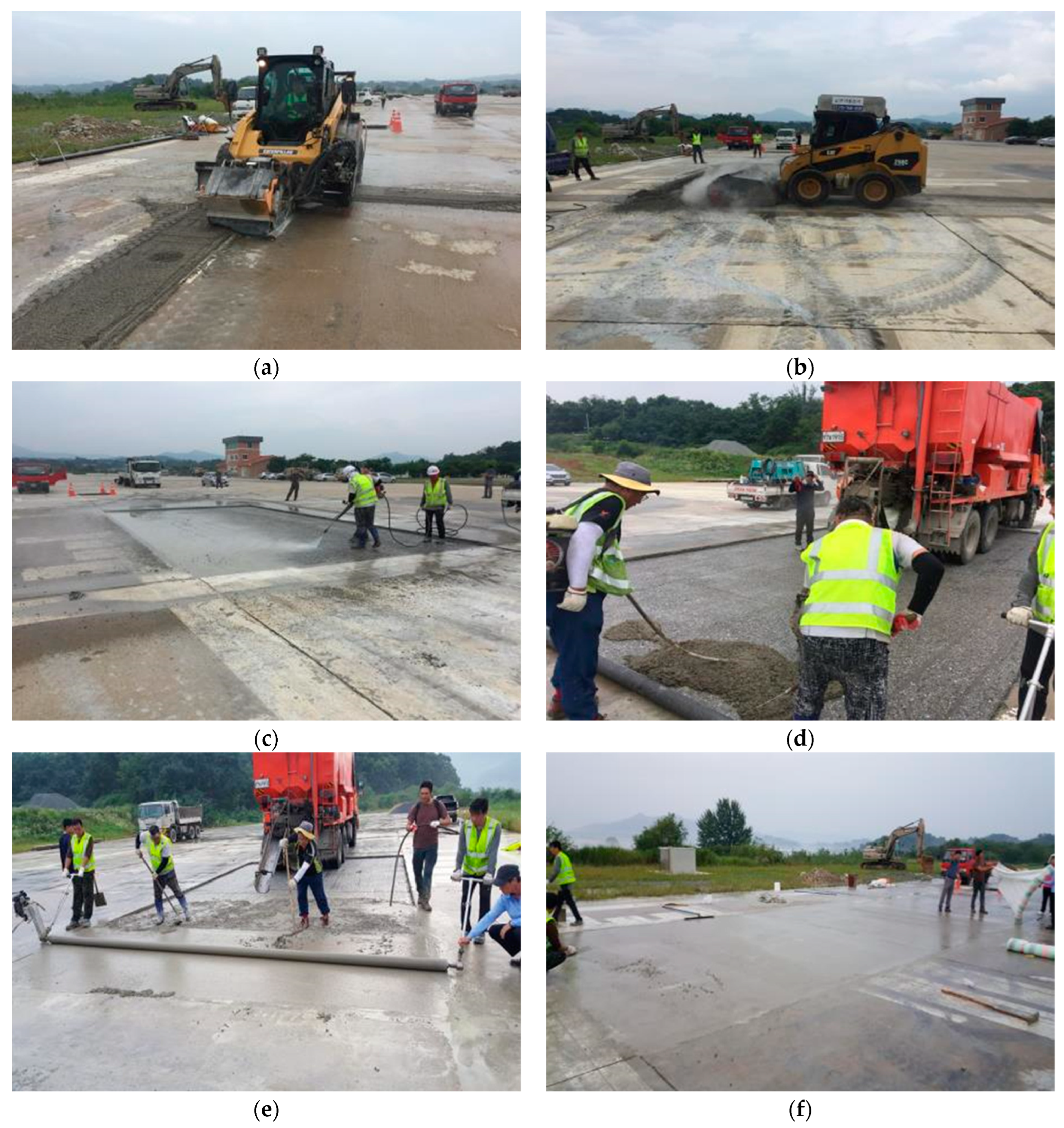
Table 8 lists the field mixture of the HMS concrete pavement. Figure 5 illustrates the procedure for placing the HMS concrete pavement on the runway. In the area shown in Figure 3, the existing conventional concrete pavement was cut to a thickness of 70 mm, debris were removed, surface treatment was performed, and HMS concrete was poured.

3.3. Field Testing

Figure 6 shows a flowchart of the field experiment and evaluation procedure for the construction site. The flowchart includes the basic physical properties, environmental impacts, and post-evaluation.

4. Results and Discussion

4.1. Basic Laboratory Tests

4.1.1. Microstructure Analysis

Figure 7 shows the results of the zeta potential test. By measuring the zeta potential of the ionic particles in water, we determined the size of the ions generated during the cement hydration reaction and the hydrophilic concentration at the HMS interface. Both the cement and HMS exhibited a negative charge. After replacing the HMS and passing it through the flow cell, the cement became negatively charged due to the hydration reaction. Initially, the negative charge increased rapidly, but once a gel formed on the cement surface, it stabilized at a consistent level. Meanwhile, the HMS particles moved and collided with the cement particles, causing friction and gradually generating positive charges. These positive charges reacted with the negative charges in the gel within the cement grains, leading to stabilization and an agglomeration effect. As shown in Figure 7a, the addition of the HMS increased the zeta potential by more than +7 mV, indicating a shift toward a more positive charge with the replacement of the HMS. Figure 7b shows the current measured as a function of the amount of HMS added. The cement exhibited a negative charge of −1.14 mA. Despite the typical positive charge associated with the HMS additive, which was bound to an organic polymer, in the case of HMS, some pyridine and S reacted, and S-N exhibited an anion. Consequently, the HMS polymer exhibited a negative charge of −0.39 mA despite exhibiting a positive current. Figure 7c shows the measured conductivity as a function of the amount of HMS added. Negative charges occurred on the cement particles, and as hydration progressed, the static charge decreased, leading to the agglomeration of hydrates. The polysulfur-DCPD polymer contributed to lowering the zeta potential, resulting in electrostatic repulsion of HMS, while the side chain S-N acted as a dispersant, effectively dispersing the cement particles. Consequently, ions diffused, and the migration speed decreased with increasing HMS content. Figure 7d shows the zeta potential measurements of the upper and lower plates of the flow cell based on the amount of HMS added. In the upper mobile phase, the HMS polymer adsorbed onto the cement, effectively separating the cement particles through electrostatic repulsion, resulting in distinct particles with zeta potential surface charges. The adsorption zeta potential of the mixture decreased, eventually resulting in the same negative charge on the cement particles. Notably, the positive charge values were high when the amount of HMS polymer added was low and decreased linearly as the amount of HMS polymer increased.
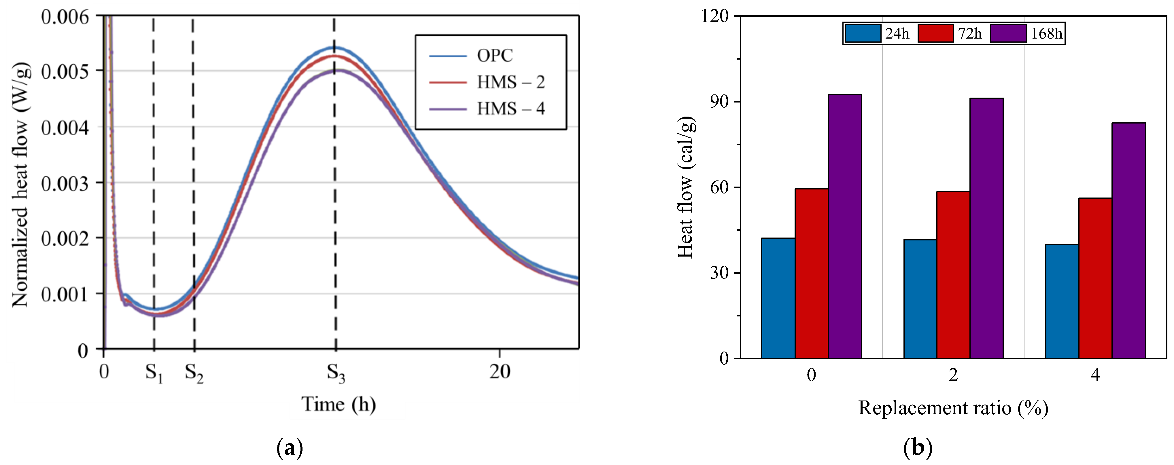
Figure 8 shows the normalized heat flow and heat liberation. In the case of cement paste, an extremely early exothermic peak emerged due to the activity of C3A. Subsequently, S1 (the induction period), exhibited minimal changes in the heat flow. During S2 (the acceleration period), C3S dissolved, leading to the formation and precipitation of major hydrates via the hydration of silicates, which increased the generation of heat liberation. In S3 (the deceleration period), C3A—whose reaction was initially suppressed by the formation of ettringite—rehydrated, resulting in another peak [37,38]. The heat liberation of the cement paste was initially 42.2 cal/g after 24 h. When 2% HMS was substituted, the heat liberation decreased by 1.4%, with a 1.5% change observed after 72 h. A 4% HMS replacement resulted in a 5.4% reduction in heat liberation after 72 h. After 168 h, 2% HMS replacement exhibited a 1.4% decrease in heat liberation, while a 4% replacement resulted in a 10.8% reduction in heat liberation. This suggests that for low ratios of HMS replacement, the decrease in heat of hydration is compensated to some extent by the dilution effect [39,40]. However, above a certain replacement ratio, the heat of hydration was significantly reduced due to the adsorption of HMS on the C3S surface, which prevented further hydration and/or hinders the growth of the gel into crystals, consistent with the findings described in Zheng et al. (2023) [18].
Figure 9 shows the SEM morphology of the cement paste with added HMS. The cement paste reacted with water to form a gel that solidifies over time. The crystal structure of CaCO3 was affected by the ionic substances dissolved in the aqueous solution during solidification, causing variations in crystal growth depending on these ionic components [41]. As shown in the XRD results in Figures S1 and S2 of the Supplementary Materials, the two anhydrous polymorphs of CaCO3, calcite and aragonite, were mixed. The calcite major peak of the cement paste with a 25% HMS replacement ratio was somewhat reduced compared to that with a 5% HMS replacement ratio, which is believed to be due to the ionic reaction of HMS. As the anion content increased, a higher concentration of anions surrounded the cement particles, necessitating cationic materials for flocculation. The cationic content caused portlandite (Ca(OH2)) to develop into a rod-shaped structure, which reacted with atmospheric CO2 to be converted into CaCO3. This hexagonal rhombohedral calcite filled the voids in cement paste, thereby enhancing its strength [42]. At a 25% HMS replacement ratio, the rod-shaped structure aggregated into large rhombohedral shapes, and the crystal structure of CaCO3 grew. It is posited that the ionic particles of HMS promoted the growth and formation of CaCO3 within the gelled cement during hydration. This process enhanced the compressive and flexural strengths and increases the modulus of elasticity by functioning as a nano-fiber composite. CaCO3 functioned as a nanocomposite material, suppressing micro-cracks in concrete and compensating for issues by reacting with CO2, O2, and H2O in the air, thus reducing the rate of weathering and mitigating the depth of carbonation. The growth of the CaCO3 crystal structures is expected to enhance the mechanical properties of the resulting material. This enhancement occurs through several mechanisms: the reduction of the cement’s void ratio, mitigation of micro-cracks, and decreased coefficient of volume expansion in mass cement. In addition, it also improves toughness and reduces the stress concentration by acting as crystalline CaCO3 reinforcing fibers, depending on the particle size, thereby enhancing the overall mechanical characteristics of the material.

4.1.2. Mechanical Performance

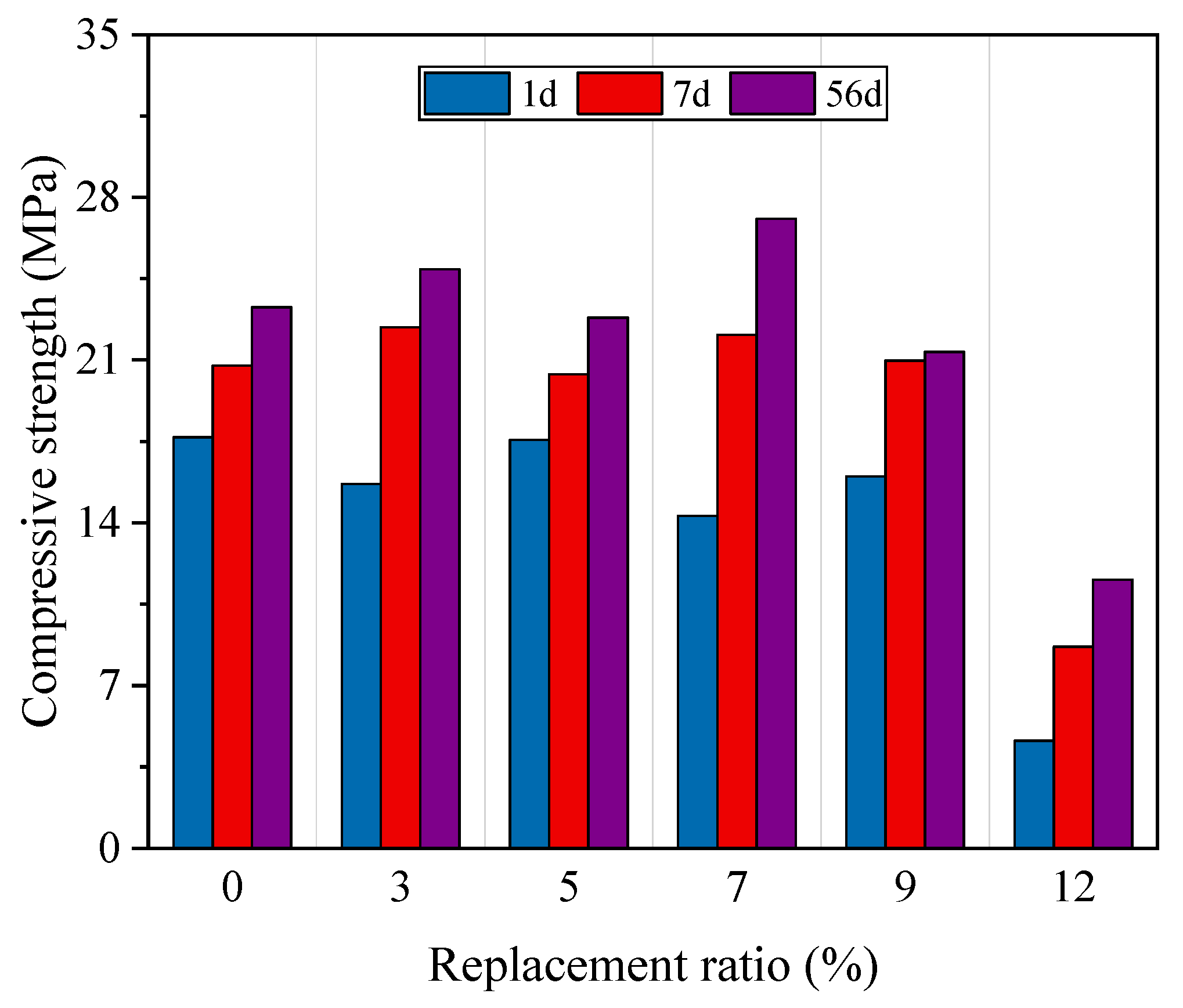
Figure 10 shows the compressive strength at different ages based on the amount of HMS added. For 1-day compressive strength, the addition of 3%, 5%, 7%, 9%, and 12% HMS resulted in 88.7%, 99.4%, 80.9%, 90.5%, and 26.1%, respectively, compared to the OPC. The corresponding values at 7 days were 107.9%, 98.2%, 106.4%, 101.0%, and 41.7%, respectively. For 56-day compressive strength, the values were 107.0%, 98.1%, 116.3%, 91.7%, and 49.6%, respectively. These results indicate that the compressive strength of the HMS-incorporated specimens initially lagged behind that of the OPC. However, the contribution of HMS to the compressive strength enhancement increased over time. Notably, the increase in compressive strength was not proportional to the amount of HMS added. This discrepancy can be attributed to the excessive addition of HMS, which reduced the cement content and consequently impeded strength development, thus offsetting the strength enhancement effect provided by HMS. In particular, the compressive strength significantly decreased upon addition of 12% HMS. This reduction in strength due to excessive HMS concrete was likely caused by the creation of weak points within the cement matrix by HMS, a trend similar to the findings of [18].
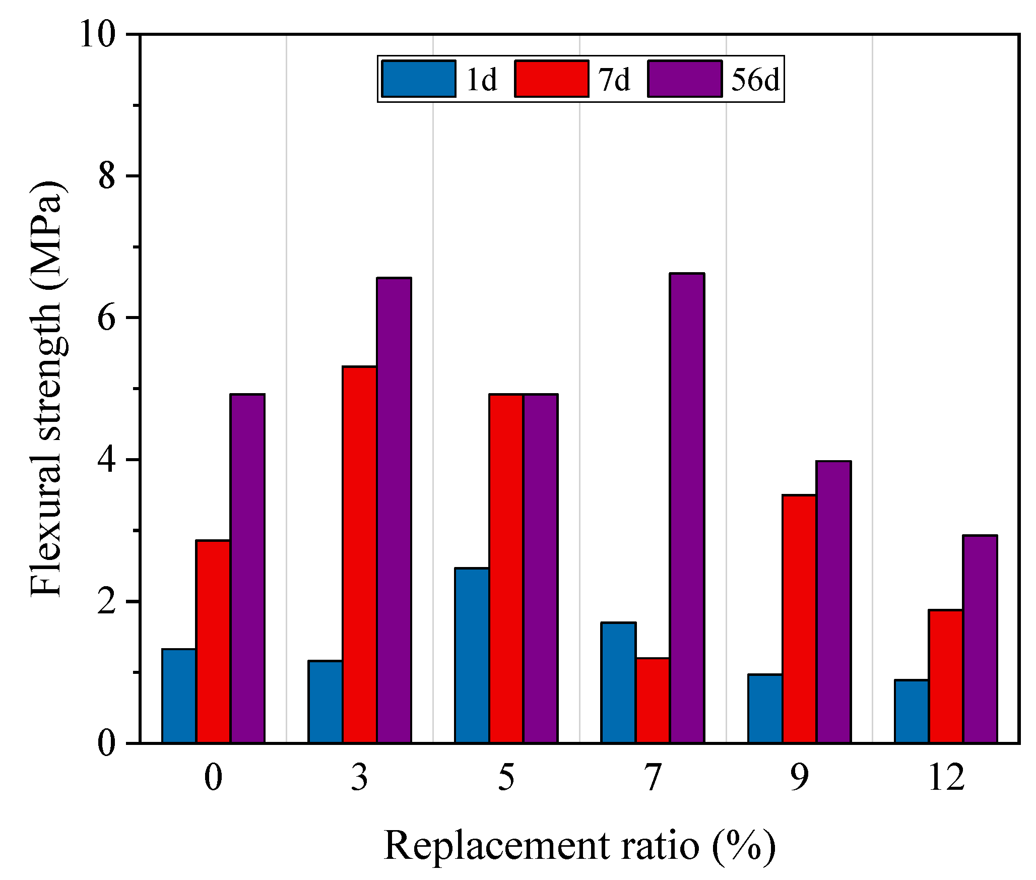
Figure 11 shows the flexural strength at different ages as a function of the HMS addition. For the 1-day flexural strength, the flexural strengths with 3%, 5%, 7%, 9%, and 12% HMS addition were 87.2%, 185.7%, 127.8%, 72.9%, and 66.9%, respectively, compared to the reference OPC. For the 7-day flexural strength, the values were 185.7%, 172.0%, 42.0%, 122.4%, and 65.7%, respectively. For the 56-day flexural strength, the values were 133.3%, 100.0%, 134.8%, 80.9%, and 59.6%, respectively. These results indicate that the effect of HMS addition is more pronounced on the flexural strength than on the compressive strength. As demonstrated in [21], moderate levels of HMS effectively improve flexural strength; however, excessive levels reduce it. Similar to the compressive strength results, the flexural strength significantly decreased upon the addition of 12% HMS. Therefore, considering the results of both the compressive and flexural strength tests, the addition of 3–7% HMS was considered to be the optimal range for enhancing the mechanical performance.

4.1.3. Durability Performance

Figure 12 shows the percentage weight change over time in a sulfuric acid solution. A positive weight change indicates an increase in weight, while a negative weight change indicates a decrease in weight. Mass gain primarily results from cement hydration and swelling caused by water absorption [43]. As the amount of added modified sulfur increased, the weight gain period during immersion increased. In contrast to OPC, which began to lose mass after 7 days of immersion, HMS-12 maintained its pre-immersion mass level for up to 49 days. All specimens exhibited mass loss over time. After 63 days of immersion, the mass losses were 68.3%, 72.3%, 83.9%, 92.2%, 93.3%, and 97.1% for specimens containing 0%, 3%, 5%, 7%, 9%, and 12% HMS, respectively. The mass loss decreased as the HMS content increased. This trend indicates that incorporating HMS contributes to improved chemical resistance.
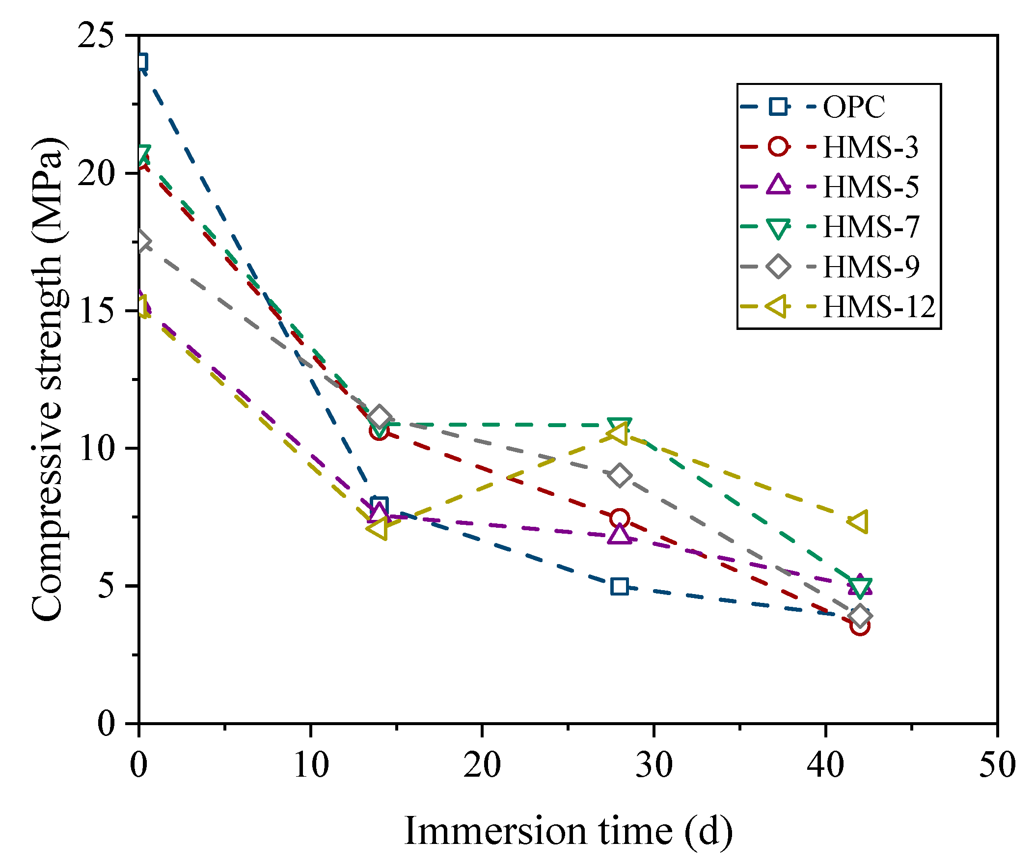
Figure 13 and Figure 14 show the sulfuric acid penetration depth and compressive strength as functions of immersion duration, respectively. As shown in Figure 13, the sulfuric acid penetration depth significantly decreased with the addition of HMS, although the effect was not proportional. At 14 days post-immersion, specimens with 3%, 5%, 7%, 9%, and 12% HMS exhibited penetration depths of 69%, 82%, 67%, 42%, and 70%, respectively, compared to the OPC. At 28 days post-immersion, the results were 74%, 118%, 75%, 90%, and 80%, while at 42 days post-immersion, the results were 80%, 127%, 72%, 95%, and 78%. The HMS effect became visible as early as day 14, although no specific trend was observed over longer periods. As shown in Figure 14, all specimens exhibited reduced compressive strength after immersion. The OPC exhibited the greatest loss at 2 weeks post-immersion, reaching 32.9% of the pre-immersion strength. In contrast, HMS-9 exhibited the least loss in compressive strength, retaining 63.6% of its original strength. At 4 weeks post-immersion, the compressive strength of OPC exhibited the greatest loss at 20.7%, while HMS-12 exhibited the least loss at 69.6%. Similarly, at 6 weeks post-immersion, the compressive strength of the OPC exhibited the greatest loss, declining by 16.0% compared to its pre-immersion value, while the HMS-12 exhibited the least loss at 48.4%. The decrease in compressive strength caused by immersion tended to decrease as the amount of HMS added increased. Considering these findings alongside the results of previous weight changes due to immersion, we conclude that the addition of HMS enhances chemical resistance.
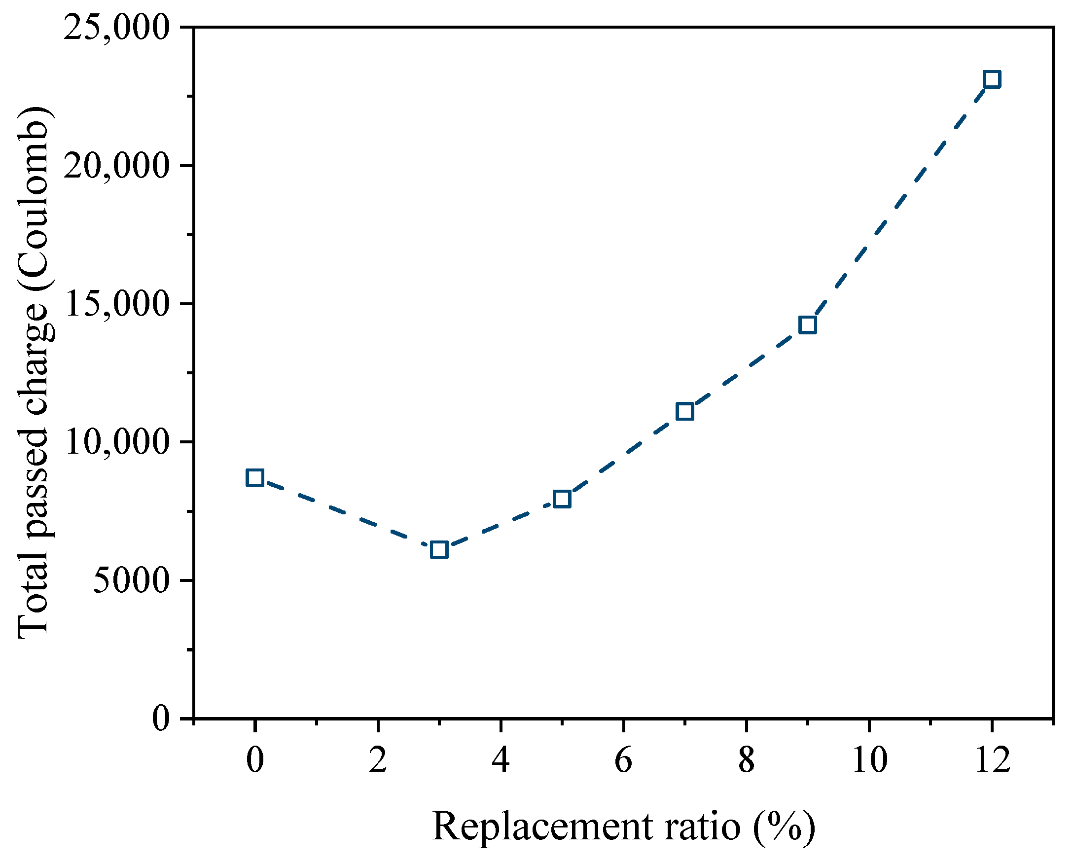
Figure 15 and Figure 16 illustrate the passing charge and chloride-ion penetration depth, respectively, based on the electrical conduction tests conducted on the 78-day-old specimens for each case. As shown in Figure 15, the passing charges of specimens containing 3%, 5%, 7%, 9%, and 12% HMS compared with that of OPC were 70.1%, 91.2%, 127.5%, 163.6%, and 265.5%, respectively. The chloride penetration rate decreased with the addition of up to 5% HMS. However, when the HMS content exceeded 7%, the specimens exhibited increased susceptibility to chloride penetration. As shown in Figure 16, the depths of chloride-ion penetration for the specimens with 3%, 5%, 7%, 9%, and 12% HMS were 62.7%, 113.0%, 108.4%, 149.5%, and 197.8%, respectively, compared to the OPC. Notably, 3% HMS effectively prevented chloride penetration. However, no significant difference was observed between 5% and 7% HMS when compared to the OPC. Beyond 9%, penetration became more pronounced. Based on these experimental results, it was concluded that an HMS content of 3% to 5% is appropriate in terms of chloride penetration.

4.2. Field Testing

Table 9 presents the experimental results obtained from the field tests of the HMS concrete mixture. For field applicability, the air content was 4.0%, and the slump was 145 mm, in accordance with the standard for normal concrete specified in Korean construction guidelines [44]. To evaluate compressive strength, we fabricated a total of Φ100 × 200 mm cylindrical specimens on site. The specimens were then loaded at a constant rate of 0.6 ± 0.4 MPa per second. The compressive strengths of the 7-day-, 28-day-, and 98-day-aged specimens were 30.6, 42.0, and 63.7 MPa, respectively, all meeting the compressive strength requirement of 21 MPa [35] for traffic-opening. In addition, three 100 × 100 × 400 mm rectangular specimens were fabricated on site to evaluate the flexural strength and then loaded at a constant rate of 0.06 ± 0.04 MPa per second. The 28-day flexural strength of 6.0 MPa satisfied the 3.15 MPa traffic-opening criterion [35]. In addition, to evaluate the bond strength, a core with dimensions Φ75 × 80 mm (70 mm of HMS concrete and 10 mm of old conventional concrete for the bottom plate) was drilled, and the failure load was measured under a constant loading stress of 0.035 MPa per second to calculate the bond strength. A total of five tests were performed, and the measured bond strengths were 1.6, 1.6, 1.4, 1.5, and 1.5 MPa, respectively. The average bond strength was 1.5 MPa, which satisfied the traffic-opening criterion of 1.4 MPa [35]. Therefore, the mechanical performance of the HMS concrete was determined to align with the quality criteria for selecting cementitious materials for partial depth repair of road pavements.
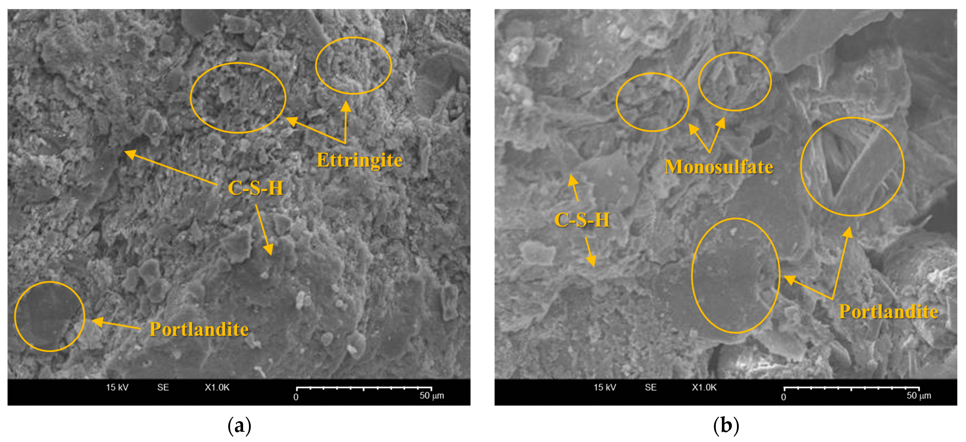
Figure 17 shows SEM images of cores obtained from the site. After 42 days of pouring, the cores were pretreated by breaking them into fine 10 mm fragments and selecting flattened pieces. We employed SEM (SNE-3200M, SEC, Suwon, Republic of Korea) to analyze and compare the microstructures of the HMS and existing pavement sections. Among the cement hydrates, C-S-H gel was present as honeycomb-like fiber masses, while portlandite existed as plate-like crystals approximately 40 μm in size [45,46]. C-S-H and portlandite account for about 75–85% of the volume of all solid phases [45]. In addition, ettringite and monosulfate were present, with crystals as small as a few micrometers, exhibiting needle-like and prismatic structures, respectively [46,47]. As shown in Figure 17a, the microstructure of the HMS concrete fragments closely resembled that of the old conventional concrete fragments shown in Figure 17b, which exhibited a monosulfate structure (prismatic) with few voids. However, the HMS concrete fragments exhibited fine surface bumps, indicating modified ettringite. This structure is believed to increase interparticle bonding, resulting in a denser solidified structure. For further insights into the chemical structure and formation process, future investigations using X-ray diffraction (XRD), X-ray fluorescence (XRF) and energy-dispersive X-ray spectrometer (EDS) analyses are necessary.
Table 9. Properties obtained from field experiments on on-site mixed concrete.
Age (d)Test StandardsAcceptable Quality [35,44]Results
Air content (%)-KS F 2421 [48]3.5–6.54.0
Slump (mm)-KS F 2402 [49]50–150145
Compressive strength (MPa)7KS F 2405 [30]≥2130.6 ± 4.3
Compressive strength (MPa)28KS F 2405 [30]≥2142.0 ± 1.9
Compressive strength (MPa)98KS F 2405 [30]≥2163.7 ± 2.5
Flexural strength (MPa)28KS F 2408 [50]≥3.156.0 ± 0.3
Bond strength (MPa)28KS F 2762 [51]≥1.41.5 ± 0.1
Table 10 lists the test items and results obtained under laboratory conditions for the field HMS concrete mixture. In contrast to the field conditions results shown in Table 9, the 28-day compressive strength under laboratory conditions was 35.5% higher than the 28-day compressive strength of the field specimen due to the stable curing conditions of air curing at 20 ± 1 °C. Notably, the compressive strength reached 45.0 MPa at 3 days, satisfying the traffic-opening criteria of 21 MPa [35]. Similar to the compressive strength, the bond strength under laboratory conditions was also superior to that of the field specimens due to the improved environmental conditions. In particular, the penetration depth after sulfuric acid immersion, changes in the compressive strength after sulfuric acid immersion, and chloride-ion penetration resistance were measured for the OPC concrete to verify its performance through a relative comparison. After 4 weeks of immersion in a 5% sulfuric acid solution, the penetration depths of the OPC concrete were 3.12, 3.35, and 3.15 mm with an average of 3.21 mm, while the penetration depths of the HMS concrete were 1.21, 1.05, and 1.34 mm with an average of 1.20 mm, which was 62.6% less than that of the OPC concrete. For the change in compressive strength after 4 weeks of immersion, the 28-day compressive strength of the OPC concrete decreased by an average of 28.4%, while that of the HMS concrete decreased by only 13.6%. In terms of chloride-ion penetration resistance, the average values of the OPC concrete were 3161 and 2201 coulombs at 7 and 56 days of age, respectively. In contrast, the HMS concrete had average values of 1621 and 937 coulombs at 7 and 56 days of age, respectively, representing decreases of 48.7% and 57.4% compared to the OPC concrete. Notably, the chloride-ion penetration resistance evaluation indices classify as ‘High’ when it was above 4000 coulombs, ‘Moderate’ when it was 2000–4000, ‘Low’ when it was 1000–2000, and ‘Very low’ when it was 100–1000 [52]. The addition of HMS significantly improved chloride-ion penetration resistance.
Figure 18 shows the site monitoring results three months after construction. The site was visually inspected, and cores were taken to check the internal condition of the pavement. No surface efflorescence or delamination of the HMS concrete was observed, and only some micro-cracks were found near the existing concrete cuts and re-pavement areas. In addition, no signs of water leakage were observed in the cracks, nor any delamination or cracking of the re-pavement inside the core. As shown in Table 9 and Table 10, the compressive strength, flexural strength, and bond strength of the on-site mixed HMS concrete exceeded the quality standards required for concrete pavements, indicating that the HMS concrete was able to cope with the loads imposed during service. Furthermore, it is believed that the concrete adequately withstood the effects of environmental changes, including outdoor air and rain.

4.3. Further Field Application Test

Figure 19 shows additional testbeds constructed with HMS concrete pavements. Further field application testing and long-term tracking of the mechanical and durability performances will be conducted to further validate the reliability and performance of HMS concrete pavements for field applications.

5. Conclusions

This study explores the effects of partially replacing cement with HMS on the microstructure, mechanical performance, and durability of cementitious materials. Our objective was to explore HMS as an additive in concrete materials. For field construction, we specifically selected a concrete pavement with the highest potential for the use of HMS concrete. The material properties, environmental impact, and post-application performance were assessed to evaluate its field applicability. The results of this study can be summarized as follows:
  • Cement replacement with HMS altered the zeta potential and significantly reduced the heat liberation during hydration. In addition, SEM analysis confirmed that incorporating HMS positively affected material performance by promoting the agglomeration of rods into large rhombohedral shapes and enhancing the growth of the calcite crystal structure.
  • The incorporation of HMS increased the compressive and flexural strengths. However, the mechanical performance decreased rapidly at a replacement ratio of 12%. In terms of durability, HMS was positively correlated with chemical resistance, but the chloride penetration test revealed increased vulnerability as the replacement ratio exceeded 9%. Our results indicate that maintaining an HMS cement replacement ratio of up to 9% ensures stable performance.
  • A field study was conducted at a runway site in Chungju, Chungcheongbuk-do, Republic of Korea. The existing concrete pavement (6000 × 12,000 × 70 mm W × L × T) was removed, and HMS concrete was used for repaving. Under field conditions, the air content, slump, compressive strength, flexural strength, and bond strength met the quality criteria specified in Korean construction standards. After 3 months of monitoring, no significant abnormalities were observed.
  • After evaluating the mechanical and durability properties of the field HMS concrete mixture, it was determined that all the quality criteria and evaluation indicators met acceptable standards. The comparative analysis between OPC and HMS concrete regarding sulfuric acid immersion penetration depth, compressive strength changes after sulfuric acid immersion, and chloride-ion penetration resistance revealed that HMS concrete outperformed OPC.
Despite its limitations, which include the absence of chemical quantitative analysis of the microstructure using XRD, XRF, and EDS and field verification cases, this study contributes to the industrial application of HMS by comprehensively reviewing the basic properties analysis, implementing the findings in an actual field, evaluating the field applicability according to current construction standards, and monitoring the results over three months. The enhanced mechanical and durability properties of HMS identified in this study suggest that HMS could be increasingly applied to sites requiring high functionality, such as nuclear power plant structures or coastal/marine structures. In addition, the construction of additional testbeds will allow us to address the gaps identified in this study in a series of future studies. In particular, microstructural analysis of the performance improvement mechanisms and lifecycle analysis of long-term performance will provide industrial benefits and increase confidence in the utilization of HMS.

Supplementary Materials

The following supporting information can be downloaded at: https://www.mdpi.com/article/10.3390/buildings14072231/s1, Figure S1: XRD results of the cement paste with a 25% HMS replacement ratio; Figure S2: XRD results of the cement paste with (a) 5% HMS replacement ratio and (b) 25% HMS replacement ratio under the same conditions.

Author Contributions

Conceptualization, S.O.; methodology, S.O. and S.C.; software, S.O.; validation, S.O. and S.C.; formal analysis, S.O. and S.C.; investigation, S.O.; resources, S.C.; data curation, S.O.; writing—original draft preparation, S.O.; writing—review and editing, S.O. and S.C.; visualization, S.O.; supervision, S.C.; project administration, S.C.; funding acquisition, S.C. All authors have read and agreed to the published version of the manuscript.

Funding

This work was supported by the Green Venture Program (S3104982) funded by the Ministry of SMEs and Startups (MSS, Korea). This work was also conducted with the support of the “National R&D Project for Smart Construction Technology (RS-2020-KA156007)” funded by the Korea Agency for Infrastructure Technology Advancement under the Ministry of Land, Infrastructure and Transport, and managed by the Korea Expressway Corporation.

Data Availability Statement

Data will be made available on request.

Conflicts of Interest

The authors declare that they have no known competing financial interests or personal relationships that could have appeared to influence the work reported in this paper.

References

  1. Worrell, E.; Reuter, M.A. Handbook of Recycling: State-of-the-Art for Practitioners, Analysts, and Scientists; Elsevier: Waltham, MA, USA, 2014. [Google Scholar]
  2. Ramachandra, T.; Shruthi, B. Spatial mapping of renewable energy potential. Renew. Sustain. Energy Rev. 2007, 11, 1460–1480. [Google Scholar] [CrossRef]
  3. Sharma, P.; Gaur, V.K.; Gupta, S.; Varjani, S.; Pandey, A.; Gnansounou, E.; You, S.; Ngo, H.H.; Wong, J.W. Trends in mitigation of industrial waste: Global health hazards, environmental implications and waste derived economy for environmental sustainability. Sci. Total Environ. 2022, 811, 152357. [Google Scholar] [CrossRef] [PubMed]
  4. Tavakoli, D.; Hashempour, M.; Heidari, A. Use of waste materials in concrete: A review. Pertanika J. Sci. Technol. 2018, 26, 499–522. [Google Scholar]
  5. Kanamarlapudi, L.; Jonalagadda, K.B.; Jagarapu, D.C.K.; Eluru, A. Different mineral admixtures in concrete: A review. SN Appl. Sci. 2020, 2, 760. [Google Scholar] [CrossRef]
  6. Chalee, W.; Sasakul, T.; Suwanmaneechot, P.; Jaturapitakkul, C. Utilization of rice husk–bark ash to improve the corrosion resistance of concrete under 5-year exposure in a marine environment. Cem. Concr. Compos. 2013, 37, 47–53. [Google Scholar] [CrossRef]
  7. Kim, B.-J.; Yi, C. Experimental study on the shrinkage properties and cracking potential of high strength concrete containing industrial by-products for nuclear power plant concrete. Nucl. Eng. Technol. 2017, 49, 224–233. [Google Scholar] [CrossRef]
  8. Mohamed, A.-M.O.; El-Gamal, M. Sulfur Concrete for the Construction Industry: A Sustainable Development Approach; J. Ross Publishing: Plantation, FL, USA, 2010. [Google Scholar]
  9. Gwon, S.; Ahn, E.; Shin, M. Self-healing of modified sulfur composites with calcium sulfoaluminate cement and superabsorbent polymer. Compos. Part B Eng. 2019, 162, 469–483. [Google Scholar] [CrossRef]
  10. Gulzar, M.A.; Rahim, A.; Ali, B.; Khan, A.H. An investigation on recycling potential of sulfur concrete. J. Build. Eng. 2021, 38, 102175. [Google Scholar] [CrossRef]
  11. Amanova, N.; Turaev, K.; Shadhar, M.H.; Tadjixodjayeva, U.; Jumaeva, Z.; Berdimurodov, E.; Eliboev, I.; Hosseini-Bandegharaei, A. Sulfur-based concrete: Modifications, advancements, and future prospects. Constr. Build. Mater. 2024, 435, 136765. [Google Scholar] [CrossRef]
  12. Shin, M.; Kim, K.; Gwon, S.-W.; Cha, S. Durability of sustainable sulfur concrete with fly ash and recycled aggregate against chemical and weathering environments. Constr. Build. Mater. 2014, 69, 167–176. [Google Scholar] [CrossRef]
  13. Rasheed, Q.; Sikandar, M.A.; Khan, M.H.; Akash, K.; Nasir, H.; Khan, B.J. Assessment of chloride-induced reinforcement corrosion protection of modified sulfur polymer composites. Constr. Build. Mater. 2021, 268, 121086. [Google Scholar] [CrossRef]
  14. Gwon, S.; Ahn, E.; Shin, M. Water permeability and rapid self-healing of sustainable sulfur composites using superabsorbent polymer and binary cement. Constr. Build. Mater. 2020, 265, 120306. [Google Scholar] [CrossRef]
  15. Dugarte, M.; Martinez-Arguelles, G.; Torres, J. Experimental evaluation of modified sulfur concrete for achieving sustainability in industry applications. Sustainability 2018, 11, 70. [Google Scholar] [CrossRef]
  16. El Gamal, M.M.; El-Dieb, A.S.; Mohamed, A.-M.O.; El Sawy, K.M. Performance of modified sulfur concrete exposed to actual sewerage environment with variable temperature, humidity and gases. J. Build. Eng. 2017, 11, 1–8. [Google Scholar] [CrossRef]
  17. Park, S.-B.; Kim, S.-C.; Kim, K.-H.; Hong, C.-H. Experimental study on development of artificial fishing reefs using environment-friendly sulfur concrete. J. Ocean Eng. Technol. 2007, 21, 58–64. [Google Scholar]
  18. Zheng, S.; Lu, X.; Zhao, J.; He, R.; Chen, H.; Geng, Y. Influence of industrial by-product sulfur powder on properties of cement-based composites for sustainable infrastructures. Constr. Build. Mater. 2023, 367, 130171. [Google Scholar] [CrossRef]
  19. Na, O.-J. A Study on the Mechanical Properties and Durability for the Concrete Using Modified Sulfur Mixture Liquid and Powder. Master’s Thesis, Sangmyung University, Seoul, Republic of Korea, 2014. [Google Scholar]
  20. Lee, J.-N.; Choe, M.-S.; Park, Y.-K.; Choe, K.-T.; Kim, C.-H. A Study on the Physicochemical Properties of Cement Concrete with Addition of Hydraulic Modified Sulfur That Can Be Used at Room Temperature; The Korean Society of Manufacturing Technology Engineers: Gangneung, Republic of Korea, 2022; p. 232. [Google Scholar]
  21. Lee, S.-H.; Hong, K.-N.; Park, J.-K.; Ko, J. Influence of aggregate coated with modified sulfur on the properties of cement concrete. Materials 2014, 7, 4739–4754. [Google Scholar] [CrossRef]
  22. Jung, W.K. Evaluation of Physical Properties of Concrete Using the Powder Type Low-Melting-Temperature Modified Sulfur. In Proceedings of the Korea Concrete Institute, Changwon, Republic of Korea, 2–4 May 2018; Volume 30, pp. 599–600. [Google Scholar]
  23. Huang, H.; Yuan, Y.; Zhang, W.; Zhu, L. Property assessment of high-performance concrete containing three types of fibers. Int. J. Concr. Struct. Mater. 2021, 15, 39. [Google Scholar] [CrossRef]
  24. Li, Z.; Gao, M.; Lei, Z.; Tong, L.; Sun, J.; Wang, Y.; Wang, X.; Jiang, X. Ternary cementless composite based on red mud, ultra-fine fly ash, and GGBS: Synergistic utilization and geopolymerization mechanism. Case Stud. Constr. Mater. 2023, 19, e02410. [Google Scholar] [CrossRef]
  25. KS F 2504; Standard Test Method for Density and Water Absorption Rate of Fine Aggregates. Korean Standards Association: Seoul, Republic of Korea, 2020.
  26. KS F 2503; Standard Test Method for Density and Water Absorption of Coarse Aggregates. Korean Standards Association: Seoul, Republic of Korea, 2019.
  27. KS F 2502; Standard Test Method for Sieve Analysis of Aggregates. Korean Standards Association: Seoul, Republic of Korea, 2019.
  28. KS F 4042; Polymer Modified Cement Mortar for Maintenance in Concrete Structure. Korean Standards Association: Seoul, Republic of Korea, 2012.
  29. ASTM C267; Standard Test Methods for Chemical Resistance of Mortars, Grouts, and Monolithic Surfacings and Polymer Concretes. American Society for Testing and Materials (ASTM) International: West Conshohocken, PA, USA, 2020.
  30. KS F 2405; Test Method for Compressive Strength of Concrete. Korean Standards Association: Seoul, Republic of Korea, 2022.
  31. KS F 2596; Standard Test Method for Measuring Carbonation Depth of Concrete. Korean Standards Association: Seoul, Republic of Korea, 2019.
  32. KS F 2711; Standard Test Method for Resistance of Concrete to Chloride Ion Penetration by Electrical Conductance. Korean Standards Association: Seoul, Republic of Korea, 2017.
  33. KS F 2737; Standard Test Method for Penetration Depth of Chloride Ion in Concrete by Using Indicator. Korean Standards Association: Seoul, Republic of Korea, 2021.
  34. McCullough, B.F.; Fowler, D.W. Bonded Concrete Overlay (BCO) Project Selection, Design, and Construction; Center for Transportation Research, University of Texas: Austin, TX, USA, 1994. [Google Scholar]
  35. Korea Road Association, Bonded Concrete Overlay (KCS 44 99 10), Korean Construction Specification (KCS), Ministry of Land, Infrastructure and Transport (MOLIT), Seoul, Republic of Korea. 2023. Available online: https://kcsc.re.kr/StandardCode/Viewer/426 (accessed on 16 June 2024). (In Korean).
  36. Korea Expressway Corporation. Study on the Design and Long-Term Performance Evaluation of Bonded Concrete Overlay; Korea Expressway Corporation: Gimcheon, Gyeongsangbuk-do, Republic of Korea, 2013. [Google Scholar]
  37. Marchon, D.; Flatt, R.J. Mechanisms of cement hydration. In Science and Technology of Concrete Admixtures; Elsevier: Amsterdam, The Netherlands, 2016; pp. 129–145. [Google Scholar]
  38. Mehta, P.K.; Monteiro, P. Concrete: Microstructure, Properties, and Materials, 3rd ed.; McGraw-Hill: New York, NY, USA, 2006. [Google Scholar]
  39. Escalante-Garcıa, J.; Sharp, J. Effect of temperature on the hydration of the main clinker phases in Portland cements: Part II, blended cements. Cem. Concr. Res. 1998, 28, 1259–1274. [Google Scholar] [CrossRef]
  40. Oh, S.; Kim, J.; Song, C.; Choi, S. Effects of fineness and substitution rate of GGBFS on material characteristics of GGBFS-blended cement mortars: Hydration, non-evaporable water, pore structure, mechanical properties, self-desiccation, and autogenous shrinkage. J. Build. Eng. 2024, 92, 109741. [Google Scholar] [CrossRef]
  41. Ramakrishna, C.; Thenepalli, T.; Ahn, J.W. A brief review of aragonite precipitated calcium carbonate (PCC) synthesis methods and its applications. Korean Chem. Eng. Res. 2017, 55, 443–455. [Google Scholar]
  42. Stepkowska, E.T. Hypothetical transformation of Ca(OH)2 into CaCO3 in solid-state reactions of portland cement. J. Therm. Anal. Calorim. 2005, 80, 727–733. [Google Scholar] [CrossRef]
  43. Sajid, H.U.; Kiran, R.; Bajwa, D.S. Effect of agro-derived corrosion inhibitors on the properties of Portland cement mortar. Constr. Build. Mater. 2021, 310, 125236. [Google Scholar] [CrossRef]
  44. Korea Concrete Institute (KCI), Normal Concrete (KCS 14 20 10), Korean Construction Specification (KCS), Ministry of Land, Infrastructure and Transport (MOLIT), Seoul, Republic of Korea. 2022. Available online: https://kcsc.re.kr/StandardCode/Viewer/426 (accessed on 16 June 2024). (In Korean).
  45. Franus, W.; Panek, R.; Wdowin, M. SEM investigation of microstructures in hydration products of portland cement. In Proceedings of the 2nd International Multidisciplinary Microscopy and Microanalysis Congress: Proceedings of InterM, Mugla, Turkey, 16–19 October 2014; pp. 105–112.
  46. Baur, I.; Keller, P.; Mavrocordatos, D.; Wehrli, B.; Johnson, C.A. Dissolution-precipitation behaviour of ettringite, monosulfate, and calcium silicate hydrate. Cem. Concr. Res. 2004, 34, 341–348. [Google Scholar] [CrossRef]
  47. Telesca, A.; Marroccoli, M.; Pace, M.L.; Tomasulo, M.; Valenti, G.L.; Monteiro, P. A hydration study of various calcium sulfoaluminate cements. Cem. Concr. Compos. 2014, 53, 224–232. [Google Scholar] [CrossRef]
  48. KS F 2421; Standard Test Method for Air Content of Fresh Concrete by the Pressure Method (Air Receiver Method). Korean Standards Association: Seoul, Republic of Korea, 2016.
  49. KS F 2402; Test Method for Concrete Slump. Korean Standards Association: Seoul, Republic of Korea, 2022.
  50. KS F 2408; Standard Test Method for Flexural Strength of Concrete. Korean Standards Association: Seoul, Republic of Korea, 2016.
  51. KS F 2762; Standard Test Method for the Bond Strength of Concrete Repair and Overlay Materials by Pull-Off Method. Korean Standards Association: Seoul, Republic of Korea, 2016.
  52. ASTM C1202; Standard Test Method for Electrical Indication of Concrete’s Ability to Resist Chloride Ion Penetration. American Society for Testing and Materials (ASTM) International: West Conshohocken, PA, USA, 2022.
  53. KS F 2438; Standard Test Method for Static Modulus of Elasticity and Poisson’s Ratio in Compression of Cylindrical Concrete Specimens. Korean Standards Association: Seoul, Republic of Korea, 2017.
  54. KS F 2424; Standard Test Method for Length Change of Mortar and Concrete. Korean Standards Association: Seoul, Republic of Korea, 2020.
  55. KS F 2609; Standard Test Method for the Water Absorption Coefficient of Building Materials. Korean Standards Association: Seoul, Republic of Korea, 2023.
  56. ASTM C779/C779M; Standard Test Methods for Abrasion Resistance of Horizontal Concrete Surfaces. American Society for Testing and Materials (ASTM) International: West Conshohocken, PA, USA, 2019.
  57. KS F 2456; Test Method for Resistance of Concrete to Rapid Freezing and Thawing. Korean Standards Association: Seoul, Republic of Korea, 2013.
  58. KS F 2715; Standard Test Method for Water-Soluble Chloride in Mortar and Concrete. Korean Standards Association: Seoul, Republic of Korea, 2017.
  59. AASHTO T336; Standard Method of Test for Coefficient of Thermal Expansion of Hydraulic Cement Concrete. American Association of State Highway and Transportation Officials (AASHTO): Washington, DC, USA, 2022.
  60. SS 13 72 44; Concrete Testing—Hardened Concrete—Scaling at Freezing. Swedish Institute for Standards (SIS): Stockholm, Sweden, 2005.
  61. AASHTO PP 34-99; Standard Practice for Estimating the Cracking Tendency of Concrete. American Association of State Highway and Transportation Officials (AASHTO): Washington, DC, USA, 2005.
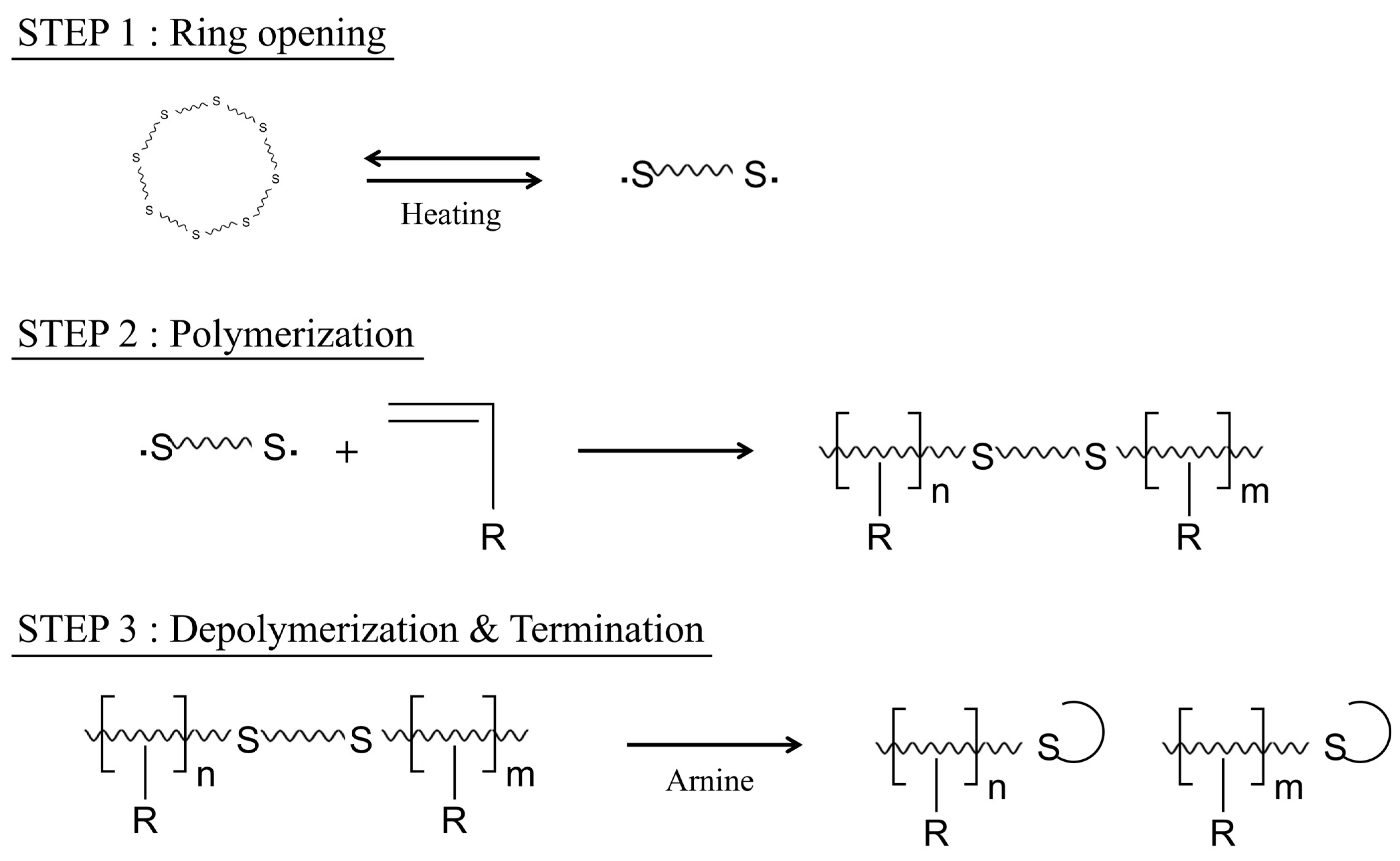
Figure 1. HMS powder synthesis mechanism.
Buildings 14 02231 g001
Figure 2. Sulfur’s crystal structure and crystalline state dependent on temperature.
Buildings 14 02231 g002
Figure 3. Execution scheme drawing of the field study (unit: mm).
Buildings 14 02231 g003
Figure 4. Preliminary field study (2017) on the Gwangju–Daegu expressway, Republic of Korea. (a) Coring operation at the site, (b) core sample, (c) crack depth, and (d) surface crack of the core sample.
Buildings 14 02231 g004
Figure 5. (a) Removal of old concrete pavement, (b) cleaning, (c) surface treatment, (d) casting of HMS concrete pavement, (e) finishing, and (f) curing.
Buildings 14 02231 g005
Figure 6. Flowchart of the HMS concrete pavement application field study.
Buildings 14 02231 g006
Figure 7. Test results of the zeta potential analysis. (a) Zeta potential, (b) current, (c) conductivity, and (d) zeta potential at the upper surface and lower surface of the flow cell.
Buildings 14 02231 g007
Figure 8. Test results of isothermal calorimetry. (a) Normalized heat flow and (b) heat liberation.
Buildings 14 02231 g008
Figure 9. SEM morphology of the cement paste replaced by (a) 5% HMS and (b) 25% HMS.
Buildings 14 02231 g009
Figure 10. Test results of compressive strength at various replacement ratio of HMS.
Buildings 14 02231 g010
Figure 11. Test results of the flexural strength at various replacement ratio of HMS.
Buildings 14 02231 g011
Figure 12. Mass change of each specimen after immersion.
Buildings 14 02231 g012
Figure 13. Penetration depth of each specimen after immersion.
Buildings 14 02231 g013
Figure 14. Deterioration of compressive strength for each specimen after immersion.
Buildings 14 02231 g014
Figure 15. Charge passed of each specimen.
Buildings 14 02231 g015
Figure 16. Chloride-ion penetration depth of each specimen.
Buildings 14 02231 g016
Figure 17. SEM morphology of the core samples of (a) HMS concrete and (b) old concrete.
Buildings 14 02231 g017
Figure 18. Results of 3 months of field monitoring. (a) Visual inspection, (b) sample cores, (c) core drilling, and (d) pavement inside testing.
Buildings 14 02231 g018aBuildings 14 02231 g018b
Figure 19. Further field study on the application of HMS concrete pavement. (a) Tancheon bridge, Republic of Korea. (b) Mandeok IC, Republic of Korea.
Buildings 14 02231 g019
Table 1. HMS manufacturing process.
StepAction
1Introduce powdered sulfur into a 500-mL temperature-controlled reactor.
2Melt the sulfur and maintain the temperature at 130 °C.
3Gradually add the DCPD monomer over approximately 30 min while stirring with an impeller.
4Maintain the temperature at 130 °C and allow the reaction to proceed for 60 min.
5When the mixture turns dark red, slowly add pyridine.
6As the color deepens and the mixture becomes viscous, evaporate any unreacted pyridine.
7Cool to room temperature.
Table 2. Chemical compositions of OPC and HMS used in experiment (mass%).
ComponentsOPCHMS
CaO 62.790.094
SiO221.743.11
Al2O3 5.000.74
Fe2O33.170.075
MgO2.970.091
SO31.6725.66
K2O1.360.032
Na2O0.110.041
SrO-0.035
P2O5-0.023
TiO2-0.013
LOI *1.1970.08
* Loss on ignition.
Table 3. Sieve analysis results of aggregates.
Coarse AggregatesFine Aggregates
Sieve Size (mm)Passing Percentage (%)Max (%)Min (%)Sieve Size (mm)Passing Percentage (%)Max (%)Min (%)
2510010010010100100100
20991009059910095
104055202.59110080
5-10-1.2588550
2.5-5-0.6316025
PAN---0.5133010
0.154102
PAN---
Table 4. Mix proportions of specimens in the mechanical performance experiments.
Specimen
ID
Water
(kg/m3)
Cement
(kg/m3)
Limestone
(kg/m3)
HMS
(kg/m3)
Sand
(kg/m3)
Crushed Sand
(kg/m3)
Stone Dust
(kg/m3)
Chemical Admixture
(kg/m3)
OPC5691138284-1051311131778.5
HMS-35691137242431051311131778.5
HMS-55691137213711051311131778.5
HMS-75691137185991051311131778.5
HMS-956911371561281051311131778.5
HMS-1256911371141711051311131778.5
Table 5. Mix proportions of specimens in the experiments for chemical resistance.
Specimen
ID
Water
(kg/m3)
Cement
(kg/m3)
Limestone
(kg/m3)
HMS
(kg/m3)
Sand
(kg/m3)
Crushed Sand
(kg/m3)
Stone Dust
(kg/m3)
Chemical Admixture
(kg/m3)
OPC347694174-641189919395.21
HMS-334769414826641189919395.21
HMS-534769413043641189919395.21
HMS-734769411361641189919395.21
HMS-93476949578641189919395.21
HMS-1234769469104641189919395.21
Table 6. Mix proportions of specimens for chloride-ion penetration resistance experiments.
Specimen
ID
Water
(kg/m3)
Cement
(kg/m3)
Limestone
(kg/m3)
HMS
(kg/m3)
Sand
(kg/m3)
Crushed Sand
(kg/m3)
Stone Dust
(kg/m3)
Chemical Admixture
(kg/m3)
OPC436873218-806238724376.55
HMS-343687218533806238724376.55
HMS-543687216455806238724376.55
HMS-743687214276806238724376.55
HMS-943687212098806238724376.55
HMS-1243687287131806238724376.55
Table 7. Details of dimensions and quantity for the field study.
CaseWidth (m)Length (m)Area (m2)Thickness (mm)Volume (m3)
Test6.012.072.0705.04
Table 8. Mix proportions of HMS concrete pavement for field application.
Water (kg/m3)Cement (kg/m3)HMS (kg/m3)Sand (kg/m3)Gravel (kg/m3)SP 1 (% 2)AE 3 (% 4)
152368329118491.41.0
1 Superplasticizer. 2 By weight of the binder. 3 Air entraining agent. 4 By weight of the superplasticizer.
Table 10. Properties obtained from laboratory experiments on on-site mixed concrete.
Age (d)Test StandardsAcceptable Quality [35,44]Results
Compressive strength (MPa)3KS F 2405 [30]≥2145.0 ± 0.4
Compressive strength (MPa)28KS F 2405 [30]≥2156.9 ± 2.9
Flexural strength (MPa)28KS F 2408 [50]≥3.155.7 ± 0.2
Bond strength (MPa])3KS F 2762 [51]≥1.41.8 ± 0.1
Static modulus of elasticity (MPa)28KS F 2438 [53]11,300–78,00058,376 ± 1.933
Length change (%)14KS F 2424 [54]≤0.150.0309 ± 0.0028
Water absorption coefficient (kg/cm2)28KS F 2609 [55]≤0.180.001161 ± 0.000120
Chemical resistance (%)28ASTM C 267 [29]≥7584.1 ± 4.4
Abrasion resistance (mm)28ASTM C 779—method B [56]≤20.31 ± 0.07
Resistance to freezing and thawing (%)28KS F 2456 [57]≥8098.1 ± 0.3
Resistance to chloride-ion penetration (C)56KS F 2711 [32]≤1000937 ± 8
Chloride content (kg/m3)28KS F 2715 [58]≤0.30.020 ± 0.009
Coefficient of thermal expansion (×10−6/°C)28AASHTO T 336 [59]4–2010.86
Scaling resistance (m56/m28)56SS 13 72 44 [60]<21.93 ± 0.06
Crack resistance (–)56AASHTO PP 34 99 [61]No cracks occurredNo cracks occurred
Disclaimer/Publisher’s Note: The statements, opinions and data contained in all publications are solely those of the individual author(s) and contributor(s) and not of MDPI and/or the editor(s). MDPI and/or the editor(s) disclaim responsibility for any injury to people or property resulting from any ideas, methods, instructions or products referred to in the content.