
Ontology for BIM-Based Robotic Navigation and Inspection Tasks

Abstract
:1. Introduction
2. Literature Review
2.1. Inspection Tasks during the Construction and Operation Phases
2.1.1. Construction Inspection
2.1.2. Inspection during Operation Phase
2.1.3. Post-Disaster Inspection
2.2. Using Robots for Inspection
2.3. IFC-Based Navigation
2.4. Review of Related Ontologies
2.4.1. AEC/FM Ontologies
2.4.2. Ontologies for Robots

| Ontology | Metrics | |||
|---|---|---|---|---|
| Classes | Relations | Attributes | Individuals | |
| BOT v.0.3.2 [9] | 10 | 16 | 1 | 5 |
| FOG v.0.4 [71] | 3 | 14 | 119 | 4 |
| ifcOWL v.4.1 [65] | 1360 | 1644 | 5 | 1171 |
| DOT v.0.8 [10] | 13 | 13 | 3 | 1 |
| MEP v0.1.0 [68] | 484 | 0 | 1 | 1 |
| OMG v.0.3 [70] | 8 | 17 | 2 | 0 |
| BEO v.0.1.0 [67] | 183 | 0 | 1 | 1 |
| OPM v.0.1.0 [69] | 17 | 8 | 4 | 1 |
2.5. Related Works
| Paper | Inspected Elements | Phase | Navigation | Robot | Sensor | BIM | Ontology | |||||
|---|---|---|---|---|---|---|---|---|---|---|---|---|
| UAV | UGV | LiDAR | RGB Camera | Depth Camera | Thermal Camera | Model/IFC | Mismatch Consideration | |||||
| An autonomous thermal scanning system with which to obtain the 3D thermal models of buildings [79] | Indoor building elements | O | ✓ | - | ✓ | ✓ | ✓ | - | ✓ | - | - | - |
| A framework for the automated acquisition and processing of as-built data with autonomous unmanned aerial vehicles [80] | Building elements | C | ✓ | ✓ | - | ✓ | ✓ | ✓ | - | ✓ | ✓ | - |
| The automated robotic monitoring and inspection of steel structures and bridges [81] | Steel cracks | O | ✓ | - | ✓ | ✓ | ✓ | ✓ | - | - | - | - |
| Automatic wall defect detection using an autonomous robot: a focus on data collection [82] | Walls | O | ✓ | - | ✓ | ✓ | - | - | - | - | - | - |
| Autonomous robotic exploration by incremental road map construction [83] | Indoor building elements | O | ✓ | - | ✓ | ✓ | - | - | - | - | - | - |
| Planning and executing construction inspections with unmanned aerial vehicles [84] | Building roofs | C | ✓ | ✓ | - | - | ✓ | - | - | ✓ | - | - |
| Tunnel structural inspection and assessment using an autonomous robotic system [85] | Concrete cracks | O | ✓ | - | ✓ | ✓ | ✓ | ✓ | - | - | - | - |
| The design and development of an inspection robotic system for indoor applications [86] | Building elements (tested on walls) | O | ✓ | - | ✓ | - | ✓ | ✓ | ✓ | - | - | - |
| A semi-autonomous mobile robot for bridge inspection [87] | Concrete cracks (tested on columns) | O | - | - | ✓ | - | ✓ | - | - | - | - | - |
| The IFC-based development of as-built and as-is BIMs using construction and facility inspection data: site-to-BIM data transfer automation [77] | Building elements: walls, doors, outlets, and light fixtures | O | - | - | - | - | ✓ | - | - | ✓ | ✓ | - |
| The automated quality assessment of precast concrete elements with geometry irregularities using terrestrial laser scanning [78] | Precast concrete elements | C | - | - | - | ✓ | - | - | - | ✓ | ✓ | - |
| Infrared building inspection with unmanned aerial vehicles [88] | Building elements (tested on roofs and roof windows) | O | - | ✓ | - | - | - | - | ✓ | - | - | - |
| Efficient search for known objects in unknown environments using autonomous indoor robots [89] | Indoor building elements | O | ✓ | - | ✓ | - | ✓ | ✓ | - | - | - | ✓ |
| A robotic crack inspection and mapping system for bridge deck maintenance [90] | Concrete cracks | O | ✓ | - | ✓ | ✓ | ✓ | - | - | - | - | - |
| Low-cost aerial unit for the outdoor inspection of building façades [91] | Building facade and envelope elements (tested on facade openings) | O | - | ✓ | - | - | ✓ | ✓ | - | - | - | - |
| Auto inspection system using a mobile robot for detecting concrete cracks in a tunnel [92] | Concrete cracks (tested on walls) | O | - | - | ✓ | - | ✓ | - | - | - | - | - |
3. Developing OBRNIT
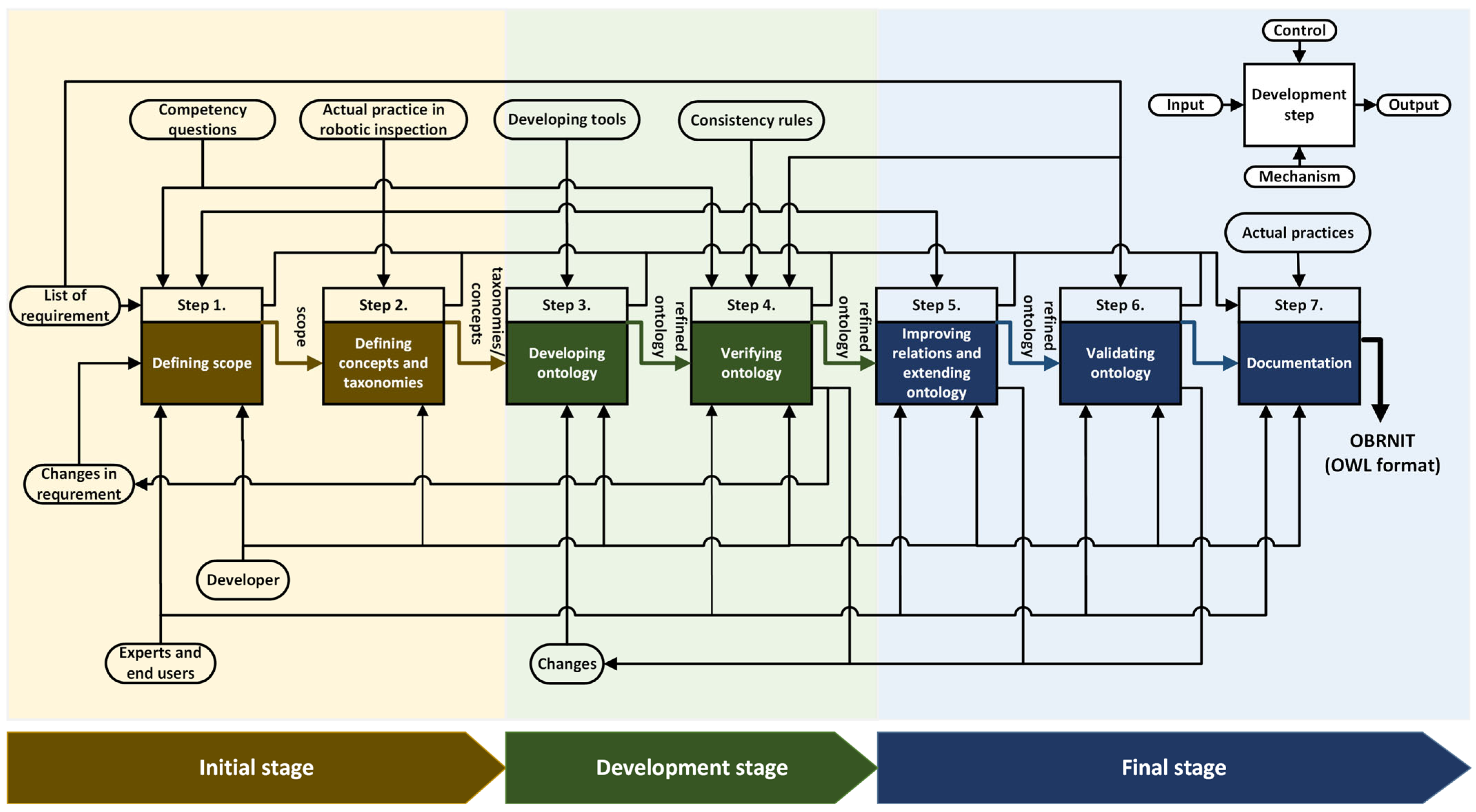
3.1. Methodology Workflow
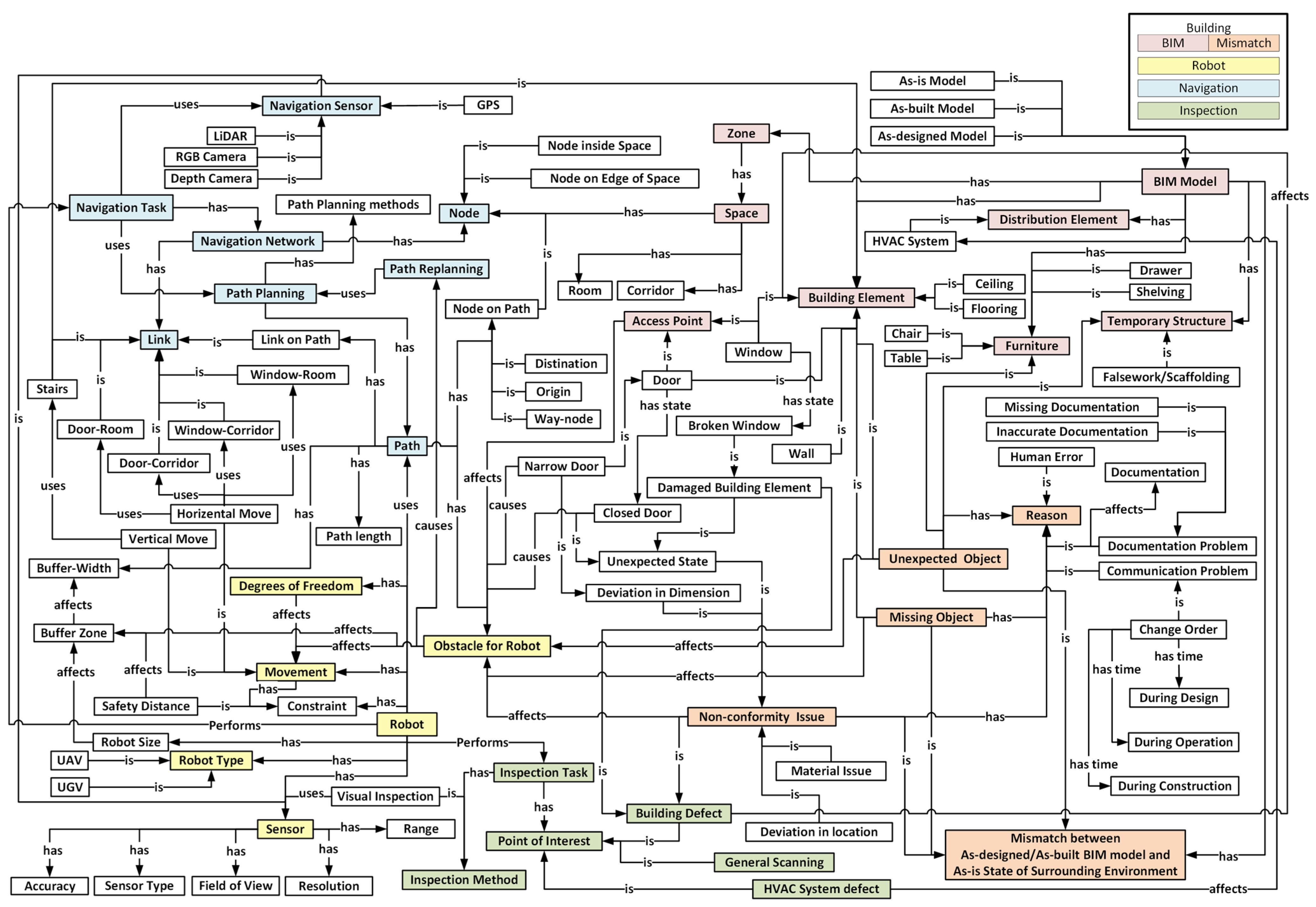
3.2. Components of OBRNIT
3.2.1. Robot Concepts
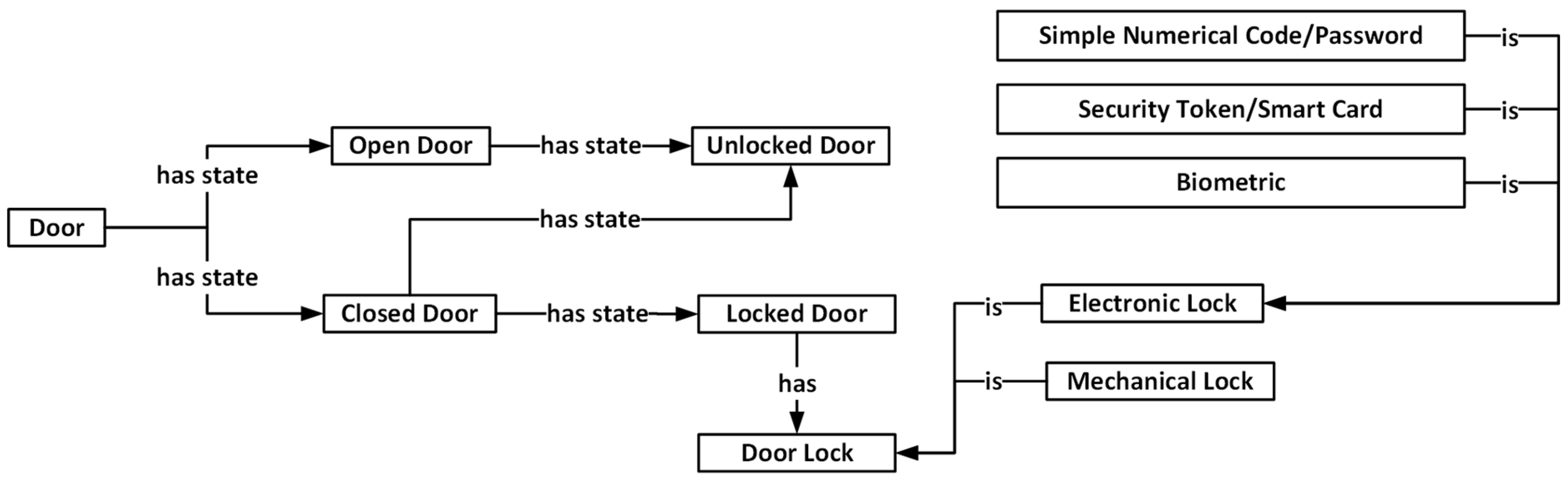
3.2.2. Building Concepts
3.2.3. Navigation Concepts
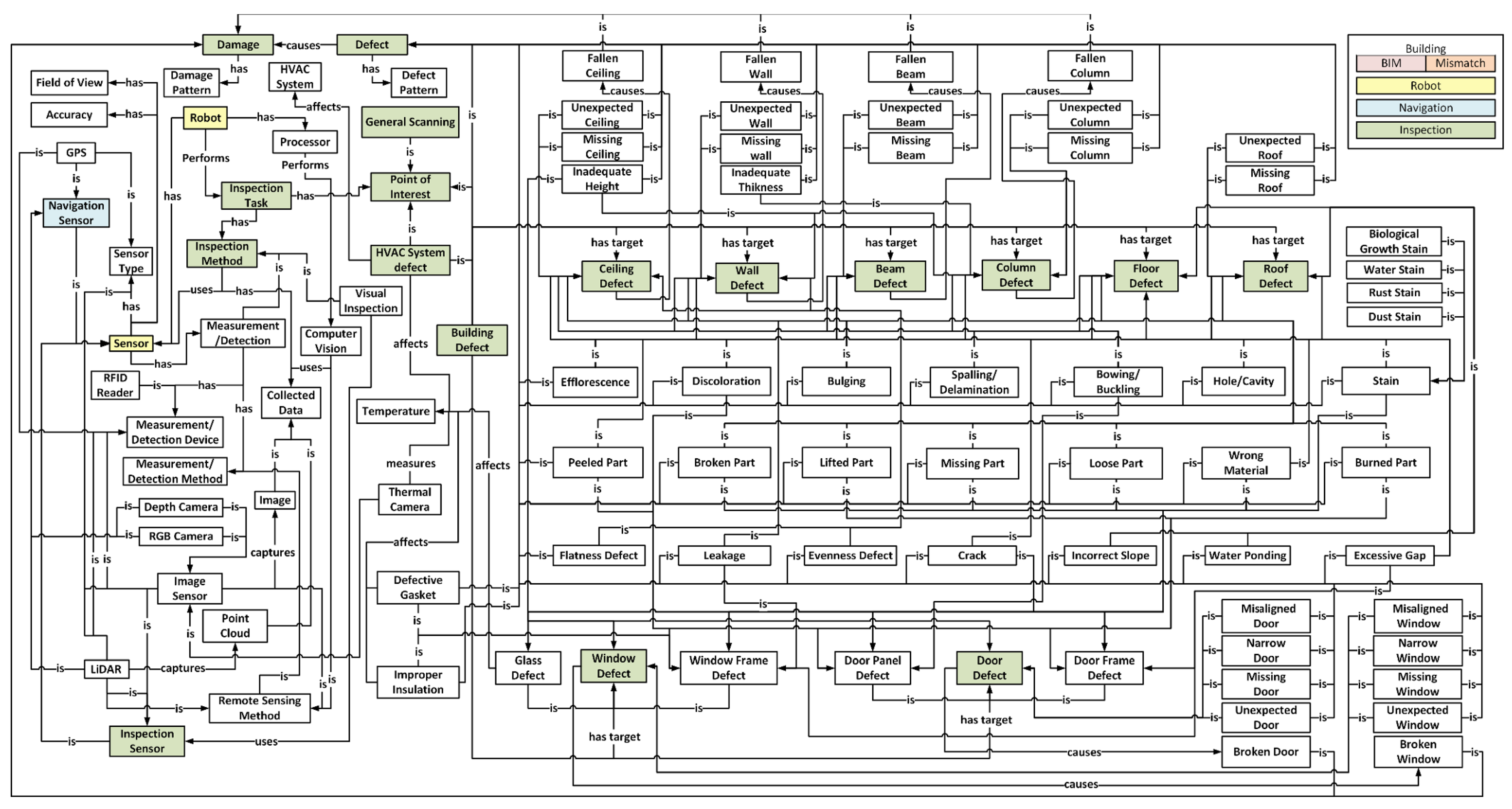
3.2.4. Inspection Concepts
4. Evaluation
4.1. Case Study
4.2. Criteria-Based Evaluation
5. Results and Discussion
6. Contributions, Conclusions, and Future Work
Author Contributions
Funding
Data Availability Statement
Conflicts of Interest
List of Abbreviations
| Abbreviation | Description |
| AEC/FM | Architecture, engineering, construction, and facilities management |
| AUV | Autonomous underwater vehicles |
| BEO | Building Element Ontology |
| BIM | Building information modeling |
| BIMSO | BIM Shared Ontology |
| BMS | Building Management System |
| BOT | Building Topology Ontology |
| CPL | CRAM Plan Language |
| CRAM | Cognitive Robot Abstract Machine |
| DDM | Defect data management |
| DOF | Degrees of freedom |
| DOT | Damage Topology Ontology |
| FOG | Ontology for Geometry Formats |
| GPS | Global Positioning System |
| HVAC | Heating, Ventilation, and Air Conditioning |
| IDEF | Integrated Definition |
| IFC | Industry Foundation Classes |
| LCA | Life Cycle Assessment |
| LiDAR | Light detection and ranging |
| LOAM | Lidar Odometry and Mapping |
| MEP | Mechanical, Electrical, and Plumbing |
| O&M | Operation and maintenance |
| OBRNIT | Ontology for BIM-based robotic navigation and inspection tasks |
| OMG | Ontology for Managing Geometry |
| OPM | Ontology for Property Management |
| OWL | Web ontology language |
| RDF | Resource description framework |
| RFID | Radio Frequency Identification |
| RGB | Red, Green, and Blue |
| ROS | Robot Operating System |
| SLAM | Simultaneous Localization and Mapping |
| UAV | Unmanned aerial vehicle |
| UGV | Unmanned ground vehicle |
| UML | Unified Modeling Language |
| VR | Virtual Reality |
References
- Balaguer, C.; Gimenez, A.; Abderrahim, C.M. ROMA robots for inspection of steel based infrastructures. Ind. Robot. 2002, 29, 246–251. [Google Scholar] [CrossRef]
- Kim, D.; Goyal, A.; Newell, A.; Lee, S.; Deng, J.; Kamat, V.R. Semantic relation detection between construction entities to support safe human-robot collaboration in construction. In Proceedings of the ASCE International Conference on Computing in Civil Engineering: Data, Sensing, and Analytics, Atlanta, GA, USA, 17–19 June 2019; ASCE: Reston, VA, USA, 2019; pp. 265–272. [Google Scholar]
- Open Robotics, ROS. 2020. Available online: https://www.ros.org/ (accessed on 7 July 2020).
- Saigol, Z.; Wang, M.; Ridder, B.; Lane, D.M. The Benefits of Explicit Ontological Knowledge-Bases for Robotic Systems. In Proceedings of the 16th Annual Conference on Towards Autonomous Robotic Systems, Liverpool, UK, 8–10 September 2015; Springer: Liverpool, UK, 2015; pp. 229–235. [Google Scholar]
- Lim, G.H.; Suh, I.H.; Suh, H. Ontology-based unified robot knowledge for service robots in indoor environments. IEEE Trans. Syst. Man Cybern. Part A Syst. Hum. 2010, 41, 492–502. [Google Scholar] [CrossRef]
- BuildingSMART. Industry Foundation Classes Release 4.1. 2018. Available online: https://standards.buildingsmart.org/IFC/RELEASE/IFC4_1/FINAL/HTML/ (accessed on 1 July 2020).
- Zhang, J.; Singh, S. LOAM: Lidar Odometry and Mapping in Real-time. Robot. Sci. Syst. 2014, 2, 401–416. [Google Scholar]
- Akinci, B.; Boukamp, F. Representation and integration of as-built information to IFC based product and process models for automated assessment of as-built conditions. In Proceedings of the 19th ISARC International Symposium on Automation and Robotics in Construction, Washington, DC, USA, 23–25 September 2002; pp. 543–550. [Google Scholar]
- Rasmussen, M.H.; Lefrançois, M.; Schneider, G.F.; Pauwels, P. BOT: The building topology ontology of the W3C linked building data group. Semant. Web 2020, 12, 143–161. [Google Scholar] [CrossRef]
- Hamdan, A.H.; Bonduel, M.; Scherer, R.J. An ontological model for the representation of damage to constructions. In Proceedings of the 7th Linked Data in Architecture and Construction Workshop, London, UK, 19–21 June 2019. [Google Scholar]
- Niknam, M.; Karshenas, S. A shared ontology approach to semantic representation of BIM data. Autom. Constr. 2017, 80, 22–36. [Google Scholar] [CrossRef]
- Tenorth, M.; Beetz, M. KnowRob—Knowledge processing for autonomous personal robots. In Proceedings of the IEEE/RSJ International Conference on Intelligent Robots and Systems, St. Louis, MO, USA, 10–15 October 2009. [Google Scholar]
- Lattanzi, D.; Miller, G. Review of robotic infrastructure inspection systems. J. Infrastruct. Syst. 2017, 23, 04017004. [Google Scholar] [CrossRef]
- Brunner, S.; Kucera, M.; Waas, T. Ontologies used in robotics: A survey with an outlook for automated driving. In Proceedings of the IEEE International Conference on Vehicular Electronics and Safety (ICVES), Vienna, Austria, 27–28 June 2017; pp. 81–84. [Google Scholar]
- Stulp, F.; Beetz, M. Combining declarative, procedural, and predictive knowledge to generate, execute, and optimize robot plans. Robot. Auton. Syst. 2008, 56, 967–979. [Google Scholar] [CrossRef]
- Bahreini, F.; Hammad, A. Towards an ontology for BIM-based robotic navigation and inspection tasks. In Proceedings of the 38th International Symposium on Automation and Robotics in Construction, Dubai, United Arab Emirates, 2–4 November 2021. [Google Scholar]
- Artus, M.; Koch, C. State of the art in damage information modeling for RC bridges–A literature review. Adv. Eng. Inform. 2020, 46, 101171. [Google Scholar] [CrossRef]
- Tayeh, B.A.; Maqsoom, A.; Aisheh, Y.I.A.; Almanassra, M.; Salahuddin, H.; Qureshi, M.I. Factors affecting defects occurrence in the construction stage of residential buildings in Gaza Strip. SN Appl. Sci. 2020, 2, 167. [Google Scholar] [CrossRef]
- Kim, M.K.; Cheng, J.C.; Sohn, H.; Chang, C.C. A framework for dimensional and surface quality assessment of precast concrete elements using BIM and 3D laser scanning. Autom. Constr. 2015, 49, 225–238. [Google Scholar] [CrossRef]
- Park, C.S.; Lee, D.Y.; Kwon, O.S.; Wang, X. A framework for proactive construction defect management using BIM, augmented reality and ontology-based data collection template. Autom. Constr. 2013, 33, 61–71. [Google Scholar] [CrossRef]
- Tekin, H.; Yılmaz, İ.; Koc, K.; Atabay, Ş.; Gürgün, A. Identification of Defective Construction Works during Building Inspections. Proc. Int. Struct. Eng. Constr. 2023, 10, QUA-01-1–QUA-01-5. [Google Scholar] [CrossRef]
- Ding, L.; Li, K.; Zhou, Y.; Love, P.E. An IFC-inspection process model for infrastructure projects: Enabling real-time quality monitoring and control. Autom. Constr. 2017, 84, 96–110. [Google Scholar] [CrossRef]
- Melo, R.R.S.; Costa, D.B.; Alvares, J.S.; Irizarry, J. Applicability of unmanned aerial system (UAS) for safety inspection on construction sites. Saf. Sci. 2017, 98, 174–185. [Google Scholar] [CrossRef]
- Phung, M.D.; Quach, C.H.; Dinh, T.H.; Ha, Q. Enhanced discrete particle swarm optimization path planning for UAV vision-based surface inspection. Autom. Constr. 2017, 81, 25–33. [Google Scholar] [CrossRef]
- Bolourian, N.; Hammad, A. LiDAR-equipped UAV path planning considering potential locations of defects for bridge inspection. Autom. Constr. 2019, 117, 103250. [Google Scholar] [CrossRef]
- Lundeen, K.M.; Kamat, V.R.; Menassa, C.C.; McGee, W. Autonomous motion planning and task execution in geometrically adaptive robotized construction work. Autom. Constr. 2019, 100, 24–45. [Google Scholar] [CrossRef]
- Freimuth, H.; Müller, J.; König, M. Simulating and Executing UAV-Assisted Inspections on Construction Sites. In Proceedings of the 34th ISARC International Symposium on Automation and Robotics in Construction, Taipei, Taiwan, 28 June 2017. [Google Scholar]
- Bahreini, F.; Hammad, A. Dynamic graph CNN based semantic segmentation of concrete defects and as-inspected modeling. Autom. Constr. 2024, 159, 105282. [Google Scholar] [CrossRef]
- Bortolini, R.; Forcada, N. Building inspection system for evaluating the technical performance of existing buildings. J. Perform. Constr. Facil. 2018, 32, 04018073. [Google Scholar] [CrossRef]
- Valença, J.; Morin, K.; Jouen, N.; Olivo, N.; Torres-Gonzalez, M.; Mendes, M.P.; Silva, A. Feeling-BIM: A digital model to support maintenance decisions, based on automatic inspection and dwellers’ feelings. J. Build. Eng. 2024, 87, 108937. [Google Scholar] [CrossRef]
- Metni, N.; Hamel, T. A UAV for bridge inspection: Visual servoing control law with orientation limits. Autom. Constr. 2007, 17, 3–10. [Google Scholar] [CrossRef]
- Chen, W.; Yabuki, N.; Fukuda, T.; Michikawa, T.; Motamedi, A. Development of product model for harbor structures degradation. In Proceedings of the 2nd International Conference on Civil and Building Engineering Informatics (ICCBEI), Tokyo, Japan, 22–24 April 2015. [Google Scholar]
- Motamedi, A.; Yabuki, N.; Fukuda, T. Extending BIM to include defects and degradations of buildings and infrastruc-ture facilities. In Proceedings of the 3rd International Conference on Civil and Building Engineering Informatics, Taipei, Taiwan, 19–21 April 2017. [Google Scholar]
- Hammad, A.; Motamedi, A.; Yabuki, N.; Taher, A.; Bahreini, F. Towards unified ontology for modeling lifecycle inspection and repair information of civil infrastructure systems. In Proceedings of the 17th ICCCBE International Conference on Computing in Civil and Building Engineering, Tampere, Finland, 5–7 June 2018. [Google Scholar]
- Kasireddy, V.; Akinci, B. Towards the integration of inspection data with bridge information models to support visual condition assessment. In Proceedings of the ASCE International Workshop on Computing in Civil Engineering, Austin, TX, USA, 21–23 June 2015. [Google Scholar]
- Ekba, S.; Borovkova, A.; Nikolenko, D.; Koblyuk, D. A systematic approach to technical inspection of construction projects. E3S Web Conf. 2023, 402, 07003. [Google Scholar] [CrossRef]
- Choi, M.; Kim, S.; Kim, S. Semi-automated visualization method for visual inspection of buildings on BIM using 3D point cloud. J. Build. Eng. 2024, 81, 108017. [Google Scholar] [CrossRef]
- Mohamed, M.; Tran, D. Approach for Estimating Inspection Staffing Needs for Highway Construction Projects. Transp. Res. Rec. 2023, 2677, 697–707. [Google Scholar] [CrossRef]
- Furtner, P.; O’Brien, P. Automated Creation of an IFC-4 Compliant Damage Model from a Digital Inspection Supported by AI. ce/papers 2023, 6, 1366–1372. [Google Scholar] [CrossRef]
- Chen, Z.; Chen, L.; Zhou, X.; Huang, L.; Sandanayake, M.; Yap, P.S. Recent technological advancements in BIM and LCA integration for sustainable construction: A review. Sustainability 2024, 16, 1340. [Google Scholar] [CrossRef]
- Tan, Y.; Xu, W.; Chen, P.; Zhang, S. Building defect inspection and data management using computer vision, augmented reality, and BIM technology. Autom. Constr. 2024, 160, 105318. [Google Scholar] [CrossRef]
- Zverovich, V.; Mahdjoubi, L.; Boguslawski, P.; Fadli, F. Analytic prioritization of indoor routes for search and rescue operations in hazardous environments. Comput. Aided Civ. Infrastruct. Eng. 2017, 32, 727–747. [Google Scholar] [CrossRef]
- Shin, H.; Cha, H. Proposing a Quality Inspection Process Model Using Advanced Technologies for the Transition to Smart Building Construction. Sustainability 2023, 15, 815. [Google Scholar] [CrossRef]
- Liang, H.; Lee, S.; Bae, W.; Kim, J.; Seo, S. Towards UAVs in Construction: Advancements, Challenges, and Future Directions for Monitoring and Inspection. Drones 2023, 7, 202. [Google Scholar] [CrossRef]
- Lundeen, K.M.; Kamat, V.R.; Menassa, C.C.; McGee, W. Scene understanding for adaptive manipulation in robotized construction work. Autom. Constr. 2017, 82, 16–30. [Google Scholar] [CrossRef]
- Carra, G.; Argiolas, A.; Bellissima, A.; Niccolini, M.; Ragaglia, M. Robotics in the construction industry: State of the art and future opportunities. In Proceedings of the 35th ISARC on Automation and Robotics in Construction, Berlin, Germany, 20–25 July 2018; pp. 1–8. [Google Scholar]
- Dormehl, L. 98 Percent of Construction Projects Go over Budget. These Robots Could Fix That. 2018. Available online: https://www.digitaltrends.com/cool-tech/doxel-construction-monitoring-robots/ (accessed on 20 January 2020).
- Lin, T.H.; Chiang, P.C.; Putranto, A. Multispecies hybrid bioinspired climbing robot for wall tile inspection. Autom. Constr. 2024, 164, 105446. [Google Scholar] [CrossRef]
- Halder, S.; Afsari, K. Robots in Inspection and Monitoring of Buildings and Infrastructure: A Systematic Review. Appl. Sci. 2023, 13, 2304. [Google Scholar] [CrossRef]
- Patil, S.; Admuthe, V.; Patil, R.; Bhokare, N.; Desai, A.; Chhachwale, S.; Nikam, P.; Desai, D. Construction Site Inspection by Using Drone or UAV. Int. J. Eng. Appl. Sci. Technol. 2023, 7, 101–103. [Google Scholar] [CrossRef]
- Pu, H.; Yang, X.; Li, J.; Guo, R.; Li, H. AutoRepo: A general framework for multi-modal LLM-based automated construction reporting. arXiv 2023, arXiv:2310.07944. [Google Scholar]
- Beetz, M.; Mösenlechner, L.; Tenorth, M. CRAM—A Cognitive Robot Abstract Machine for everyday manipulation in human environments. In Proceedings of the 2010 IEEE/RSJ International Conference on Intelligent Robots and Systems, Taipei, Taiwan, 18–22 October 2010. [Google Scholar]
- Wong, M.O.; Lee, S. A Technical Review on Developing BIM-Oriented Indoor Route Planning. In Proceedings of the International Conference on In Computing in Civil Engineering: Visualization, Information Modeling, and Simulation, Atlanta, GA, USA, 17–19 June 2019; ASCE: Reston, VA, USA, 2019; pp. 336–342. [Google Scholar]
- Belsky, M.; Sacks, R.; Brilakis, I. Semantic enrichment for building information modeling. Comput. Aided Civ. Infrastruct. Eng. 2016, 31, 261–274. [Google Scholar] [CrossRef]
- Lin, Y.H.; Liu, Y.S.; Gao, G.; Han, X.G.; Lai, C.Y.; Gu, M. The IFC-based path planning for 3D indoor spaces. Adv. Eng. Inform. 2013, 27, 189–205. [Google Scholar] [CrossRef]
- Boguslawski, P.; Mahdjoubi, L.; Zverovich, V.; Fadli, F. Automated construction of variable density navigable networks in a 3D indoor environment for emergency response. Autom. Constr. 2016, 72, 115–128. [Google Scholar] [CrossRef]
- Hou, Y.; Ju, Y. A Method for Robot Indoor Path Planning Using BIM Based on A* Algorithm. In Proceedings of the International Conference on Electronic Technology, Communication, and Information (ICETCI), Changchun, China, 26–28 May 2023. [Google Scholar]
- Liu, J.; Chen, X.; Xiao, J.; Lin, S.; Zheng, Z.; Lu, H. Hybrid Map-Based Path Planning for Robot Navigation in Unstructured Environments. In Proceedings of the International Conference on Intelligent Robots and Systems (IROS), Detroit, MI, USA, 1–5 October 2023; pp. 2216–2223. [Google Scholar]
- Zhai, R.; Zou, J.; Gan, V.J.; Han, X.; Wang, Y.; Zhao, Y. Semantic enrichment of BIM with IndoorGML for quadruped robot navigation and automated 3D scanning. Autom. Constr. 2024, 166, 105605. [Google Scholar] [CrossRef]
- Gruber, T.R. Toward principles for the design of ontologies used for knowledge sharing. Int. J. Hum. Comput. Stud. 1995, 43, 907–928. [Google Scholar] [CrossRef]
- Gaševic, D.; Djuric, D.; Devedžic, V. Model Driven Engineering and Ontology Development; Springer Science and Business Media: Berlin/Heidelberg, Germany, 2009. [Google Scholar]
- Stanford University, Stanford Center for Biomedical Informatics Research. 2019. Available online: https://protege.stanford.edu/about.php (accessed on 2 January 2019).
- Staab, S.; Maedche, A. Ontology engineering beyond the modeling of concepts and relations. In Proceedings of the ECAI Workshop on Ontologies and Problem-Solving Methods, Berlin, Germany, 21–22 August 2000. [Google Scholar]
- McGuinness, D.L.; Harmelen, F. OWL Web Ontology Language Overview. 2004. Available online: https://www.researchgate.net/publication/200034408_OWL_Web_Ontology_Language---Overview (accessed on 10 June 2022).
- BuildingSMART. ifcOWL. 2019. Available online: https://technical.buildingsmart.org/standards/ifc/ifc-formats/ifcowl/ (accessed on 22 July 2020).
- Cacciotti, R.; Blaško, M.; Valach, J. A diagnostic ontological model for damages to historical constructions. J. Cult. Herit. 2015, 16, 40–48. [Google Scholar] [CrossRef]
- Pauwels, P. Building Element Ontology. 2018. Available online: https://pi.pauwel.be/voc/buildingelement/index-en.html (accessed on 26 February 2021).
- Pauwels, P. Distribution Element Ontology. 2019. Available online: https://pi.pauwel.be/voc/distributionelement/index-en.html (accessed on 27 February 2021).
- Rasmussen, M.; Lefrançois, M.; Bonduel, M.; Hviid, C.; Karlshøj, J. OPM: An ontology for describing properties that evolve over time. In Proceedings of the 6th Linked Data in Architecture and Construction Workshop, London, UK, 19–21 June 2018. [Google Scholar]
- Wagner, A.; Bonduel, M.; Pauwels, P.; Uwe, R. Relating geometry descriptions to its derivatives on the web. In Proceedings of the European Conference on Computing in Construction, Crete, Greece, 10–12 July 2019. [Google Scholar]
- Bonduel, M.; Wagner, A.; Pauwels, P.; Vergauwen, M.; Klein, R. Including widespread geometry formats in semantic graphs using RDF literals. In Proceedings of the European Conference on Computing in Construction, Crete, Greece, 10–12 July 2019. [Google Scholar]
- Kokar, M.M.; Matheus, C.J.; Baclawski, K. Ontology-based situation awareness. Inf. Fusion 2009, 10, 83–98. [Google Scholar] [CrossRef]
- Haidegger, T.; Barreto, M.; Gonçalves, P.; Habib, M.K.; Ragavan, S.K.V.; Li, H.; Vaccarella, A.; Perrone, R.; Prestes, E. Applied ontologies and standards for service robots. Robot. Auton. Syst. 2013, 61, 1215–1223. [Google Scholar] [CrossRef]
- Barbera, T.; Albus, J.; Messina, E.; Schlenoff, C.; Horst, J. How task analysis can be used to derive and organize the knowledge for the control of autonomous vehicles. Robot. Auton. Syst. 2004, 49, 67–78. [Google Scholar] [CrossRef]
- Kostavelis, I.; Gasteratos, A. Semantic mapping for mobile robotics tasks: A survey. Robot. Auton. Syst. 2015, 66, 86–103. [Google Scholar] [CrossRef]
- Bourreau, P.; Charbel, N.; Werbrouck, J.; Senthilvel, M.; Pauwels, P.; Beetz, J. Multiple inheritance for a modular BIM. In Le BIM et L’évolution des Pratiques: Ingénierie et Architecture, Enseignement et Recherche; Eyrolles: Paris, France, 2020. [Google Scholar]
- Hamledari, H.; Rezazadeh Azar, E.; McCabe, B. IFC-based development of as-built and as-is BIMs using construction and facility inspection data: Site-to-BIM data transfer automation. J. Comput. Civ. Eng. 2018, 32, 04017075. [Google Scholar] [CrossRef]
- Wang, Q.; Kim, M.K.; Cheng, J.C.; Sohn, H. Automated quality assessment of precast concrete elements with geometry irregularities using terrestrial laser scanning. Autom. Constr. 2016, 68, 170–182. [Google Scholar] [CrossRef]
- Adan, A.; Prieto, S.A.; Quintana, B.; Prado, T.; Garcia, J. An autonomous thermal scanning system with which to obtain 3D thermal models of buildings. In Proceedings of the 35th CIB W78 Conference on IT in Design, Construction, and Management, Chicago, IL, USA, 9 October 2018; Springer: Chicago, IL, USA, 2019; pp. 489–496. [Google Scholar]
- Freimuth, H.; König, M. A framework for automated acquisition and processing of As-built data with autonomous unmanned aerial vehicles. Sensors 2019, 19, 4513. [Google Scholar] [CrossRef]
- La, H.M.; Dinh, T.H.; Pham, N.H.; Ha, Q.P.; Pham, A.Q. Automated robotic monitoring and inspection of steel structures and bridges. Robotica 2019, 37, 947–967. [Google Scholar] [CrossRef]
- Wang, J.; Luo, C. Automatic Wall Defect Detection Using an Autonomous Robot: A Focus on Data Collection. In Proceedings of the ASCE International Conference on Computing in Civil Engineering: Data, Sensing, and Analytics, Atlanta, GA, USA, 17–19 June 2019; American Society of Civil Engineers: Reston, VA, USA, 2019; pp. 312–319. [Google Scholar]
- Wang, C.; Chi, W.; Sun, Y.; Meng, M.Q.H. Autonomous robotic exploration by incremental road map construction. IEEE Trans. Autom. Sci. Eng. 2019, 16, 1720–1731. [Google Scholar] [CrossRef]
- Freimuth, H.; König, M. Planning and executing construction inspections with unmanned aerial vehicles. Autom. Constr. 2018, 96, 540–553. [Google Scholar] [CrossRef]
- Menendez, E.; Victores, J.G.; Montero, R.; Martínez, S.; Balaguer, C. Tunnel structural inspection and assessment using an autonomous robotic system. Autom. Constr. 2018, 87, 117–126. [Google Scholar] [CrossRef]
- Rea, P.; Ottaviano, E. Design and development of an Inspection Robotic System for indoor applications. Robot. Comput. Integr. Manuf. 2018, 49, 143–151. [Google Scholar] [CrossRef]
- Sutter, B.; Lelevé, A.; Pham, M.T.; Gouin, O.; Jupille, N.; Kuhn, M.; Lulé, P.; Michaud, P.; Rémy, P. A semi-autonomous mobile robot for bridge inspection. Autom. Constr. 2018, 91, 111–119. [Google Scholar] [CrossRef]
- Krawczyk, J.M.; Mazur, A.M.; Sasin, T.; Stokłosa, A.W. Infrared building inspection with unmanned aerial vehicles. Pr. Inst. Lotnictwa 2015, 3, 32–48. [Google Scholar] [CrossRef]
- Saigol, Z.; Ridder, B.; Wang, M.; Dearden, R.; Fox, M.; Hawes, N.; Lane, D.M.; Long, D. Efficient search for known objects in unknown environments using autonomous indoor robots. In Proceedings of the IROS Workshop on Task Planning for Intelligent Robots in Service and Manufacturing, Hamburg, Germany, 2 October 2015. [Google Scholar]
- Lim, R.S.; La, H.M.; Sheng, W. A robotic crack inspection and mapping system for bridge deck maintenance. IEEE Trans. Autom. Sci. Eng. 2014, 11, 367–378. [Google Scholar] [CrossRef]
- Roca, D.; Laguela, S.; Diaz-Vilarino, L.; Armesto, J.; Arias, P. Low-cost aerial unit for outdoor inspection of building facades. Autom. Constr. 2013, 36, 128–135. [Google Scholar] [CrossRef]
- Yu, S.N.; Jang, J.H.; Han, C.S. Auto inspection system using a mobile robot for detecting concrete cracks in a tunnel. Autom. Constr. 2007, 16, 255–261. [Google Scholar] [CrossRef]
- Prestes, E.; Carbonera, J.L.; Fiorini, S.R.; Jorge, V.A.; Abel, M.; Madhavan, R.; Locoro, A.; Goncalves, P.; Barreto, M.E.; Habib, M.; et al. Towards a core ontology for robotics and automation. Robot. Auton. Syst. 2013, 61, 1193–1204. [Google Scholar] [CrossRef]
- Noy, N.F.; Griffith, N.; Musen, M.A. Collecting community-based mappings in an ontology repository. In Proceedings of the 7th ISWC International Conference on Semantic Web, Karlsruhe, Germany, 16–30 October 2008. [Google Scholar]
- Brank, J.; Grobelnik, M.; Mladenic, D. A survey of ontology evaluation techniques. In Proceedings of the Conference on Data Mining and Data Warehouses, Copenhagen, Denmark, 22–26 August 2005; Citeseer: Ljubljana, Slovenia, 2005; pp. 166–170. [Google Scholar]
- KBSI. IDEF–Integrated DEFinition Methods (IDEF). 2020. Available online: https://www.idef.com/ (accessed on 18 July 2020).
- Taher, A.; Vahdatikhaki, F.; Hammad, A. Towards Developing an Ontology for Earthwork Operation. In Proceedings of the ASCE International Workshop on Computing in Civil Engineering, Washington, DC, USA, 25–27 June 2017. [Google Scholar]
- Klingbeil, E.; Saxena, A.; Ng, A.Y. Learning to open new doors. In Proceedings of the 2010 IEEE/RSJ International Conference on Intelligent Robots and Systems, Taipei, Taiwan, 18–22 October 2010; IEEE: Taipei, Taiwan, 2010; pp. 2751–2757. [Google Scholar]
- Cobalt Robotics. The First Security Industry Solution to Allow Robots to Open Doors. 2019. Available online: https://www.cobaltai.com/cobalt-robotics-announces-door-integration-solution/ (accessed on 30 January 2020).
- Richardson, B. Defects and Deterioration in Buildings: A Practical Guide to the Science and Technology of Material Failure, 2nd ed.; Routledge: London, UK, 2002. [Google Scholar]
- Lohani, B.; Singh, R. Effect of data density, scan angle, and flying height on the accuracy of building extraction using LiDAR data. Geocarto Int. 2008, 32, 81–94. [Google Scholar] [CrossRef]
- Haghighi, P.D.; Burstein, F.; Zaslavsky, A.; Arbon, P. Development and evaluation of ontology for intelligent decision support in medical emergency management for mass gatherings. Decis. Support Syst. 2013, 54, 1192–1204. [Google Scholar] [CrossRef]
- Yu, J.; Thom, J.A.; Tam, A. Requirements-oriented methodology for evaluating ontologies. Inf. Syst. 2009, 34, 766–791. [Google Scholar] [CrossRef]
- Oxford University, The Knowledge Representation and Reasoning Group, HermiT OWL Reason. 2019. Available online: http://www.hermit-reasoner.com/ (accessed on 10 June 2020).
- Hercz, T.; Liu, W. Mecabot User Manual. 2023. Available online: https://cdn.robotshop.com/rbm/815d1a40-62cd-43a6-8dad-e05323e8953a/e/e350701f-db45-4050-bb03-255ea0a04018/c71e4dfe_mecabot-user-manual-v.20230330.pdf (accessed on 1 March 2023).
- Compton, M.; Barnaghi, P.; Bermudez, L.; Garcia-Castro, R.; Corcho, O.; Cox, S.; Graybeal, J.; Hauswirth, M.; Henson, C.; Herzog, A.; et al. The SSN ontology of the W3C semantic sensor network incubator group. J. Web Semant. 2012, 17, 25–32. [Google Scholar] [CrossRef]


| Q1 | How to locate the defect in the BIM model? |
| Q2 | How to relate the mobility characteristics of the robot with the conditions of the building based on the BIM model? |
| Q3 | How to benefit from the BIM model in defining the path of the robot? |
| Q4 | How to use the sensors of the robot to find the mismatches with the BIM model for replanning the path of the robot? |
| Q5 | How to select the suitable sensors for the robot for the specific inspection task? |
| Concept’s Source | Example Concepts |
|---|---|
| Concepts reused from BEO | Beam, column, covering (ceiling and flooring), door, stair, wall, and window |
| Concepts reused from BOT | Space and zone |
| Concepts reused from ifcOWL | HVAC system |
| Room and corridor | |
| Furniture (e.g., table and shelving) | |
| Concepts adopted from BMS | Open door, closed door, locked door and unlocked door |
| New building concepts | Access point |
| Temporary structure (e.g., falsework/scaffolding) | |
| BIM model (as-designed, as-built, and as-is) | |
| A mismatch between as-designed/as-built BIM and as-is state of the surrounding environment (missing objects, unexpected objects, and non-conformity issues), deviation in dimension, deviation in location, material issue, unexpected state, and damaged building element | |
| Mismatch reason (communication problem, documentation problem, or human error), change order, inaccurate documentation, and missing documentation |
| Concept in OBRNIT | |
|---|---|
| Point of interest | Ceiling defect |
| Type of defect | Leakage |
| Inspection method | Measurement/detection |
| Measurement/detection device | RGB camera |
| Concept in OBRNIT | Specifications | |
|---|---|---|
| Robot type (UGV) | Mecabot Pro | |
| Movement | Horizontal movement | |
| Sensor type | LS LiDAR (Leishen C16 3D) | 360-degree scanning range and surroundings perception |
| Depth camera (Orbbec Astra) | RGBD image capturing for a range of uses including gesture control, skeleton tracking, 3D scanning, and point cloud development | |
| VR camera (Insta360 ONE RS) | 360-degree view for photos and video capturing | |
| Degrees of freedom | 3 degrees of freedom | |
| Size | Length | 58.1 cm |
| Width | 54.1 cm | |
| Height | 22.5 cm | |
| IfcEntity | Name | Tag | Concept in OBRNIT | |
|---|---|---|---|---|
| Room 9-215 | IfcColumn | M_Round Column: 610 mm Diameter | 364991 | Column |
| IfcCovering | Compound Ceiling: 600 × 600 mm grid 2, white | 378778 | Ceiling (point of interest for leakage inspection) | |
| IfcCurtainWall | Curtain Wall: Storefront | 363008 | Curtain wall | |
| IfcDoor | M_Single-Flush: 0915 × 2134 mm: 379291 | 379291 | Door | |
| IfcFurniture | M_Furniture_System-Standing_Desk-Rectangular: 1500 × 750 mm | 372571 | Table | |
| IfcFurniture | 373006 | |||
| IfcFurniture | 373129 | |||
| IfcFurniture | 373192 | |||
| IfcFurniture | 373239 | |||
| IfcFurniture | 373486 | |||
| IfcFurniture | 373630 | |||
| IfcFurniture | 374087 | |||
| IfcFurniture | 374640 | |||
| IfcFurniture | 374723 | |||
| IfcFurniture | M_Chair—Executive | 376992 | Chair | |
| IfcFurniture | 377394 | |||
| IfcFurniture | 377583 | |||
| IfcFurniture | 377646 | |||
| IfcFurniture | 377711 | |||
| IfcFurniture | 377776 | |||
| IfcFurniture | 377859 | |||
| IfcFurniture | 377916 | |||
| IfcFurniture | 377983 | |||
| IfcFurniture | 378050 | |||
| IfcFurniture | M_Shelving: 1240 × 0305 × 1500 mm | 368134 | Shelving | |
| IfcFurniture | 370460 | |||
| IfcFurniture | M_Cabinet-File 4 Drawer: 1000 × 0457 mm | 367042 | Drawer | |
| IfcFurniture | 367118 | |||
| IfcFurniture | 368542 | |||
| IfcSlab | Floor: Generic Floor—400 mm | 359802 | Flooring | |
| IfcSpace | Room—9-215 | Room | ||
| IfcWallStandardCase | Basic Wall: Interior—138 mm Partition | 360817 | Wall | |
| IfcWallStandardCase | 360875 | |||
| IfcWallStandardCase | 360745 | |||
| IfcWallStandardCase | 361005 | |||
| IfcWallStandardCase | 361035 | |||
| IfcWallStandardCase | Basic Wall: steel—200 mm concrete masonry unit (CMU) | 361214 | ||
| IfcBuildingElementProxy | Elevator: 1300 × 950 mm | 263782 | Transport element -elevator | |
| IfcBuildingElementProxy | 263642 | |||
| IfcBuildingElementProxy | 263853 | |||
| IfcBuildingElementProxy | Site_Scaffolding | 321511 | Falsework/scaffolding | |
| IfcSpace | Corridor—9-A1 | - | Corridor | |
| IfcSpace | Corridor—9-A2 | - | ||
| IfcSpace | Corridor—9-A3 | - | ||
| IfcSpace | Corridor—9-A4 | - | ||
| IfcStair | Assembled Stair: 7” max riser 11” tread | 258349 | Stair | |
| Concept in OBRNIT | |||
|---|---|---|---|
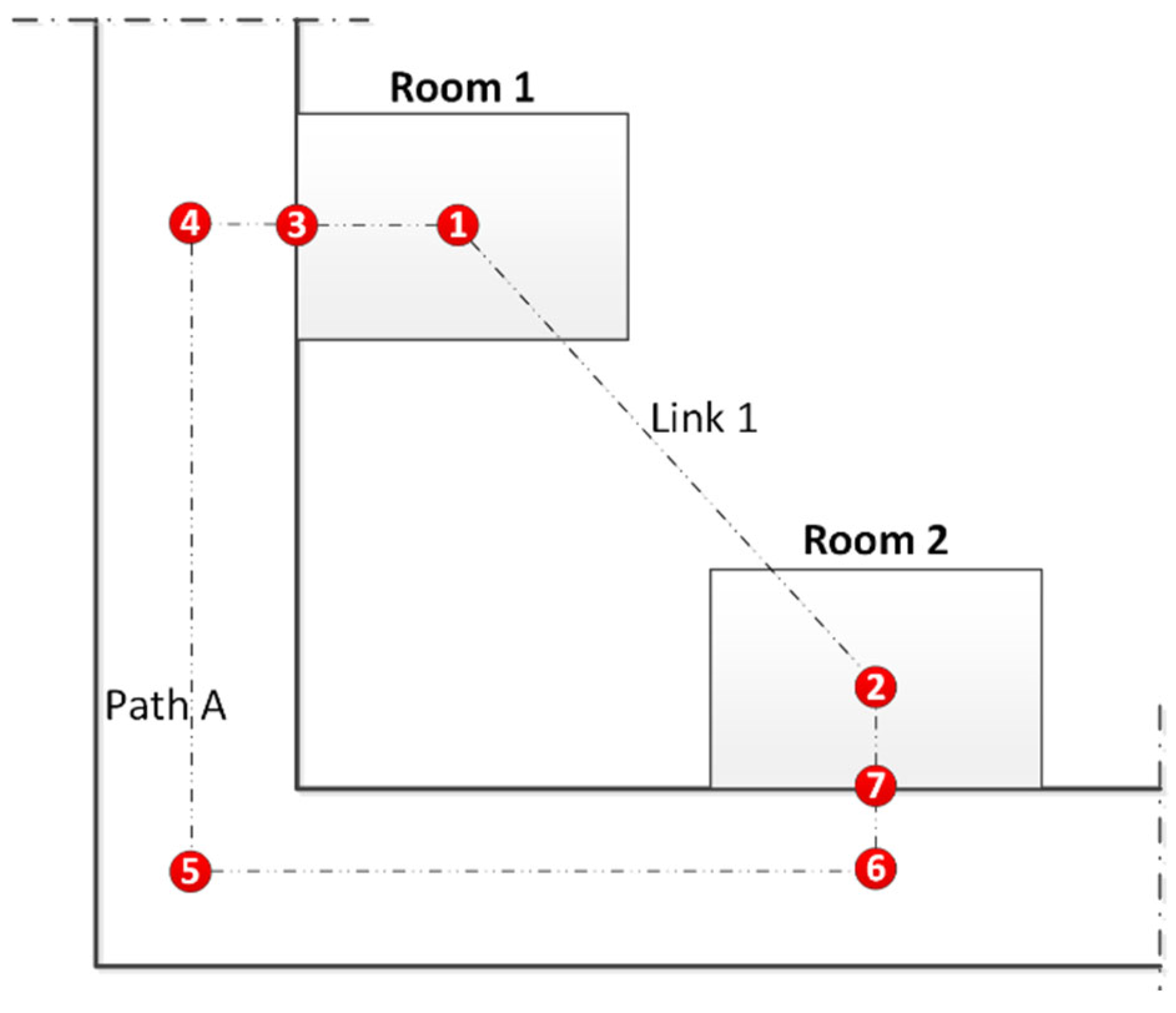
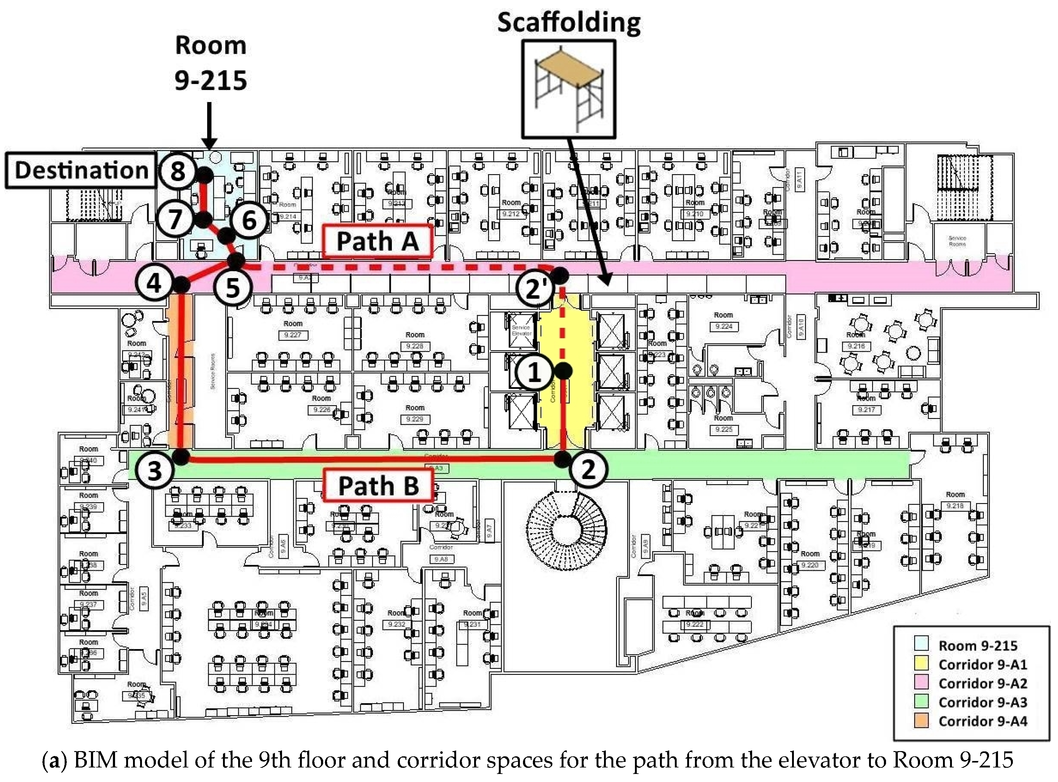
| Parts of the Path to Reach Inspection Point of Interest | Links Connecting Nodes | Obstacles for Robot | |
| Horizontal path in corridors on the 9th floor | Path A | 1-2‘-5 | Scaffoldings, walls, and door |
| Path B | 1-2-3-4-5 | Walls and door | |
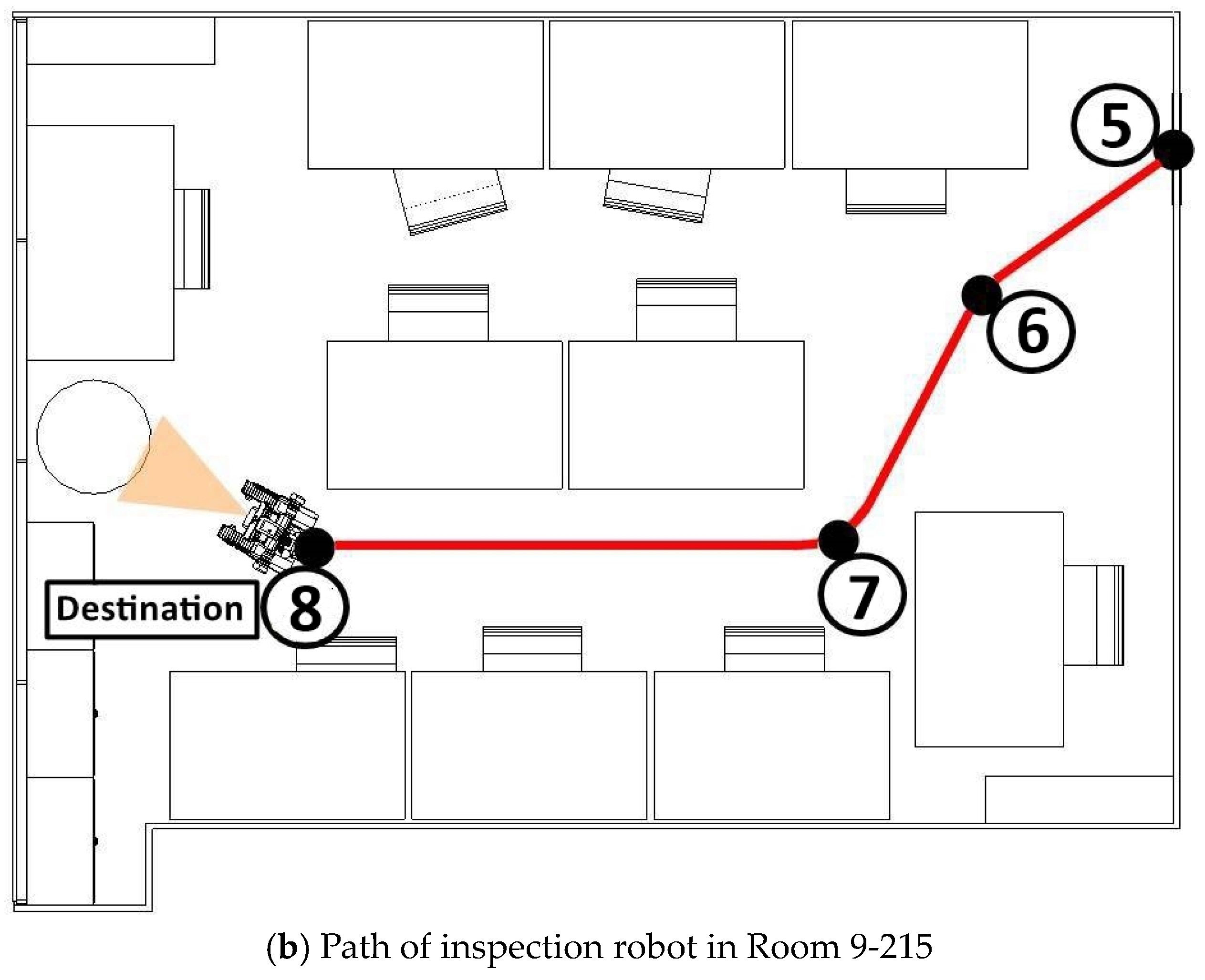
| Horizontal path inside Room 9-215 | 5-6-7-8 | Chairs and tables | |
| Q No | Ave. | SD | Results | |||||
|---|---|---|---|---|---|---|---|---|
| Q2 | 1.75 | 0.65 | Strongly agree | Agree | Neither agree nor disagree | Disagree | Strongly disagree | No answer |
| 36.36% | 51.52% | 12.12% | 0% | 0% | 0% | |||
| Q3 | 2.29 | 0.72 | Very clear | Clear | Somewhat clear | Not so clear | Not clear at all | No answer |
| 9.38% | 56.25% | 25% | 6.25% | 0% | 3.13% | |||
| Q4 | 2.06 | 0.61 | Very comprehensive | Comprehensive | Somewhat comprehensive | Not comprehensive | Missing lots of concepts | No answer |
| 15.63% | 59.38% | 21.88% | 0% | 0% | 3.13% | |||
| Q5 | 2 | 0.58 | Very clear | Clear | Somewhat clear | Not so clear | Not clear at all | No answer |
| 15.63% | 59.38% | 15.63% | 0% | 0% | 9.38% | |||
| Q6 | 2.09 | 0.73 | Very comprehensive | Comprehensive | Somewhat comprehensive | Not comprehensive | Missing lots of concepts | No answer |
| 18.75% | 53.13% | 21.88% | 3.13% | 0% | 3.13% | |||
| Q7 | 1.87 | 0.54 | Strongly agree | Agree | Neither agree nor disagree | Disagree | Strongly disagree | No answer |
| 21.88% | 68.75% | 9.38% | 0% | 0% | 0% | |||
| Q8 | 1.78 | 0.54 | Strongly agree | Agree | Neither agree nor disagree | Disagree | Strongly disagree | No answer |
| 28.13% | 65.63% | 6.25% | 0% | 0% | 0% | |||
Disclaimer/Publisher’s Note: The statements, opinions and data contained in all publications are solely those of the individual author(s) and contributor(s) and not of MDPI and/or the editor(s). MDPI and/or the editor(s) disclaim responsibility for any injury to people or property resulting from any ideas, methods, instructions or products referred to in the content. |
© 2024 by the authors. Licensee MDPI, Basel, Switzerland. This article is an open access article distributed under the terms and conditions of the Creative Commons Attribution (CC BY) license (https://creativecommons.org/licenses/by/4.0/).
Share and Cite
Bahreini, F.; Nasrollahi, M.; Taher, A.; Hammad, A. Ontology for BIM-Based Robotic Navigation and Inspection Tasks. Buildings 2024, 14, 2274. https://doi.org/10.3390/buildings14082274
Bahreini F, Nasrollahi M, Taher A, Hammad A. Ontology for BIM-Based Robotic Navigation and Inspection Tasks. Buildings. 2024; 14(8):2274. https://doi.org/10.3390/buildings14082274
Chicago/Turabian StyleBahreini, Fardin, Majid Nasrollahi, Alhusain Taher, and Amin Hammad. 2024. "Ontology for BIM-Based Robotic Navigation and Inspection Tasks" Buildings 14, no. 8: 2274. https://doi.org/10.3390/buildings14082274