Abstract
Collision accidents involving construction vehicles and workers frequently occur at construction sites. Computer vision (CV) technology presents an efficient solution for collision-risk pre-warning. However, CV-based methods are still relatively rare and need an enhancement of their performance. Therefore, a novel three-stage collision-risk pre-warning model for construction vehicles and workers is proposed in this paper. This model consists of an object-sensing module (OSM), a trajectory prediction module (TPM), and a collision-risk assessment module (CRAM). In the OSM, the YOLOv5 algorithm is applied to identify and locate construction vehicles and workers; meanwhile, the DeepSORT algorithm is applied to the real-time tracking of the construction vehicles and workers. As a result, the historical trajectories of vehicles and workers are sensed. The original coordinates of the data are transformed to common real-world coordinate systems for convenient subsequent data acquisition, comparison, and analysis. Subsequently, the data are provided to a second stage (TPM). In the TPM, the optimized transformer algorithm is used for a real-time trajectory prediction of the construction vehicles and workers. In this paper, we enhance the reliability of the general object detection and trajectory prediction methods in the construction environments. With the assistance afforded by the optimization of the model’s hyperparameters, the prediction horizon is extended, and this gives the workers more time to take preventive measures. Finally, the prediction module indicates the possible trajectories of the vehicles and workers in the future and provides these trajectories to the CRAM. In the CRAM, the worker’s collision-risk level is assessed by a multi-factor-based collision-risk assessment rule, which is innovatively proposed in the present work. The multi-factor-based assessment rule is quantitatively involved in three critical risk factors, i.e., velocity, hazardous zones, and proximity. Experiments are performed within two different construction site scenarios to evaluate the effectiveness of the collision-risk pre-warning model. The research results show that the proposed collision pre-warning model can accurately predict the collision-risk level of workers at construction sites, with good tracking and predicting effect and an efficient collision-risk pre-warning strategy. Compared to the classical models, such as social-GAN and social-LSTM, the transformer-based trajectory prediction model demonstrates a superior accuracy, with an average displacement error of 0.53 m on the construction sites. Additionally, the optimized transformer model is capable of predicting six additional time steps, which equates to approximately 1.8 s. The collision pre-warning model proposed in this paper can help improve the safety of construction vehicles and workers.
1. Introduction
The construction industry is widely recognized as one of the most hazardous sectors worldwide [1,2]. According to the Bureau of Labor Statistics (BLS), there were 5190 fatal workplace injuries recorded in the U.S. in 2021, marking an alarming increase of 8.9% compared to the previous year [3]. Similarly, from 2016 to 2021, more than 3000 workers in the construction industry lost their lives annually in China [4]. Collisions between workers and construction vehicles (e.g., dump trucks and cranes) stand out as a prominent cause of worker casualties [5,6].
Common management methods of construction safety, which rely on the manual monitoring of safety management, have high labor intensity and personnel costs. These methods are difficult to monitor continuously and are easily affected by subjectivity and human error, i.e., misjudgments or overlooked factors [7]. The application of wearable IoT sensors and wireless communication technologies could monitor the environments of construction sites in real time (including radio frequency identification (RFID) [8], global positioning system (GPS) [9], and Bluetooth [10]), which could provide continuous surveillance and immediate alerts [11]. However, the above methods have limited data dimensions and cannot comprehensively capture and analyze the complex information of the surrounding environment. In recent years, computer vision (CV) technology has developed rapidly. CV-based safety risk monitoring, characterized by rich data and the comprehensive monitoring of objects, has been widely applied due to its advantages of non-contact application, continuous operation, and strong scalability and flexibility [12]. It has been utilized in the collision-safety monitoring of construction vehicles and workers [13].
Research efforts based on CV technology primarily focus on identifying the current safety status of workers through statistics [14]. The tracking and prediction of object trajectories to pre-emptively assess risks have been proposed as a promising solution. Studies have shown that the prediction of future accidents is a more important consideration [15]. However, the complexity and diversity of objects and environmental factors in construction sites limit the effectiveness of general CV-based methods for collision warnings addressing possible contact between workers and vehicles. As a result, the accuracy and efficiency of these CV methods need further improvement. Additionally, construction sites are labor-intensive, and collisions are often caused by multiple risk factors [16]. Thus, it is crucial for risk warning technology development to adequately consider the multiple factors and conduct scientific assessments of the collision risks.
To address these limitations and improve the accuracy and scientific basis of the collision-risk warning system, this paper initially proposes a three-stage combined collision pre-warning (3S-CCW) method for construction vehicles and workers. By employing trajectory tracking and prediction techniques for the collision subjects, this method achieves an adequate risk pre-warning. The 3S-CCW method consists of three interconnected modules: target perception, trajectory prediction, and risk assessment. In the target perception (TP) module, a YOLOv5-DeepSORT model [17] is used for object recognition and tracking, enabling us to obtain the real-time locations and the historical trajectory data of the construction vehicles and workers. Based on these fundamental data, we utilize a transformer-based trajectory prediction model [18] to forecast the trajectories of these objects. By using a custom dataset, the reliability levels of the general object detection and trajectory prediction methods in the construction site environment are enhanced, and by optimizing the model’s hyperparameters, the prediction duration is extended to give the workers additional time to respond and prevent accidents. Finally, in the risk assessment (RS) module, a set of innovative collision-risk rules is designed to integrate three key risk factors, i.e., speed, hazardous zones, and proximity, into the risk assessment rules after quantification. The performance of this method is validated through two field experiments, demonstrating its practicality and effectiveness. The results show that the 3S-CCW model accurately and swiftly tracks the workers and construction vehicles, predicts their trajectories, and assesses the safety levels of workers, which could provide a new approach to preventing the collisions on the construction sites.
The remainder of this paper is outlined as follows: Section 2 describes the related studies and limitations. Section 3 introduces the three modules of the proposed collision pre-warning model, i.e., object-sensing module (OSM), a trajectory prediction module (TPM), and a collision-risk assessment module (CRAM). Section 4 describes the experiments used to evaluate the technical approaches and verify the effectiveness of the proposed method using a construction case. Section 5 summarizes the study, presenting the limitations and avenues for future research.
2. Review of Related Studies
2.1. Related Studies on Object Tracking at Construction Sites
Object tracking aims to generate the trajectories of objects over time using algorithms, after determining the targets’ locations (e.g., workers and vehicles) in each frame of video data. In the construction management, current research mainly applies the established visual tracking techniques to the field of computer vision. The point and kernel tracking [19] methods are the most common object-tracking methods. Point tracking is a feature-based method that tracks targets by identifying and matching feature points across the consecutive frames. For instance, Park et al. [20] used point tracking to monitor the workers and materials at construction sites. The advantages of this method are its ability to handle scenarios with partial occlusion and complex backgrounds. However, it heavily relies on the feature point selection and is sensitive to the illumination variation and signal noises. In contrast, kernel tracking is a region-based method that tracks targets by locating their region in the consecutive frames [21]. This approach has the advantages of handling changes in the shapes and sizes of targets. It could be applied to the tracking of multiple workers or vehicles at a construction site [22]. The disadvantages, however, include a high computational complexity and poor real-time performance. Considering the complexity of the construction site environment and the rapid occurrence of accidents, object-tracking algorithms must achieve a high level of real-time performance and accuracy.
Point and kernel tracking methods often fail to meet the above demands. Studies showed that the deep learning-based object-tracking methods could achieve a higher tracking accuracy [23,24,25,26]. Multi-object-tracking algorithms based on deep learning could be divided into the Detection Free Tracking (DFT) method and the Tracking by Detection (TBD) method. The DFT method performs an object detection and tracking simultaneously, resulting in a higher tracking speed. For example, Zhang et al. [27] proposed a Fair MOT multi-object-tracking algorithm, which combines detection with the re-ID feature extraction network and tests its performance on public datasets. Examples of such algorithms include CenterTrack [28] and Tracktor [29]. In the environment of complex constructions, however, tracking accuracy may be lower due to the occlusions and frequent changes. TBD method performs an object detection and tracking independently. For example, Wu et al. [30] used YOLOv4-DeepSORT multi-target tracking algorithm to track workers and trucks on a construction site. Although TBD is not as fast as DFT in terms of tracking speed, it relies on a structure, separating the detection and tracking, which results in a higher accuracy. YOLOv5-DeepSORT is a real-time object-tracking algorithm, using YOLOv5 for object detection and DeepSORT for object tracking. It demonstrates a powerful performance on the publicly available MOT17 dataset [31], a public object-tracking dataset. It accurately tracks objects in a complex construction environment.
2.2. Related Studies on Deep Learning-Based Trajectory Prediction
Trajectory prediction has been extensively studied in related fields, such as those of autonomous driving and robotics [32,33]. Most of the previous methods of trajectory prediction included dynamic models. They used linear dynamic models to recursively estimate the future locations and velocities of the targets, including Markov processes, Bayesian models, and Gaussian regression models [34,35,36]. However, these methods only considered the objects themselves, and rarely evaluated the influence on other objects’ trajectories. Therefore, they are applicable to the specific scenarios with simple motion patterns but they lack generalizability in different scenarios. Data-driven deep learning methods have recently gained popularity by simplifying the modeling of complex object motions and demonstrating adaptability in diverse scenarios [37]. For example, Alahi et al. [38] introduced a social-LSTM model for predicting pedestrian trajectories by accounting for the social interactions among pedestrians. Xue et al. [39] proposed an LSTM-based hierarchical network that considered both the pedestrian social interactions and scenario-specific factors among trajectories. However, it is noteworthy that LSTM-based trajectory prediction models face challenges in handling longer-sequence data [40] despite their success on public datasets. In collision pre-warning models at construction sites, longer-sequence data mean longer prediction time, which could provide longer reaction times for workers and ultimately help in avoiding accidents.
Since its proposal in 2017, the transformer has rapidly become a prominent model in deep learning. The transformer network utilizes a unique self-attention mechanism, surpassing LSTM in processing sequence data [41]. Transformer models show a superiority over social-LSTM in terms of social attention, and over social-GAN in trajectory prediction tasks [42]. Consequently, this paper uses the transformer as the trajectory prediction model for both the construction workers and vehicles.
2.3. Related Studies on Dynamic Collision-Risk Assessment at Construction Sites
Risk assessment is crucial for the identification of potential hazards and to assess risks. Studies indicated that the effective risk assessment could predict and prevent 84% of construction accidents [43]. In recent years, many scholars have utilized computer vision technology to dynamically assess the collision-risks at construction sites. Wang and Razavi [16] extracted 118 detailed collision accident reports from the Fatality Assessment and Control Evaluation (FACE) program [44] in the United States and identified three representative risk factors: proximity, velocity, and blind spots. Based on these factors, a spatiotemporal network-based dynamic risk assessment model for struck-by-equipment hazard was proposed. Similarly, Wang and Razavi [45] introduced a network-based safety risk analysis framework that represented the entities and their interactions as a dynamically weighted network. The framework’s feasibility was validated through the controlled field trials and simulation scenarios. Additionally, Wang and Razavi [46] developed a 4D contact collision assessment model to predict the contact conflicts by considering the 3D positions, orientations, and velocities of different entities. This approach was validated through some simulations and real-world experiments. Future research and engineering will focus on using the computer vision technology to enhance the data access and on analyzing the risk factors at construction sites, aiming to achieve more comprehensive and objective dynamic risk assessments.
2.4. Related Studies on Vision-Based Collision Prediction at Construction Sites
In recent years, computer vision has rapidly developed. It is increasingly applied to enhance construction safety surveillance [47,48] due to its exceptional real-time performance and ability to monitor hazardous worker behaviors.
Some studies utilized the object detection technology to identify the workers and construction vehicles in real-time. It estimated a proximity based on the pixel distances between the detected objects to predict the potential collisions. For example, Yang et al. [49] employed Convolutional Neural Networks (CNNs) to detect crane hooks and workers. They then calculated the pixel distances between them within the detection frames to assess the compliances with safety distance requirements. Anwar et al. [13] installed Intel stereo imaging cameras on the engineering vehicles and embedded YOLOv5 object detection algorithms within the cameras. The cameras recognized the objects around the vehicles and measured the distance between the objects and the vehicles. The information was then provided to drivers to reduce the blind spots in the view of heavy vehicles. Acknowledging the dynamic and complex nature of the construction sites, these methods could only monitor the real-time status of workers and construction vehicles and lacked the capability to predict future collisions and potentially dangerous events. Consequently, the application of trajectory prediction techniques emerges as a viable solution to this challenge. Several studies have applied a trajectory prediction technology to predict the unsafe interactions and collisions between workers and vehicles at construction sites. For instance, Kim et al. [15] improved the worker trajectory prediction by optimizing the parameters in the social-GAN model, successfully predicting the worker trajectories in real construction sites for conciseness and clarity. Additionally, Zhang et al. [50] used a transformer network model to predict the trajectories of crane cargos and nearby workers, resulting in forecasting unsafe proximities.
These methods effectively predicted the trajectories of objects at construction sites using trajectory prediction techniques; however, fewer studies addressed the risk factors related to the interactions between the construction vehicles and workers during collisions. Therefore, this paper initially proposes a method that combines trajectory prediction techniques with risk factors to provide more proactive and accurate predictions of collisions.
3. Methodology
The overall framework of this paper, shown in Figure 1, is divided into four main steps. The first step is to track the construction vehicles and workers in the video using the YOLOv5-DeepSORT algorithm, in order to capture their historical trajectory points. Coordinate transformations are then applied to obtain the real-world coordinate points, which are used to quantify three risk factors in terms of proximity, speed, and hazardous zones in the next step. In the second step, historical trajectory points are input into the parameter-optimized transformer model to obtain the predicted trajectory coordinate points. The third step is to construct a collision-risk level rule by assessing collision-risks of workers based on three risk factors. Finally, the effectiveness of the collision pre-warning model is verified by predicting the collision-risk level of workers in two different construction-site scenarios to verify the collision-risk assessment rule.
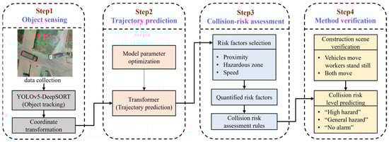
Figure 1.
Overall framework.
3.1. Object-Sensing Module (OSM)
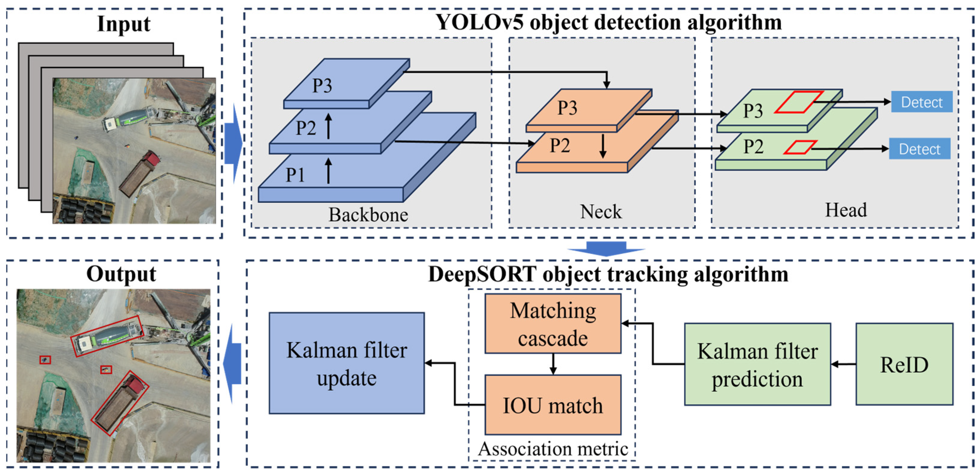
The YOLOv5-DeepSORT model is trained independently for the object detection and object tracking. Object detection is performed using the YOLOv5 algorithm [51]. Similarly, object tracking is accomplished by the DeepSORT algorithm [52]. The structure of YOLOv5-DeepSORT is presented in Figure 2.

Figure 2.
Structure of YOLOv5-DeepSORT. Adapted from [17].
3.1.1. Detection Branch
YOLOv5 is one of the most advanced object detection networks in the field of deep learning. It has been extensively validated and has demonstrated an excellent performance across various practical applications. YOLOv5 can be combined with DeepSORT to form the YOLOv5-DeepSORT object-tracking model, which shows a stronger performance. It has been widely used by researchers for object-tracking tasks. In this paper, the synergy between YOLOv5’s precise object detection and DeepSORT’s reliable tracking capabilities provides a solid foundation for trajectory prediction. The network architecture of YOLOv5 comprises three main components: Backbone, Neck, and Head. Herein, CSPDarknet53 [53] is used as a Backbone network, tasked with extracting features from the input images. In the Neck section, Spatial Pyramid Pooling (SPP) [54] and Path Aggregation Network (PAN) [55] are utilized for the multiscale fusion of features extracted in the previous steps. Lastly, the final prediction detection frame is generated by the Head component and is forwarded to the DeepSORT tracking algorithm.
3.1.2. Tracking Branch
DeepSORT is a multi-object-tracking algorithm, wherein eight variables are used to describe the states of tracked objects at a given moment, i.e., , where represents the center coordinates of the detection frame, represents the aspect ratio of the detection frame, represents the height of the detection frame, and represents the velocity information of the corresponding variables, i.e., .
In the tracking process, the Kalman filter [56] predicts the position of the next detection frame based on its current position and motion state. Subsequently, the Hungarian algorithm [57] is employed to match the detection frame with the tracking frame. The degree of match between the detection frame and the prediction frame is described using the Mahalanobis distance, as noted in Equation (1):
where represents detection frame position, represents tracking frame position, and represents the covariance matrix between the position of the detection frame and tracking frame.
If the Mahalanobis distance is less than the specified threshold , the correct match is considered to have been achieved, as noted in Equation (2):
3.1.3. Coordinate Transformation
Pixel coordinates of the workers and construction vehicles in the video were obtained by YOLOv5-DeepSORT object-tracking algorithms. The collision pre-warning model is required to determine the distances and speed information of workers and construction vehicles in the real world; therefore, it is necessary to convert pixel coordinates into real-world coordinates. In our study, real-world coordinates are calculated by assuming a proportional relationship between pixel coordinates and real-world coordinates [49]. Specifically, we use an Unmanned Aerial Vehicle (UAV) positioned 20 m above the ground level to vertically photograph a 10-meter-long truck. Comparing the truck’s length in the images with its actual length, we obtained the proportional relationship between the pixels and the real-world length. This method is shown to maintain an error margin within 0.5 m, as noted in Equation (3):
Among them, is the real-world coordinates, is the pixel coordinates, is the actual lengths of the objects, and is the measured lengths of the objects in the pictures.
3.2. Trajectory Prediction Module (TPM)
Transformer Model
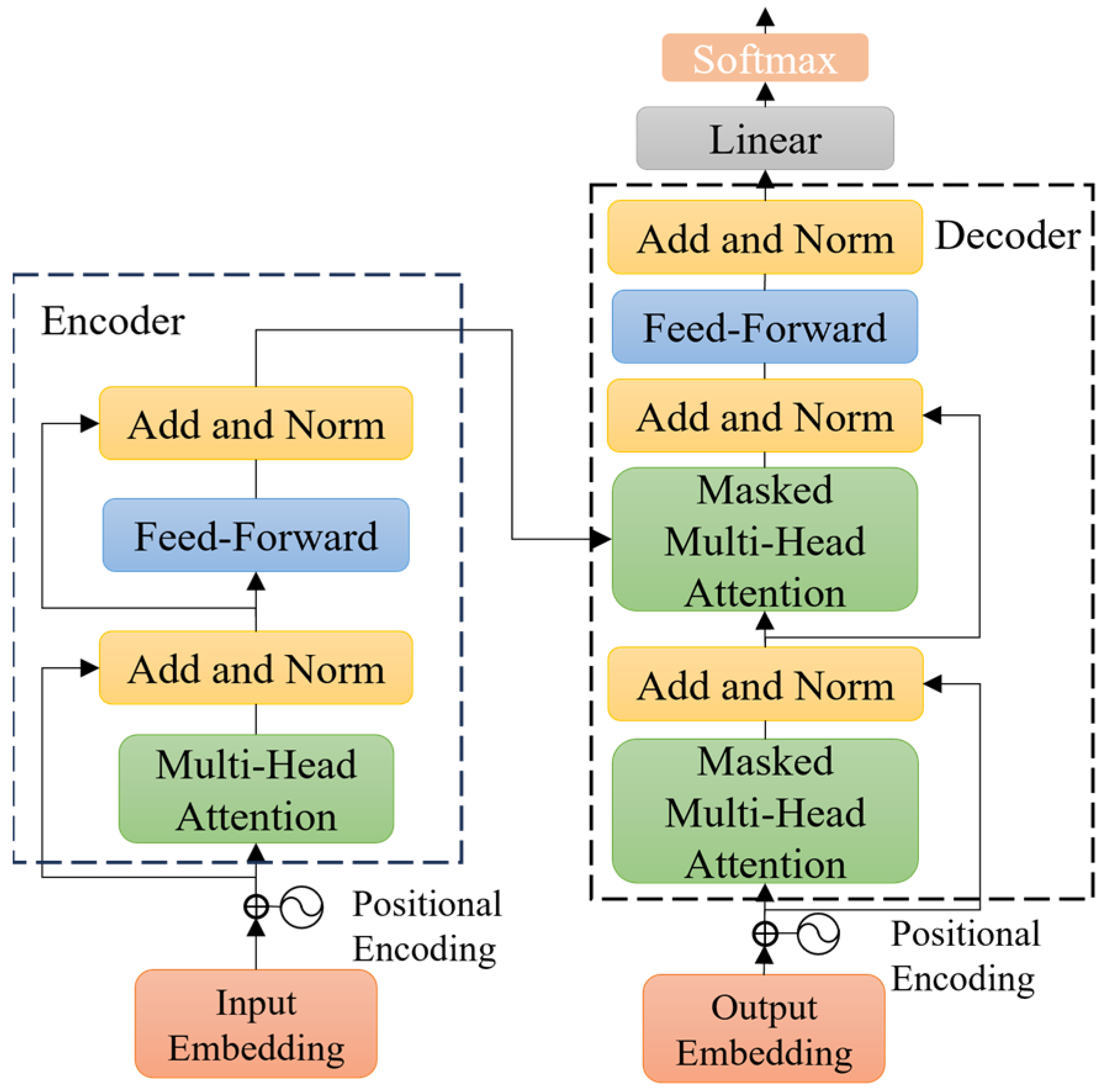
After obtaining the historical trajectories of the workers and construction vehicles, trajectory prediction is performed by a transformer model. The transformer model mainly includes three parts: positional encoding, encoder, and decoder. The network structure of the transformer model is presented in Figure 3.
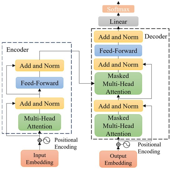
Figure 3.
Network structure of the transformer model. Adapted from [18].
Positional encoding is a special embedding used to provide models with information about the relative positions in input sequences. Position vector is added to the embedding vector using positional encoding, which incorporates ordinal features with sin and cos functions, as noted in Equations (4) and (5):
where represents positional encoding, is the position of the embedding vector in the sequence, and is the dimension of the embedding vector.
The encoder encodes input vectors into feature vectors. It consists of a multiple encoder layer, which separately contains two types of network layers: a self-attention layer and a feed-forward layer.
The decoder decodes the feature vector output from the encoder along with the input. Compared to the encoder, the decoder includes a masked multi-head attention layer. Masking means that certain input values are ignored, ensuring that they have no effects when the parameters are updated.
Self-attention mechanism is the core module of the transformer model, which is used to quantify the dependence of time series data. The self-attention mechanism takes the dimensions of Queries matrix , Key matrix , Value matrix , and dimension of Key matrix as input, as noted in Equation (6):
3.3. Collision-Risk Assessment Module (CRAM)
In our work, trucks, which are the most common construction vehicles on sites and which pose significant safety risks [58], are employed to explain our rules. A truck, 10 m long, 2.5 m wide, and 4.0 m high, serves as a representative construction vehicle to illustrate the process of quantifying hazardous zones, proximity, and speed factors.
- (a)
- When workers approach construction vehicles, they face the risk of being struck. Therefore, it is necessary to define the hazardous zones of the trucks to aid in safety determination. In this paper, the hazardous zones consist of two areas: blind spot areas and warning areas. Blind spot areas of the construction vehicles vary depending on the factors, such as the vehicle types and real-time motion directions (e.g., left turn, right turn, or straight ahead). Dynamically adjusting these blind spots using computer vision techniques poses significant challenges. This study initially employs a rectangular bounding box to simulate the hazardous zones of construction vehicles with greater accuracy. The main reason of using rectangular shapes is that most construction vehicles have a rectangular form. Thus, this method is more representative of the actual hazardous areas associated with construction vehicles. We define blind spots as rectangular areas around the truck’s detection frame, extending 2.5 m [59]. In addition, the truck’s warning areas are defined as a rectangular area extending 6.3 m around its detection frame [60]. Warning areas indicate the space where workers conduct activities near the construction vehicles (e.g., loading and unloading goods, guiding construction vehicles). However, workers in this area are not in any immediate danger, but they would remain highly vigilant.
- (b)
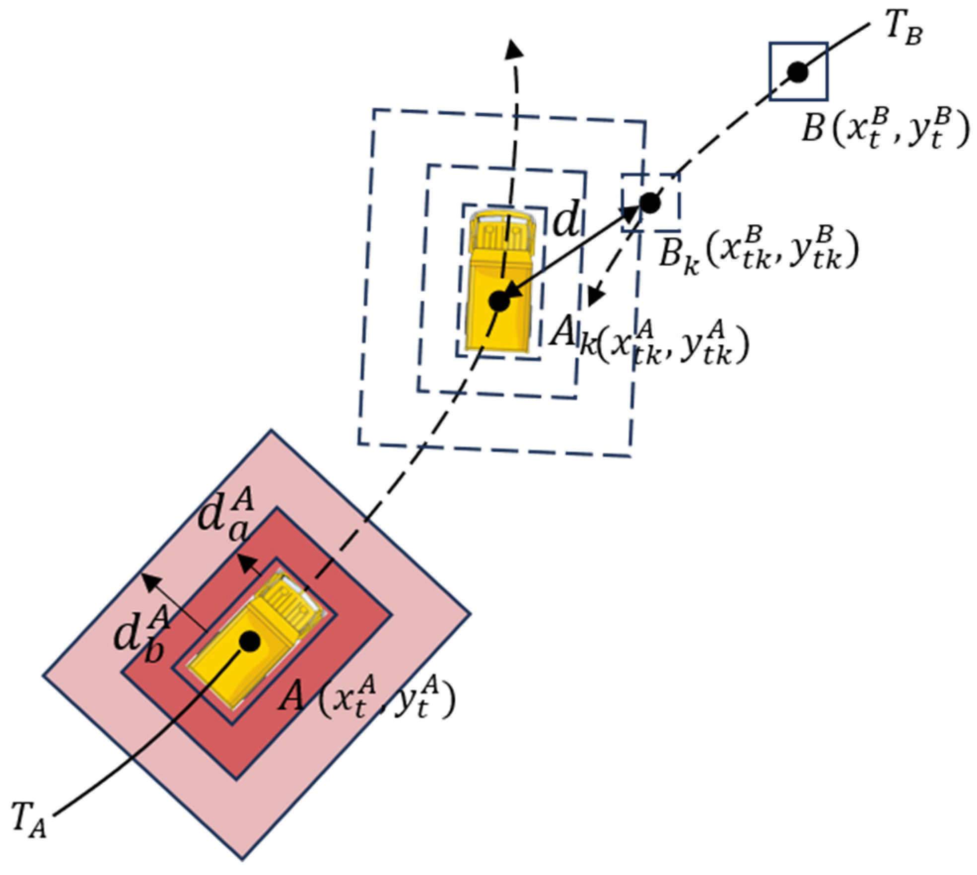
- Proximity relates to the distance between a worker and a construction vehicle, with closer proximity increasing the likelihood of injuries. At first, this study calculates Euclidean distance between the workers and pixel center points of the construction vehicles. Secondly, it estimates the actual distance between the workers and construction vehicles using the coordinate transformation given by Equation (3). As shown in Figure 4, in a Cartesian coordinate system, and represent the rectangular center points of the trucks and workers, respectively; and represent the trajectories of the trucks and workers, respectively. The solid line part is the historical trajectory, and the dotted line part is the predicted trajectory based on the historical trajectory. and , respectively, represent the distances between the truck’s rectangular detection frames and truck’s blind areas and warning areas. The space occupied by workers is represented by rectangular detection frames centered on point .
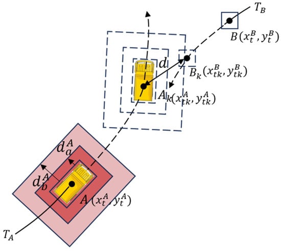 Figure 4. Quantitative risk factors based on trajectory prediction.
At time , worker meets the warning areas of truck , and the distance between the center points of the worker and truck is calculated using Equation (7):
where and represent coordinate positions of center points of truck and worker at time, respectively. However, the collision occurs due to the contact between the worker and the surface of the truck, so it needs to be converted to surface distance between two objects since the distance between the center of the truck and its surrounding surface is not fixed. This paper uses the average of the longest and shortest distance between the center of the truck and its surface as the distance between the center of truck and the surface. We apply a detection rectangle frame of the truck to approximate the surface around the truck. The truck is known to have a length of 10 m and a width of 2.5 m; it is thus easy to determine that the longest distance between the center point and the rectangle detection frame is about 5.15 m, and the shortest distance is 1.25 m. is the distance between the center of the truck and its surface, which is 3.2 m. The surface distance between the worker and the truck is calculated using Equation (8):
When is less than the set threshold of 6.3 m, it is judged that the workers have entered the warning areas. This method is also applicable to judge whether the workers have entered the blind spot areas of the trucks.
- (c)
- Speed is the movement speed of workers and construction vehicles, with higher speed correlating with more severe collisions. The speed limit of construction vehicles at the construction sites can be determined by local safety regulations. This study, by referring to reference [15], limits the speed of construction vehicles at the construction sites to no more than 5 km/h (about 1.4 m/s). The quantitative speed factor is calculated using Equation (9):
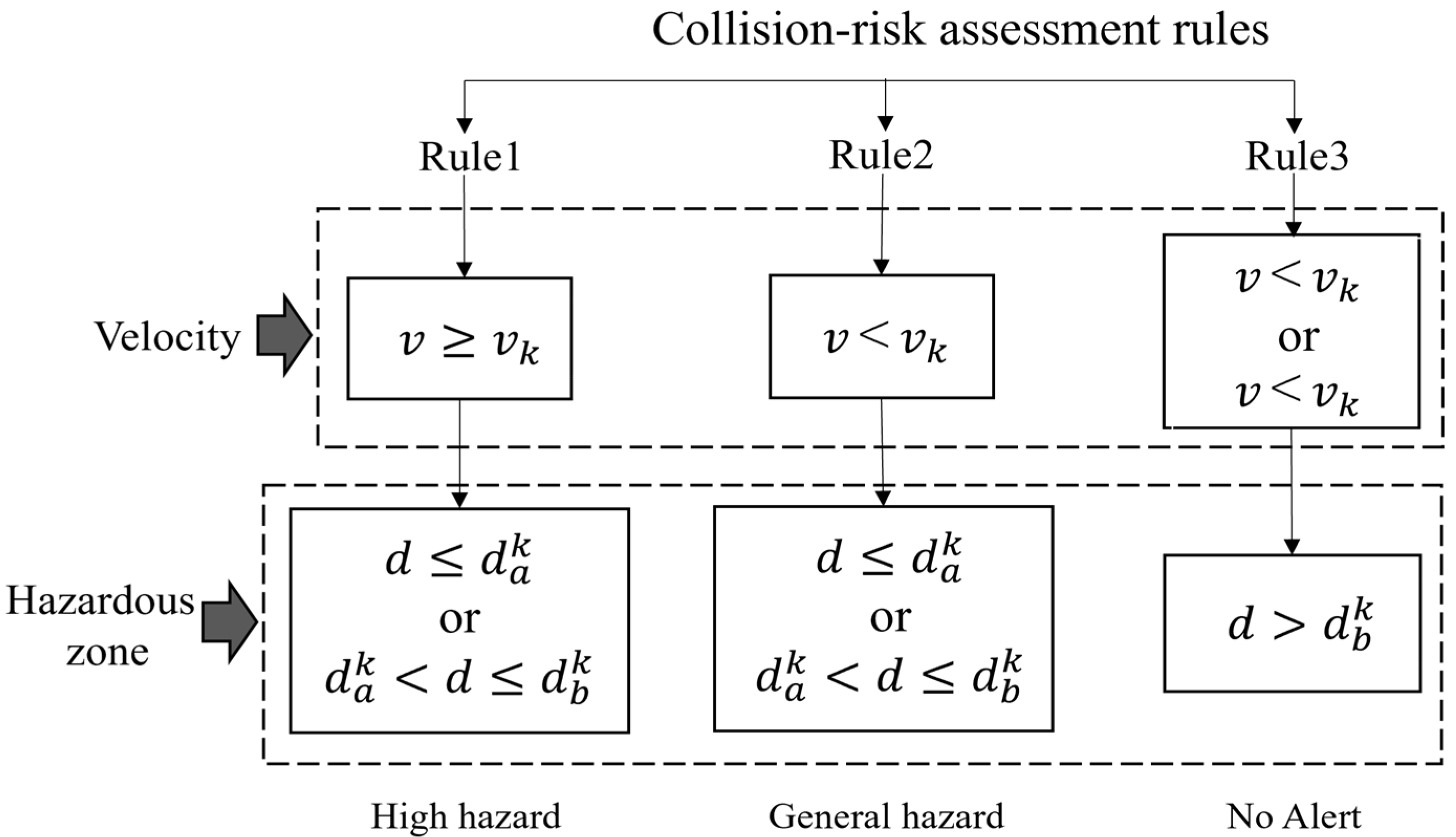
Considering the risk factors of hazardous zones, proximity, and speed, collision-risk assessment rules have been formulated. Based on these rules, the worker collision-risk level would be categorized into three levels: “high hazard”, “general hazard”, and “no alarm”. “High hazard” indicates that the workers are predicted to enter the blind spots or warning areas of a vehicle in the future, and the vehicles’ speed exceeds a predetermined threshold. In such situation, the workers are at risk, and even a minor mistake could result in an accident. “General hazard” denotes the situation in which the workers are expected to enter the blind spots or warning areas of vehicles in the future, but the vehicles’ speed remains lower than the set threshold. For example, when the workers need to work next to the vehicles, they are required to maintain a high level of concentration, and so the warning level is “general hazard” at this time. Lastly, “no alarm” indicates that there are no anticipated instances of the workers to enter the blind spots or warning areas of the vehicles in their future movement trajectories, rendering their working conditions as relatively safe. These rules are specifically shown in Figure 5. In the flowchart, represents the distance between the center point of the worker coordinates and the center point of the vehicle coordinates in a Cartesian coordinate system; represents the driving speed of trucks; represents the set blind spot areas threshold of trucks; represents the set warning area threshold of trucks; and represents the set speed threshold of construction vehicles.
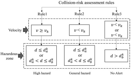
Figure 5.
Collision-risk assessment rules.
4. Experiment and Discussion
In this paper, the collision pre-warning model consists of object-tracking and trajectory prediction experiments. Firstly, object-tracking experiments are the performance tests of YOLOv5-DeepSORT in construction scenarios, and the trajectory prediction experiments include the optimization of transformer parameters and performance test experiments in construction scenarios. Finally, the effectiveness of the proposed method is verified by two different scenarios at construction sites. In terms of experimental platforms, the running memory was 16 GB, the graphics card model was GTX1660Ti, and the processor model was Intel Core i5-11400H CPU running at 4.50 GHz. The software environment was Ubuntu18.0 Linux, the training model framework was PyTorch, the batch size was set to 4, Adam was used as the optimizer, 500 epochs were trained for YOLOv5-DeepSORT, and 1000 epochs were trained for transformers.
4.1. Data Collection
To achieve a high-performance model, a substantial number of images of specific type are necessary. The algorithm in this paper encompasses both object-tracking and trajectory prediction; our group created datasets for each algorithm, separately. A total of 5514 objects were annotated in the object-tracking dataset: specifically, 2661 workers, 773 excavators, 721 trucks, and 1359 cement trucks. We applied data augmentation preprocessing to object-tracking dataset to ensure ample and high-quality data. For the trajectory prediction dataset, we conducted object tracking on a 15-minute and 52-second video of a construction site, resulting in 1322 trajectory coordinate points. All trajectory coordinate data were converted to real-world coordinates. Both datasets were divided into training and testing sets, with a division ratio of 9:1, as referenced by Zhang et al. [50].
4.1.1. Object-Tracking Dataset
We created an object tracking dataset by capturing aerial footage of construction sites using a DJI Phantom 4 drone equipped with an optical camera. The position information of construction vehicles and workers could be better observed with the vertically downward-facing cameras, facilitating the prediction of their trajectories. Due to the large size differences between construction vehicles and workers, an oblique shooting method could block workers behind construction vehicles, invalidating the subsequent prediction method. The footage was captured at a construction site in Wuhan, China, with a total duration of 26 minutes and 51 seconds. We extracted 5311 images by sampling every 10 frames from the video sequences. Each image was subsequently annotated using an open-source labeling tool LabelImg [61], annotating categories such as workers and three typical types of construction vehicles: trucks, excavators, and cement trucks. Annotations followed VOC format and were stored in XML files.
4.1.2. Trajectory Prediction Dataset
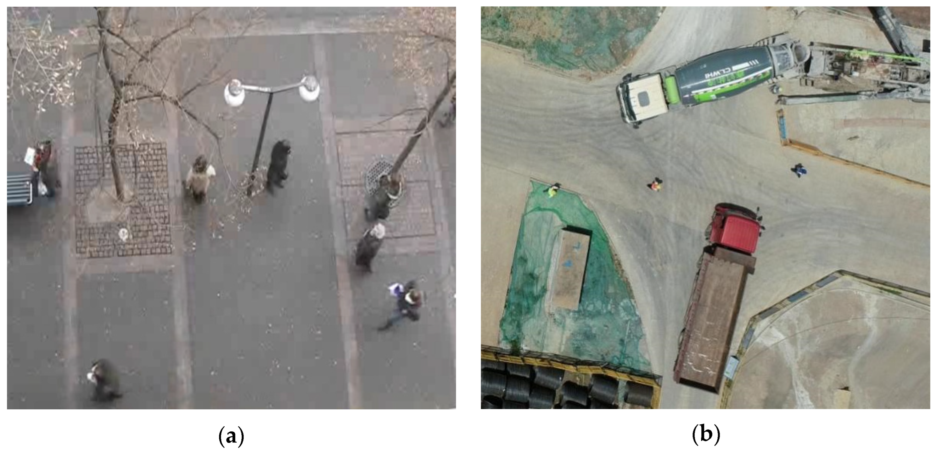
The trajectory prediction dataset used in this paper consists of two datasets from different sources. One is the public trajectory prediction dataset, such as ETH [62] and UCY [63]. These datasets are widely used in pedestrian trajectory prediction research. They contain interaction information among pedestrian trajectories and serve as the benchmark datasets for evaluating trajectory prediction algorithms, as shown in Figure 6a. ETH and UCY datasets contain five sub-datasets: Zara1, Zara2, UCY, Hotel, and Univ. Each sub-dataset consists of a series of track point data, including four pieces of information of the current video frame number, pedestrian ID, pedestrian’s x coordinates, and pedestrian’s y coordinates. Besides the public datasets, to enhance the applicability of trajectory prediction at construction sites, we created a self-made trajectory prediction dataset of construction sites, referring to the format of the public datasets ETH and UCY. Firstly, workers and construction vehicles in the construction site videos were recognized and tracked. Secondly, the coordinate center points of objects were transformed into real-world coordinates. Then, the data of the objects within the video frames were converted into text files for every 10 frames, where the information of the objects was in the same form as in the public datasets, including the current frame number, object ID, and coordinates (x, y) of objects. The images of the construction site dataset are shown in Figure 6b.
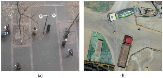
Figure 6.
Dataset images examples: (a) from public datasets; (b) from self-collected construction site images.
4.2. Experiment and Results of OSM
For accuracy evaluation, three indicators were used to evaluate the tracking performance of YOLOv5-DeepSORT: (1) Precision, which is the correct ratio of all predicted positive samples; (2) Recall, which is the number of the correctly predicted positive samples as a percentage of the numbers of the actual positive samples; and (3) Average Precision (AP), which is the integral of Precision over Recall, as noted in Equations (10)–(12):
where (true positive) signifies the accurate tracking of the worker or vehicle, (false positive) represents instances where the tracked object is different from the intended target, and (false negative) indicates the inability to track the worker or vehicle in the image.
Table 1 lists the results of object-tracking experiments. The average accuracy of both workers and three types of construction vehicles exceeds 95%, although the accuracy of workers is slightly lower compared to that of construction vehicles. This discrepancy might be attributed to the fact that, when viewed from an overhead perspective, workers occupy fewer pixels, resulting in occasional missed detections. Overall, the YOLOv5-DeepSORT model exhibits an exceptional performance, with an average accuracy of 98.7% across all classes. It is capable of accurately tracking workers and construction vehicles at construction sites.

Table 1.
Accuracy of YOLOv5-DeepSORT for tracking on the test dataset.
4.3. Experiment and Results of TPM
We used average displacement error (ADE) and final displacement error (FDE) as trajectory-prediction-accuracy evaluation indicators. ADE refers to the mean-squared error between the predicted coordinates and the actual coordinates in all time steps; FDE is the distance between the final predicted position and the final actual position , as noted in Equations (13) and (14):
4.3.1. Experiment of the Hyperparameter Optimization
This paper optimized the hyperparameters of the transformer models to enhance their feasibilities in predicting the trajectories of construction vehicles and workers at construction sites. The original models had the observation and prediction times set at 8 time steps (approximately 2.61 s) and 12 time steps (approximately 3.96 s), respectively. These adjustments ensure that prediction time allows workers sufficient time to take countermeasures when there is a tendency for them to collide with construction vehicles.
Previous research works have indicated that the average human reaction time was 0.627 s, and the average walking speed was 1.46 m per second [64]. Given a warning area size of 6.3 m, it should take approximately 4.942 s for a worker to exit the warning areas. Assuming an additional 1 s delay for the transmission of a pre-warning signal, the prediction time should be at least 5.942 s, which corresponds to roughly 18 time steps. As the worker’s prediction time step was determined, this paper considered 6 different observation time steps based on 18 prediction time steps, ranging from 6 time steps (approximately 1.98 s) to 16 time steps (approximately 5.94 s), with a 2 time step interval. The group with the highest accuracy was chosen as the optimal observation time to achieve the best prediction performance.
Table 2 presents the training accuracy results under the parameters of original models and different observation time steps with a prediction time step of 18. Increasing the observation time steps does not necessarily improve the trajectory prediction accuracy. Because the excessively long observation time can introduce noise or irrelevant trajectory information, this negatively impacts on model accuracy and stability. Consequently, this often leads to a decreased accuracy in the trajectory prediction, which is consistent with the study by Kim et al. [15]. The results demonstrate that, with the observation and prediction time steps set to 6 and 18, respectively, the average displacement error (ADE) is 0.57 m, and the final displacement error (FDE) is 1.12 m. The accuracy of trajectory prediction has reached its optimal level. Compared to the model’s original parameter settings, the average error is reduced by 23%. This indicates that the improved transformer model can more accurately predict the trajectories of workers and construction vehicles, thus enhancing the precision and reliability of collision predictions. Consequently, the prediction time step is set to 18, and the observation time step is set to 6 for applications in our work.
Table 2.
Accuracy of transformer on the test set with various parameters settings.
4.3.2. Comparison between Methods
To compare the performance of the transformer-based trajectory prediction model with previous models, this paper tested the trajectory prediction model on ETH + UCY and self-made datasets. The comparison results are shown in Table 3. It is found that the performance of the transformer-based trajectory prediction model is better than that of LSTM, social-LSTM, and social-GAN.
Table 3.
Results of comparison study on trajectory prediction.
4.4. Method Validation
The effectiveness of the collision pre-warning model proposed in this paper is verified by two different construction site scenarios. These scenarios may lead to collisions between the workers and construction vehicles, which are categorized into the situations when both the workers and construction vehicles are moving, and the situations when workers are stationary and construction vehicles are moving.
4.4.1. Scene 1
In Figure 7a, two hazardous zones of a truck are highlighted. The rectangular boxes , with a truck as the center point indicate the distances between the truck’s vision blind spot areas and warning areas and the truck’s detection frame, which are 2.5 m and 6.3 m, respectively. A worker label “worker1, 0.83, 1.51 m/s” indicates that the current detection object is a worker, the tracking ID is 1, the object detection confidence is 0.83, and the worker’s current speed is 1.51 m/s. The truck label “truck1, 0.92, 1.82 m/s” indicates that the current detection object is a truck, the tracking ID is 1, the object detection confidence is 0.92, and the truck’s current speed is 1.82 m/s. Historical and predicted trajectories of workers and trucks are represented by lines connecting differently colored coordinate points.
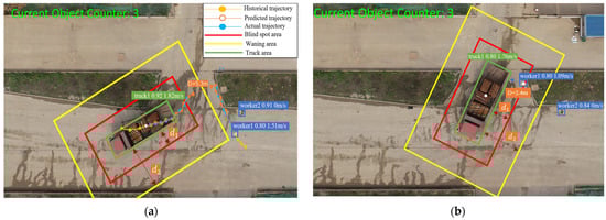
Figure 7.
Example of scene 1: (a) trajectory prediction of worker and truck under the present moment; (b) position of worker and truck after 6 s.
Based on the experimental results of the transformer parameter optimization, we set the observation and prediction time to 2 s and 6 s. To compare the predicted and actual future trajectories, we represent the predicted trajectories with hollow dots.
In Figure 7a, D represents the predicted distance between the worker and the center of the truck after 6 s, which is 5.3 m. However, it is necessary to subtract the mean distance between the truck’s center and its detection box (3.2 m) and the distance between the truck’s center and its surface (2.1 m). In Figure 7b, D represents the actual vertical distance between the center of worker 1 and the boundary of the truck after 6 s, which is 2.4 m. In Figure 7a, truck 1’s speed is 1.82 m/s, exceeding the predefined threshold of 1.4 m/s. The distance between worker 1 and truck 1 is 2.1 m, which is less than the visual field blindness threshold of 2.5 m. According to the safety risk assessment rules, these results indicate a high hazard warning level for worker 1. Worker 2 is stationary and does not enter the truck’s hazardous zones, so the warning level is “no alarm”.
4.4.2. Scene 2
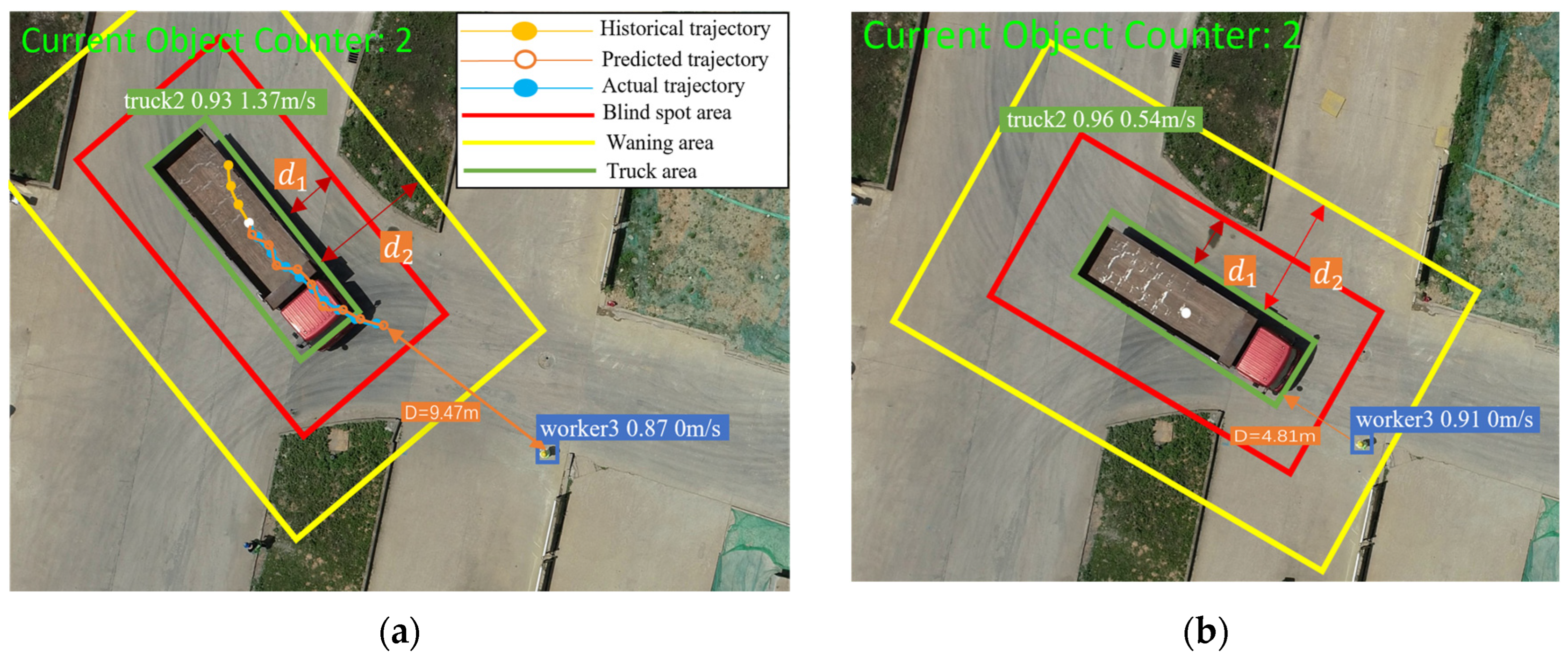
In this scene, as shown in Figure 8a, worker 3 remains stationary, and thus the velocity is 0. Truck 2 moves towards worker 3 at a velocity of 1.37 m/s. After 6 s of trajectory prediction, the distance between worker 3 and truck 2 at the center point is 9.47 m. Subtracting the mean distance from the center point to the detection box (3.2 m) results in 6.27 m. After 6 s, the detection frames of worker 3 and truck 2 intersect, as shown in Figure 8b. Worker 3 enters the warning areas of truck 2, which typically occurs when a worker is loading or unloading goods near a truck. In Figure 8a, the speed of truck 2 is 1.37 m/s, which is less than the set threshold of 1.4 m/s. The distance between worker 3 and truck 2 is 2.1 m, which is less than the warning area threshold of 2.5 m. Therefore, the warning level of worker 3 is ‘general hazard’.
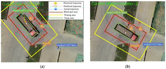
Figure 8.
Example of scene 2: (a) trajectory prediction of worker and truck under the current moment; (b) position of worker and truck after 6 s.
4.4.3. Summary
Validation of the trajectory prediction and collision-risk assessment rules is performed through two different scenarios at a realistic construction site. For the target tracking, YOLOv5-DeepSORT performs well, accurately identifying and tracking workers and construction vehicles. Regarding to trajectory prediction, the predicted trajectories closely match the actual future trajectories, indicating good prediction results, as shown in Figure 6a. Scenarios 1 and 2 validate some of the rules in the proposed worker safety risk assessment and are consistent with the actual construction site conditions. However, the scenarios reveal some limitations of the method. In predicting the trajectories of workers and construction vehicles, there is some discrepancy between the predicted and actual distances. There are some errors of accuracy in the transformer model. For instance, the average value is used to approximate the distance from the center of the truck to its boundary. Nevertheless, the error remains within an acceptable range.
5. Conclusions
Collisions between workers and construction vehicles have been a major cause of worker injuries and fatalities. This paper proposes a three-stage collision-risk pre-warning model for workers and construction vehicles in construction sites. The model consists of three modules: (1) object-sensing module (OSM), which uses YOLOv5-DeepSORT to identify and track workers and construction vehicles, obtaining their real-time locations and historical trajectories; (2) trajectory prediction module (TPM), which uses an improved transformer model with optimized parameters to predict the future trajectories of workers and construction vehicles, reducing the average error of accuracy by 23% compared to the original models and extending the prediction horizon to give workers more time to take preventive measures; and (3) collision-risk assessment module (CRAM), in which we propose a hierarchical worker collision-risk assessment rule, assessing risks using a multi-factor approach considering velocity, hazardous zones, and proximity. The effectiveness of the collision pre-warning model is validated through two different scenarios at construction sites. The results demonstrate that the proposed collision pre-warning model can accurately predict the collision-risk level of workers at construction sites, with effective tracking, prediction, and collision-risk pre-warning strategies.
In addition to contributions, there are some limitations that present potential future research directions. Firstly, diverse types of construction scenarios should be used to comprehensively evaluate the robustness of the proposed model. Secondly, in this paper, the blind spots and warning areas of construction vehicles are approximately expressed as fixed rectangular areas around the construction vehicles. However, dynamically changing hazardous zones of construction vehicles, types, and the speeds of vehicles, surrounding objects, the terrain, etc., are more rational and faithful to the real environment of construction sites, and will contribute to more accurate collision pre-waring decision-making [65,66]. Additionally, the collision pre-warning model proposed in this study integrates various advanced CV technologies and deep learning algorithms. The availability of computational resources should be considered for application to the model. Therefore, end-to-end lightweight models will be valuable topics for future research studies. Finally, since our work focuses on the collisions between vehicles and workers at construction sites, users should adjust the parameters when applying the model to other scenarios.
Author Contributions
Conceptualization, W.G.; methodology, J.G.; software, C.Q.; validation, H.W.; investigation, K.G.; resources, J.G.; data curation, K.G.; writing—original draft preparation, C.Q.; writing—review and editing, X.H.; visualization, R.Y.; supervision, X.H.; project administration, W.G. All authors have read and agreed to the published version of the manuscript.
Funding
The work is supported by National Natural Science Foundation of China (No. 42201461) and The Science Foundation of the Department of Transport of Hubei Province (No. 2023-121-3-4).
Data Availability Statement
The raw data supporting the conclusions of this article will be made available by the authors on request.
Conflicts of Interest
The authors declare no conflicts of interest.
References
- Love, P.E.D.; Teo, P.; Morrison, J. Unearthing the nature and interplay of quality and safety in construction projects: An empirical study. Saf. Sci. 2018, 103, 270–279. [Google Scholar] [CrossRef]
- Fang, W.; Love, P.E.; Luo, H.; Ding, L. Computer vision for behaviour-based safety in construction: A review and future directions. Adv. Eng. Inform. 2020, 43, 100980. [Google Scholar] [CrossRef]
- Bureau of Labor Statistics. Census of Fatal Occupational Injuries Summary, 2021 (USDL-20–2265); Bureau of Labor Statistics: Washington, DC, USA, 2022. [Google Scholar]
- Wang, Y.; Ma, L.; Zhang, P.; Fang, D. Evaluation and improvement of owner’s safety management behavior based on LCB theory. China Civ. Eng. J. 2021, 54, 117–124. [Google Scholar]
- The U.S. Occupational Safety and Health Administration (OSHA); OSHA Construction Etools: Washington, DC, USA, 2013. [Google Scholar]
- Ministry of Housing and Urban-Rural Development of the People’s Republic of China. Available online: https://www.mohurd.gov.cn/gongkai/zhengce/zhengcefilelib/202210/20221026_768565.Html2020 (accessed on 27 April 2023).
- Yu, Y.; Guo, H.; Ding, Q.; Li, H.; Skitmore, M. An experimental study of real-time identification of construction workers’ unsafe behaviors. Autom. Constr. 2017, 82, 193–206. [Google Scholar] [CrossRef]
- Zhang, M.; Shi, R.; Yang, Z. A critical review of vision-based occupational health and safety monitoring of construction site workers. Saf. Sci. 2020, 126, 104658. [Google Scholar] [CrossRef]
- Pradhananga, N.; Teizer, J. Automatic spatio-temporal analysis of construction site equipment operations using GPS data. Autom. Constr. 2013, 29, 107–122. [Google Scholar] [CrossRef]
- Baek, J.; Choi, Y. Bluetooth-beacon-based underground proximity warning system for preventing collisions inside tunnels. Appl. Sci. 2018, 8, 2271. [Google Scholar] [CrossRef]
- Fang, D.; Wu, H. Development of a safety culture interaction (SCI) model for construction projects. Saf. Sci. 2013, 57, 138–149. [Google Scholar] [CrossRef]
- Xu, W.; Wang, T.K. Dynamic safety prewarning mechanism of human–machine–environment using computer vision. Eng. Constr. Archit. Manag. 2020, 27, 1813–1833. [Google Scholar] [CrossRef]
- Anwar, Q.; Hanif, M.; Shimotoku, D.; Kobayashi, H.H. Driver awareness collision/proximity detection system for heavy vehicles based on deep neural network. J. Phys. Conf. Ser. 2022, 2330, 012001. [Google Scholar] [CrossRef]
- Han, S.; Lee, S.; Al-Hussein, M. Computer vision-based approach to the automation of scaffolding construction: With image data using deep learning. J. Constr. Eng. Manag. 2017, 143, 04017012. [Google Scholar]
- Kim, D.; Liu, M.; Lee, S.; Kamat, V.R. Trajectory prediction of mobile construction resources toward pro-active struck-by hazard detection. In Proceedings of the International Symposium on Automation Robotics in Construction (IAARC), Banff, AB, Canada, 21–24 May 2019. [Google Scholar]
- Wang, J.; Razavi, S. Spatiotemporal network-based model for dynamic risk analysis on struck-by-equipment hazard. J. Comput. Civ. Eng. 2018, 32, 04017089. [Google Scholar] [CrossRef]
- Gai, Y.; He, W.; Zhou, Z. Pedestrian target tracking based on DeepSORT with YOLOv5. In Proceedings of the 2021 2nd International Conference on Computer Engineering and Intelligent Control (ICCEIC), Chongqing, China, 12–14 November 2021; pp. 1–5. [Google Scholar]
- Vaswani A, Shazeer N, Parmar N; Uszkoreit, J.; Jone, L.; Gomez, A.; Kaiser, L.; Polosukhin, I. Attention is all you need. Adv. Neural Inf. Process. Syst. 2017, arXiv:1706.03762. [CrossRef]
- Zhu, Z.; Ren, X.; Chen, Z. Visual tracking of construction objsite workforce and equipment with particle filtering. J. Comput. Civ. Eng. 2016, 30, 04016023. [Google Scholar] [CrossRef]
- Park, M.W.; Makhmalbaf, A.; Brilakis, I. Comparative study of vision tracking methods for tracking of construction site resources. Autom. Constr. 2011, 20, 905–915. [Google Scholar] [CrossRef]
- Luo, X.; Li, H.; Wang, H.; Wu, Z.; Dai, F.; Cao, D. Vision-based detection and visualization of dynamic workspaces. Autom. Constr. 2019, 104, 1–13. [Google Scholar] [CrossRef]
- Bügler, M.; Borrmann, A.; Ogunmakin, G.; Teizer, V. Fusion of photogrammetry and video analysis for productivity assessment of earthwork processes. Comput.-Aided Civ. Infrastruct. Eng. 2017, 32, 107–123. [Google Scholar] [CrossRef]
- Bayraktar, E.; Basarkan, M.E.; Celebi, N. A low-cost UAV framework towards ornamental plant detection and counting in the wild. ISPRS J. Photogramm. Remote Sens. 2020, 167, 1–11. [Google Scholar] [CrossRef]
- Suljagic, H.; Bayraktar, E.; Celebi, N. Similarity based person re-identification for multi-object tracking using deep Siamese network. Neural Comput. Appl. 2022, 34, 18171–18182. [Google Scholar] [CrossRef]
- Bayraktar, E.; Wang, Y.; DelBue, A. Fast re-OBJ: Real-time object re-identification in rigid scenes. Mach. Vis. Appl. 2022, 33, 97. [Google Scholar] [CrossRef]
- Bayraktar, E.; Korkmaz, B.N.; Erarslan, A.U.; Celebi, N. Traffic congestion-aware graph-based vehicle rerouting framework from aerial imagery. Eng. Appl. Artif. Intell. 2023, 119, 105769. [Google Scholar] [CrossRef]
- Zhang, Y.; Wang, C.; Wang, X.; Zeng, W.; Liu, W. Fairmot: On the fairness of detection and re-identification in multiple object tracking. Int. J. Comput. Vis. 2021, 129, 3069–3087. [Google Scholar] [CrossRef]
- Zhou, X.; Koltun, V.; Krähenbühl, P. Tracking objects as points. In Proceedings of the European Conference on Computer Vision, Glasgow, UK, 23–28 August 2020; pp. 474–490. [Google Scholar]
- Sridhar, V.H.; Roche, D.G.; Gingins, S. Tracktor: Image-based automated tracking of animal movement and behaviour. Methods Ecol. Evol. 2019, 10, 815–820. [Google Scholar] [CrossRef]
- Wu, S.; Hou, L.; Zhang, G.K.; Chen, H. Real-time mixed reality-based visual warning for construction workforce safety. Autom. Constr. 2022, 139, 104252. [Google Scholar] [CrossRef]
- Razzok, M.; Badri, A.; El Mourabit, I.; Ruichek, Y.; Sahel, A. Pedestrian Detection and Tracking System Based on Deep-SORT, YOLOv5, and New Data Association Metrics. Information 2023, 14, 218. [Google Scholar] [CrossRef]
- Altché, F.; de La Fortelle, A. An LSTM network for highway trajectory prediction. In Proceedings of the 2017 IEEE 20th International Conference on Intelligent Transportation Systems (ITSC), Yokohama, Japan, 16–19 October 2017; pp. 353–359. [Google Scholar]
- Bennewitz, M.; Burgard, W.; Cielniak, G.; Thrun, S. Learning motion patterns of people for compliant robot motion. Int. J. Robot. Res. 2005, 24, 31–48. [Google Scholar] [CrossRef]
- Kitani, K.M.; Okabe, T.; Sato, Y.; Sugimoto, A. Fast unsupervised ego-action learning for first-person sports videos. In Proceedings of the 24th IEEE Conference on Computer Vision and Pattern Recognition, CVPR 2011, Colorado Springs, CO, USA, 20–25 June 2011. [Google Scholar]
- Kooij, J.F.P.; Flohr, F.; Pool, E.A.I.; Gavrila, D.M. Context-based path prediction for targets with switching dynamics. Int. J. Comput. Vis. 2019, 127, 239–262. [Google Scholar] [CrossRef]
- Williams, C.K.I. Prediction with Gaussian Processes: From Linear Regression to Linear Prediction and Beyond. Learning in Graphical Models; Springer: Dordrecht, The Netherlands, 1998; pp. 599–621. [Google Scholar]
- Becker, S.; Hug, R.; Hubner, W.; Arens, M. Red: A simple but effective baseline predictor for the trajnet benchmark. In Proceedings of the European Conference on Computer Vision (ECCV) Workshops, Munich, Germany, 8–14 September 2018. [Google Scholar]
- Alahi, A.; Goel, K.; Ramanathan, V.; Robicquet, A.; Li, F.F.; Savarese, S. Social lstm: Human trajectory prediction in crowded spaces. In Proceedings of the IEEE Conference on Computer Vision and Pattern Recognition, Las Vegas, NV, USA, 27–30 June 2016; pp. 961–971. [Google Scholar]
- Xue, H.; Huynh, D.Q.; Reynolds, M. SS-LSTM: A hierarchical LSTM model for pedestrian trajectory prediction. In Proceedings of the 2018 IEEE Winter Conference on Applications of Computer Vision (WACV), Lake Tahoe, NV, USA, 12–18 March 2018; pp. 1186–1194. [Google Scholar]
- Zhou, H.; Zhang, S.; Peng, J.; Zhang, S.; Li, J.; Xiong, H.; Zhang, W. Informer: Beyond efficient transformer for long sequence time-series forecasting. In Proceedings of the AAAI Conference on Artificial Intelligence 2021, Palo Alto, CA, USA, 2–9 February 2021; Volume 35, pp. 11106–11115. [Google Scholar]
- Giuliari, F.; Hasan, I.; Cristani, M.; Galasso, F. Transformer networks for trajectory forecasting. In Proceedings of the 2020 25th International Conference on Pattern Recognition (ICPR), Milan, Italy, 10–15 January 2021; pp. 10335–10342. [Google Scholar]
- Devlin, J.; Chang, M.W.; Lee, K.; Toutanova, K. Bert: Pre-training of deep bidirectional transformers for language understanding. arXiv 2018, arXiv:1810.04805. [Google Scholar]
- Haslam, R.A.; Hide, S.A.; Gibb, A.G.; Gyi, D.E.; Pavitt, T.; Atkinson, S.; Duff, A.R. Contributing factors in construction accidents. Appl. Ergon. 2005, 36, 401–415. [Google Scholar] [CrossRef]
- NIOSH (National Institute for Occupational Safety and Health). Fatality Assessment and Control Evaluation (FACE) Program. 2016. Available online: https://www.cdc.gov/niosh/face/ (accessed on 18 April 2016).
- Wang, J.; Razavi, S. Network-based safety leading indicators for safety risk analysis in construction. In Proceedings of the Human Factors and Ergonomics Society Annual Meeting, Seattle, WA, USA, 8 October–1 November 2019; Volume 63, pp. 1787–1791. [Google Scholar]
- Wang, J.; Razavi, S. Two 4D models effective in reducing false alarms for struck-by-equipment hazard prevention. J. Comput. Civ. Eng. 2016, 30, 04016031. [Google Scholar] [CrossRef]
- Du, S.; Shehata, M.; Badawy, W. Hard hat detection in video sequences based on face features, motion and color information. In Proceedings of the 2011 3rd International Conference on Computer Research and Development, Shanghai, China, 11–13 March 2011; Volume 4, pp. 25–29. [Google Scholar]
- Ferrer, B.; Pomares, J.C.; Irles, R.; Espinosa, J.; Mas, D. Image processing for safety assessment in civil engineering. Appl. Opt. 2013, 52, 4385–4390. [Google Scholar] [CrossRef] [PubMed]
- Yang, Z.; Yuan, Y.; Zhang, M.; Zhao, X.; Zhang, Y.; Tian, B. Safety distance identification for crane drivers based on mask R-CNN. Sensors 2019, 19, 2789. [Google Scholar] [CrossRef] [PubMed]
- Zhang, M.; Ge, S. Vision and trajectory–Based dynamic collision prediction mechanism for tower cranes. J. Constr. Eng. Manag. 2022, 148, 04022057. [Google Scholar] [CrossRef]
- Redmon, J.; Divvala, S.; Girshick, R.; Farhadi, A. You only look once: Unified, real-time object detection. In Proceedings of the IEEE Conference on Computer Vision and Pattern Recognition, Las Vegas, NV, USA, 27–30 June 2016; pp. 779–788. [Google Scholar]
- Wojke, N.; Bewley, A.; Paulus, D. Simple online and realtime tracking with a deep association metric. In Proceedings of the 2017 IEEE International Conference on Image Processing (ICIP), Beijing, China, 17–20 September 2017; pp. 3645–3649. [Google Scholar]
- Mahasin, M.; Dewi, I.A. Comparison of CSPDarkNet53, CSPResNeXt-50, and EfficientNet-B0 Backbones on YOLO V4 as Object Detector. Int. J. Eng. Sci. Inf. Technol. 2022, 2, 64–72. [Google Scholar]
- He, K.; Zhang, X.; Ren, S.; Sun, J. Spatial pyramid pooling in deep convolutional networks for visual recognition. IEEE Trans. Pattern Anal. Mach. Intell. 2015, 37, 1904–1916. [Google Scholar] [CrossRef] [PubMed]
- Liu, S.; Qi, L.; Qin, H.; Shi, J.; Jia, J. Path aggregation network for instance segmentation. In Proceedings of the IEEE Conference on Computer Vision and Pattern Recognition, Salt Lake City, UT, USA, 18–23 June 2018; pp. 8759–8768. [Google Scholar]
- Kalman, R.E. A new approach to linear filtering and prediction problems. J. Basic Eng. 1960, 82, 35–45. [Google Scholar]
- Kuhn, H.W. The Hungarian method for the assignment problem. Nav. Res. Logist. Q. 1955, 2, 83–97. [Google Scholar] [CrossRef]
- Zhang, R.; Liu, J.; Ma, L. A typical blind spot danger pre-warning method of heavy truck under turning right condition. In Proceedings of the 2015 Sixth International Conference on Intelligent Systems Design and Engineering Applications (ISDEA), Guiyang, China, 18–19 August 2015; pp. 93–96. [Google Scholar]
- Seiniger, P.; Gail, J.; Schreck, B. A draft regulation for driver assist systems addressing truck-cyclist blind spot accidents. In Proceedings of the 25th international technical conference on the Enhanced Safety of Vehicles (ESV), Detroit Michigan, MI, USA, 6 June 2017. [Google Scholar]
- Shen, X. Location-Based Leading Indicators in BIM for Construction Safety; University of Alabama Libraries: Tuscaloosa, AL, USA, 2017. [Google Scholar]
- Yakovlev, A.; Lisovychenko, O. An approach for image annotation automatization for artificial intelligence models learning. Adapt. Autom. Steer. Syst. 2020, 1, 32–40. [Google Scholar]
- Pellegrini, S.; Ess, A.; Van Gool, L. Improving data association by joint modeling of pedestrian trajectories and groupings. In Proceedings of the Computer Vision–ECCV 2010: 11th European Conference on Computer Vision, Heraklion, Crete, Greece, 5–11 September 2010; Proceedings, Part I 11. Springer: Berlin/Heidelberg, Germany, 2010; pp. 452–465. [Google Scholar]
- Leal-Taixé, L.; Fenzi, M.; Kuznetsova, A.; Rosenhahn, B.; Savarese, S. Learning an image-based motion context for multiple people tracking. In Proceedings of the IEEE Conference on Computer Vision and Pattern Recognition, Columbus, OH, USA, 23–28 June 2014; pp. 3542–3549. [Google Scholar]
- Theios, J. Reaction time measurements in the study of memory processes: Theory and data. In Psychology of Learning and Motivation; Academic Press: Cambridge, MA, USA, 1973; Volume 7, pp. 43–85. [Google Scholar]
- Golovina, O.; Teizer, J.; Pradhananga, N. Heat map generation for predictive safety planning: Preventing struck-by and near miss interactions between workers-on-foot and construction equipment. Autom. Constr. 2016, 71, 99–115. [Google Scholar]
- Son, H.; Seong, H.; Choi, H.; Kim, C. Real-time vision-based warning system for prevention of collisions between workers and heavy equipment. J. Comput. Civ. Eng. 2019, 33, 04019029. [Google Scholar] [CrossRef]


Disclaimer/Publisher’s Note: The statements, opinions and data contained in all publications are solely those of the individual author(s) and contributor(s) and not of MDPI and/or the editor(s). MDPI and/or the editor(s) disclaim responsibility for any injury to people or property resulting from any ideas, methods, instructions or products referred to in the content. |
© 2024 by the authors. Licensee MDPI, Basel, Switzerland. This article is an open access article distributed under the terms and conditions of the Creative Commons Attribution (CC BY) license (https://creativecommons.org/licenses/by/4.0/).