Article

Evaluation of TBM Cutter Wear in Granite and Developing a Cutter Life Prediction Model for Face Cutters Based on Field Data: A Case Study

by
Jianping Liu
1,*,
Tiankui He
1,
Xingxin Peng
2 and
Yucong Pan
3
1
College of Water Conservancy and Hydropower Engineering, Sichuan Agricultural University, Ya’an 625014, China
2
China Railway 11th Bureau Group Fourth Engineering Co., Ltd., Wuhan 430074, China
3
School of Civil Engineering, Wuhan University, Wuhan 430072, China
*
Author to whom correspondence should be addressed.
Buildings 2024, 14(8), 2453; https://doi.org/10.3390/buildings14082453
Submission received: 7 June 2024 / Revised: 12 July 2024 / Accepted: 7 August 2024 / Published: 8 August 2024
(This article belongs to the Section Building Energy, Physics, Environment, and Systems)

Abstract

:
Disc cutter wear has emerged as a critical concern impacting the efficiency and cost budgets of TBMs (tunnel boring machines). Through statistical analysis of field data on cutter wear in a TBM tunnel, this study explores the wear rules of different types of disc cutters in granite. Grey sensitivity analysis is employed to investigate the sensitivity between the cutter ring wear rate of face cutters and two types of cutter wear influence parameters. Subsequently, reasonable parameters are selected to develop a new cutter life prediction model for face cutters. The results show that, with increases in the installation radius, the accumulated wear extent shows a linearly increasing trend for both the center and the face cutter, while it first increases and then decreases for gauge cutters, and the accumulated replacement number shows a linear growth trend for face cutters. The accumulated wear extent of the average single cutter position of gauge cutters is about 3 times that of face cutters and 7 times that of center cutters; the number of replaced cutter rings of the average single cutter position for gauge cutters is about 3–4 times that for center cutters and face cutters; and the average utilization rate of gauge cutters is the highest (80.97%). The cutter ring wear rate of face cutters is the most sensitive to three intact rock parameters (uniaxial compressive strength (UCS), Cerchar abrasion index (CAI), and equivalent quartz content (EQC)) and two TBM tunnelling parameters (cutterhead thrust (F) and cutterhead rotational speed (RPM)). Finally, a new cutter life prediction model (R2 = 0.964) for face cutters is developed based on F, UCS, and RPM. The research results can provide a certain theoretical basis for cutter wear and cutter life prediction for the face cutters of TBM projects in similar geological conditions and TBM specifications.

1. Introduction

With the rapid development of China’s national economy, it is urgent to build a large number of long-distance tunnels for water conservancy, transportation, mining, and other fields, and tunnel boring machines (TBMs) are now widely used for long-distance tunnel construction [1,2,3,4,5,6,7,8,9,10,11,12,13,14]. Disc cutters, located at the front of TBM cutterheads, invade and break rock after a series of complex interactions with the surrounding rock of the tunnel face [15,16,17,18]. Cutter wear is an inevitable result due to the high strength and high abrasiveness of rock, which becomes an unavoidable major problem in TBM tunneling and seriously affects construction schedules and costs [19,20,21,22,23]. Cutter inspectors need to accurately measure the current cutter wear extent and replace the cutters that have worn to the limit or have apparent abnormal wear in a timely manner [24,25,26,27,28]. The daily inspection and replacement of disc cutters is an extremely complex and time-consuming process [29,30,31,32]. At present, establishing a rock–machine interaction database can provide a new approach to solving the above problems. Not only can the wear rules of cutters be explored through a large amount of field data, but also a cutter life prediction model can be established on this basis to achieve real-time evaluation of the cutter life status, providing guidance for safe and efficient TBM excavation. Hence, it has become a hot research problem to explore cutter wear and develop a cutter life prediction model.
As cutter wear can only be intuitively reflected after a long time of cutter and rock interaction, most of the existing studies on cutter wear carry out statistical analysis of field data. For example, Geng et al. [33] studied the influence of layout on the consumption of face cutters based on the field data of six tunnels. Liu et al. [3] analyzed the variation in the cumulative wear of cutter rings and the number of cutter ring replacements with the installation radius based on the field data of one tunnel. Yang et al. [34] analyzed the damage and consumption law and its reasons based on the field data of one tunnel. Zhou et al. [35] revealed a cutter wear rule under high-strength (average strength of 120 MPa) conditions based on a case study. Shi et al. [36] proposed an ensemble regression method based on polynomial regression decision trees to analyze the main operating parameters of TBMs.
Cutter wear is affected by geological parameters and TBM tunnelling parameters, so different scholars have chosen different methods to construct cutter life prediction models. For example, Wang et al. [37,38,39] established an integrated model of theory and application for disc cutters based on contact mechanics theory, tribology theory, and a wear simulation test, which can be used to estimate the wear state of disc cutters by TBM real-time operational and geological parameters. Ren et al. [29] established a cutter wear prediction method for heterogeneous stratum based on stress analysis and the friction energy of disc cutters. Hassanpour [40] explored the effects of different intact rock parameters (Vickers hardness number of rock (VHNR), UCS, Q, and the abrasivity index (ABI)) and different rock mass parameters (joint count number (Jv), rock quality designation (RQD), geological strength index (GSI), and rock mass rating (RMR)) on the rock breaking content per cutter by regression analysis. Sun et al. [41] established the quantitative relationships between the cutter wear rate and CAI, UCS, and EQC based on laboratory scale experiment. Su et al. [42] established a cutter wear prediction model based on a plastic removal mechanism and motion analysis of the cutter ring. Lan et al. [43] analyzed the effects of different parameters (penetration rate (PR), UCS, thrust per cutter (Fn), and field penetration index (FPI)) on the wear rate of face cutters by regression analysis. Karami et al. [44] established a prediction model for the cumulative volumetric mass loss of disc cutters using CAI and RQD by nonlinear multivariate regression. Yu et al. [45] established a mapping model between specific mechanical parameters and the cutter health index based on a neural network. She et al. [46] obtained the relationship between the energy conversion coefficient and UCS and CAI based on an energy conversion mechanism. Zhang et al. [47] combined an empirical formula of cutter life based on wear mechanism knowledge with neural networks to establish a cutter wear prediction model.
The above-mentioned studies have revealed the cutter wear rules from different perspectives and have established various prediction models by selecting different input parameters and cutter wear indexes. However, they have rarely involved the quantitative data on the wear extent, replacement numbers, and utilization rates for different types of disc cutters, and the sensitivity between the cutter wear rate and the cutter wear influence parameters. In this paper, theoretical analysis and regression analysis are used to analyze the cutter wear on granite for different types of disc cutters with different installation radii based on the field data in the TBM tunneling of a water conveyance tunnel, and grey relational analysis is used to explore the sensitivity between the cutter ring wear rate of face cutters and cutter wear influence parameters. Finally, a new empirical model for predicting the cutter life of face cutters is presented.

2. Project and Machine Overview

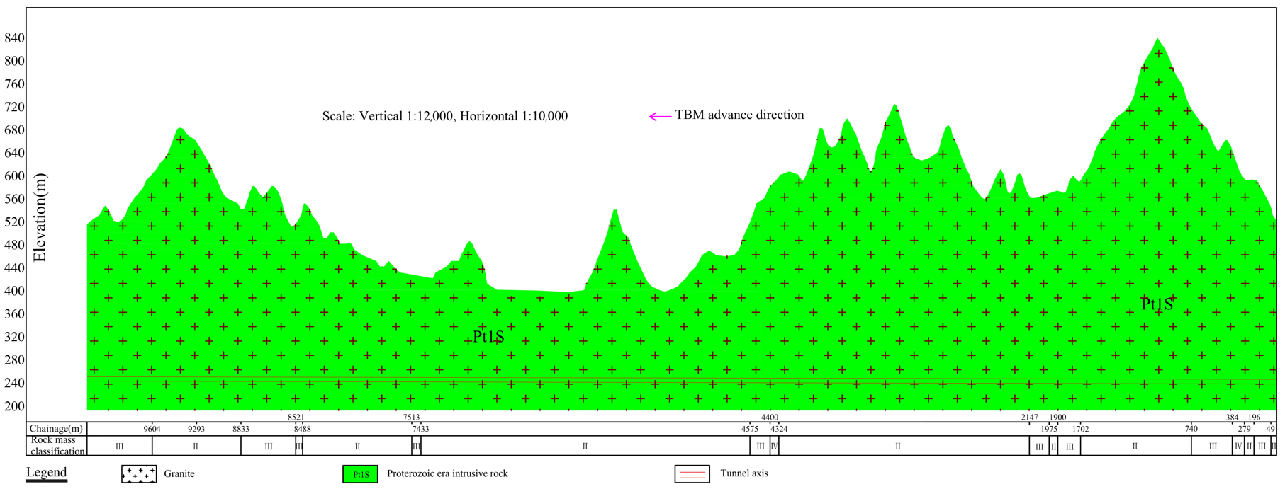
2.1. Project Description

In this paper, the studied project is a water conveyance tunnel with a diameter of 8.50 m and a length of 10 km. The geological profile of the tunnel is shown in Figure 1. The lithology of the surrounding rock is Proterozoic intrusive rock, which is mainly giant porphyritic granite composed of feldspar, quartz, hornblende, and dark minerals. The tunnel wall is mainly dry or locally moist, without an obvious groundwater overflow phenomenon. The joint surfaces are undulating and rough, with some mostly closed and a few slightly open. The surrounding rock is basically stable. The rock mass classification of the studied tunnel was carried out by the hydropower classification (HC) method [2], and the proportions of classes II, III, and IV of the rock mass classification were 81.28%, 16.19%, and 2.53%, respectively.

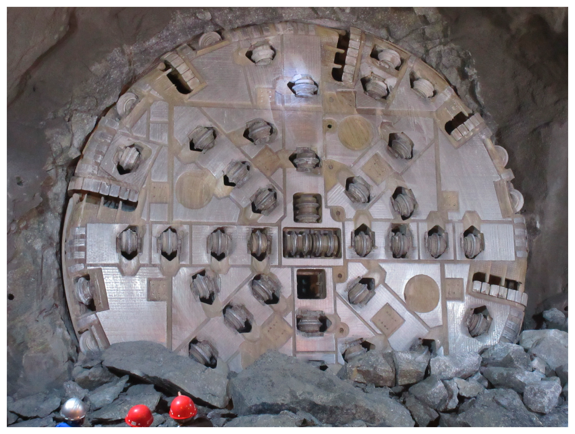
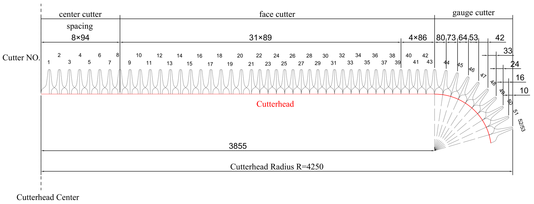
2.2. Machine Specifications and Cutter Arrangement

A gripper TBM was employed for tunnel construction, and the main specifications of the TBM are listed in Table 1. A picture of the front of the cutterhead is shown in Figure 2. A back-installed cutterhead was adopted for safety cutter replacement. The cutters were arranged nonlinearly on the cutterhead. With the increased distance of the disc cutter to the center of the cutterhead, the number of each cutter also increased. A total of 4 double-ring center cutters of 17 inches were installed at the center cutter position (1–8) and arranged in a “cross” shape. The face cutter positions (9–43) and the gauge cutter positions (44–53) were both installed with single-ring disc cutters of 20 inches. The cutter spacing on the cutterhead is shown in Figure 3.
The allowable wear limits of cutter rings are different due to the different sizes and installation positions of disc cutters. As shown in Table 2, the allowable wear limits of cutter rings for gauge cutters are less than that for face cutters, and the former show a step-type decreasing trend with an increase in the cutter number.

3. Cutter Wear in Granite

Cutter inspectors conducted a comprehensive examination of all cutters and recorded their wear extent in detail on the cutter maintenance sheet (see Table 3) during the daily maintenance of the TBM. The cutters were immediately replaced when they reached the allowable wear limit or exhibited abnormal wear. It is worth noting that the statistical data regarding the wear extent and replacement number of cutter rings encompass both normal wear and abnormal wear scenarios in this paper.

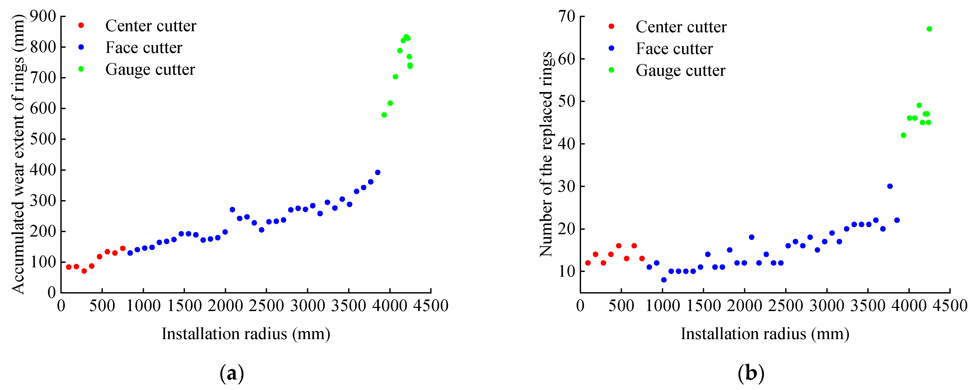
3.1. Analysis of Accumulated Wear Extent and Replacement Number of Cutter Rings with Different Installation Radii

The daily cutter maintenance sheets corresponding to the excavation sections were collected, and the accumulated wear extent and replacement numbers of cutter rings with different installation radii were counted, as shown in Figure 4.
As shown in Figure 4a, with the increases in the installation radius, the accumulated wear extent of the rings shows a linearly increasing trend for both the center cutter and face cutter. This is because the rolling distance and linear speed both increase with the increase in the installation radius, so the cumulative wear of the cutter rings also increases. However, the accumulated wear extent of the rings shows a trend of first increasing and then decreasing for the gauge cutter with the increase in the installation radius. This is because the installation angle increases with the increase in the installation radius, and the contact area between the cutter and the rock on the tunnel face decreases, which results in a lower rate of cutter ring wear [35]. That is to say, the installation radius and installation angle together cause the gauge cutter to present a wear rule of first increasing and then decreasing.
As shown in Figure 4b, for the center cutter, the cutter ring needs to be replaced at the same time as its double ring, and the data points of the accumulated replacement number appear in pairs. The difference between the maximum number and the minimum number of cutter replacements was only four in this research. For the face cutter, the accumulated number of replaced rings shows a linear growth trend with the increase in the installation radius. This is because the rolling distance and linear speed both increased with the increase in the installation radius, but the allowable wear limit of the cutter ring is a fixed value (see Table 2), so the accumulated replacement number of cutter rings increased linearly. For the gauge cutter, the allowable wear limit of the cutter ring shows a step-type decreasing trend with the increase in the installation radius, and the corresponding value of the last cutter position (disc cutters 52 and 53) is the smallest (see Table 2). Therefore, except for the last cutter position, the accumulated replacement numbers of cutter rings show little difference.

3.2. Analysis of Wear Extent for Different Types of Disc Cutters

The ratio of the accumulated wear extent to the cutter number for different types of disc cutters is defined as the accumulated wear extent of the average single cutter position, which were 105.9 mm, 233.7 mm, and 741 mm, respectively, for the center cutter, face cutter, and gauge cutter in this study, as shown in Figure 5. The accumulated wear extent of the average single cutter position of the gauge cutter was about three times that of the face cutter and seven times that of the center cutter. This is because the gauge cutter is subjected to both primary wear and secondary wear. Furthermore, the installation radius of the gauge cutter is larger, and the accumulated wear extent of the gauge cutter is also larger (see Figure 4a), so its wear situation is the most serious.

3.3. Analysis of Cutter Ring Replacements for Different Types of Disc Cutters

The ratio of the total number of replaced cutter rings to the cutter number for different types of disc cutters is defined as the number of replaced cutter rings for the average single cutter position, which were 13.8, 15.3, and 50.1, respectively, for the center cutter, face cutter, and gauge cutter in this study, as shown in Figure 6. The number of replaced cutter rings of the average single cutter position of the gauge cutter was about 3–4 times that for the center cutter and face cutter, which is mainly because, as can be seen in Figure 5, the accumulated wear extent of the average single cutter position of the face cutter was larger than that of the center cutter, but the allowable wear limit of the cutter ring of center cutters is less than that of face cutters (see Table 2), so the number of replaced cutter rings of the average single cutter position of both is comparable. Most new cutters are preferred to be used in the gauge cutter area. Then, the normal-wear cutters are transferred to the face cutter area for sequential use, and the allowable wear limit of the cutter ring for gauge cutters is the lowest (see Table 2). Additionally, the wear rate of gauge cutters is the fastest, so the number of replaced cutter rings for the average single cutter position of the gauge cutter is much larger than that of the center cutter and face cutter.

3.4. Analysis of Average Utilization Rate of Different Types of Disc Cutters

The ratio of the average wear extent at a cutter position to the allowable wear limit of the cutter ring at that cutter position is defined as the average utilization rate at that cutter position, which is calculated in Equation (1):
η i = M i H i δ i
where ηi is the average utilization rate at the i’th cutter position, Mi is the accumulated wear extent of the cutter ring at the i’th cutter position, Hi is the number of replaced cutter rings at the i’th cutter position, and δi is the allowable wear limit of the cutter ring at the i’th cutter position.
The average utilization rates of different types of disc cutters are shown in Figure 7. As shown in Figure 7, the average utilization rate of gauge cutters is the highest (80.97%), followed by face cutters (44.20%), and that of center cutters is the lowest (only 30.82%).
During the daily machine maintenance, the cutter inspectors needed to properly adjust the worn cutters to reduce the difference in the wear extent between adjacent cutters. The center cutters with double rings are closely arranged, so these cutters can only be adjusted between the center cutter positions. In this project, center cutters 1–4 and 5–8 are usually replaced at the same time due to abnormal wear, and the wear extent of the cutter rings is far less than their allowable wear limits, which results in a lowest utilization rate for the center cutter. The cutter rings of the face cutters are always replaced with gauge cutters with normal wear. When the cutter ring is replaced, part of it has been utilized, so the average utilization rate of the face cutter is significantly lower than that of the gauge cutter. The gauge cutter is always replaced with a new cutter ring, and the wear rate of the new cutter ring is faster. In addition, the allowable limit wear of the cutter ring is the lowest, and the cutter ring is fully utilized, so the average utilization rate is the highest.
Based on the above cutter wear rules, we believe that the gauge cutter should be fitted with a larger cutter ring under the conditions of technical feasibility, and the allowable wear limit of a cutter ring should be more refined according to the sizes and installation positions of the disc cutters to reduce mutation.

4. Developing a Cutter Life Prediction Model for Face Cutters

4.1. Selecting a Cutter Life Evaluation Index

The cutter movement track is the vector synthesis of cutterhead advancement and rotation, namely a cylindrical helix. In order to explore the relationship between the wear extent of cutter rings and the cutter rolling distance at different cutter positions, the ratio of the two is defined as the cutter ring wear rate, which is calculated by the following formula [48]:
K i = M i S i
where Ki is the cutter ring wear rate at the i’th cutter position, and Si is the accumulated cutter rolling distance at the i’th cutter position. Si can be approximately calculated by the following formula [48]:
S i L P · 2 π R i
where L is the accumulated TBM advancement distance, P is the average penetration per revolution, and Ri is the installation radius of the cutter at the i’th cutter position.
The wear rate of the cutter ring at different cutter positions is shown in Figure 8. It can be seen that the wear rate of the center cutter ring decreases gradually with the increase in the installation radius. As the installation radius is too small, the center cutter is mainly affected by sliding wear, and the influence degree decreases with the increase in the installation radius, of which cutters 1 and 2 are regarded as anomalous points. The wear rate of the gauge cutter ring is higher than that of the face cutter ring, which is mainly because the gauge cutter is subjected to secondary wear caused by the accumulated rock slags at the bottom of the cutterhead, in addition to the primary wear caused during rock breaking. Face cutters, subjected to primary wear only, are mainly responsible for rock breaking, and the wear rate of the cutter ring is relatively uniform. Therefore, the cutter ring wear rate of the face cutter was selected as the evaluation index to develop the disc cutter life prediction model.

4.2. Sensitivity Analysis

4.2.1. Grey Relational Analysis

There are many parameters that affect cutter wear, and how to establish an excellent cutter life prediction model with fewer parameters is an important issue that needed to be considered in this study. The key to solving this problem is to clarify the sensitivity of various parameter changes to the cutter life evaluation index. Due to the complexity of the relationship between various parameters and the cutter evaluation index, it is not yet fully understood and can be regarded as a grey system (i.e., a system with some clear information and some unclear information). Therefore, the main analysis method in grey system theory (grey relational analysis (GRA)) can serve as an important means to establish a cutter life prediction model. Grey relational analysis can address the shortcomings of traditional analysis methods by quantitatively analyzing indicator values, evolving fuzzy correlation values, and ultimately determining important relationships among various factors, resulting in a correlation degree [49].
An evaluation index system was determined, and the evaluation data were collected according to the evaluation purpose. Suppose n data series form the following matrix:
( X 0 , X 1 , , X i , , X m ) T = x 0 ( 1 ) x 0 ( 2 ) x 0 ( n ) x 1 ( 1 ) x 1 ( 2 ) x 1 ( n ) ···· ···· ···· ···· ···· ···· ···· ···· ···· ····· x i ( 1 ) x i ( 2 ) x i ( n ) ···· ···· ···· ···· ···· ···· ···· ···· ···· ····· x m ( 1 ) x m ( 2 ) x m ( n )
where m is the number of indicators, Xi = (xi(1), xi(2),…, xi(n)). X0 is defined as the reference series with the comparison series X1Xm.
The main processes of applying grey sensitivity analysis are as follows:
① Determining reference series X0 and comparison series Xi (i = 1, 2, …, m).
② Non-dimensional data: As the physical meanings, units, and orders of magnitude of each series are different, it was impossible to compare them directly, so the initial value method was employed to dimensionless processing in this paper. Xi (i = 0, 1, 2, ···, m) is defined as the non-dimensional series, and the initial value method was calculated as follows:
X i = X i / x i ( 1 ) = ( x i ( 1 ) , x i ( 2 ) , , x i ( n ) ) , ( i = 0 , 1 , 2 , , m )
③ Calculating the absolute value of difference value |Δi(k)| between the reference series and the comparison series. The calculation formula is as follows:
Δ i ( k ) = x 0 ( k ) x i ( k ) ( i = 1 , 2 , , m ; k = 1 , 2 , , n )
④ Determining the maximum value M and the minimum value m of |Δi(k)|.
⑤ Calculating the sensitivity coefficient, ζ ( x 0 ( k ) , x i ( k ) ) :
ζ ( x 0 ( k ) , x i ( k ) ) = m + ρ M Δ i ( k ) + ρ M ( ρ ( 0 , 1 ) ; i = 1 , 2 , , m ; k = 1 , 2 , , n )
where ρ is the discrimination coefficient, and the smaller ρ is, the greater the differences are among the sensitivity coefficients, and the stronger the discrimination ability is. ρ is usually taken as 0.5.
⑥ Calculating the sensitivity, ζ ( x 0 , x i ) :
ζ ( x 0 , x i ) = 1 n k = 1 n ζ ( x 0 ( k ) , x i ( k ) ) ( i = 1 , 2 , , m )

4.2.2. Sensitivity Analysis of Cutter Ring Wear Rate to Intact Rock Parameters and TBM Tunneling Parameters

When the daily advancement was lower, the cutter inspectors did not measure the wear extent of each cutter ring, so the daily cutter wear data were not obtained. The cutter ring wear rate of face cutters was calculated every 3–5 days with about 100 m of advancement. The corresponding rock type within each excavation section of 100 m needs to be consistent. When the rock types significantly change, the excavation section is automatically reclassified. Meanwhile, considering that TBM needs to be debugged in the early stages of TBM tunneling, the field data of the previous two months were excluded for the learning effect. Figure 9 shows the variations in the cutter ring wear rate of the face cutter throughout the studied project.
Two main factors affect cutter wear, namely geological parameters and TBM tunneling parameters. Considering the distribution characteristics of the cutter ring wear rate of the face cutter, field rock corings were conducted at 12 different positions, and then laboratory tests were conducted for measuring the commonly used intact rock parameters characterizing rock abrasiveness (including UCS, Q, EQC, CAI, and RAI). In addition, during the TBM tunneling process, the TBM driver needed to fill in daily on-site tunneling reports to record the TBM tunneling parameters, including the penetration rate (PR), cutterhead thrust (F), cutterhead torque (T), cutterhead rotational speed (RPM), and penetration per revolution (PRev). The influence parameters and cutter ring wear rate of the face cutter are shown in Table 4. It should be emphasized that the values in Table 4 are average values.
The sensitivity of the cutter ring wear rate of the face cutter to the intact rock parameters and TBM tunneling parameters was studied. As the sample parameters were non-dimensional, the calculated sensitivity values have no quantitative meaning and were only used as a reference for qualitative analysis of the primary and secondary relationships among the various sensitivity factors within the same group. The results are shown in Figure 10.
As shown in Figure 10a, the order of the sensitivity of the cutter ring wear rate of the face cutter to the five intact rock parameters from largest to smallest was UCS, CAI, EQC, Q, and RAI. This suggests that a single Q value cannot reliably predict cutter wear. Logically, the greater the proportion of hard minerals (specifically quartz) in a rock, meaning that the rock is harder, the greater its abrasiveness. Additionally, the structure of the rock itself influences the cutter wear; thus, the sensitivity of the EQC rises when considering the rock’s mineral composition and hardness. Furthermore, it was discovered that the sensitivity of RAI, derived from multiplying the two highly sensitive UCS and EQC, decreases. This is associated with the principles of grey relational analysis. In the calculations, both the reference and comparison sequences were normalized. If the trends in these sequences are aligned, indicating a high degree of synchronous change and a correspondingly high level of correlation between the two, then the resulting multiplication amplifies any lack of correlation between the new sequence and the reference sequence, thereby reducing the sensitivity of the RAI.
As shown in Figure 10b, the order of the sensitivity of the cutter ring wear rate of the face cutter to the five TBM tunneling parameters from largest to smallest was F, RPM, PR, T, and PRev. PR and PRev mainly reflect the excavation efficiency of TBM, and both of them are affected by many factors on-site, but they cannot directly present the working conditions of the disc cutters on the cutterhead. During TBM excavation, the TBM driver usually controls the T within a reasonable range to protect the cutter. Therefore, the sensitivity of the cutter ring wear rate of the face cutter to PR, PRev, and T is relatively low. When the F and RPM increase, the depth of the rock breaking and the rolling distance per unit of time of the cutter will both increase, exacerbating the wear of the cutter ring. Therefore, the sensitivity of the cutter ring wear rate to F and RPM is relatively high.

4.3. Development of a New Cutter Life Prediction Model

The above sensitivity analysis can only qualitatively describe the sensitivity order of the two types of influence parameters, but it is incapable of providing a specific relationship. In order to ensure the accuracy of the developed model, three intact rock parameters (including UCS, CAI, and EQC) and two TBM tunneling parameters (including F and RPM) with the highest sensitivity were selected as independent variables, and the cutter ring wear rate of the face cutter K was selected as a dependent variable. Finally, the stepwise forward regression analysis built into Statistical Product Service Solutions (SPSS) software 23 was used to evaluate the effect of each independent variable on K [50].
The final results are shown in Table 5. The CAI and EQC were excluded due to multicollinearity problems with the other independent variables, and the final model includes three independent variables, namely F, UCS, and RPM. As shown in Table 5, the R square value was 0.964, which means that the UCS, F, and RPM can explain 96.4% of the variation in K. Moreover, the model passed the F-test, indicating its effectiveness. In addition, a test was conducted on the multicollinearity of the model, and it was found that all VIF values in the model were less than 5, indicating that there was no collinearity issue. The D-W value was around 2, indicating that the model did not have autocorrelation, and there were no correlations among the sample data.
Multiple regression analysis was used to obtain the optimal linear combination of the three independent variables at a 95% confidence level, and the best-fitting model with the maximum determination coefficient (R2 = 0.964) is as follows:
K = 2.304 × 10 9 F + 6.097 × 10 8 U C S 4.758 × 10 6 R P M 6.620 × 10 6
Figure 11 shows a comparison of the measured and predicted values of K. It can be seen that the predicted values calculated according to Equation (9) are close to the measured values, which verifies the accuracy of the developed model.
It should be pointed out that only projects with similar geological conditions (granite formations with good rock integrity and a UCS range of 40–100 MPa) and TBM specifications can adopt the empirical relationship proposed in this paper. Considering that the proposed empirical equation was developed based on field data from a single tunnel and the research object was only a face cutter, it is necessary to collect more field data in the future to revise and expand the model developed in this paper, as well as to obtain a general cutter life prediction model applicable to different types of disc cutters.

5. Conclusions

In this paper, through statistical analysis of field data on cutter wear in a TBM tunnel, the cutter wear in granite was explored, and grey relational analysis was used to explore the sensitivity between the cutter ring wear rate of the face cutter and two types of cutter wear influence parameters. Finally, a new cutter life prediction model was developed by selecting reasonable parameters, and the following conclusions are drawn:
(1)
With increases in the installation radius, the accumulated wear extent showed a linearly increasing trend for both the center and the face cutter, while it increased first and then decreased for the gauge cutter, and the accumulated replacement number showed a linear growth trend for the face cutter.
(2)
The accumulated wear extent of the average single cutter position of the gauge cutter was about three times that of the face cutter and seven times that of the center cutter.
(3)
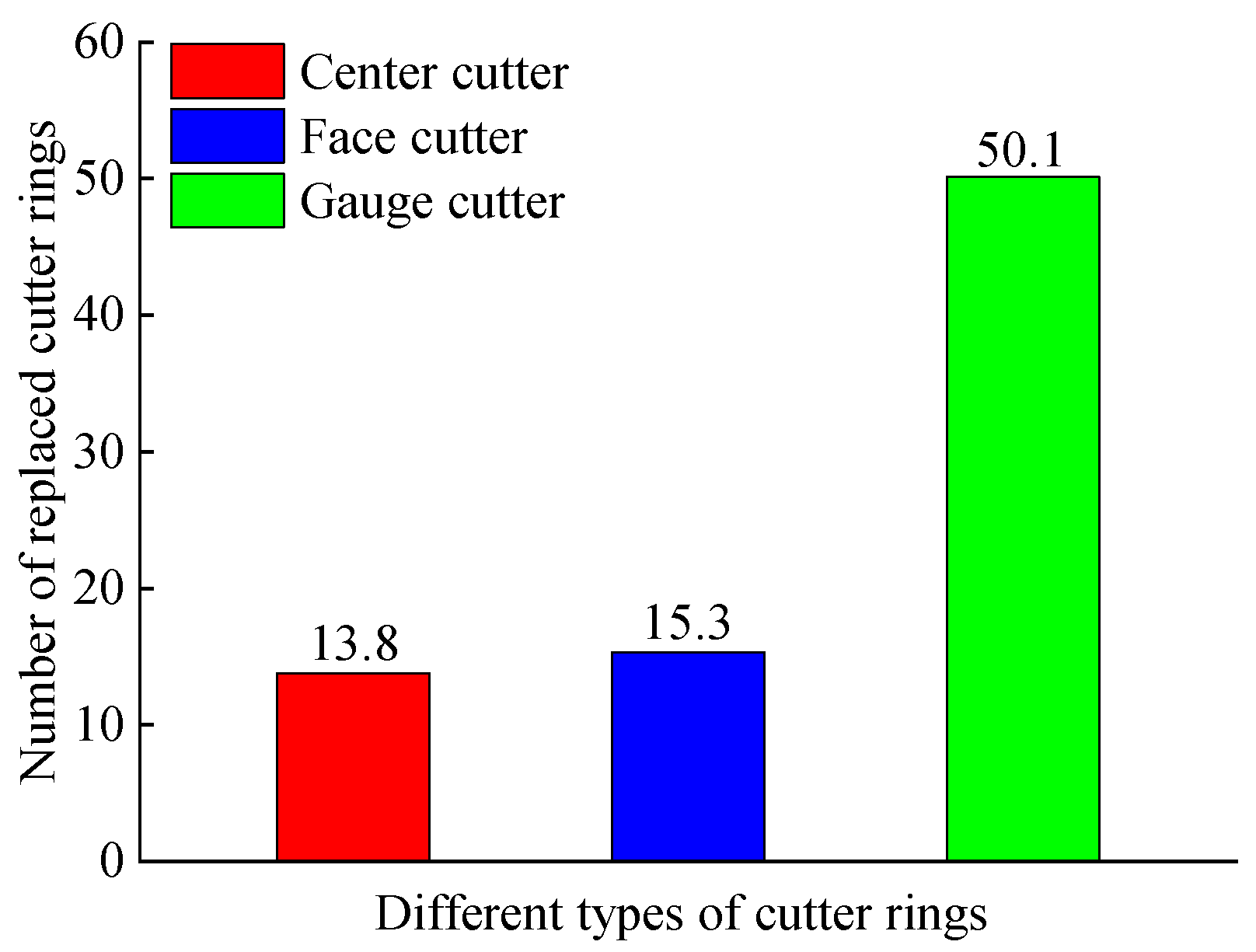
The numbers of replaced cutter rings for the average single cutter position of the center cutter and face cutter were comparable, and the number of replaced cutter rings for the average single cutter position of the gauge cutter was about 3–4 times that of the center cutter and face cutter.
(4)
The average utilization rate of the gauge cutter was the highest (80.97%), followed by the face cutter (44.20%), and that of the center cutter was the lowest (only 30.82%).
(5)
The sensitivity of the cutter ring wear rate of the face cutter to the intact rock parameters was in the following order: UCS, CAI, EQC, Q, and RAI, and that to the TBM tunneling parameters was in the following order: F, RPM, PR, T, and PRev. A prediction model (R2 = 0.964) for the cutter ring wear rate of the face cutter based on F, UCS, and RPM was established through multiple regression analysis.

Author Contributions

Conceptualization, J.L.; methodology, T.H.; software, T.H.; investigation, Y.P., X.P. and J.L.; data curation, T.H.; writing—original draft, T.H.; writing—review and editing, Y.P., X.P. and J.L. All authors have read and agreed to the published version of the manuscript.

Funding

This research was funded by the National Natural Science Foundation of China, grant № 41907242 and 42177140.

Data Availability Statement

The data presented in this study are available on request from the corresponding author due to that the cutter wear data used in the study are confidential.

Conflicts of Interest

Author Xingxin Peng was employed by the company China Railway 11th Bureau Group Fourth Engineering Co., Ltd. The remaining authors declare that the research was conducted in the absence of any commercial or financial relationships that could be construed as a potential conflict of interest.

References

  1. Liu, Q.S.; Huang, X.; Gong, Q.M.; Du, L.J.; Pan, Y.C.; Liu, J.P. Application and development of hard rock TBM and its prospect in China. Tunn. Undergr. Space Technol. 2016, 57, 33–46. [Google Scholar] [CrossRef]
  2. Liu, Q.S.; Liu, J.P.; Pan, Y.C.; Kong, X.X.; Hong, K.R. A case study of TBM performance prediction using a Chinese rock mass classification system—Hydropower Classification (HC) method. Tunn. Undergr. Space Technol. 2017, 65, 140–154. [Google Scholar] [CrossRef]
  3. Liu, Q.S.; Liu, J.P.; Pan, Y.C.; Zhang, X.P.; Peng, X.X.; Gong, Q.M.; Du, L.J. A wear rule and cutter life prediction model of a 20-in. TBM cutter for granite: A case study of a water conveyance tunnel in China. Rock Mech. Rock Eng. 2017, 50, 1303–1320. [Google Scholar] [CrossRef]
  4. Liu, B.; Chen, L.; Li, S.C.; Song, J.; Xu, X.J.; Li, M.; Nie, L.C. Three-Dimensional Seismic Ahead-Prospecting Method and Application in TBM Tunneling. J. Geotech. Geoenviron. Eng. 2017, 143, 04017090. [Google Scholar] [CrossRef]
  5. Barzegari, G.; Khodayari, J.; Rostami, J. Evaluation of TBM cutter wear in naghadeh water conveyance tunnel and developing a new prediction model. Rock Mech. Rock Eng. 2021, 54, 6281–6297. [Google Scholar] [CrossRef]
  6. Jiang, Y.L.; Zeng, J.J.; Xu, C.J.; Xiong, F.Y.; Pan, Y.C.; Chen, X.S.; Lei, Z.X. Experimental study on TBM cutter penetration damage process of highly abrasive hard rock pre-cut by high-pressure water jet. Bull. Eng. Geol. Environ. 2022, 81, 511. [Google Scholar] [CrossRef]
  7. Zhang, Y.; Chen, J.Q.; Han, S.; Li, B. Big Data-Based Performance Analysis of Tunnel Boring Machine Tunneling Using Deep Learning. Buildings 2022, 12, 1567. [Google Scholar] [CrossRef]
  8. Wen, S.; Zhang, C.S. Experimental and simulation study on rock-breaking efficiency of disc cutters on composite rocks. Int. J. Rock Mech. Min. Sci. 2022, 153, 105089. [Google Scholar] [CrossRef]
  9. Liu, B.L.; Yang, H.Q.; Wang, G.L.; Gao, H.C.; Ren, J.X. Prediction of disc cutter wear considering the argillization effect. Int. J. Geomech. 2023, 23, 04023062. [Google Scholar] [CrossRef]
  10. Yu, H.G.; Qin, C.J.; Tao, J.F.; Liu, C.L.; Liu, Q.S. A multi-channel decoupled deep neural network for tunnel boring machine torque and thrust prediction. Tunn. Undergr. Space Technol. 2023, 133, 104949. [Google Scholar] [CrossRef]
  11. Liu, J.P.; He, T.K.; Zhou, Z.J.; Peng, X.X.; Pan, Y.C. Analysis and Enlightenment on the Relationships between Two Kinds of Cutter Life Evaluation Indexes and Installation Radius: A Case Study. Buildings 2024, 14, 1523. [Google Scholar] [CrossRef]
  12. Yang, T.T. Investigation on Disaster Mechanism of Diversion Tunnel Induced by Gripper TBM in Hydrokarst Erosion Stratum and Engineering Measures. Buildings 2024, 14, 625. [Google Scholar] [CrossRef]
  13. Ding, Y.; Hang, D.; Wei, Y.J.; Zhang, X.L.; Ma, S.Y.; Liu, Z.X.; Zhou, S.X.; Han, Z. Settlement prediction of existing metro induced by new metro construction with machine learning based on SHM data: A comparative study. J. Civ. Struct. Health Monit. 2023, 13, 1447–1457. [Google Scholar] [CrossRef]
  14. Ding, Y.; Wei, Y.J.; Xi, P.S.; Ang, P.P.; Han, Z. A long-term tunnel settlement prediction model based on BO-GPBE with SHM data. Smart Struct. Syst. 2024, 33, 17–26. [Google Scholar] [CrossRef]
  15. Liu, B.L.; Yang, H.Q.; Karekal, S. Reliability analysis of TBM disc cutters under different conditions. Undergr. Space 2021, 6, 142–152. [Google Scholar] [CrossRef]
  16. Hu, M.M.; Zhang, B.; Li, B.; Liu, B.; Cao, W.Z.; Xu, B. TBM-cutter rock-breaking effect and mechanism considering different cutting sequences. Bull. Eng. Geol. Environ. 2022, 81, 102. [Google Scholar] [CrossRef]
  17. Huang, X.; Liu, Q.S.; Shi, K.; Pan, Y.C.; Liu, J.P. Application and prospect of hard rock TBM for deep roadway construction in coal mines. Tunn. Undergr. Space Technol. 2018, 73, 105–126. [Google Scholar] [CrossRef]
  18. Huang, X.; Zhang, Q.T.; Liu, Q.S.; Liu, X.W.; Liu, B.; Wang, J.J.; Yin, X. A real-time prediction method for tunnel boring machine cutter-head torque using bidirectional long short-term memory networks optimized by multi-algorithm. J. Rock Mech. Geotech. Eng. 2022, 14, 798–812. [Google Scholar] [CrossRef]
  19. Elbaz, K.; Shen, S.L.; Zhou, A.N.; Yin, Z.Y.; Lyu, H.M. Prediction of Disc Cutter Life During Shield Tunneling with AI via the Incorporation of a Genetic Algorithm into a GMDH-Type Neural Network. Engineering 2021, 7, 238–251. [Google Scholar] [CrossRef]
  20. Yang, H.Q.; Liu, B.L.; Wang, Y.Q.; Li, C.C. Prediction model for normal and flat wear of disc cutters during TBM tunneling process. Int. J. Geomech. 2021, 21, 06021002. [Google Scholar] [CrossRef]
  21. Gao, B.Y.; Wang, R.R.; Lin, C.J.; Guo, X.; Liu, B.; Zhang, W.A. TBM penetration rate prediction based on the long short-term memory neural network. Undergr. Space 2021, 6, 718–731. [Google Scholar] [CrossRef]
  22. Wu, Z.J.; Wei, R.L.; Chu, Z.F.; Liu, Q.S. Real-time rock mass condition prediction with TBM tunneling big data using a novel rock-machine mutual feedback perception method. J. Rock Mech. Geotech. Eng. 2021, 13, 1311–1325. [Google Scholar] [CrossRef]
  23. Hou, S.K.; Liu, Y.R.; Yang, Q. Real-time prediction of rock mass classification based on TBM operation big data and stackingtechnique of ensemble learning. J. Rock Mech. Geotech. Eng. 2022, 14, 123–143. [Google Scholar] [CrossRef]
  24. Rong, X.N.; Lu, H.; Wang, M.Y.; Wen, Z.; Rong, X. Cutter wear evaluation from operational parameters in EPB tunneling of Chengdu Metro. Tunn. Undergr. Space Technol. 2019, 93, 103043. [Google Scholar] [CrossRef]
  25. Ge, Y.H.; Liu, Y.B.; Lin, P.; Xu, Z.H. Effects of rock properties on the wear of TBM disc cutter: A case study of the Yellow River diversion project, China. Int. J. Geomech. 2022, 22, 04022011. [Google Scholar] [CrossRef]
  26. Yang, H.Q.; Wang, H.; Zhou, X.P. Analysis on the Rock–Cutter Interaction Mechanism During the TBM Tunneling Process. Rock Mech. Rock Eng. 2016, 49, 1073–1090. [Google Scholar] [CrossRef]
  27. Zhang, X.P.; Ji, P.Q.; Liu, Q.S.; Liu, Q.; Zhang, Q.; Peng, Z.H. Physical and numerical studies of rock fragmentation subject to wedge cutter indentation in the mixed ground. Tunn. Undergr. Space Technol. 2018, 71, 354–365. [Google Scholar] [CrossRef]
  28. Wu, Q.W.; Zhou, X.L.; Pan, X.M. Cutting tool wear monitoring in milling processes by integrating deep residual convolution network and gated recurrent unit with an attention mechanism. Proc. Inst. Mech. Eng. Part B-J. Eng. Manuf. 2023, 237, 1171–1181. [Google Scholar] [CrossRef]
  29. Ren, D.J.; Shen, S.L.; Arulrajah, A.; Cheng, W.C. Prediction model of TBM disc cutter wear during tunnelling in heterogeneous ground. Rock Mech. Rock Eng. 2018, 51, 3599–3611. [Google Scholar] [CrossRef]
  30. Karami, M.; Zare, S.; Rostami, J. Introducing an empirical model for prediction of disc cutter life for TBM application in jointed rocks: Case study, Kerman water conveyance tunnel. Bull. Eng. Geol. Environ. 2021, 80, 3853–3870. [Google Scholar] [CrossRef]
  31. Farrokh, E.; Kim, D.Y. A discussion on hard rock TBM cutter wear and cutterhead intervention interval length evaluation. Tunn. Undergr. Space Technol. 2018, 81, 336–357. [Google Scholar] [CrossRef]
  32. Hassanpour, J.; Rostami, J.; Zhao, J.; Azali, S.T. TBM performance and disc cutter wear prediction based on ten years experience of TBM tunnelling in Iran. Geomech. Tunn. 2015, 8, 239–247. [Google Scholar] [CrossRef]
  33. Geng, Q.; Bruland, A.; Macias, F.J. Analysis on the Relationship between Layout and Consumption of Face Cutters on Hard Rock Tunnel Boring Machines (TBMs). Rock Mech. Rock Eng. 2017, 51, 279–297. [Google Scholar] [CrossRef]
  34. Yang, J.H.; Zhang, X.P.; Ji, P.Q.; Liu, Q.S.; Lu, X.J.; Wei, J.P.; Qi, S.H.; Fang, H.G.; Fang, J.N.; Geng, Y.J. Analysis of disc cutter damage and consumption of TBM1 section on water conveyance tunnel at Lanzhou water source construction engineering. Tunn. Undergr. Space Technol. 2019, 85, 67–75. [Google Scholar] [CrossRef]
  35. Zhou, Z.L.; Tan, Z.S.; Li, Z.L.; Ma, D.; Zhang, L.L. TBM cutter wear under high-strength surrounding rock conditions: A case study from the second phase of the Northern Xinjiang water supply project. Rock Mech. Rock Eng. 2021, 54, 5023–5039. [Google Scholar] [CrossRef]
  36. Shi, M.L.; Hu, W.F.; Li, M.X.; Zhang, J.; Song, X.G.; Sun, W. Ensemble regression based on polynomial regression-based decision tree and its application in the in-situ data of tunnel boring machine. Mech. Syst. Signal Proc. 2023, 188, 110022. [Google Scholar] [CrossRef]
  37. Wang, L.H.; Kang, Y.H.; Cai, Z.X.; Zhan, Q.; Zhao, Y.; Zhao, H.F.; Su, P.C. The energy method to predict disc cutter wear extent for hard rock TBMs. Tunn. Undergr. Space Technol. 2012, 28, 183–191. [Google Scholar] [CrossRef]
  38. Wang, L.H.; Kang, Y.L.; Zhao, X.J.; Zhang, Q. Disc cutter wear prediction for a hard rock TBM cutterhead based on energy analysis. Tunn. Undergr. Space Technol. 2015, 50, 324–333. [Google Scholar] [CrossRef]
  39. Wang, L.H.; Li, H.P.; Zhao, X.J.; Zhang, Q. Development of a prediction model for the wear evolution of disc cutters on rock TBM cutterhead. Tunn. Undergr. Space Technol. 2017, 67, 147–157. [Google Scholar] [CrossRef]
  40. Hassanpour, J. Development of an empirical model to estimate disc cutter wear for sedimentary and low to medium grade metamorphic rocks. Tunn. Undergr. Space Technol. 2018, 75, 90–99. [Google Scholar] [CrossRef]
  41. Sun, Z.C.; Zhao, H.L.; Hong, K.R.; Chen, K.; Zhou, J.J.; Li, F.Y.; Zhang, B.; Song, F.L.; Yang, Y.D.; He, R.Y. A practical TBM cutter wear prediction model for disc cutter life and rock wear ability. Tunn. Undergr. Space Technol. 2019, 85, 92–99. [Google Scholar] [CrossRef]
  42. Su, W.L.; Li, X.G.; Jin, D.L.; Yang, Y.; Qin, R.C.; Wang, X.Y. Analysis and prediction of TBM disc cutter wear when tunneling in hard rock strata: A case study of a metro tunnel excavation in Shenzhen, China. Wear 2020, 446–447, 203190. [Google Scholar] [CrossRef]
  43. Lan, H.; Xia, Y.M.; Miao, B.; Fu, J.; Ji, Z.Y. Prediction model of wear rate of inner disc cutter of engineering in Yinsong, Jilin. Tunn. Undergr. Space Technol. 2020, 99, 103338. [Google Scholar] [CrossRef]
  44. Karami, M.; Zare, S.; Rostami, J. Tracking of disc cutter wear in TBM tunneling: A case study of Kerman water conveyance tunnel. Bull. Eng. Geol. Environ. 2021, 80, 201–219. [Google Scholar] [CrossRef]
  45. Yu, H.G.; Tao, J.F.; Huang, S.; Qin, C.J.; Xiao, D.Y.; Liu, C.L. A field parameters-based method for real-time wear estimation of disc cutter on TBM cutterhead. Autom. Constr. 2021, 124, 103603. [Google Scholar] [CrossRef]
  46. She, L.; Zhang, S.R.; Wang, C.; Li, Y.L.; Du, M. A new method for wear estimation of TBM disc cutter based on energy analysis. Tunn. Undergr. Space Technol. 2023, 131, 104840. [Google Scholar] [CrossRef]
  47. Zhang, F.Q.; Xu, F.L.; Zhou, X.L.; Ding, K.; Shao, S.J.; Du, C.; Leng, J.W. Data-driven and knowledge-guided prediction model of milling tool life grade. Int. J. Comput. Integr. Manuf. 2023, 37, 669–684. [Google Scholar] [CrossRef]
  48. Yang, Y.D.; Hong, K.R.; Sun, Z.C.; Chen, K.; Li, F.Y.; Zhou, J.J.; Zhang, B. The derivation and validation of TBM disc cutter wear prediction model. Geotech. Geol. Eng. 2018, 36, 3391–3398. [Google Scholar] [CrossRef]
  49. Deng, J.L. Gray Theory Foundation, 1st ed.; Huazhong University of Science and Technology Press: Wuhan, China, 2002. [Google Scholar]
  50. Zhang, W.T.; Dong, W. Advanced Course of SPSS Statistical Analysis, 3rd ed.; Higher Education Press: Beijing, China, 2018. [Google Scholar]
Figure 1. Geological profile of the tunnel.
Buildings 14 02453 g001
Figure 2. TBM cutterhead.
Buildings 14 02453 g002
Figure 3. Layout of cutter spacing (unit: mm).
Buildings 14 02453 g003
Figure 4. Cutter wear with different installation radii: (a) accumulated wear extent of rings and (b) accumulated number of replaced rings.
Buildings 14 02453 g004
Figure 5. Accumulated wear extent of average single cutter positions.
Buildings 14 02453 g005
Figure 6. Number of replaced cutter rings for the average single cutter position.
Buildings 14 02453 g006
Figure 7. Average utilization rate of different types of disc cutters.
Buildings 14 02453 g007
Figure 8. Cutter ring wear rates at different cutter positions.
Buildings 14 02453 g008
Figure 9. Variations in the cutter ring wear rate of the face cutter throughout the studied project.
Buildings 14 02453 g009
Figure 10. Diagram of sensitivity analysis: (a) intact rock parameters and (b) TBM tunneling parameters.
Buildings 14 02453 g010
Figure 11. Measured and predicted values of K.
Buildings 14 02453 g011
Table 1. Main specifications of the TBM.
Technical ParameterDesign Value
TBM modelRobbins MB280
(Robbins Co., Solon, OH, USA)
TBM diameter (m)8.5
Cutterhead power (kW)3300
Cutterhead nominal torque (kN·m)6713
Cutterhead nominal thrust (kN)16,509.5
Maximum allowable thrust (kN)20,491 at 345 bar
Rotational speed (rpm)0–6.9
Thrust cylinder stroke (mm)1829
Conveyor capacity (t/h)2196
Table 2. Allowable wear limits of cutter rings with different cutter numbers.
Cutter Number1–89–4344–4647–5152–53
Allowable wear limit (mm)2535251912
Table 3. TBM cutter maintenance sheet.
Date:Mileage:Maintenance Start Time:Maintenance End Time:Recorder:
Cutter Position №Disc Cutter NumberReasonWear Extent (mm)
DetachmentInstallationDetachmentInstallation
1
3
2
4
5
7
6
8
9
10
52
53
Table 4. Influence parameters and cutter ring wear rates of face cutter.
Chainage
(m)
Intact Rock ParametersTBM Tunneling ParametersK (mm/m)
UCS (MPa)Q (%)EQC (%)CAIRAIPR (m/h)F (kN)T (kN·m)RPM (r/min)PRev (mm/r)
125819527444.2432.5017,91526005.927.011.23374 × 10−5
229239019434.0382.4718,13824705.877.001.31062 × 10−5
342726519393.8251.8718,11519696.195.019.31849 × 10−6
444915512274.0153.3118,43725255.737.701.19706 × 10−5
552836517374.3252.9418,76828396.367.631.01884 × 10−5
658288524394.3332.2319,21923486.156.041.34693 × 10−5
767403512272.9103.1116,91628216.208.355.69578 × 10−6
872988014354.0292.6918,80727046.206.741.27790 × 10−5
975886530494.5322.8117,98855176.147.501.01972 × 10−5
1085304024281.8122.9316,64725766.087.964.27676 × 10−6
118592459222.6102.6515,77425456.039.104.23748 × 10−6
1210,1917513324.0242.6817,88428106.087.288.93241 × 10−6
Table 5. Stepwise forward regression analysis results.
Unstandardized CoefficientsStandardized CoefficientstpCollinearity Diagnosis
BSEBetaVIFTolerance
Constant−6.620 × 10−60.000 −0.7830.456
UCS (MPa)6.097 × 10−80.0000.3573.7030.0062.0570.486
F (kN)2.304 × 10−90.0000.6807.1050.0002.0320.492
RPM (r/min)−4.758 × 10−60.000−0.242−3.3810.0101.1360.880
R squared0.964
Adjusted R squared0.950
F-testF (3,8) = 71.041, p = 0.000
D-W2.047
Disclaimer/Publisher’s Note: The statements, opinions and data contained in all publications are solely those of the individual author(s) and contributor(s) and not of MDPI and/or the editor(s). MDPI and/or the editor(s) disclaim responsibility for any injury to people or property resulting from any ideas, methods, instructions or products referred to in the content.

