
Optimization of Lower Suspension Point Position in Attached Cantilever Scaffold
 , ,
, ,
Abstract
:1. Introduction
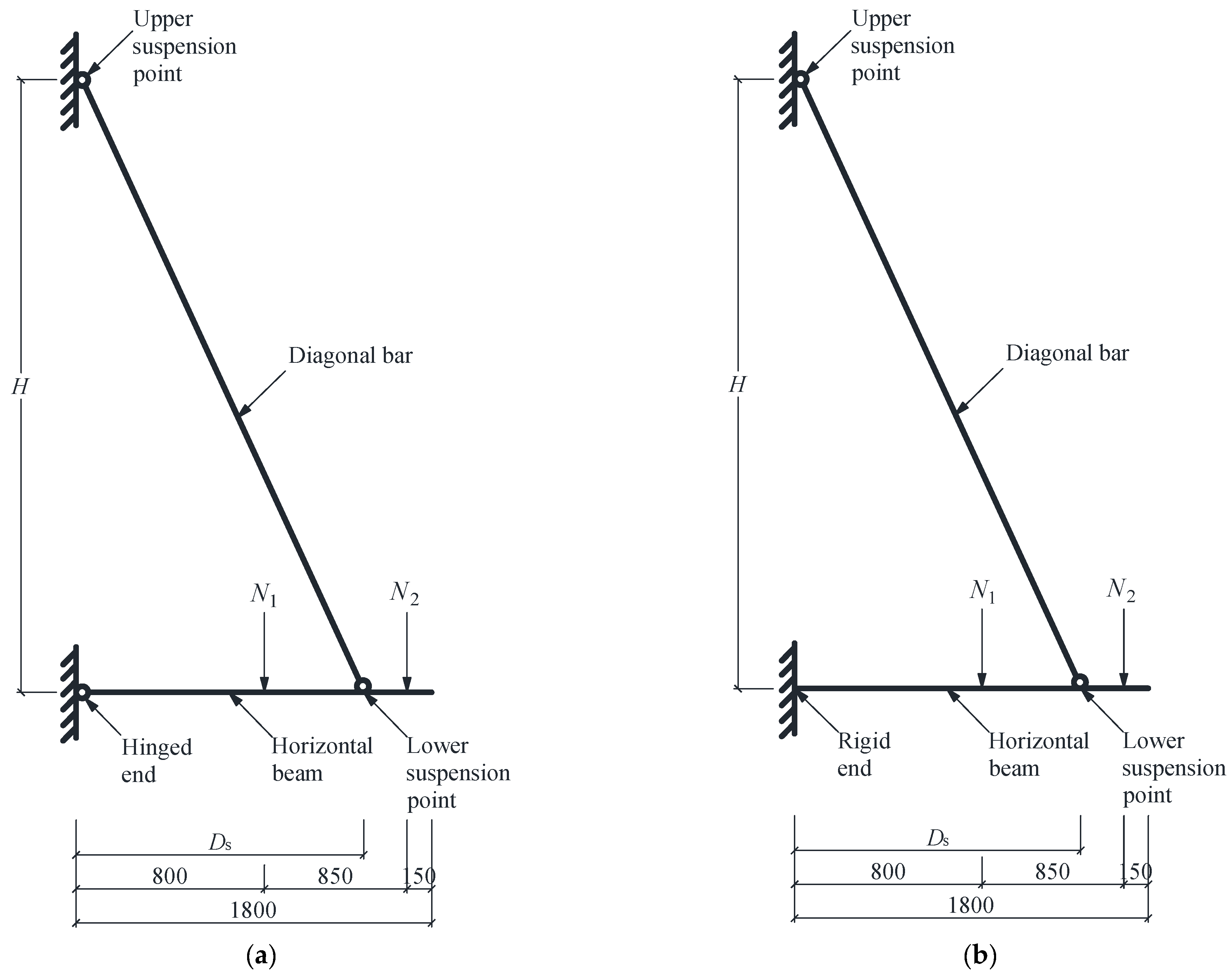
2. Analytical Model
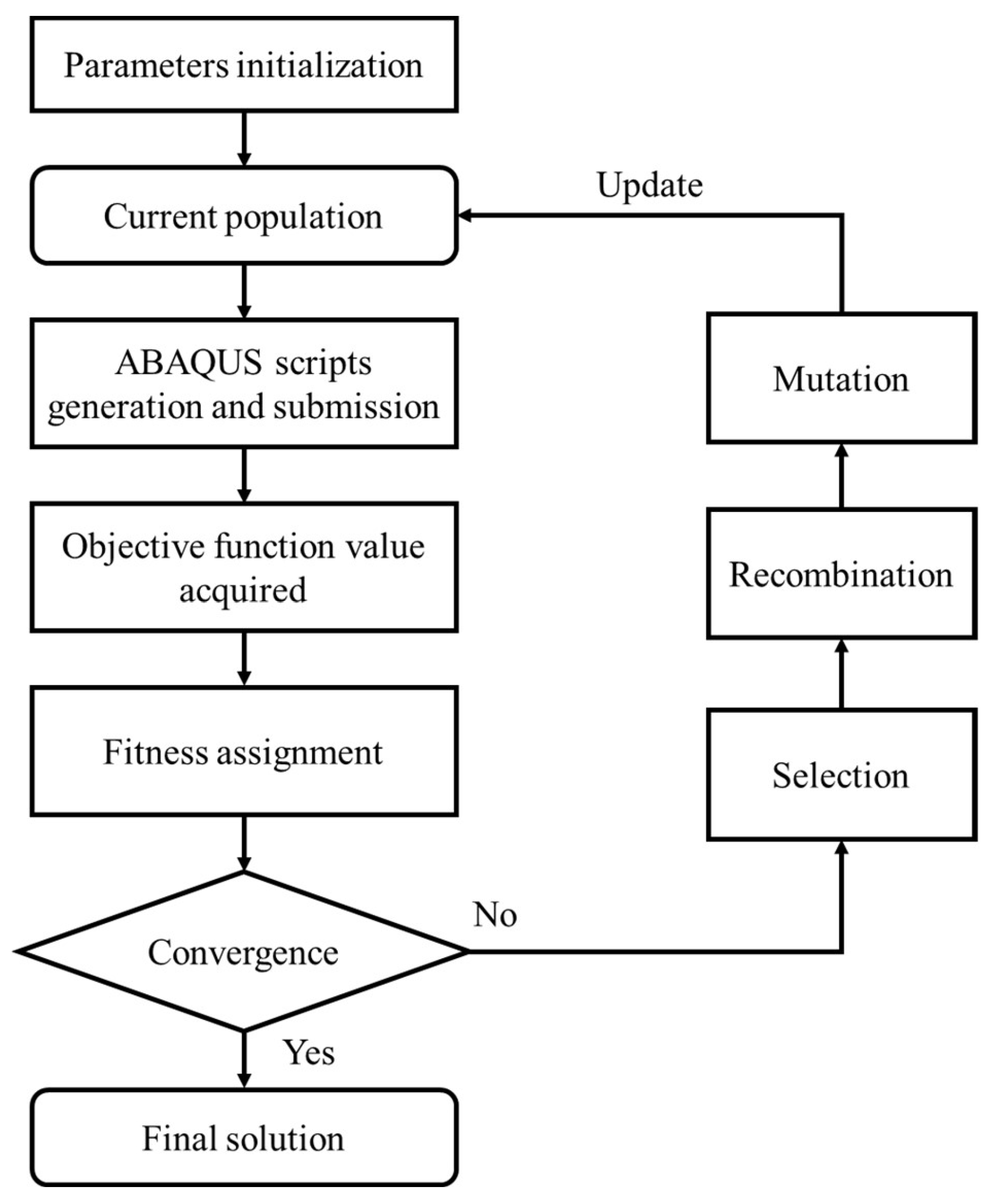
3. Optimization Method
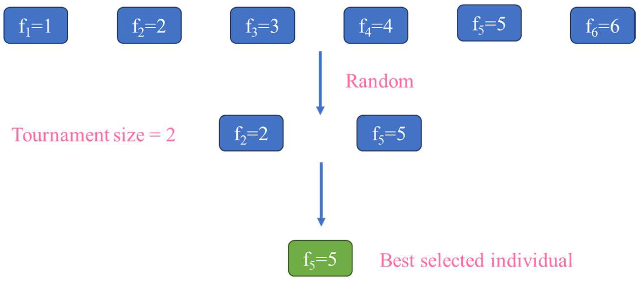
- Selection: The selection operation involves selecting individuals from the current population based on fitness criteria. Therefore, the individuals more suited to the environment are chosen. The number of offspring an individual produces is determined by its fitness. Individuals with higher fitness reproduce more, while those with lower fitness reproduce less or are directly eliminated. This iterative process results in a population with higher-adaptability individuals. The tournament selection algorithm is utilized to select individuals with higher fitness to create stronger offspring [38]. Figure 3 presents the process of the tournament selection. During each selection, two individuals are randomly chosen from the present population as contestants. The individual with the higher fitness value is the winner, and its replicator is selected into a population for the next genetic operation. The winner also returns to the original population to participate in the selection again. This step is repeated until a sufficient number (set as 20 in this study) of individuals are selected into the new population for the next genetic operation.
- Recombination: The recombination operation involves randomly pairing individuals selected for reproduction and determination. The set crossover probability determines whether a crossover operation should be performed on each pair. If a crossover is to be performed, corresponding positions in the genotype of the pair are randomly chosen and swapped. Various methods exist for crossover operations. In this study, the two-point crossover strategy is utilized. Combined with the BG encoding approach, the two-point crossover strategy could generate more types of children within the searching space and could facilitate convergence.
- Mutation: Based on natural gene mutation, a gene value is changed at a certain probability for each selected individual. When all individuals have identical genes but are not globally optimal, crossover will not change the genotype of the individuals. In the case of falling into local optima, a mutation is adopted to introduce new individuals and to enhance the global optimization capability of the algorithm. The Breeder GA mutation scheme is adopted in this study because of its BG code representation [39]. Each variable has an equal probability for mutation. When one variable is chosen to be mutated, its value is randomly changed within an interval around its original value, which helps the algorithm escape from local regions. Furthermore, the mutation scheme favors small adjustments, preventing large changes that might skip over the global optimum. The new variable is computed as:where represents the variable selected to be mutated. The probability of either a plus or minus sign being chosen is 0.5. is the mutation range, which is 1/10 of the variable search space. is computed aswhere each is set to 0 before mutation and then mutated to 1 with a probability of 1/20 ().
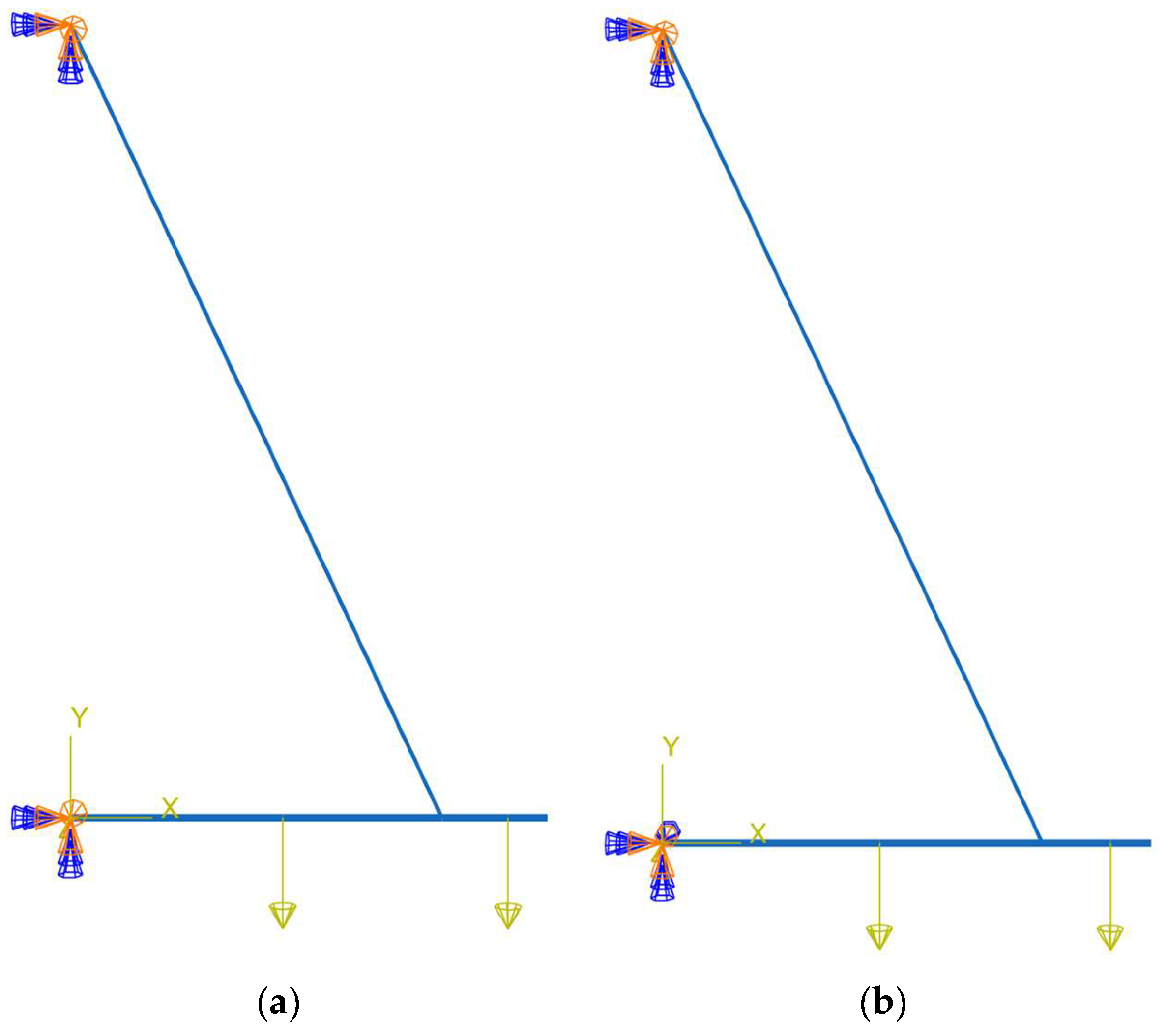
4. Validation
4.1. Validation Model
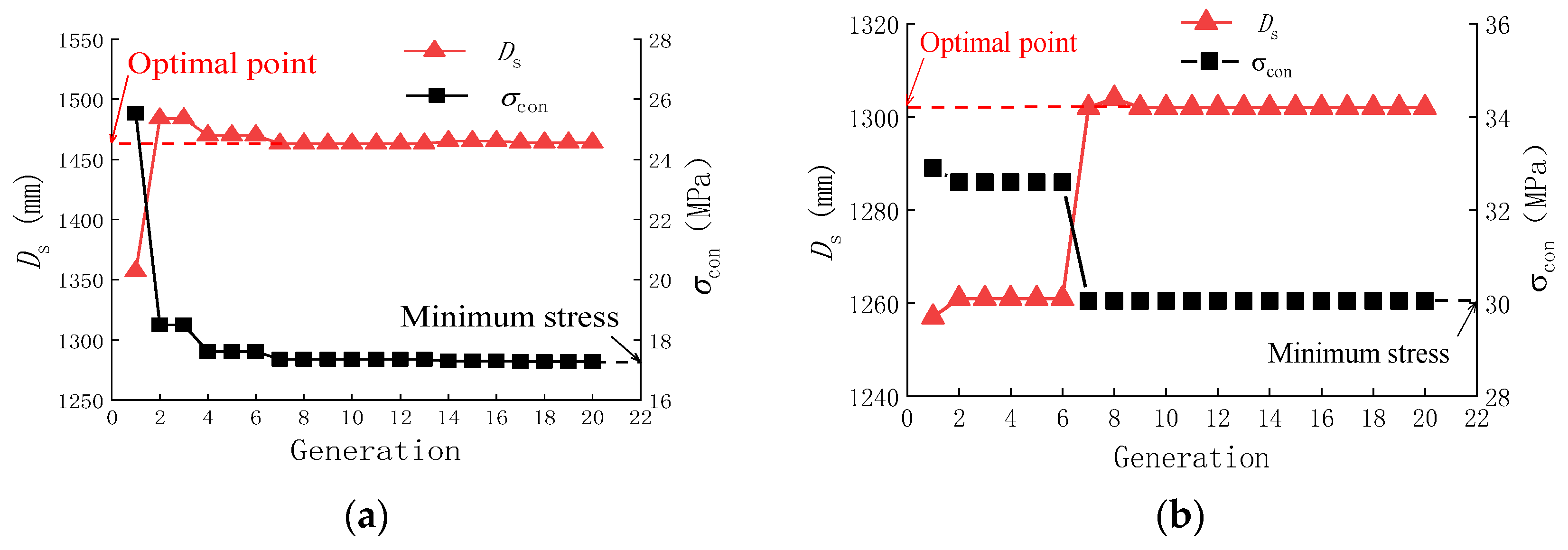
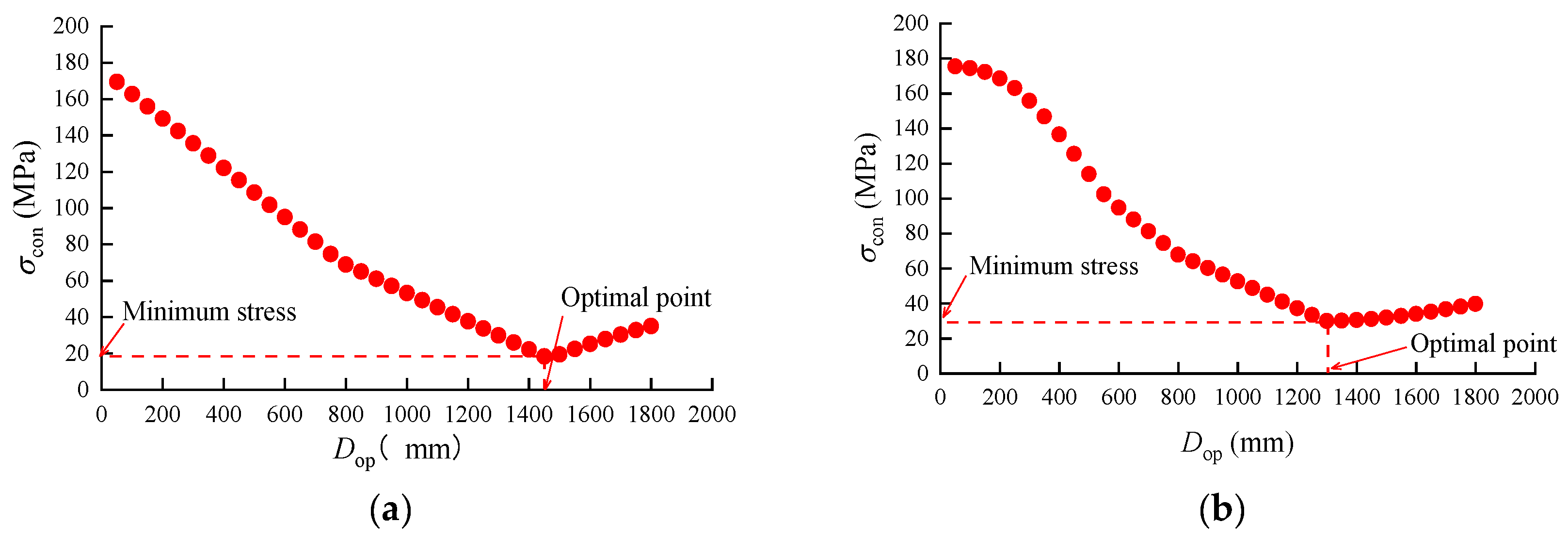
4.2. Validation Results
- (1)
- Results of the proposed methodology
- (2)
- Results of the enumeration methodology
- (3)
- Result comparison
5. Optimization Analysis
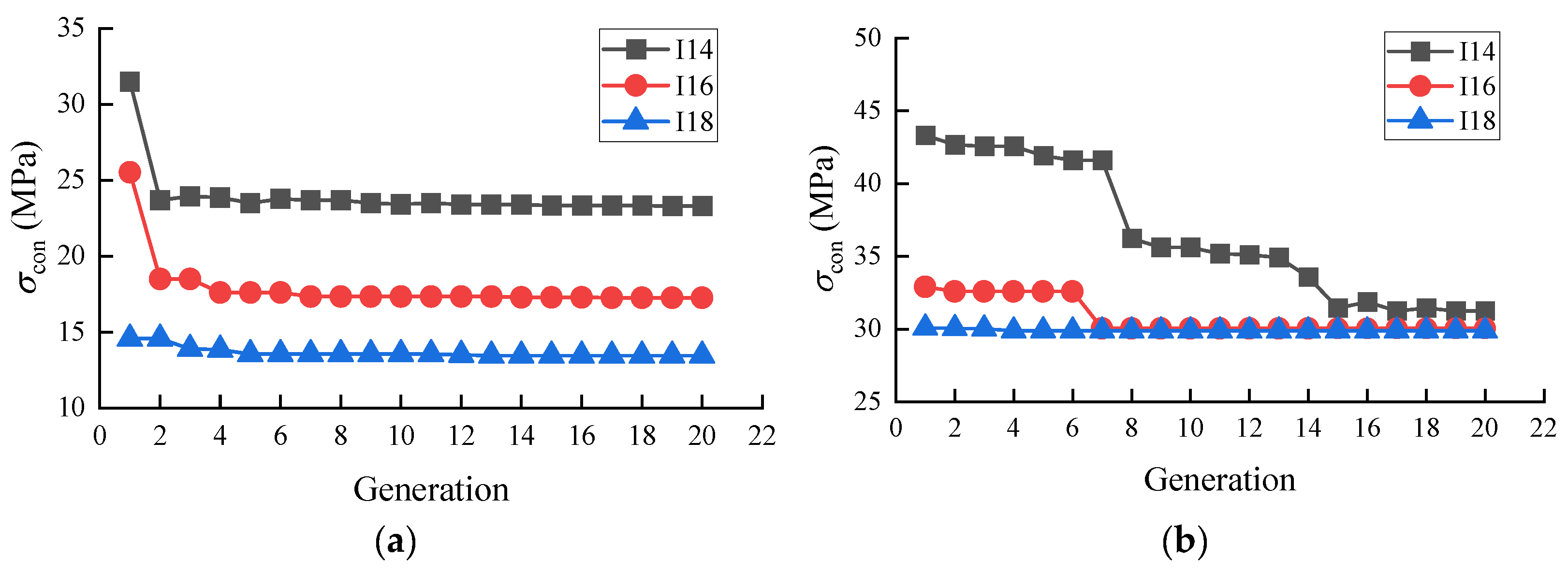
5.1. Analytical Results with Varying Beam Cross-Sections
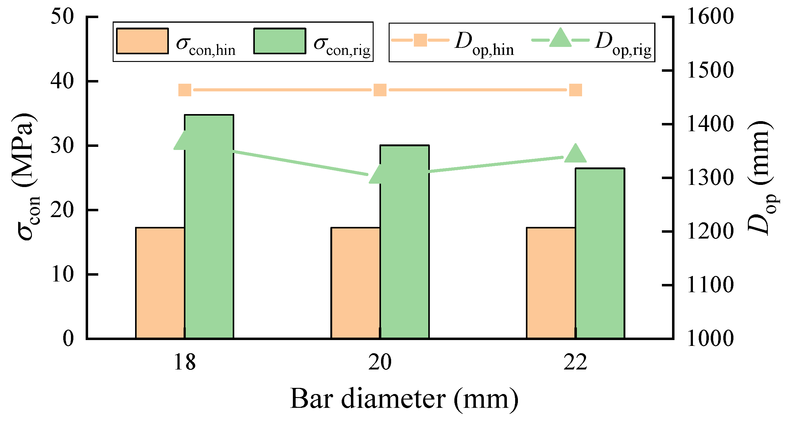
5.2. Analytical Results with Varying Bar Diameters
5.3. Analytical Results with Varying Upper Suspension Point Positions
6. Optimization Result Evaluation
6.1. Varying Beam Cross-Section
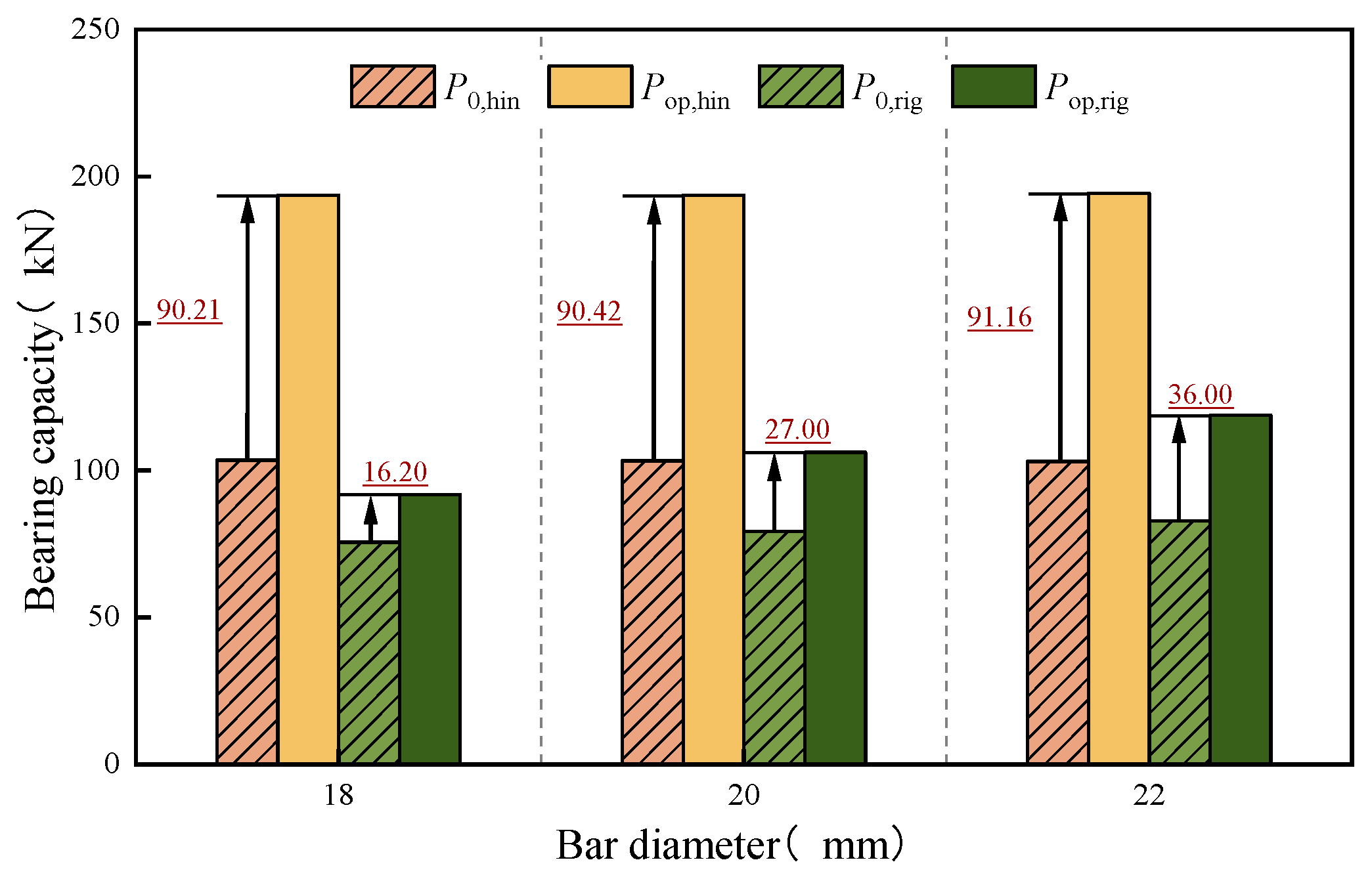
6.2. Varying Bar Diameter
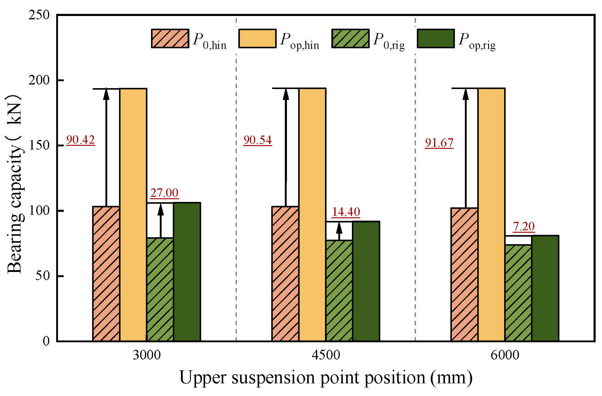
6.3. Varying Upper Suspension Point Position
7. Conclusions
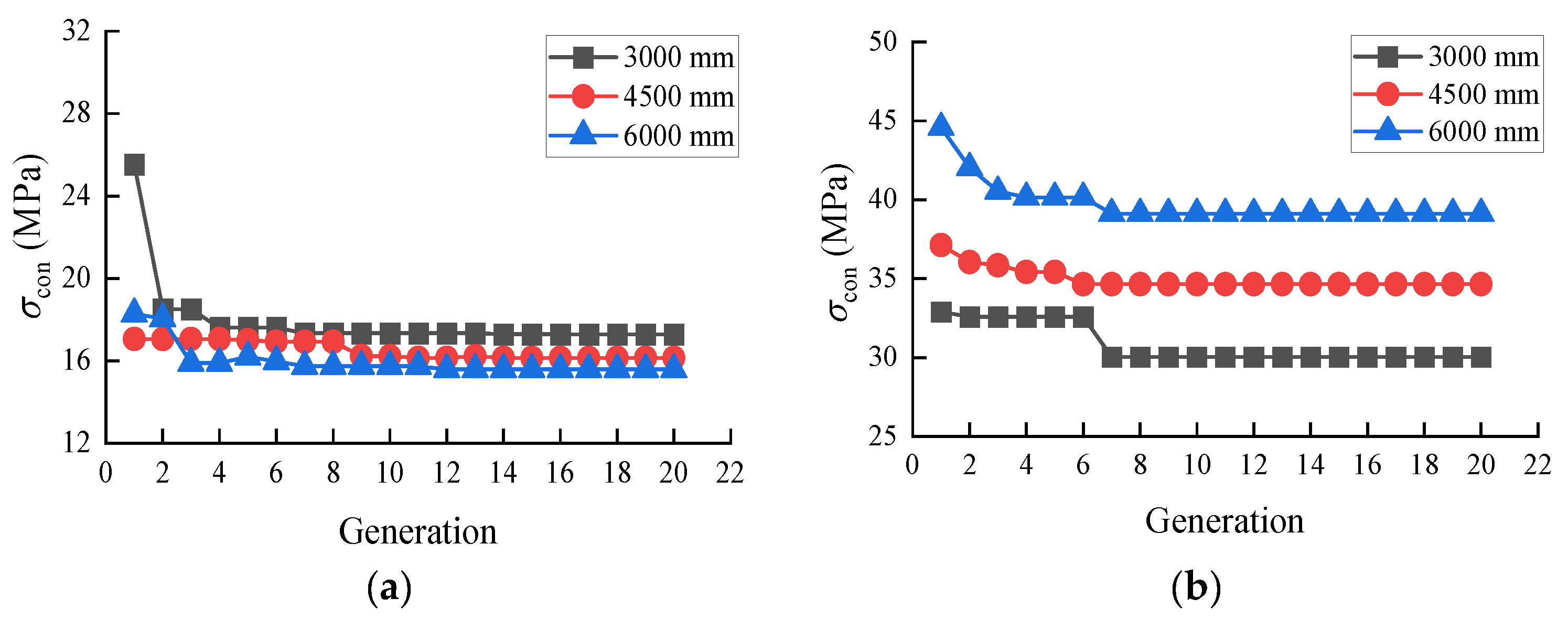
- The proposed optimization methodology is demonstrated to be an efficient and accurate way to obtain superior behavior for an attached cantilever scaffold. The convergence speed of the rigidly connected beam controlling stress is always slower than that of the beam connected by a hinge. In addition, the convergence speed could also be affected by the beam sections and upper suspension point position, especially for rigidly connected cantilever scaffolds.
- According to a parametrical analysis of the proposed optimization methodology, the optimal lower suspension point position corresponding to the hinged cantilever scaffold cannot be affected by the beam section or bar diameter. However, for a rigidly attached cantilever scaffold, it is significantly affected by the beam section and bar diameter.
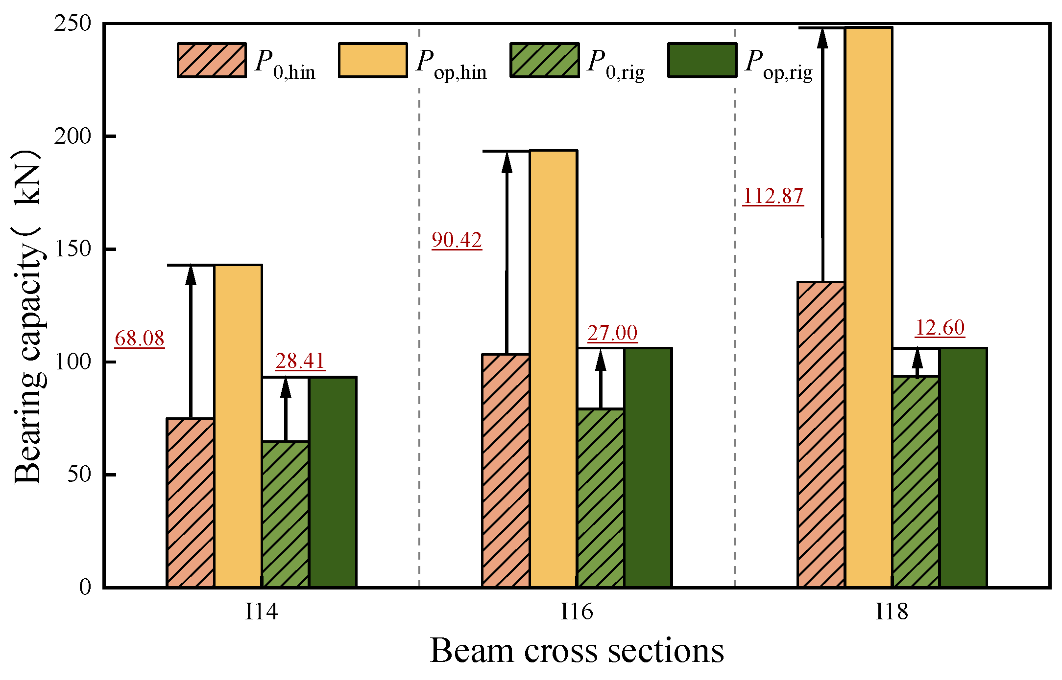
- Compared to the specification-recommended attached cantilever scaffold, the bearing capacity of the optimized ones could be significantly enhanced. The enhancement is corelated to the attached cantilever scaffold connection types. When the attached cantilever scaffold is rigidly connected, the maximum bearing capacity enhancement could reach about 100%. In contrast, the maximum enhancement is about 40% for the case when the scaffold is connected by a hinge.
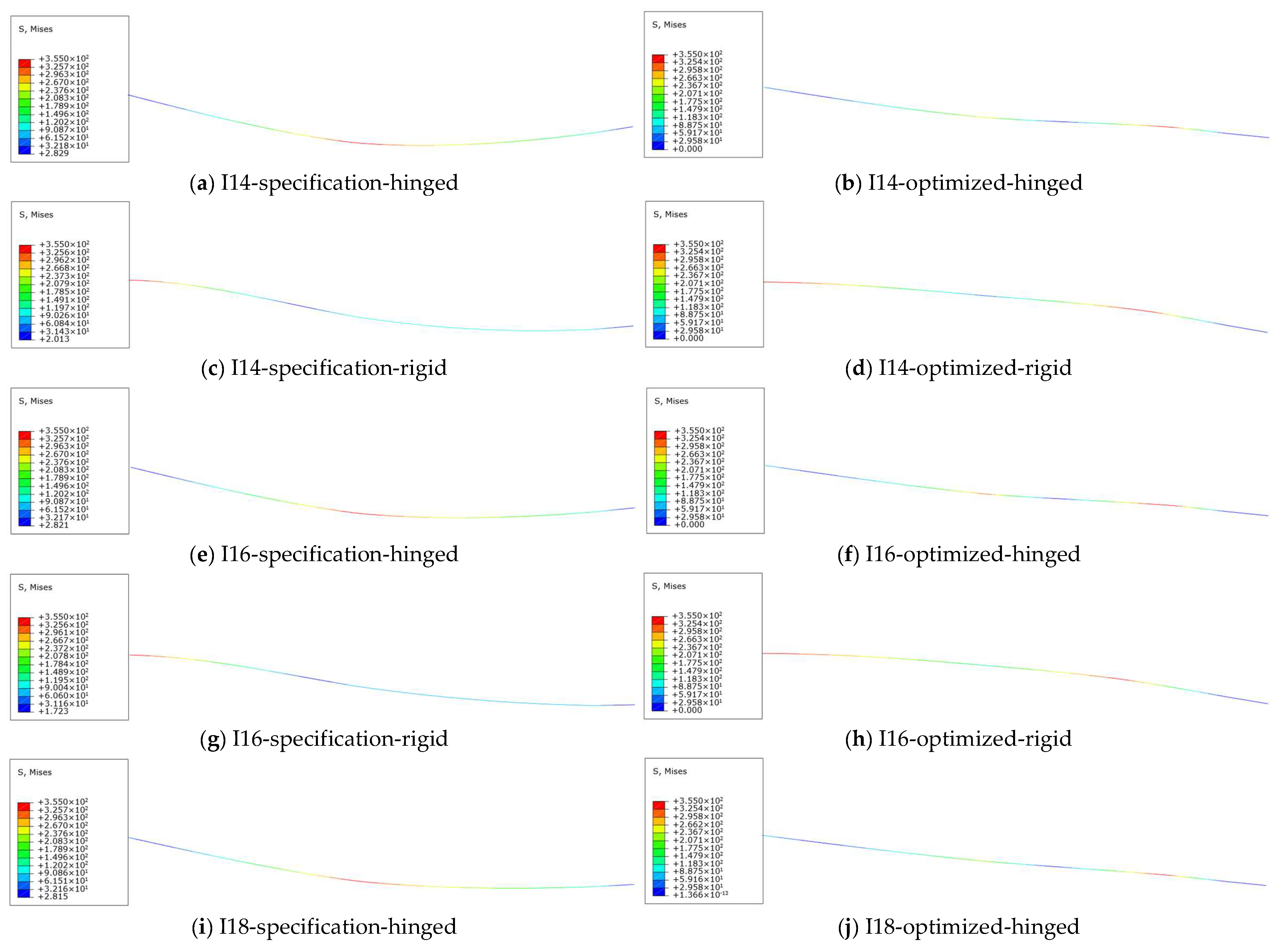
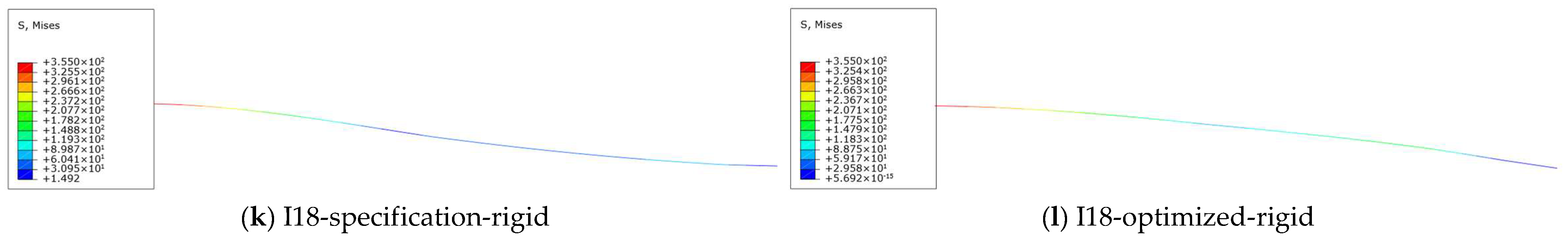
- The controlling stress of the rigidly connected beam is always greater than that of the hinged connection beams. In other words, the bearing capacity of a hinged cantilever scaffold is higher than that of a rigid one when the amount of consumed material is the same.
Author Contributions
Funding
Data Availability Statement
Conflicts of Interest
References
- Chen, F.; Wan, W.D.; Fan, Y.B.; Qi, X.H. Finite element analysis of typical fastener type full hall steel tubular scaffolds. IOP Conf. Ser. Earth Environ. Sci. 2021, 634, 012095. [Google Scholar] [CrossRef]
- DBJ/T 15-233-2021; Technical Specification for Safety of Attached Lifting Scaffold in Construction. Guangdong Provincial Department of Housing and Urban Rural Development: Guangzhou, China, 2021. (In Chinese)
- Du, Z.G. Application of allached lifting steel scaffold in the construction of high-rise buildings. China Constr. Met. Struct. 2024, 23, 103–105. (In Chinese) [Google Scholar]
- Kaewsawang, S.; Chotickai, P. Effect of bolt-tightening torques of couplers on load capacities of tube-coupler scaffolds. J. Constr. Steel Res. 2024, 214, 108496. [Google Scholar] [CrossRef]
- Jia, L.; Liu, H.; Chen, Z.; Liu, Q.; Wen, S. Mechanical properties of right-angle couplers in steel tube-coupler scaffolds. J. Constr. Steel Res. 2016, 125, 43–60. [Google Scholar] [CrossRef]
- Liu, H.; Jia, L.; Wen, S.; Liu, Q.; Wang, G.; Chen, Z. Experimental and theoretical studies on the stability of steel tube-coupler scaffolds with different connection joints. Eng. Struct. 2016, 106, 80–95. [Google Scholar] [CrossRef]
- Abdel-Jaber, M.; Abdel-Jaber, M.S.; Beale, R.G.; Allouzi, R.; Shatarat, N.K. Properties of tube and fitting scaffold connections under cyclical loads. J. Constr. Steel Res. 2020, 168, 106008. [Google Scholar] [CrossRef]
- Zheng, Y.; Guo, Z. Investigation of joint behavior of disk-lock and cuplok steel tubular scaffold. J. Constr. Steel Res. 2021, 177, 106415. [Google Scholar] [CrossRef]
- Weesner, L.B.; Jones, H.L. Experimental and analytical capacity of frame scaffolding. Eng. Struct. 2001, 23, 592–599. [Google Scholar] [CrossRef]
- Peng, J.; Chen, K.; Chan, S.; Chen, W.T. Experimental and analytical studies on steel scaffolds under eccentric loads. J. Constr. Steel Res. 2009, 65, 422–435. [Google Scholar] [CrossRef]
- Lipecki, T.; Jaminska-Gadomska, P.; Blazik-Borowa, E. Wind load on façade scaffolding without protective cover—Eurocode and in-situ measurement approaches. J. Build. Eng. 2021, 42, 102516. [Google Scholar] [CrossRef]
- Peng, J.; Ho, C.; Chan, S.; Chen, W. Stability study on structural systems assembled by system scaffolds. J. Constr. Steel Res. 2017, 137, 135–151. [Google Scholar] [CrossRef]
- Chan, J.L.Y.; Lo, S.H. Stability design of system scaffold with differential settlement. Structures 2020, 27, 1467–1478. [Google Scholar] [CrossRef]
- Chandrangsu, T.; Rasmussen, K.J.R. Structural modelling of support scaffold systems. J. Constr. Steel Res. 2011, 67, 866–875. [Google Scholar] [CrossRef]
- Chu, A.Y.T.; Zhou, Z.H.; Koon, C.M.; Chan, S.L.; Peng, J.L.; Pan, A.D. Design of Steel Scaffolding using an Integrated Design and Analysis Approach. In Advances in Steel Structures; Elsevier: Amsterdam, The Netherlands, 1996; pp. 245–250. [Google Scholar]
- Chu, A.Y.T.; Chan, S.L.; Chung, K.F. Stability of modular steels scaffolding systems—Theory and verification. In Advances in Building Technology; Elsevier: Amsterdam, The Netherlands, 2002; pp. 621–628. [Google Scholar]
- Chu, A.Y.T.; Chan, S.L. Design of Steel Scaffolding by Nonlinear Integrated Design and Analysis(NIDA) and the Stability Function. In Advances in Steel Structures; Elsevier: Amsterdam, The Netherlands, 1999; pp. 791–798. [Google Scholar]
- Chan, S.L.; Dymiotis, C.; Zhou, Z.H. Second-order analysis and design of steel scaffold using multiple eigen-imperfection modes. In Advances in Steel Structures; Elsevier: Amsterdam, The Netherlands, 2002; pp. 321–327. [Google Scholar]
- Mercier, C.; Khelil, A.; Al Mahmoud, F.; Blin-Lacroix, J.-L.; Pamies, A. Experimental investigation of buckling behavior of steel scaffolds. Structures 2021, 33, 433–450. [Google Scholar] [CrossRef]
- Chen, Z.; Lv, J.; Liu, H.; Liu, Q.; Ye, B. Experimental and analytical studies on stability of ultra-strong thin-walled steel tube and coupler scaffolds. Eng. Struct. 2023, 275, 115255. [Google Scholar] [CrossRef]
- Camp, C.; Pezeshk, S.; Cao, G.Z. Optimized Design of Two-Dimensional Structures Using a Genetic Algorithm. J. Struct. Eng. 1998, 124, 551–559. [Google Scholar] [CrossRef]
- Blazik-Borowa, E.; Borowa, A.; Kawecki, B.; Kotowicz, M.; Robak, A. Geodesic inventory of scaffolding geometry. Eng. Struct. 2019, 196, 109360. [Google Scholar] [CrossRef]
- Jian, L. Research on the application of upper tie rod cantilever scaffold in the construction of special-shaped curtain wall. Build. Constr. 2024, 46, 278–281. (In Chinese) [Google Scholar]
- Mao, J.; Guo, X.; Wu, F.; Wang, D.; Li, H. Research and application of basket pull rod cantilever scaffold construction. Build. Constr. 2021, 43, 2101–2103. (In Chinese) [Google Scholar]
- Wang, H.; Li, P.C.; Wu, M.E. Crossarm length optimization and post-buckling analysis of prestressed stayed steel columns. Thin-Walled Struct. 2019, 144, 106371. [Google Scholar] [CrossRef]
- Li, P.C.; Wang, H. A novel strategy for the crossarm length optimization of PSSCs based on multi-dimensional global optimization algorithms. Eng. Struct. 2021, 238, 112238. [Google Scholar] [CrossRef]
- Contreras-Bejarano, O.; Villalba-Morales, J.D. On the use of the differential evolution algorithm for truss-type structures optimization. Appl. Soft Comput. 2024, 161, 111372. [Google Scholar] [CrossRef]
- Zhao, Z.W.; Kang, Z.W.; Zhang, T.R.; Zhao, B.Z.; Zhang, D.C.; Yan, R.Z. Topology optimization algorithm for spatial truss based on numerical inverse hanging method. J. Constr. Steel Res. 2024, 219, 108764. [Google Scholar] [CrossRef]
- Kumar, M.; Husian, M.; Upreti, N.; Gupta, D. Genetic algorithm: Review and application. Int. J. Inf. Technol. Knowl. Manag. 2010, 2, 451–454. [Google Scholar] [CrossRef]
- Annu, L.; Kunal, G.; Kriti, C. Genetic Algorithm-A Literature Review. In Proceedings of the 2019 International Conference on Machine Learning, Big Data, Cloud and Parallel Computing, Faridabad, India, 14–16 February 2019; pp. 380–384. [Google Scholar]
- Ines, C.C.; Rokia, R.; Javier, N.G. A systematic review of genetic algorithm-based multi-objective optimisation for building retrofitting strategies towards energy efficiency. Energy Build. 2020, 210, 109690. [Google Scholar]
- DBJ50/T-426-2022; Technical Standard for Safety of Attached Cantilever Scaffold. Chongqing Housing and Urban Rural Construction Commission: Chongqing, China, 2022. (In Chinese)
- GB/T 706-2016; Hot Rolled Section Steel. Chinese Standards Institution: Beijing, China, 2017. (In Chinese)
- GB 50017-2017; Standard for Design of Steel Structures. Chinese Standards Institution: Beijing, China, 2017. (In Chinese)
- Alekseytsev, A.V.; Nadirov, S.H. Scheduling Optimization Using an Adapted Genetic Algorithm with Due Regard for Random Project Interruptions. Buildings 2022, 12, 2051. [Google Scholar] [CrossRef]
- Xie, L.; Chen, Y.; Chang, R. Scheduling Optimization of Prefabricated Construction Projects by Genetic Algorithm. Appl. Sci. 2021, 11, 5531. [Google Scholar] [CrossRef]
- Yin, H. Multi-objective optimization analysis of construction management site layout based on improved genetic algorithm. Syst. Soft Comput. 2024, 6, 200113. [Google Scholar] [CrossRef]
- Hua, Z.; Liu, Z.; Yang, L.; Yang, L. Improved Genetic Algorithm Based on Time Windows Decomposition for Solving Re-source-constrained Project Scheduling Problem. Autom. Constr. 2022, 132, 104503. [Google Scholar] [CrossRef]
- Muhlenbein, H.; Schlierkamp-Voosen, D. Predictive Models for the Breeder Genetic Algorithm. Evol. Comput. 1993, 1, 25–49. [Google Scholar] [CrossRef]


| Connection Types | Hinged | Rigid | |||
|---|---|---|---|---|---|
| Methods | Minimum Controlling Stress (MPa) | Optimal Lower Suspension Point (mm) | Minimum Controlling Stress (MPa) | Optimal Lower Suspension Point (mm) | |
| Proposed method | 17.274 | 1464 | 30.051 | 1302 | |
| Enumeration method | 18.353 | 1450 | 30.052 | 1300 | |
| Section Type | Dimensions (mm) | |||
|---|---|---|---|---|
| h | b | tw | t | |
| I14 | 140 | 80 | 5.5 | 9.1 |
| I16 | 160 | 88 | 6.0 | 9.9 |
| I18 | 180 | 94 | 6.5 | 10.7 |
Disclaimer/Publisher’s Note: The statements, opinions and data contained in all publications are solely those of the individual author(s) and contributor(s) and not of MDPI and/or the editor(s). MDPI and/or the editor(s) disclaim responsibility for any injury to people or property resulting from any ideas, methods, instructions or products referred to in the content. |
© 2024 by the authors. Licensee MDPI, Basel, Switzerland. This article is an open access article distributed under the terms and conditions of the Creative Commons Attribution (CC BY) license (https://creativecommons.org/licenses/by/4.0/).
Share and Cite
Song, S.; Zhao, Y.; Liang, F.; Guo, H.; Zhang, T.; Li, P.; Xiong, G. Optimization of Lower Suspension Point Position in Attached Cantilever Scaffold. Buildings 2024, 14, 2592. https://doi.org/10.3390/buildings14092592
Song S, Zhao Y, Liang F, Guo H, Zhang T, Li P, Xiong G. Optimization of Lower Suspension Point Position in Attached Cantilever Scaffold. Buildings. 2024; 14(9):2592. https://doi.org/10.3390/buildings14092592
Chicago/Turabian StyleSong, Shushuang, Ying Zhao, Fei Liang, Hu Guo, Tianhao Zhang, Pengcheng Li, and Gang Xiong. 2024. "Optimization of Lower Suspension Point Position in Attached Cantilever Scaffold" Buildings 14, no. 9: 2592. https://doi.org/10.3390/buildings14092592