
Thermal and Structural Performances of Screen Grid Insulated Concrete Forms (SGICFs) Using Experimental Testing


Abstract
:1. Introduction
2. Specimen Preparation and Test Methods
2.1. Specimen Preparation
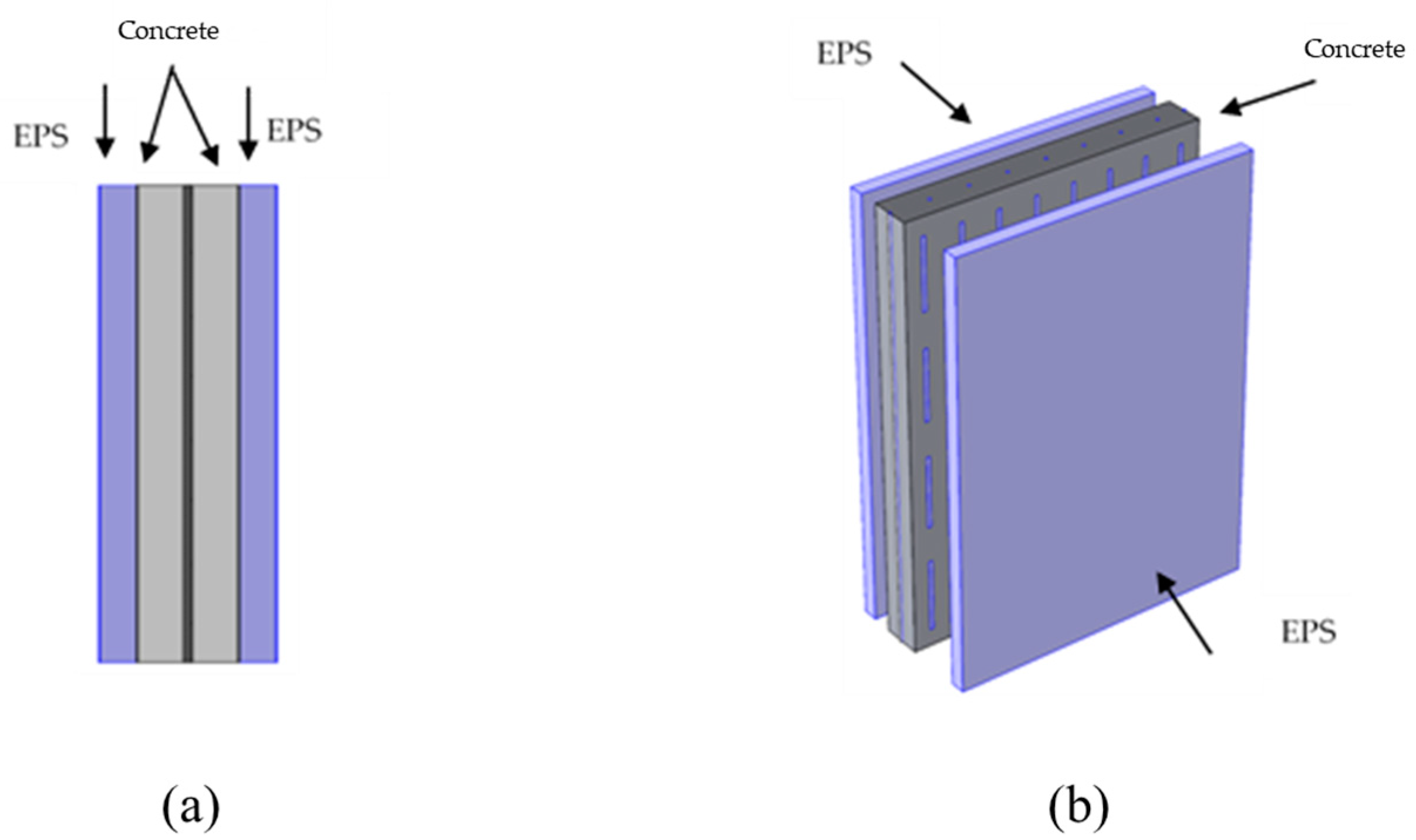
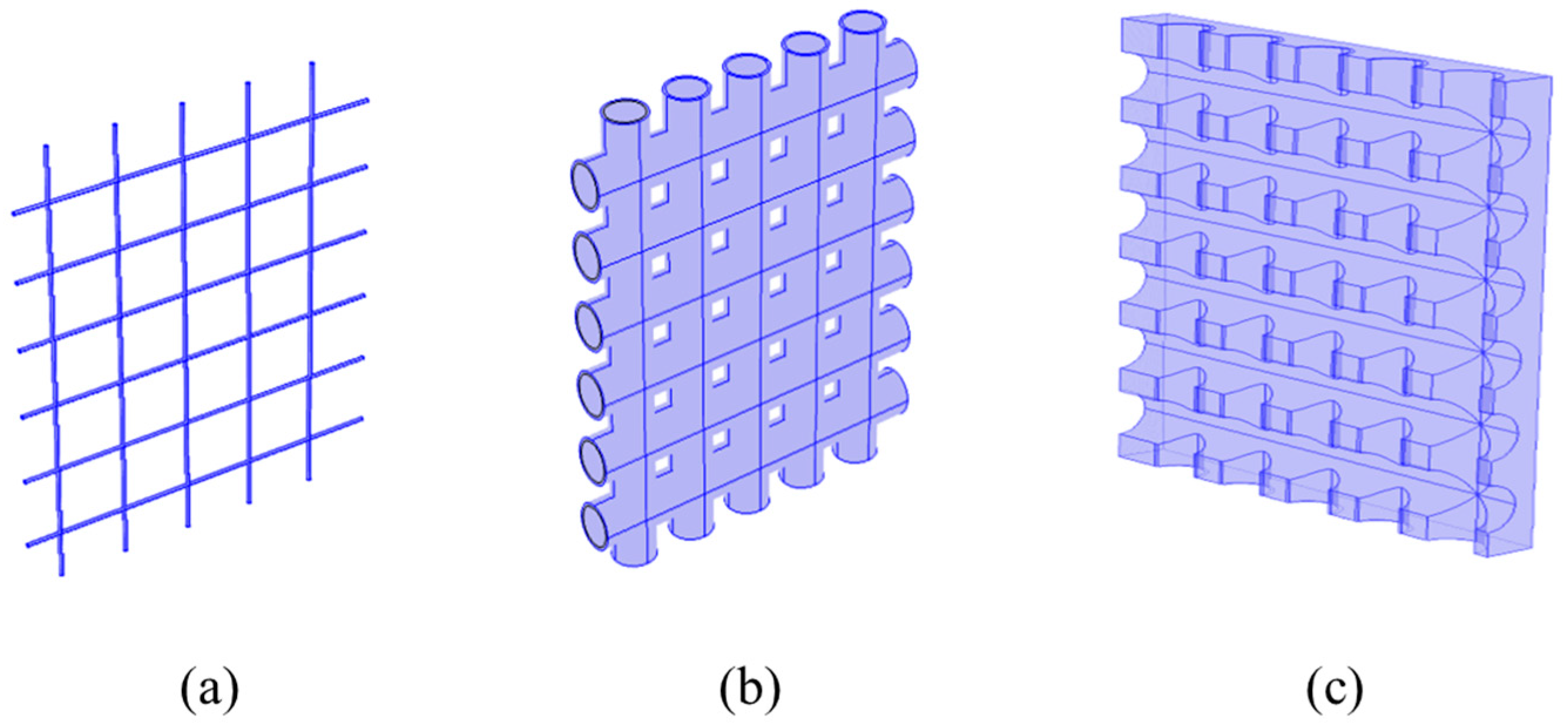
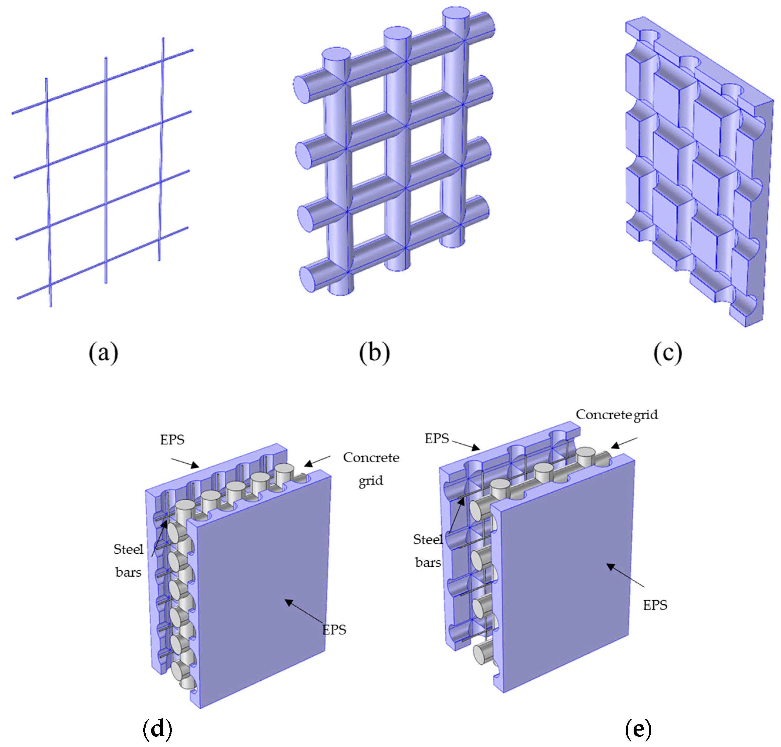
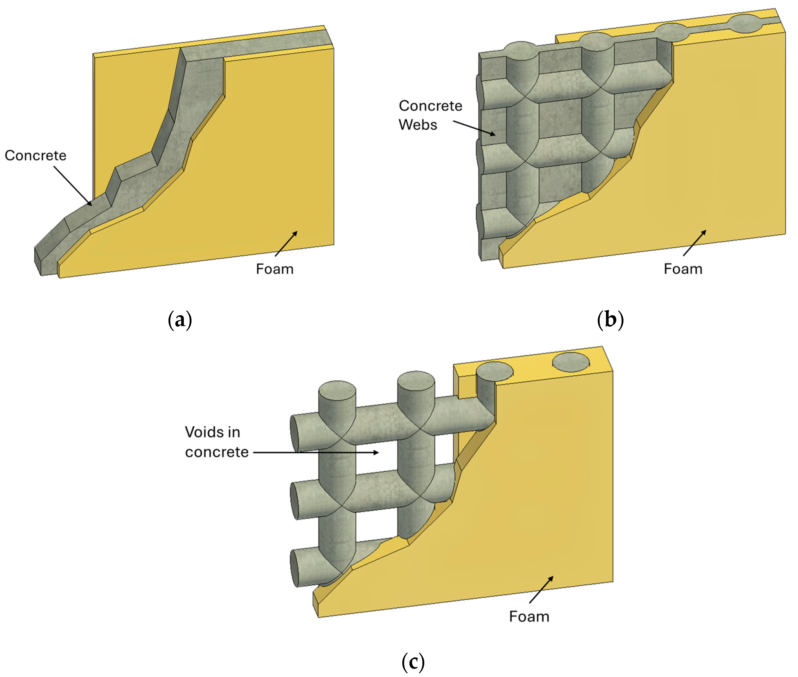
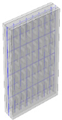
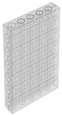
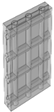
2.1.1. ICF Walls


| Dimension Parameters | |||
|---|---|---|---|
| Thickness of the EPS layer (m) | 0.06 | 0.05 | 0.05 |
| Height of the wall (m) | 1.62 | 1.49 | 1.49 |
| Width of the wall (m) | 1.2 | 1.24 | 1.24 |
| Thickness of the concrete layer (m) | 0.16 | 5 6 SGICF | 3 4 SGICF |
| Material Type | EPS | Concrete | Polypropylene | Steel |
|---|---|---|---|---|
| Density | 24.02 | 2400 | 900 | 7850 |
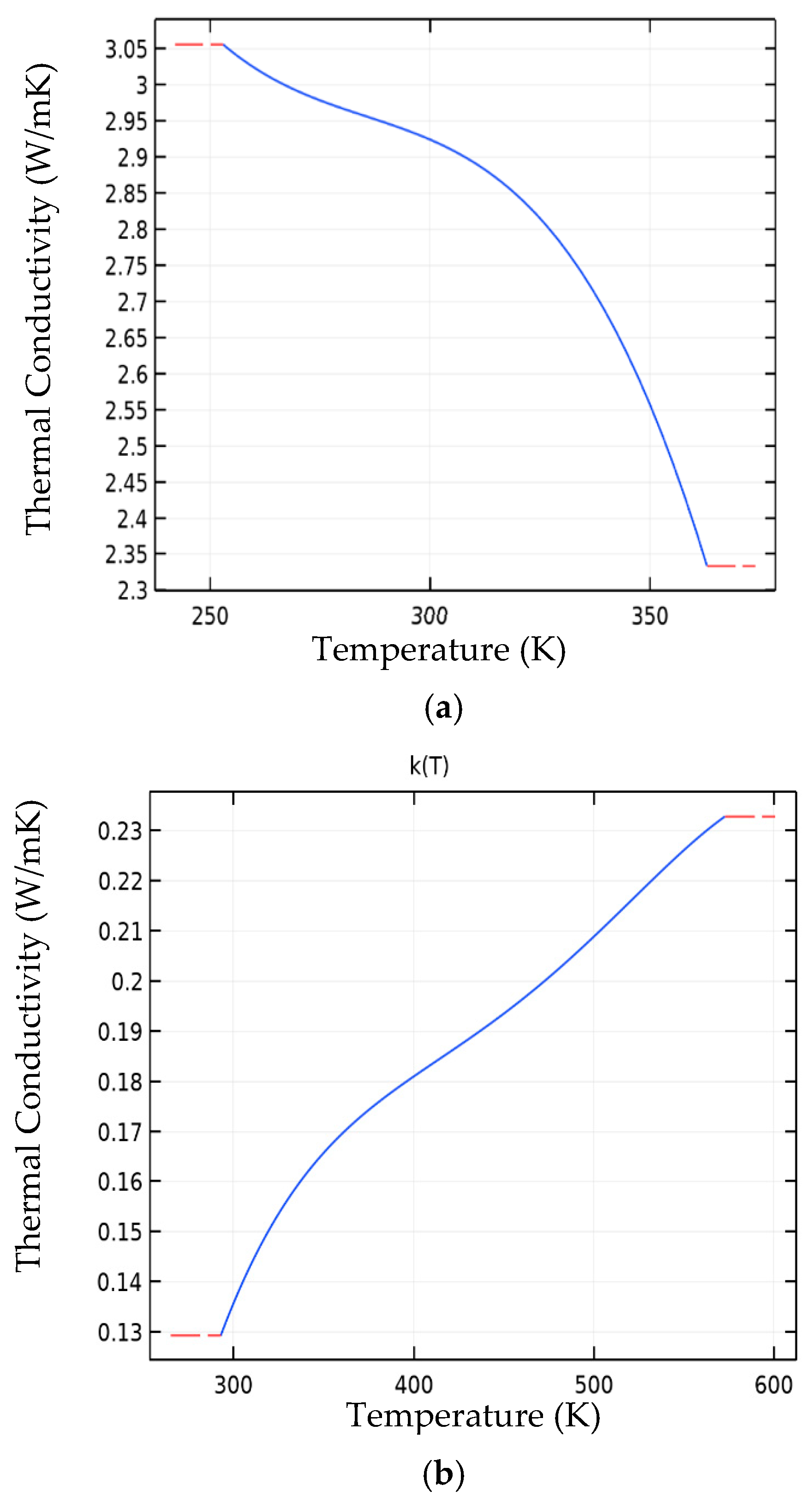
| Thermal conductivity | 0.03 | Figure 9a 1 | Figure 9b 2 | 44.5 |
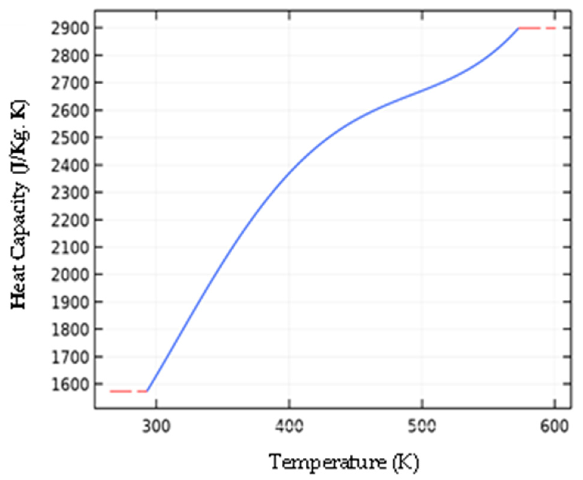
| Heat capacity J/kg | 1300 | 880 | Figure 10 3 | 475 |
2.1.2. Typical Brick Walls
- Wall : 2.5 cm Plaster layer + 20 cm Brick layer + 5 cm Extruded polystyrene insulation layer + 1.3 Plaster Gypsum Wall Board (GWB) and Paint layer.
- Wall : 2.5 cm Plaster layer + 20 cm Brick layer + 2.5 cm Plaster layer.
- Wall : 2.5 cm Plaster layer + 10 cm Brick layer + 2.5 cm Plaster layer.
2.2. Test Methods
2.2.1. Simulation Model
- Defining the dimensions and location of all layers in the modeled wall elements;
- Defining the physical properties (specific heat capacity, thermal conductivity, density) of all layers in the model elements;
- Defining the initial and boundary conditions;
- Recording the U values and thermal masses for all wall types.
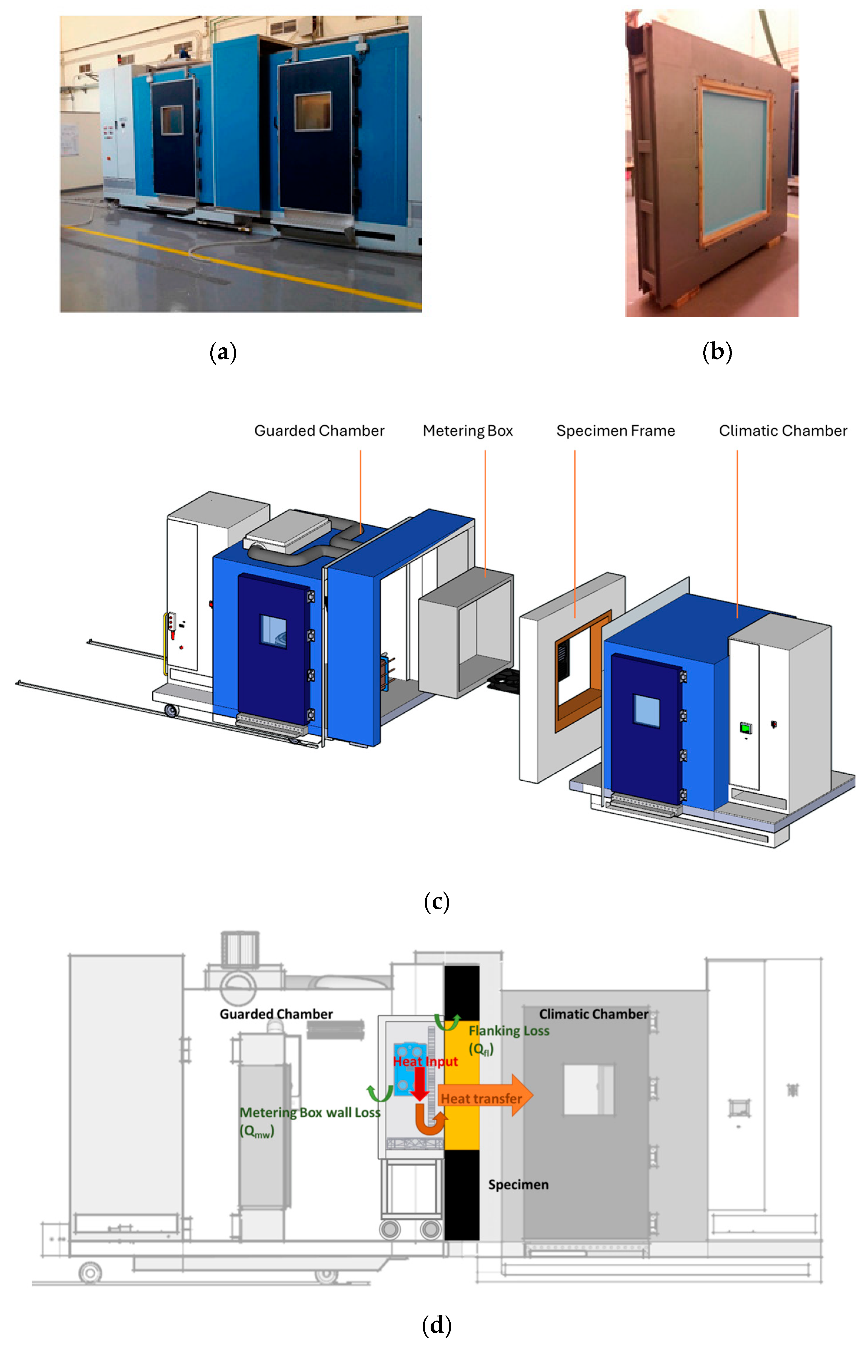
2.2.2. Experimental Setup
- Chamber structure;
- Air treatment unit;
- Cooling plant;
- Control system;
- Pre-tempering chamber;
- Special wall;
- Metering box;
- Measurement system.
3. Results
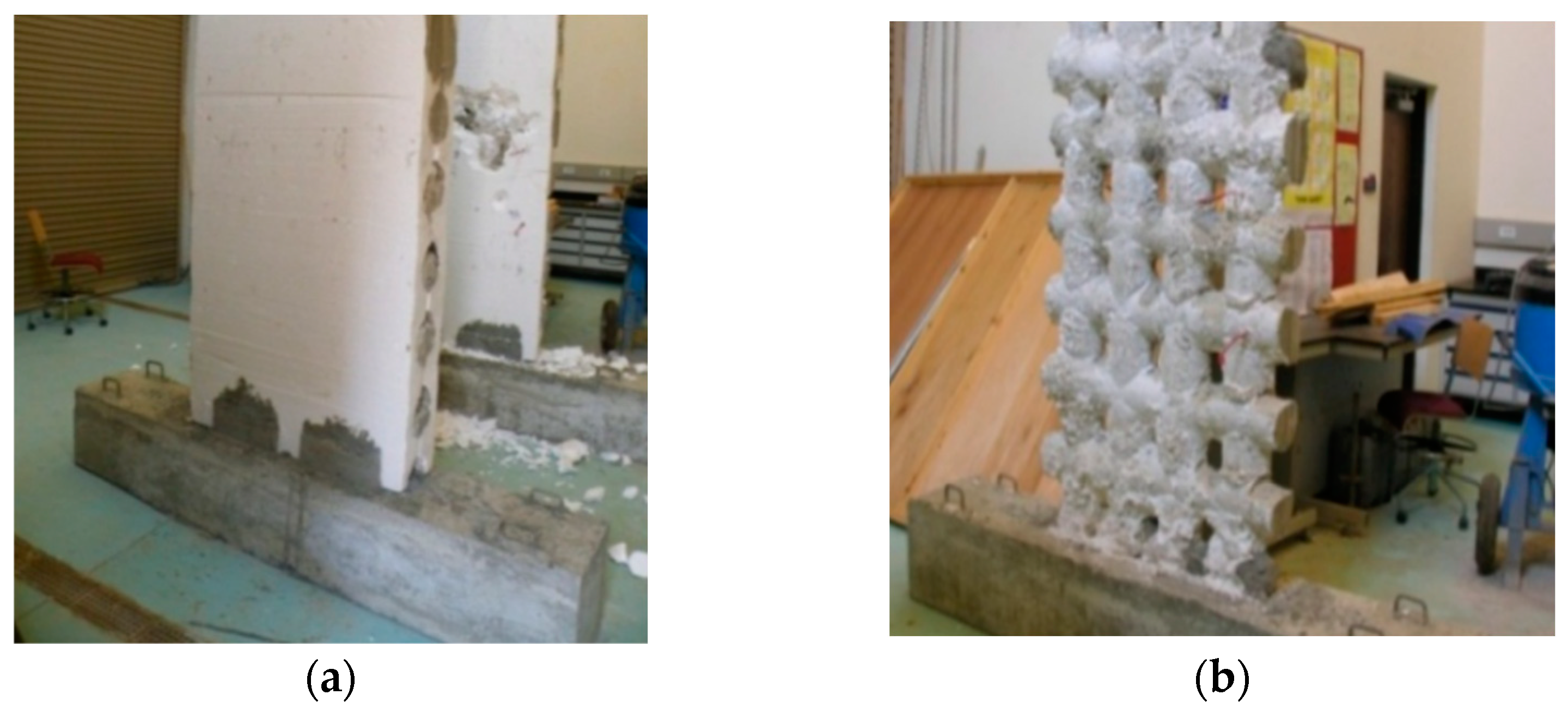
3.1. Experimental Results
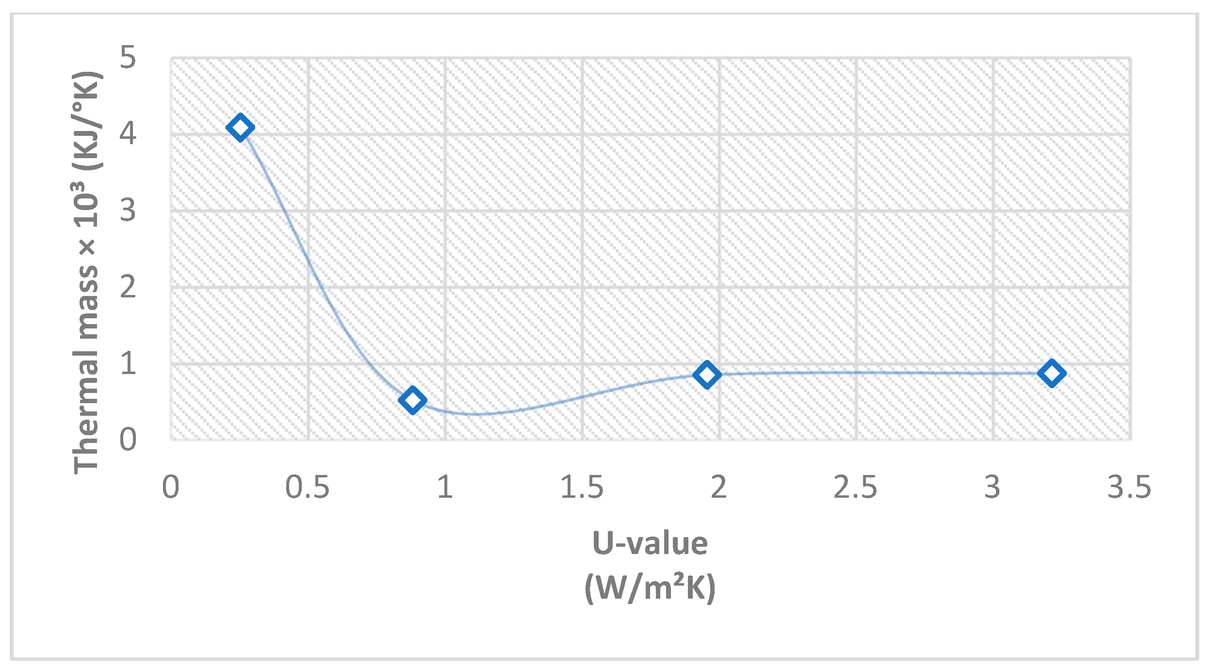
3.2. U-Value Calculations
4. Conclusions
- Energy efficiency. The study provides detailed insights into the thermal performance of SGICF walls compared to flat ICF walls and typical brick walls used in the Middle East. By demonstrating that SGICF walls offer comparable thermal insulation properties with a potentially lower thermal mass, this research highlights the viability of SGICF wall systems in hot climates where energy efficiency is paramount. This can lead to significant reductions in energy consumption for heating and cooling, contributing to sustainability goals and cost savings for building owners.
- Structural resilience. In addition to thermal performance, the study underscores the structural benefits of SGICF walls. The grid pattern of concrete in SGICF systems offers a robust framework that can enhance the durability and seismic performance of buildings. This is particularly relevant in regions prone to seismic activity, where the adoption of SGICFs is structurally sound.
- Economic and environmental impact. The use of SGICFs can reduce the overall material costs due to the lower volume of concrete required. Additionally, the environmental impact is minimized as the system reduces the need for traditional formwork and promotes the use of recyclable materials like EPS. This aligns with global trends towards greener construction practices and supports efforts to mitigate the environmental footprint of the construction industry.
- Practical applications. The findings from this research can inform best practices and guide the development of building codes and standards that incorporate SGICF technology. Practitioners in the construction industry, including architects, engineers, and builders, can leverage the insights from this study to design and construct more efficient and resilient buildings. Moreover, policymakers and regulators can use this evidence to support the adoption of innovative construction techniques that promote sustainability and resilience.
Author Contributions
Funding
Data Availability Statement
Conflicts of Interest
References
- Abdel-Mooty, M.; Haroun, M.; El Maghraby, Y.; Fahmy, E.; Abou Zeid, M. Performance of screen grid insulating concrete form walls under combined in-plane vertical and lateral loads. Adv. Mat. Res. 2010, 163–167, 1803–1810. [Google Scholar] [CrossRef]
- Koci, R. The ABCs of ICFs, A review. Canadian Contractor, 17 September 2013. [Google Scholar]
- Nowak, M.; Davis, P. Costs, sound, and energy performance of ICF homes. In Construction Congress VI; American Society of Civil Engineers: Reston, VA, USA, 2000; pp. 898–907. [Google Scholar] [CrossRef]
- Ngugi, H.N.; Kaluli, J.W.; Abiero-Gariy, Z. Use of expanded polystyrene technology and materials recycling for building construction in Kenya. Am. J. Eng. Technol. Manag. 2017, 2, 64. [Google Scholar] [CrossRef]
- Werner, C. Cyclic Behavior of Screen Grid Insulated Concrete Form Components. Master’s Thesis, Portland State University, Portland, OR, USA, 2000. [Google Scholar] [CrossRef]
- Asadi, P.; Madandoust, R.; Zahrai, S.M. Response modification factor due to ductility of screen-grid ICF wall system in high seismic risk zones. KSCE J. Civ. Eng. 2017, 21, 258–264. [Google Scholar] [CrossRef]
- Dusicka, P.; Kay, T. In-plane lateral cyclic behavior of insulated concrete form grid walls. J. Struct. Eng. 2011, 137, 1075–1084. [Google Scholar] [CrossRef]
- In-Plane Shear Resistance of Insulating Concrete Form Walls; NAHB: Upper Marlboro, MD, USA, 2001.
- Kari, B.M.; Jahromi, K.K. Insulating Concrete Forms; Housing and Building Research Center Publications: Tehran, Iran, 2010. [Google Scholar]
- Eman, M.; Elsayed, A. Structural behaviour of insulated concrete form (ICF) walls in comparison to traditional types of bearing walls. Al Azhar Univ. Civ. Eng. Res. Mag. (CERM) 2019, 41, 65–76. [Google Scholar]
- Lopez, A.; Bazaez, R.; Leiva, G.; Loyola, R.; Gómez, M. Experimental study of in-plane flexural behavior of screen-grid insulated concrete form rectangular and T-shaped walls. Eng. Struct 2021, 247, 113128. [Google Scholar] [CrossRef]
- Kosny, J.; Kossecka, E.; Desjarlais, A.O.; Christian, J.E. Dynamic thermal performance of concrete and masonry walls. In Thermal Performance of the Exterior Envelopes of Buildings VII; American Society of Heating, Refrigerating and Air-Conditioning Engineers: Atlanta, GA, USA, 1998; pp. 629–643. [Google Scholar]
- Kosny, J.; Petrie, T.; Gawin, D.; Childs, P.; Desjarlais, A.; Christian, J. Energy benefits of application of massive walls in residential buildings. In Proceedings of the Thermal Performance of the Exterior Envelopes of Buildings VIII, Clearwater Beach, FL, USA, 2–7 December 2001. [Google Scholar]
- Colantonio, A. Thermal performance patterns on solid masonry exterior walls of historic buildings. J. Therm. Insul. Build. Envel. 1997, 21, 185–201. [Google Scholar] [CrossRef]
- Petire, T.; Kosny, J.; Desjarlais, A.; Atchley, J.; Childs, P.W.; Ternes, M.P.; Christian, J.E. How Insulating Concrete Form vs. Conventional Construction of Exterior Walls Affects Whole Building Energy Consumption: Results from a Field Study and Simulation of Side-by-Side Houses; Residential Buildings: Technologies, Design, Performance Analysis, and Building Industry Trends; Oak Ridge National Laboratory, ORNL: Oak Ridge, TN, USA, 2003; pp. 1235–1246. [Google Scholar]
- Kosny, J.; Petrie, T.; Gawin, D.; Childs, P.; Desjarlais, A.; Christian, J. Thermal Mass-Energy Savings Potential in Residential Buildings; Buildings Technology Center, ORNL: Oak Ridge, TN, USA, 2001. [Google Scholar]
- Armstrong, M.; Saber, H.H.; Maref, W.; Rousseau, M.Z.; Ganapathy, G.; Swinton, M.C. Field Energy Performance of an Insulating Concrete form (ICF) Wall; Natural Resources Canada: Winnipeg, MB, Canada, 2011. [Google Scholar]
- OSTI. The Harmonization of Canadian and U.S. Window Programs and Standards; Final Report; Enermodal Engineering, Inc.: Denver, CO, USA, 1995. [Google Scholar] [CrossRef]
- Saber, H.H.; Maref, W.; Armstrong, M.M.; Swinton, M.C.; Rousseau, M.Z.; Ganapathy, G. 3D thermal model for predicting the thermal response of insulating concrete form (ICF) wall. In Proceedings of the Thermal Performance of the Exterior Envelopes of Whole Buildings XI, Clearwater, FL, USA, 1–5 December 2010; pp. 1–21. [Google Scholar]
- Saber, H.H.; Maref, W.; Armstrong, M.M.; Swinton, M.C.; Rousseau, M.Z.; Gnanamurugan, G. Report IRC-RR-310: Numerical Simulations to Predict the Thermal Response of Insulating Concrete Form (ICF) Wall in Cold Climate; NRC Institute for Research in Construction: Ottawa, ON, Canada, 2011. [Google Scholar]
- COMSOL Multiphysics 2019. Available online: https://www.comsol.com/products (accessed on 13 August 2024).
- Kanagaraj, B.; Kiran, T.; Gunasekaran, J.; Nammalvar, A.; Arulraj, P.; Gurupatham, B.G.A.; Roy, K. Performance of sustainable insulated wall panels with geopolymer concrete. Materials 2022, 15, 8801. [Google Scholar] [CrossRef] [PubMed]
- Tarabieh, K.; Aboulmagd, A. Thermal performance evaluation of common exterior residential wall types in Egypt. Buildings 2019, 9, 95. [Google Scholar] [CrossRef]
- Asdrubali, F.; D’Alessandro, F.; Baldinelli, G.; Bianchi, F. Evaluating in situ thermal transmittance of green buildings masonries—A case study. Case Stud. Constr. Mater. 2014, 1, 53–59. [Google Scholar] [CrossRef]
- Lucchi, E. Thermal transmittance of historical brick masonries: A comparison among standard data, analytical calculation procedures, and in situ heat flow meter measurements. Energy Build 2017, 134, 171–184. [Google Scholar] [CrossRef]
- Vladimir, G.; Michal, O.; Radim, P.; Martin, Z. Benchmark of COMSOL Multiphysics via in-depth floor slab test–transient cases. Energy Procedia 2012, 14, 744–749. [Google Scholar] [CrossRef]
- Baghban, M.H.; Hovde, P.J.; Gustavsen, A. Numerical simulation of a building envelope with high performance materials. In Proceedings of the COMSOL Conference, Paris, France, 29–30 October 2010; pp. 1–5. [Google Scholar]
- Asdrubali, F.; Pisello, A.L.; D’Alessandro, F.; Bianchi, F.; Fabiani, C.; Cornicchia, M.; Rotili, A. Experimental and numerical characterization of innovative cardboard based panels: Thermal and acoustic performance analysis and life cycle assessment. Build Env. 2016, 95, 145–159. [Google Scholar] [CrossRef]
- Gerlich, V.; Sulovská, K.; Zálešák, M. COMSOL Multiphysics validation as simulation software for heat transfer calculation in buildings: Building simulation software validation. Measurement 2013, 46, 2003–2012. [Google Scholar] [CrossRef]
- Nardi, I.; Perilli, S.; de Rubeis, T.; Sfarra, S.; Ambrosini, D. Influence of insulation defects on the thermal performance of walls. Exp. Numer. Investig. J. Build. Eng. 2019, 21, 355–365. [Google Scholar] [CrossRef]
- Seitz, S.; MacDougall, C. Design of an affordable hot box testing apparatus. In Proceedings of the 16th NOCMAT Non-Conventional Materials and Technologies, Winnipeg, MB, Canada, 10–13 August 2015. [Google Scholar]
- Mero, C.R. Design and Construction of a Guarded Hot Box Facility for Evaluating the Thermal Performance of Building Wall Materials. Master’s Thesis, Texas A&M University, College Station, TX, USA, 2012. [Google Scholar]
- Schumacher, C.J.; Straube, J.F.; Ober, D.G.; Grin, A.P. Development of a new hot box apparatus to measure building enclosure thermal performance. In Proceedings of the Thermal Performance of the Exterior Envelopes of Whole Buildings XII International Conference, Clearwater, FL, USA, 1–5 December 2013; ASHRAE: Peachtree Corners, GA, USA, 2013; pp. 1–19. [Google Scholar]
- Angelantoni Test Technologies. Available online: https://www.acstestchambers.com/en (accessed on 13 August 2024).
- ASTM C1356-11; Standard Test Method for Thermal Performance of Building Materials and Envelope Assemblies by Means of a Hot Box Apparatus. ASTM International: West Conshohocken, PA, USA, 2015; pp. 775–818.
- ISO 8990; Thermal Insulation Determination of Steady-State Thermal Transmission Properties—Calibrated and Guarded Hot Box. International Organization for Standardization (ISO): Geneva, Switzerland, 1994.
- Chen, F.; Wittkopf, S.K. Summer condition thermal transmittance measurement of fenestration systems using calorimetric hot box. Energy Build. 2012, 53, 47–56. [Google Scholar] [CrossRef]


| Material Type | Brick | Concrete Plaster | Extruded-Polystyrene Board | Gypsum Wall Board |
|---|---|---|---|---|
| Density | 2000 | 2300 | 34 | 574 |
| Thermal conductivity | 0.5 | 1.8 | 0.041 | 0.27 |
| Heat capacity at constant pressure J/kg | 900 | 880 | 1450 | 1100 |
| Property | ||
|---|---|---|
 |  | |
| Experimental U-value | 2.652 | 0.304 |
| Numerical U-value | 3.216 (+21.25%) | 0.254 (−16.4%) |
| Thickness (cm) | 15 | 28 |
| Area (cm2) | 1.8476 | 1.944 |
| Property | ||||||
|---|---|---|---|---|---|---|
 |  |  |  |  |  | |
| Numerical U-value | 0.254 | 0.358 | 0.280 | 0.556 | 1.957 | 3.216 |
| K-value | 0.093 | 0.170 | 0.489 | |||
| Thermal mass | 4.085 | 0.679 | 0. 491 | 0.871 | 0.850 | 0.519 |
Disclaimer/Publisher’s Note: The statements, opinions and data contained in all publications are solely those of the individual author(s) and contributor(s) and not of MDPI and/or the editor(s). MDPI and/or the editor(s) disclaim responsibility for any injury to people or property resulting from any ideas, methods, instructions or products referred to in the content. |
© 2024 by the authors. Licensee MDPI, Basel, Switzerland. This article is an open access article distributed under the terms and conditions of the Creative Commons Attribution (CC BY) license (https://creativecommons.org/licenses/by/4.0/).
Share and Cite
El-Maghraby, Y.; Tarabieh, K.; Sharkass, M.; Mashaly, I.; Fahmy, E. Thermal and Structural Performances of Screen Grid Insulated Concrete Forms (SGICFs) Using Experimental Testing. Buildings 2024, 14, 2599. https://doi.org/10.3390/buildings14092599
El-Maghraby Y, Tarabieh K, Sharkass M, Mashaly I, Fahmy E. Thermal and Structural Performances of Screen Grid Insulated Concrete Forms (SGICFs) Using Experimental Testing. Buildings. 2024; 14(9):2599. https://doi.org/10.3390/buildings14092599
Chicago/Turabian StyleEl-Maghraby, Yosra, Khaled Tarabieh, Meral Sharkass, Islam Mashaly, and Ezzat Fahmy. 2024. "Thermal and Structural Performances of Screen Grid Insulated Concrete Forms (SGICFs) Using Experimental Testing" Buildings 14, no. 9: 2599. https://doi.org/10.3390/buildings14092599
APA StyleEl-Maghraby, Y., Tarabieh, K., Sharkass, M., Mashaly, I., & Fahmy, E. (2024). Thermal and Structural Performances of Screen Grid Insulated Concrete Forms (SGICFs) Using Experimental Testing. Buildings, 14(9), 2599. https://doi.org/10.3390/buildings14092599