
Study on the Mechanical Properties and Durability of Tunnel Lining Concrete in Coastal Areas

Abstract
:1. Introduction
2. Materials and Methods
2.1. Test Preparation
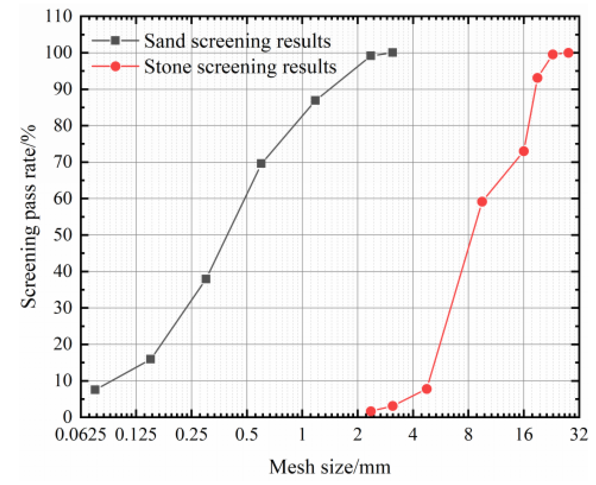
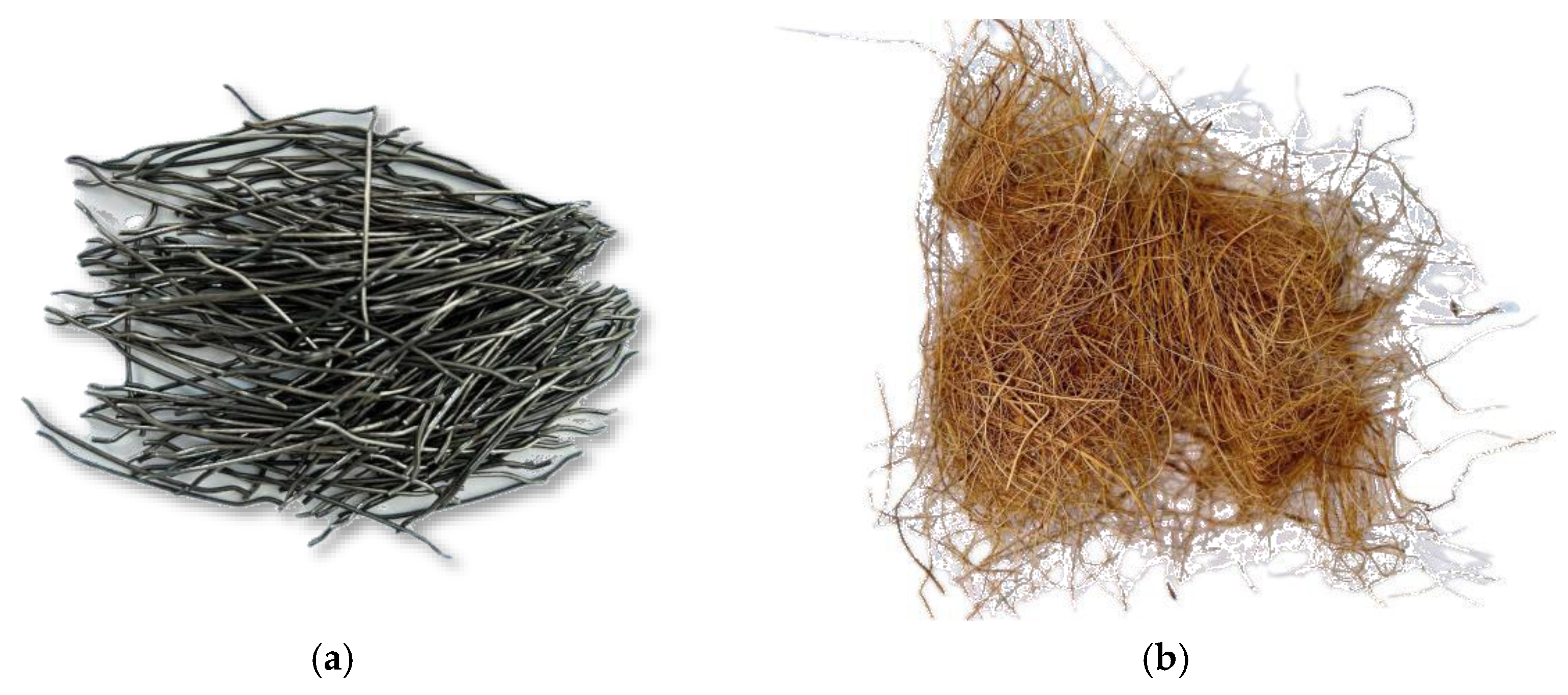
2.1.1. Raw Materials
2.1.2. Mixing Ratio
2.1.3. Preparation of Specimens
2.2. Test Methods
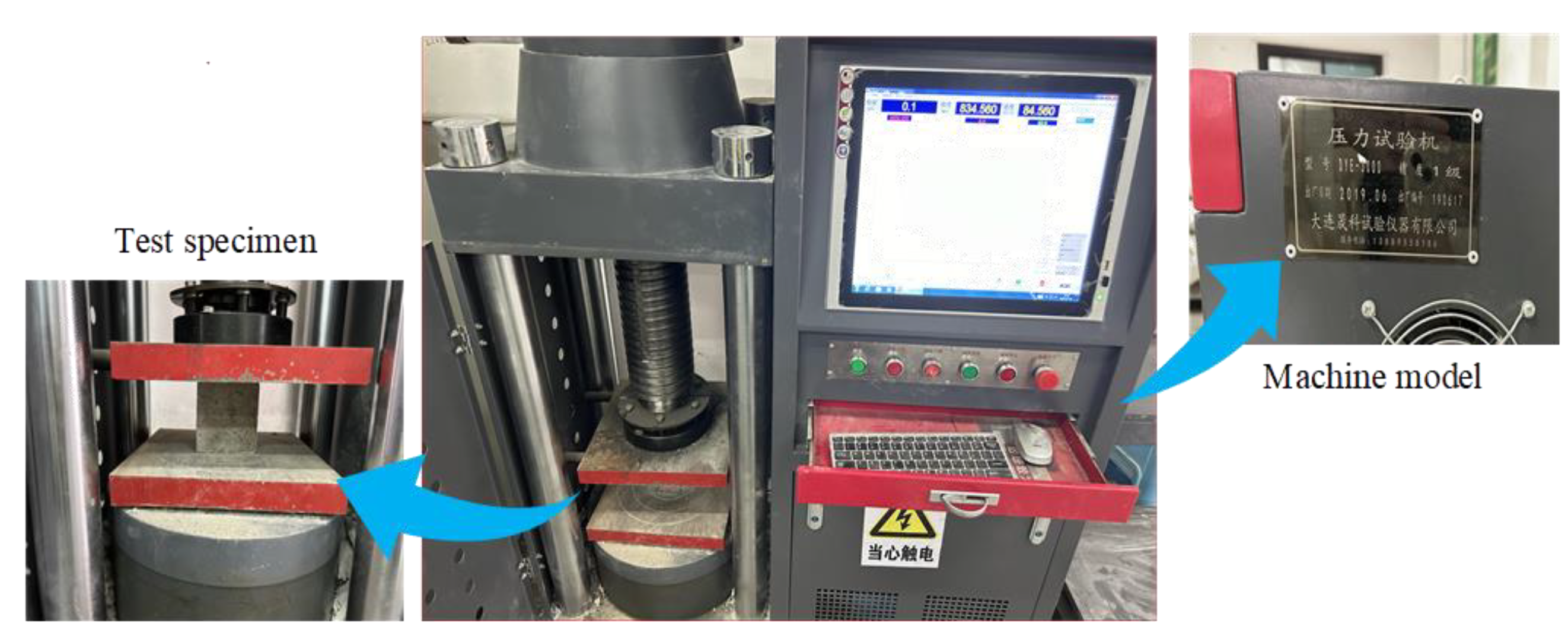
2.2.1. Compression Test, Splitting Tensile Test, and Flexural Test
- (1)
- The principle of the compressive strength test is as follows:where fcc represents the compressive strength (MPa) of the concrete cube specimens, with calculation results that should be accurate to 0.1 MPa, F represents the failure load of the specimen (N) and A represents the compressive area of the specimen (mm2).
- (2)
- The principle of splitting tensile strength test is as follows:where fts represents the splitting tensile strength of concrete (MPa), F′ indicates the failure load of the specimen (N), and A′ represents the splitting surface area (mm2) of the specimen.
- (3)
- The principle of flexural strength test is as follows:where, ff represents the flexural strength of concrete (MPa), F″ represents the load when the specimen is destroyed (N), l is the bearing span (mm), b is the width of the cross-section of the specimen (mm), and h is the height of the cross-section of the specimen (mm).
2.2.2. Chloride Diffusion Coefficient Test
- (1)
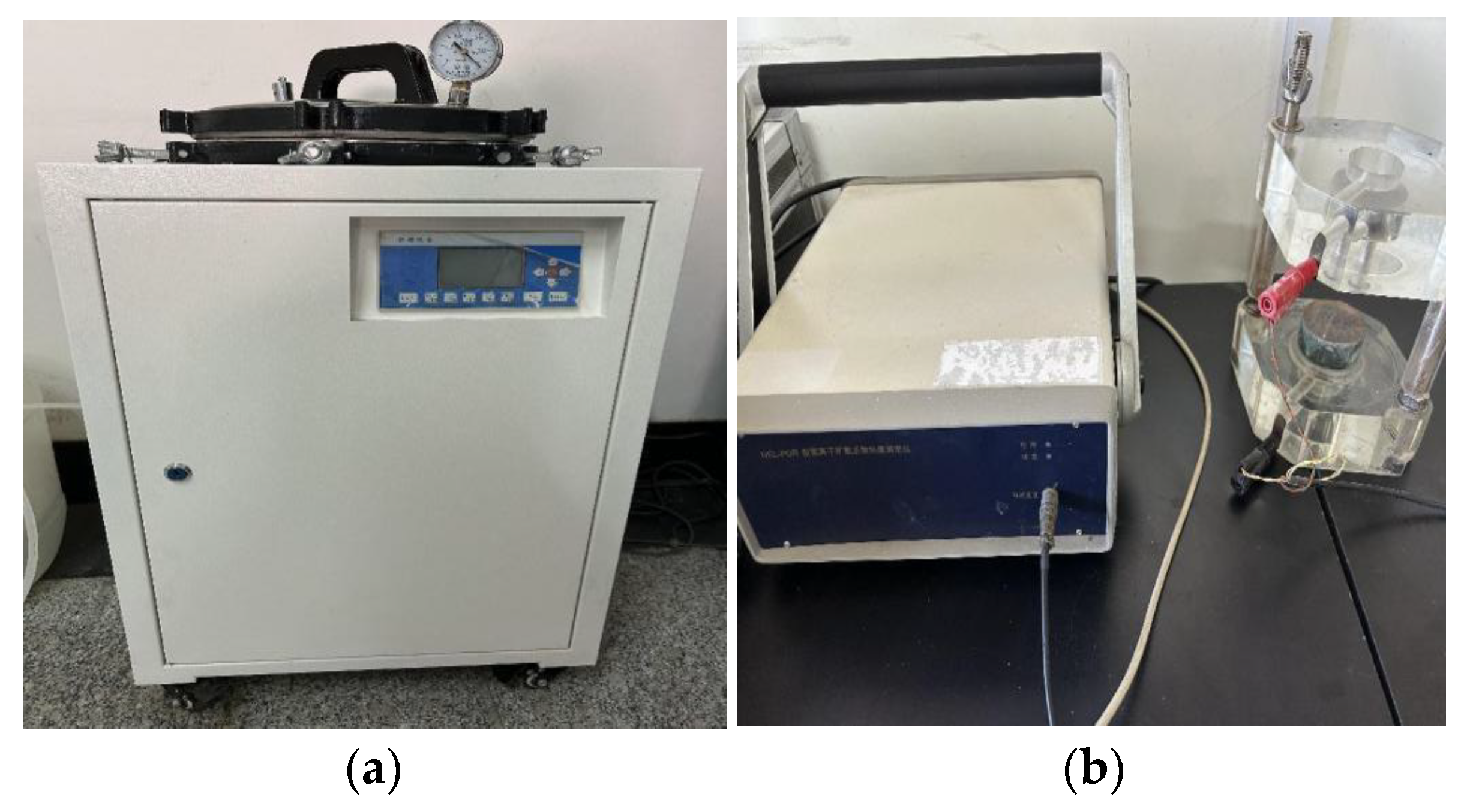
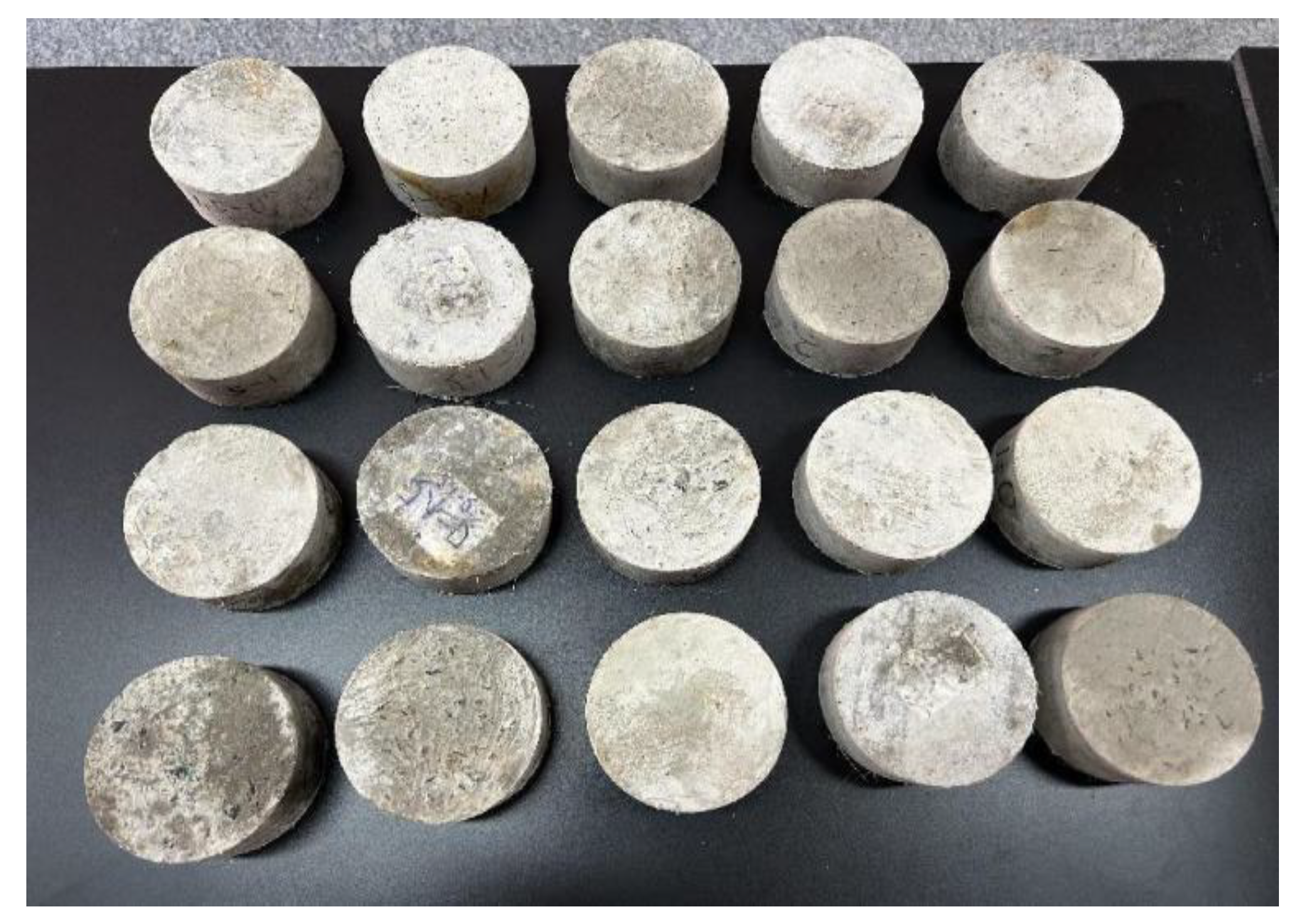
- According to the standard, 100 × 50 mm cylinder test blocks were made. The three test blocks were a group. After 28 days of curing, the vacuum-saturated salt treatment was carried out. The machine is shown in Figure 4a. The NEL-PDR chloride diffusion coefficient tester was used to test the chloride ion permeability of the test blocks, as shown in Figure 4b. The NEL-PDR chloride ion diffusion coefficient rapid tester is a concrete permeability tester developed using the chloride ion diffusion coefficient test principle proposed by Professor Lu. The device can quickly detect the chloride ion diffusion coefficient in concrete, to evaluate the permeability of concrete.
- (2)
- The test used the method proposed by Professor Lu [27] of Tsinghua University. The test principle was based on the Nernst–Einstein equation. The concrete is regarded as a solid electrolyte, and the diffusion coefficient of the charged particle i in the concrete is related to its partial conductance. On this basis, if the concentration Ci of the ion i and the partial conductance are known, it is easy to obtain the diffusion coefficient of the ion i. After vacuum-saturated salt treatment, there is only one ion in the specimen—Cl−. At this time, it can be assumed that the ion migration number of the specimen is 1 and the chloride ion concentration in the concrete pore solution is Ci. The formula is (4).where Di is the diffusion coefficient of charged particle i, s/m; is the partial conductivity of charged particles, s/m; R is the gas constant, equal to 8.314 J/mol·K; T is the absolute temperature—if it meets the laboratory standard temperature, the value is 298 K; Zi is the charge number of charged particles, i; f is the Faraday constant, taking 96,500 Coul/mol, and Ci is the number concentration of charged particles, cm3/mol.
2.2.3. Sulfate Corrosion Resistance Test
3. Analysis and Discussion of Results
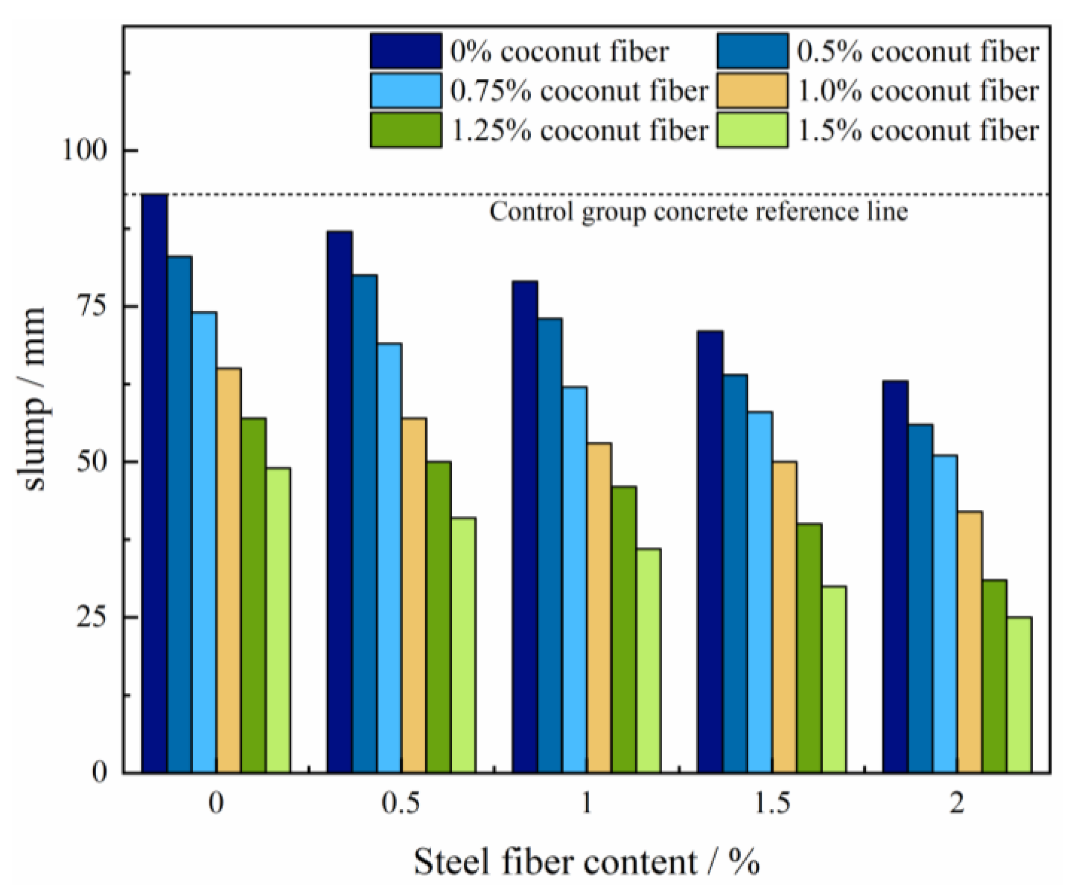
3.1. Slump Value
3.2. Mechanical Properties of Concrete
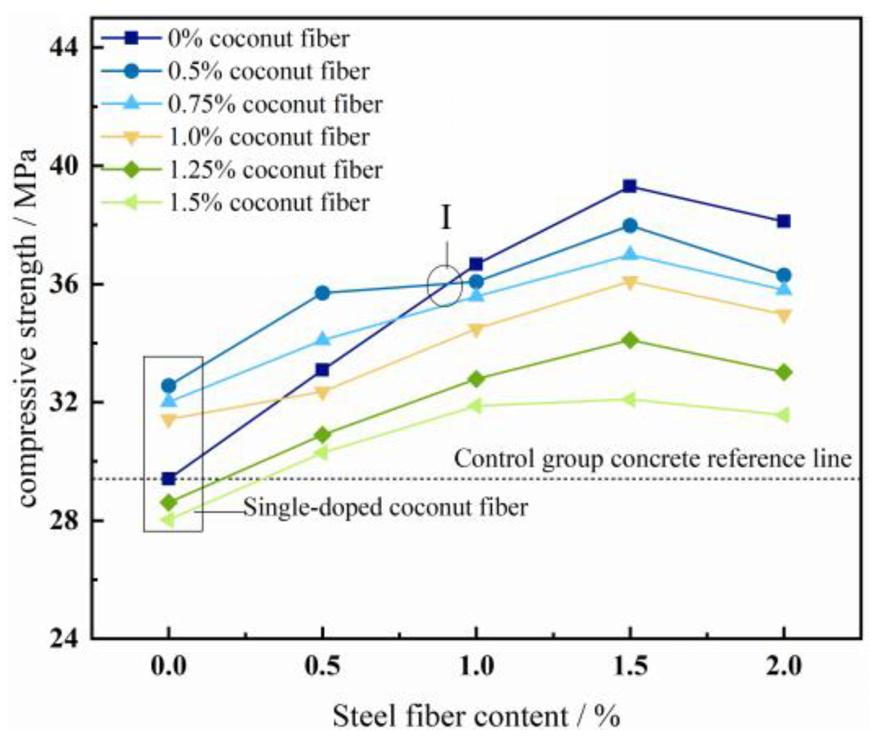
3.2.1. Compressive Strength
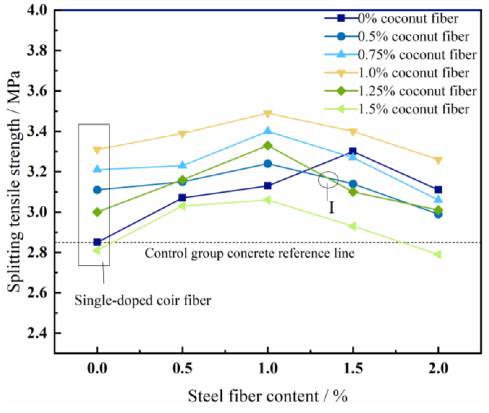
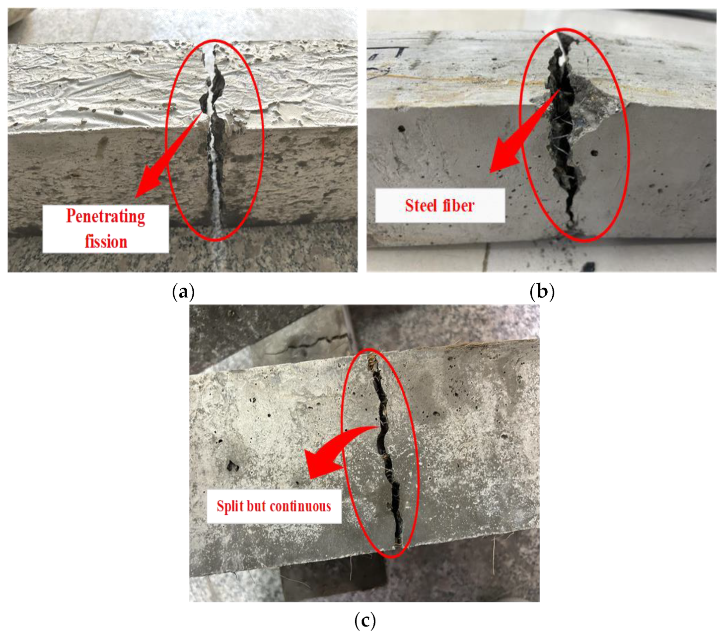
3.2.2. Splitting Tensile Strength
3.2.3. Flexural Strength
3.3. Concrete Durability Properties
3.3.1. Chloride Diffusion Coefficient
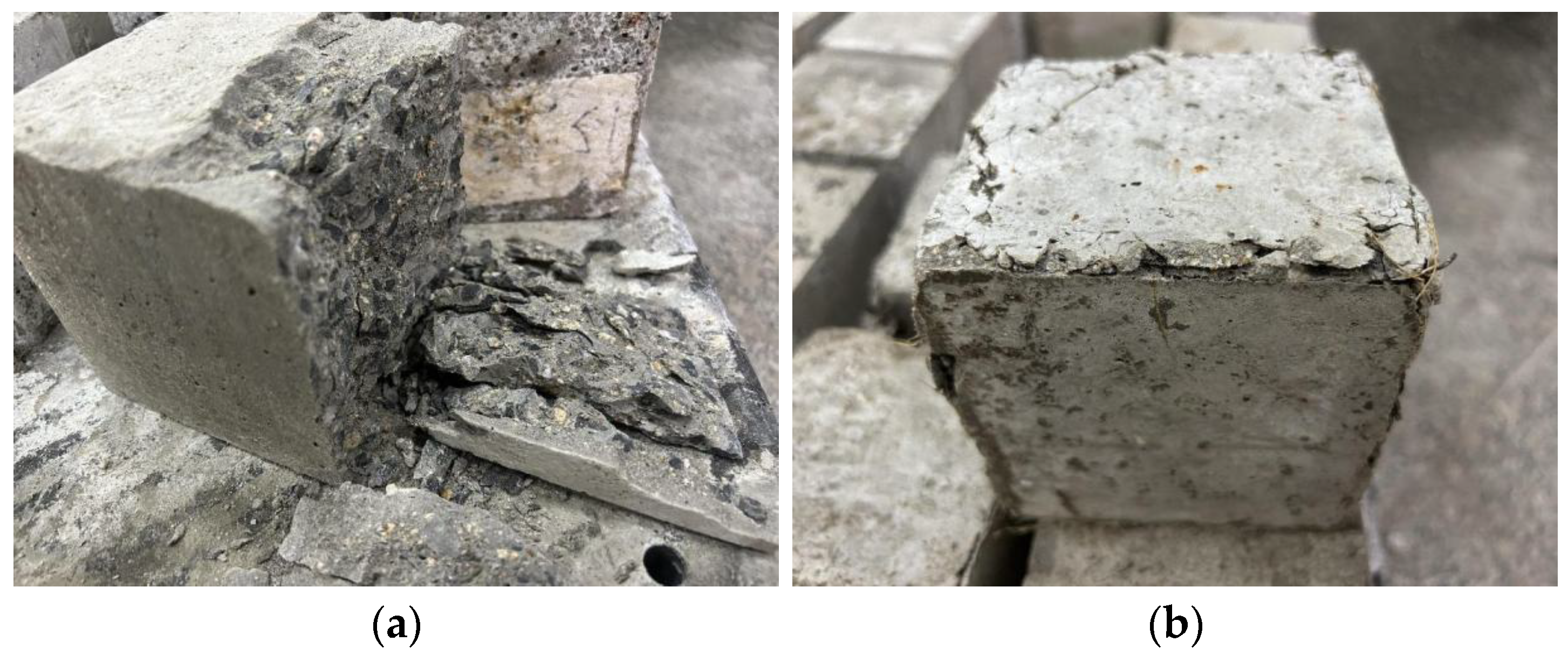
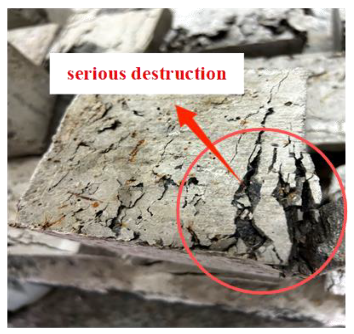
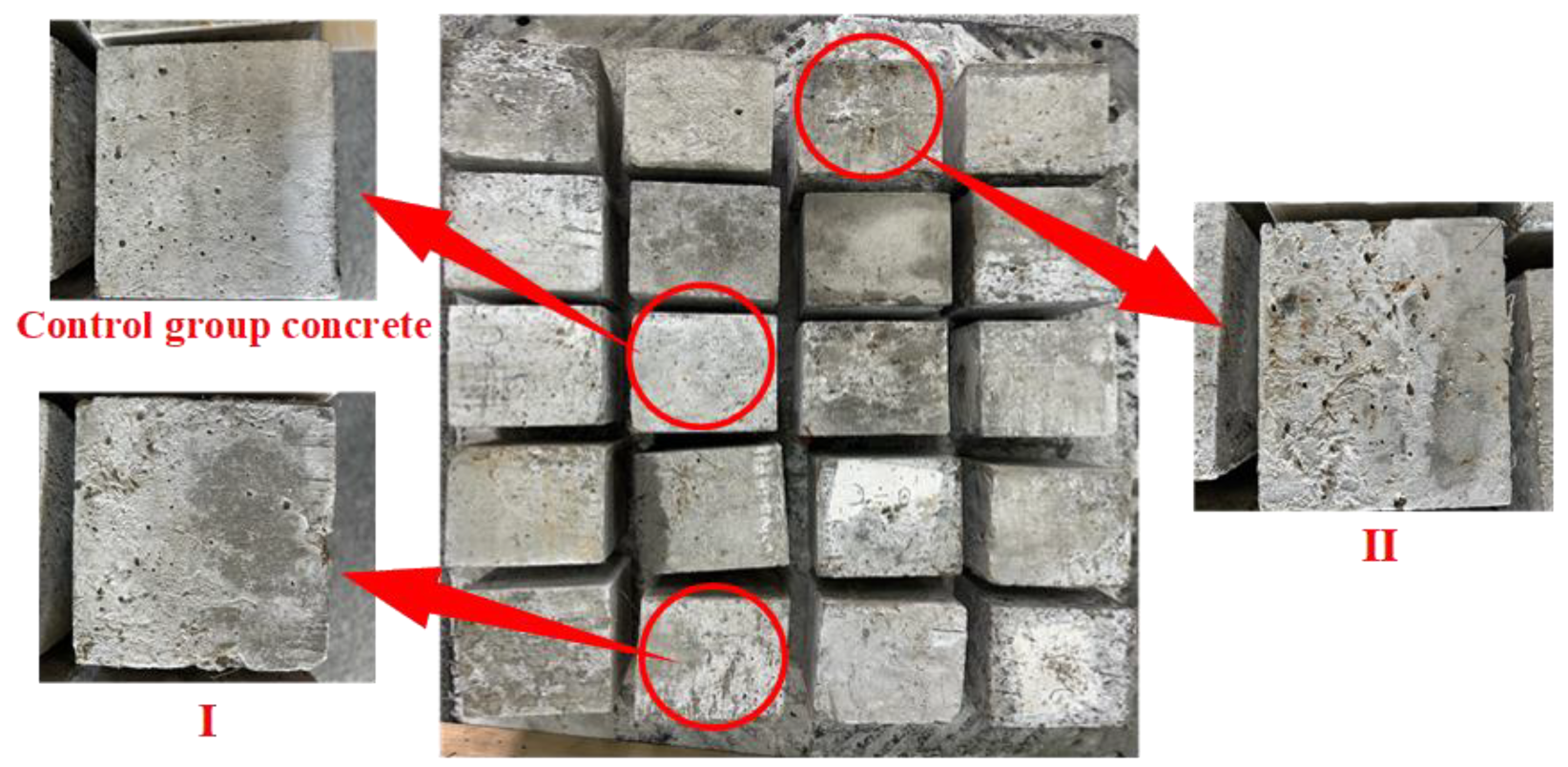
3.3.2. Resistance to Sulphate Corrosion
4. Conclusions
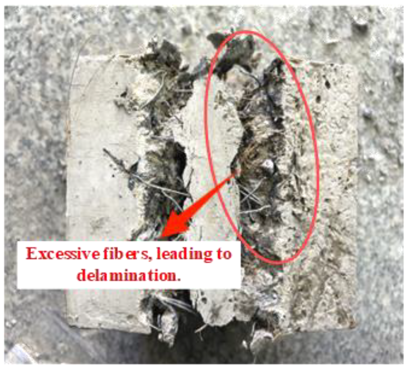
- With the admixture of fibers, the mechanical properties of fly ash concrete all showed a trend of first increasing and then decreasing, and the mixed fiber fly ash concrete had better performance compared to the steel fiber concrete and coir fiber concrete. The synergistic effect between the different fibers gave the concrete a better resistance to impact;
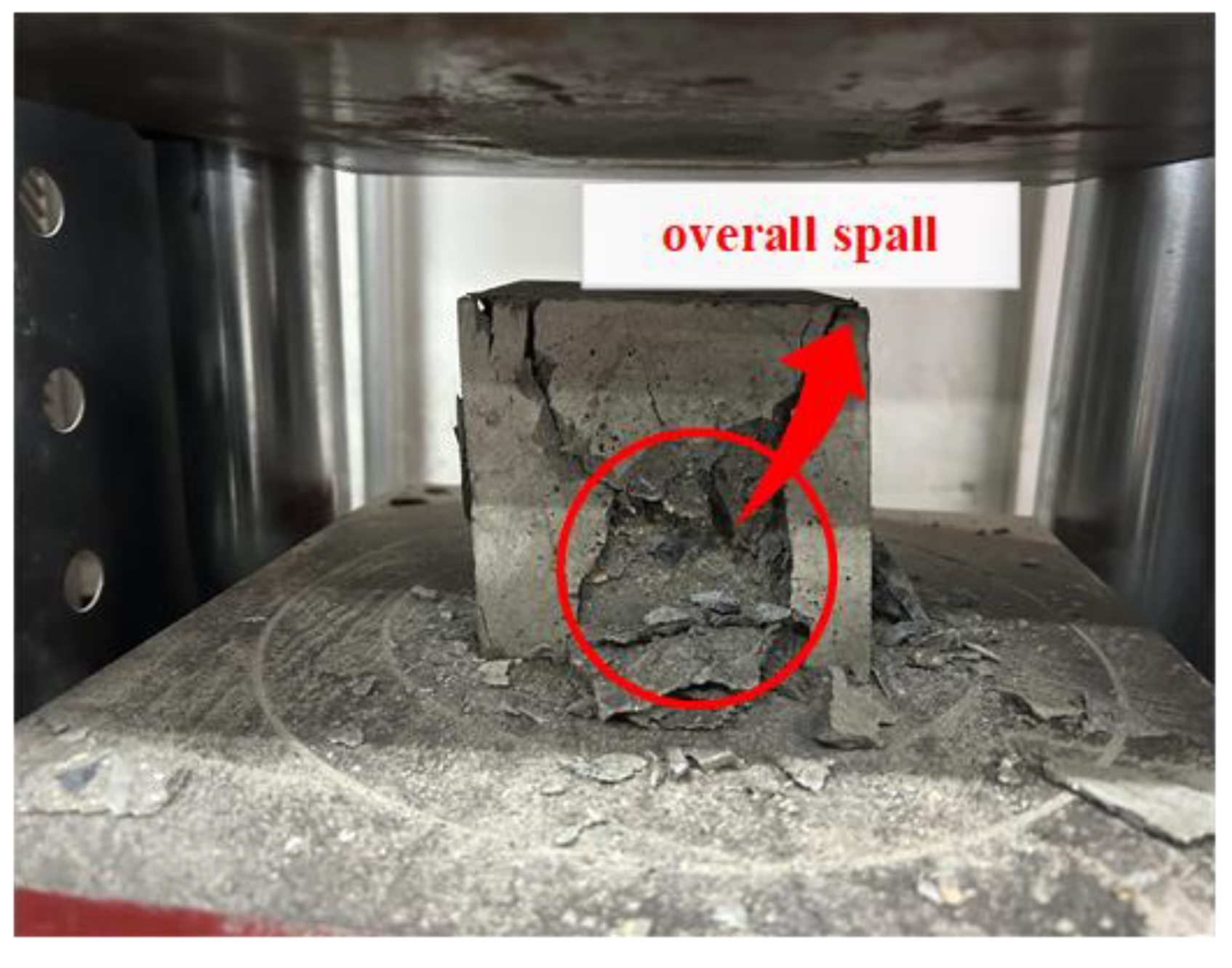
- The results of the mechanical properties tests showed that the inclusion of an appropriate amount of fibers can induce the fly ash concrete to change the brittle damage of the matrix into ductile damage at the time of destruction. When the volume admixture of both steel fibers and coconut fibers was 1.0%, the bridging effect of the fibers significantly enhanced the flexural strength of the fly ash concrete. The strength was enhanced by 26.58% compared to the control group;
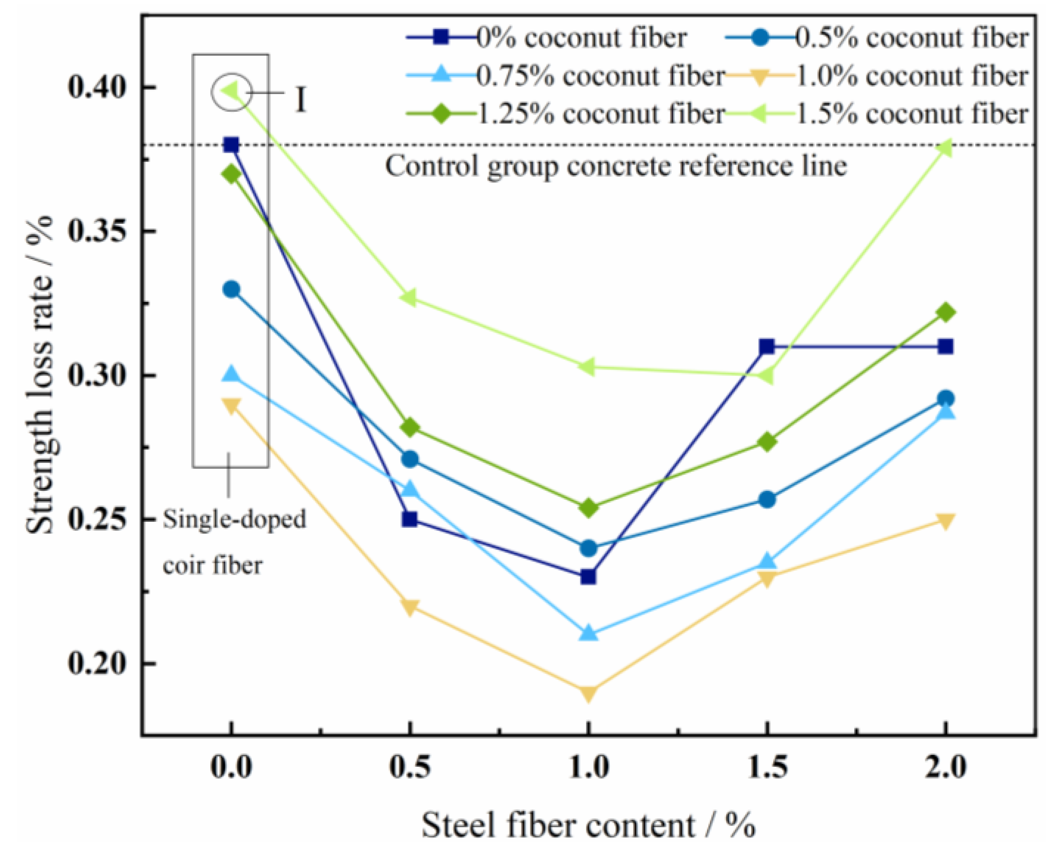
- The results of the durability tests showed that when steel fibers were mixed with coconut fibers at an equal volume ratio of 1.0%, they not only effectively reduced the diffusion of chloride ions, but also resisted the erosive effect of sulfates to the maximum extent. Using an appropriate amount of fibers can effectively inhibit the extension of concrete cracks, thus preventing the penetration and diffusion of aggressive substances;
- In this study, the key indexes of compressive strength, flexural strength, and resistance to sulphate corrosion in the mix were considered for the tunnel lining environment in coastal areas. The optimal ratio of hybrid fibers in the fly ash concrete used to enhance the comprehensive performance was found through the tests. The durability of the matrix was significantly enhanced while improving the toughness and crack resistance of the concrete. The composite application of steel fibers and coconut fibers can therefore effectively extend the service life of a tunnel lining structure and improve its sustainable utilization.
Author Contributions
Funding
Data Availability Statement
Acknowledgments
Conflicts of Interest
References
- Tiberti, G.; Minelli, F.; Plizzari, G. Reinforcement optimization of fiber reinforced concrete linings for conventional tunnels. Compos. Part B Eng. 2014, 58, 199–207. [Google Scholar] [CrossRef]
- Kaufmann, W.; Amin, A.; Beck, A.; Lee, M. Shear transfer across cracks in steel fibre reinforced concrete. Eng. Struct. 2019, 186, 508–524. [Google Scholar] [CrossRef]
- Kooiman, A.G. Modelling Steel Fibre Reinforced Concrete for Structural Design. 2000. Available online: http://resolver.tudelft.nl/uuid:e7a12191-4484-4fc3-b4c5-e8c0d51271a0 (accessed on 30 October 2000).
- Wu, Z.; Shi, C.; Khayat, K.H. Investigation of mechanical properties and shrinkage of ultra-high performance concrete: Influence of steel fiber content and shape. Compos. Part B Eng. 2019, 174, 107021. [Google Scholar] [CrossRef]
- Buratti, N.; Ferracuti, B.; Savoia, M. Concrete crack reduction in tunnel linings by steel fibre-reinforced concretes. Constr. Build. Mater. 2013, 44, 249–259. [Google Scholar] [CrossRef]
- Zhang, H.; Cao, L.; Duan, Y.; Tang, Z.; Hu, F.; Chen, Z. High-flowable and high-performance steel fiber reinforced concrete adapted by fly ash and silica fume. Case Stud. Constr. Mater. 2024, 20, e02796. [Google Scholar] [CrossRef]
- Wu, F.; Yu, Q.; Chen, X. Effects of steel fibre type and dosage on abrasion resistance of concrete against debris flow. Cem. Concr. Compos. 2022, 134, 104776. [Google Scholar] [CrossRef]
- Nehdi, M.L.; Abbas, S.; Soliman, A.M. Exploratory study of ultra-high performance fiber reinforced concrete tunnel lining segments with varying steel fiber lengths and dosages. Eng. Struct. 2015, 101, 733–742. [Google Scholar] [CrossRef]
- Chiaia, B.; Fantilli, A.P.; Vallini, P. Combining fiber-reinforced concrete with traditional reinforcement in tunnel linings. Eng. Struct. 2009, 31, 1600–1606. [Google Scholar] [CrossRef]
- Shao, G.D. Research on Mechanical Properties and Durability of Tunnel Prefabricated Lining Blocks. Mod. Urban Rail Transp. 2017, 11, 71–74. Available online: https://kns.cnki.net/kcms2/article/abstract?v=01ddXewXOSDZvClQIL1GDKvKj9vNQWup8JCAMK5m4qUP-Y5MK66lghcvPKOEhtf5H6q8UCULyvy3nAWCnspIEaRsNOiYhV8Fo9kMXhwupPUgwd2J7DVqFlWVLjRxVm63kvGuERIBx1BQ9OFlWWHAlWqeY_f6ZDVXYyitZWzAFJcpd9xcqgTEtjtD_Z7Z6fgOkZKR0i_yzUQ=&uniplatform=NZKPT&language=CHS (accessed on 20 November 2017). (In Chinese).
- You, S.; Ji, H.; Liu, J.; Song, C.; Tang, W. Fracture performance of macro synthetic steel fiber concrete exposed to a sulfate environment. Anti-Corros. Methods Mater. 2016, 63, 236–244. [Google Scholar] [CrossRef]
- Cui, G.-Y.; Qi, J.-S.; Wang, D.-Y. Experimental study on load bearing characteristics of steel fiber reinforced concrete lining in the soft surrounding rock tunnel. Adv. Civ. Eng. 2020, 2020, 4976238. [Google Scholar] [CrossRef]
- Liu, Y.; Shi, C.; Zhang, Z.; Li, N.; Shi, D. Mechanical and fracture properties of ultra-high performance geopolymer concrete: Effects of steel fiber and silica fume. Cem. Concr. Compos. 2020, 112, 103665. [Google Scholar] [CrossRef]
- Cui, G.-Y.; Wang, X.-L.; Wang, D.-Y. Study on the model test of the antibreaking effect of fiber reinforced concrete lining in tunnel. Shock Vib. 2020, 2020, 5419650. [Google Scholar] [CrossRef]
- Mwaikambo, L.Y.; Ansell, M.P. Mechanical properties of alkali treated plant fibres and their potential as reinforcement materials II. Sisal fibres. J. Mater. Sci. 2006, 41, 2497–2508. [Google Scholar] [CrossRef]
- Ali, M.; Liu, A.; Sou, H.; Chouw, N. Mechanical and dynamic properties of coconut fibre reinforced concrete. Constr. Build. Mater. 2012, 30, 814–825. [Google Scholar] [CrossRef]
- Hwang, C.-L.; Tran, V.-A.; Hong, J.-W.; Hsieh, Y.-C. Effects of short coconut fiber on the mechanical properties, plastic cracking behavior, and impact resistance of cementitious composites. Constr. Build. Mater. 2016, 127, 984–992. [Google Scholar] [CrossRef]
- Reis, J.M.L. Fracture and flexural characterization of natural fiber-reinforced polymer concrete. Constr. Build. Mater. 2006, 20, 673–678. [Google Scholar] [CrossRef]
- Wu, H.; Huang, M.; Zhang, L.; Xie, Z.; Zhang, J. Experimental study on compressive performance of coconut fiber MPC compositen cement-based materials. J. Xi’an Univ. Arch. Technol. (Nat. Sci. Ed.) 2022, 54, 257–266. Available online: https://link.cnki.net/doi/10.15986/j.1006-7930.2022.02.013 (accessed on 28 April 2022).
- Ahmad, W.; Farooq, S.H.; Usman, M.; Khan, M.; Ahmad, A.; Aslam, F.; Al Yousef, R.; Al Abduljabbar, H.; Sufian, M. Effect of coconut fiber length and content on properties of high strength concrete. Materials 2020, 13, 1075. [Google Scholar] [CrossRef]
- Ramli, M.; Kwan, W.H.; Abas, N.F. Strength and durability of coconut-fiber-reinforced concrete in aggressive environments. Constr. Build. Mater. 2013, 38, 554–566. [Google Scholar] [CrossRef]
- Ali, B.; Ahmed, H.; Kahla, N.B.; Amir, M.T.; Azab, M.; Raza, A. A critical review on the utilization of coconut (coconut fiber) in cementitious materials. Constr. Build. Mater. 2022, 351, 128957. [Google Scholar] [CrossRef]
- GB/T 39698-2020; Confirmation Methods for Delivering Common Portland Cement. State Market Regulatory Administration: Beijing, China, 2020. (In Chinese)
- JGJ 2006; Standard for Technical Requirements and Test Method of Sand and Crushed Stone for Ordinary Concrete. China Academy of Building Research: Beijing, China, 2006. (In Chinese)
- GB/T 50081-2019; Standard for Test Method of Mechanical and Physical Performance Concrete. China Architecture and Building Press: Beijing, China, 2019. (In Chinese)
- GB/T 50082-2009; Standard for Test Methods of Long-Term Performance and Durability of Ordinary Concrete. Ministry of Housing and Urban-Rural Development of the People’s Republic of China: Beijing, China, 2009. (In Chinese)
- Lu, X. Application of the Nernst-Einstein equation to concrete. Cem. Concr. Res. 1997, 27, 293–302. [Google Scholar] [CrossRef]
- Rudraswamy, M.; Patagundi, B.; Prakash, K. The Workability Studies of Hybrid Fiber Reinforced Concrete Formed by Using Fibs of Different Aspect Ratio. Int. J. Civ. Eng. Technol. 2018, 9, 1293–1301. Available online: http://iaeme.com/Home/issue/IJCIET?Volume=9&Issue=7 (accessed on 21 July 2018).
- Hasan, M.; Saidi, T.; Jamil, M.; Amalia, Z.; Mubarak, A. Mechanical properties and absorption of high-strength fiber-reinforced concrete (HSFRC) with sustainable natural fibers. Buildings 2022, 12, 2262. [Google Scholar] [CrossRef]
- Hasan, M.; Saidi, T.; Mubarak, A.; Jamil, M. Effect of calcined diatomaceous earth, polypropylene fiber, and glass fiber on the mechanical properties of ultra-high-performance fiber-reinforced concrete. J. Mech. Behav. Mater. 2023, 32, 20220275. [Google Scholar] [CrossRef]
- Song, P.S.; Hwang, S. Mechanical properties of high-strength steel fiber-reinforced concrete. Constr. Build. Mater. 2004, 18, 669–673. [Google Scholar] [CrossRef]
- Caggiano, A.; Folino, P.; Lima, C.; Martinelli, E.; Pepe, M. On the mechanical response of hybrid fiber reinforced concrete with recycled and industrial steel fibers. Constr. Build. Mater. 2017, 147, 286–295. [Google Scholar] [CrossRef]
- Raj, B.; Sathyan, D.; Madhavan, M.K.; Raj, A. Mechanical and durability properties of hybrid fiber reinforced foam concrete. Constr. Build. Mater. 2020, 245, 118373. [Google Scholar] [CrossRef]
- Xie, Y.; Sheng, M.; Lv, Y. Experimental Study on Mechanical Properties of Steel Fiber Concrete. Sichuan Cem. 2020, 7, 14–15. Available online: https://kns.cnki.net/kcms2/article/abstract?v=01ddXewXOSBUDlO_Ri52Yj0I8xGpGKqf8g5aOetO0NiUrMKNc-wlyIYOCcpj6o8oEeII1Z9C45X0ZkJh0BRtLMgKMIjGBW6ADxV0B5c9UzHRe08QJ1jkXRCJV_ahKgKY3uF6X0a6uI5-MkfPbj7U-IS-FsNA9stBrFDNC-KbI3ZzAWw3L3JuGFmo8bDFPPAWhjo1biUG5qU=&uniplatform=NZKPT&language=CHS (accessed on 15 July 2020). (In Chinese).
- Sivakumar, A.; Santhanam, M. Mechanical properties of high strength concrete reinforced with metallic and non-metallic fibres. Cem. Concr. Compos. 2007, 29, 603–608. [Google Scholar] [CrossRef]
- Das, S.; Sobuz, H.R.; Tam, V.W.Y.; Akid, A.S.M.; Sutan, N.M.; Rahman, F.M.M. Effects of incorporating hybrid fibres on rheological and mechanical properties of fibre reinforced concrete. Constr. Build. Mater. 2020, 262, 120561. [Google Scholar] [CrossRef]
- Bai, M.; Niu, D.; Jiang, G.; Wu, X. Study on the influence of steel fiber content on chloride ion permeability of concrete. China Concr. Cem. Prod. 2015, 11, 49–52. Available online: https://link.cnki.net/doi/10.19761/j.1000-4637.2015.11.012 (accessed on 20 November 2015).
- Paul, S.C.; Van Zijl, G.P.A.G.; Šavija, B. Effect of fibers on durability of concrete: A practical review. Materials 2020, 13, 4562. [Google Scholar] [CrossRef] [PubMed]


| Fiber Class | Length (mm) | Diameter (mm) | Density(g/cm3) |
|---|---|---|---|
| Steel fiber | 40 | 4 | 7.90 |
| Coconut fiber | 40-50 | 0.4 | 1.12 |
| Water to Cement Ratio | Water | Binding Material | Fine Aggregate | Coarse Aggregate | Admixture |
|---|---|---|---|---|---|
| kg/m3 | |||||
| 0.5 | 195 | 390 | 672.2 | 1142.8 | 1.95 |
Disclaimer/Publisher’s Note: The statements, opinions and data contained in all publications are solely those of the individual author(s) and contributor(s) and not of MDPI and/or the editor(s). MDPI and/or the editor(s) disclaim responsibility for any injury to people or property resulting from any ideas, methods, instructions or products referred to in the content. |
© 2024 by the authors. Licensee MDPI, Basel, Switzerland. This article is an open access article distributed under the terms and conditions of the Creative Commons Attribution (CC BY) license (https://creativecommons.org/licenses/by/4.0/).
Share and Cite
Dong, S.; Liu, W.; Li, H. Study on the Mechanical Properties and Durability of Tunnel Lining Concrete in Coastal Areas. Buildings 2024, 14, 2606. https://doi.org/10.3390/buildings14092606
Dong S, Liu W, Li H. Study on the Mechanical Properties and Durability of Tunnel Lining Concrete in Coastal Areas. Buildings. 2024; 14(9):2606. https://doi.org/10.3390/buildings14092606
Chicago/Turabian StyleDong, Sihui, Wei Liu, and Hongyi Li. 2024. "Study on the Mechanical Properties and Durability of Tunnel Lining Concrete in Coastal Areas" Buildings 14, no. 9: 2606. https://doi.org/10.3390/buildings14092606