Article

Numerical Investigation of the Influence of Foundation Pit Excavation on the Deformation of Underlying Tunnels Based on a Multi-Factor Orthogonal Test

1
China Construction Seventh Engineering Division Corp., Ltd., Zhengzhou 450004, China
2
College of Civil Engineering, Henan University of Technology, Zhengzhou 450001, China
3
China Railway 16th Bureau Group, Corp., Ltd., Beijing 100018, China
*
Author to whom correspondence should be addressed.
Buildings 2024, 14(9), 2618; https://doi.org/10.3390/buildings14092618
Submission received: 3 July 2024 / Revised: 18 August 2024 / Accepted: 22 August 2024 / Published: 24 August 2024
(This article belongs to the Section Building Structures)

Abstract

:
The excavation of pits will induce the vertical displacement of tunnels and lead to engineering problems. The shape as well as size of a pit, and the complex spatial position relationship between the pit and tunnel will induce different deformation responses of tunnel structures; however, the degree to which each factor influences tunnel structure deformation is still unclear. This paper studied the impact of excavation on the deformation of tunnels via a combination of numerical simulation and orthogonal tests. The deformation of tunnels induced by excavation was studied using a numerical method, after which the sensitivity of influencing factors to tunnel deformation was studied by means of range and variance analyses through a four-factor and three-level orthogonal test. The results show that, for a foundation pit with a long side perpendicular to the tunnel longitude, the excavation has the least influence on tunnel deformation. Tunnel deformation increased with an increase in the excavation depth and decreased with an increase in tunnel–pit vertical and horizontal distance. As the plane shape of the foundation pit is 20 m × 45 m, the depth of excavation is 4 m, the pit tunnel vertical distance is 13 m, and the pit tunnel horizontal distance is 28 m, the tunnel has the least deformation. Based on the results of this study, the position relationship between the pit and the tunnel can be optimized in terms of design and construction, and the aim of controlling tunnel deformation can be achieved.

1. Introduction

With the large-scale construction of underground structures in city regions, engineering activities around existing subway tunnels are becoming more and more frequent. For example, the Hangzhou railway metro station foundation pit and the Shenzhen Metro Gongmiao traffic hub west wind tunnel foundation pit are constructed above the subway tunnels [1,2]. The excavation construction of foundation pits on existing tunnels will induce the unloading of soil above tunnels and will change the displacement and stress fields around the existing tunnels. When tunnel deformation exceeds the threshold value, it will cause water leakage at tunnel joints, and lead subway tunnels to failure [3,4].
The problem of excavation construction of pits on underground tunnels has been investigated through theoretical, numerical, and experimental test methods. In theoretical research, Zhang raised semi-analytical means to determine tunnel floating displacement near foundation pits based on Mindlin’s and Boussinesq’s solutions, considering the rheological characteristics of soil, and studied the influence of foundation pit area, the position relation of tunnel foundation pit, and construction processes on tunnel displacement [5]. Zhang analyzed the impact of pit excavation construction on tunnel deformation through the stress unloading theory and Galerkin’s method [6]. Qiu simplified the excavation problem as Timoshenko beams on Winkler foundations, considering the shear effect of tunnels, and analyzed the effect of subgrade parameters, the distance between tunnels and pits, and soil stiffness on tunnel deformation [7]. Liang et al. simplified the problem to Euler–Bernoulli beams on Pasternak foundations, considering the effect of overburden pressure on tunnels and the dewatering process, and obtained the spacing effect of tunnel deformation [8,9,10,11]. Liu simplified tunnels as Timoshenko beams in Vlazov foundations and analyzed tunnel displacement through Mindlin’s theory [12]. Yang et al. considered the interaction of soil and structure, based on Mindlin’s and Boussinesq’s solutions, and analyzed the deformation of tunnels in rock and undulating strata of soil and rock [13,14]. Zhang considered the displacement of enclosure walls and studied the impact of additional stress in soil and deformation on tunnels [15].
In numerical simulations, Li et al. conducted a study on the displacement responses of tunnels under staged excavations, as well as unloading and reloading activity, through the finite element method [16,17]. Zhuang et al. conducted numerical parameter studies to investigate the effect of pit size, pit tunnel distance, and soil reinforcement measures on the deformation of tunnels, indicating that the influence scope of excavations on tunnels is around 6.0 times the width of foundation pits and that the settlement deformation and malformation of tunnel structures are induced by pit above tunnels, while horizontal deformation is caused by lateral excavation [18,19,20,21,22,23]. Tanoli et al. used a small stain model to model soil [24,25,26], while Shi used a hypoplastic model to model soil, and determined that tunnel displacement and strain are dull to tunnel joint stiffness [27]. Wang studied the effect of soil fabric on the lateral deformation of enclosure walls, surface sink, and tunnel displacement during the construction of adjoining pits [28]. Through a large number of numerical results, Zhang proposed an empirical equation between tunnel displacement and influence factors [29]. Liu et al. divided the influence scope of excavations on adjacent tunnels into three to four levels [30,31]. Zhao et al. proposed treatment measures, including shaft excavation with frictional pile slabs, isolation piles, the divided alternate excavation method, and zoned excavation with partition walls, to control the induced tunnel displacement [32,33,34,35]. Ye performed an optimized design study of foundation pit excavations based on numerical results to minimize tunnel displacement [36].
In a field test and laboratory test, Sharma et al. established the relation between structure deflection and unloading rate in addition to the relation between structure deformation and lateral contraction deformation, based on field test results [37,38,39,40,41]. Ran studied the dynamic prediction method of tunnel displacement based on a backpropagation neural network [42]. Li studied the responses of tunnels under multiple directional excavations [43]. Through an automatic monitoring method, Zhao proposed an automatic system with which to control groundwater level and strut axial force [44]. Zhu used the Brillouin optical frequency domain analysis method to study the strain on tunnels induced by excavation [45]. Ng et al. investigated the floating deflection of structures resulting from excavation through an indoor test and centrifuge test [46,47,48]. Liang et al. proposed the techniques of zoned excavation, cross walls, jet grouting, and real-time capsule grouting to reduce the structure displacement caused by excavation [49,50,51,52,53].
Although there have been many investigations on structure deformation due to excavation, the effect of the construction of pits on the deformation of existing structures is a complex three-dimensional problem, and existing research mostly utilized two-dimensional numerical models, which oversimplified the problem. Meanwhile, existing studies mainly focused on the cross-section deformation of tunnels, but research on tunnel longitudinal deformation is rather scarce. The displacement of underlying structures induced by the construction of pits is affected by many factors; however, the degree of influence of each factor is still unclear, and the analysis of the sensitivity of various influencing factors to the deformation of underlying tunnels is still insufficient.
In the study, a 3-dimensional finite element numerical method, considering the interaction of tunnels and excavations, was developed to study the impact of excavation on the displacement of underlying structures. The effect of single factors, including the plane shape of the foundation pit, excavation depth, and pit–tunnel distance on the uplift displacement of the underlying structure, is analyzed. Based on the outcome of a single-factor analysis, the peak settlement of underlying structures resulting from pit excavations is taken as the index, and the sensitivity degree of influencing factors was studied by range and variance analyses via the combination of numerical simulation and orthogonal tests. Through the outcomes of this research, the factors that have a significant impact on the tunnel response can be determined; considering the engineering environment and the smallest impact on tunnels, the optimal design method of the pit can be determined. The outcomes offer a reference for the protection of existing tunnels under deep excavation conditions.

2. Numerical and Orthogonal Test Methods

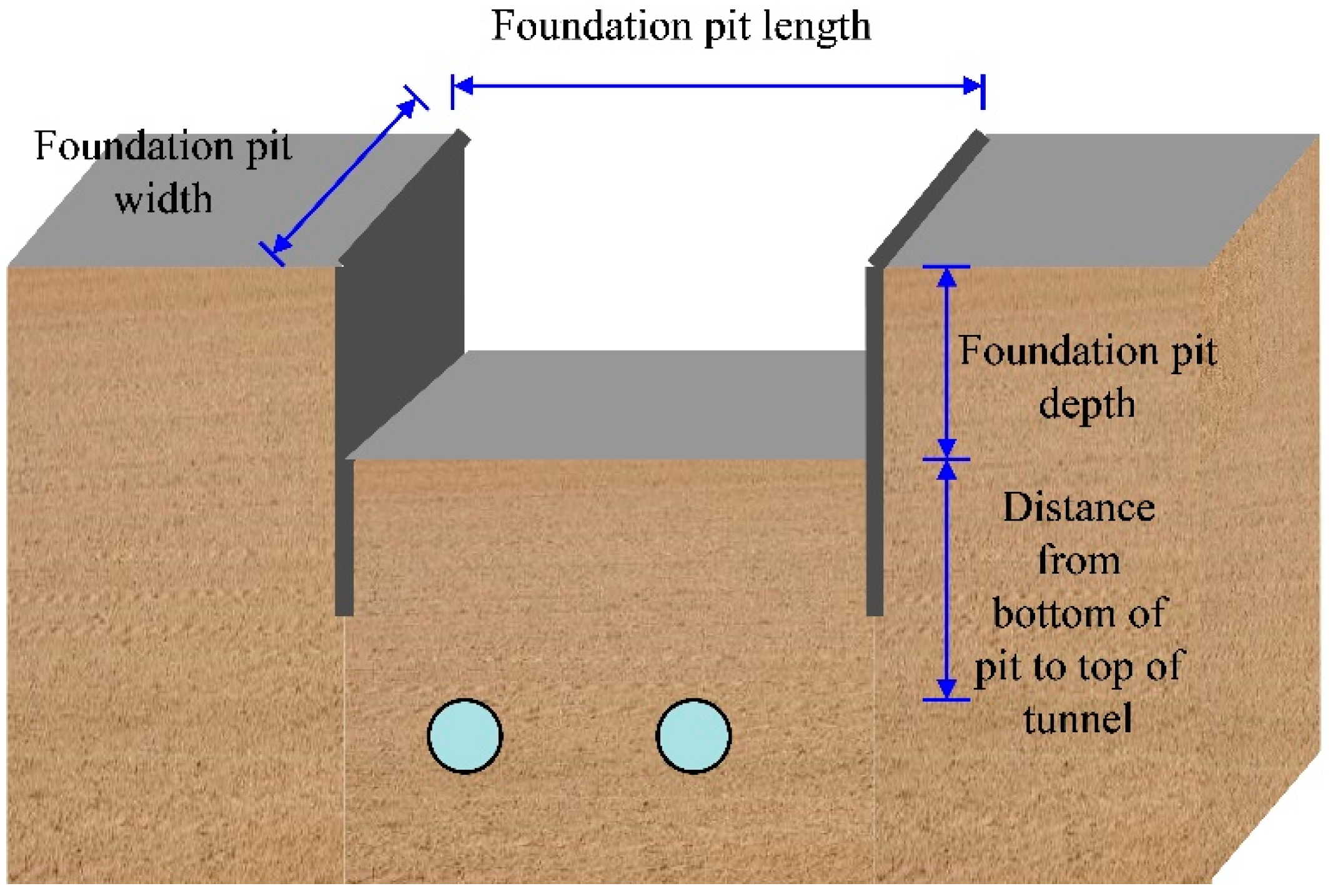
2.1. Overview of the Project

The Zhengzhou Subway No. 1 tunnel is studied, which is located beneath a deep foundation pit. The pit has a depth of 8 m, pit length parallel to the axis of tunnel is 20 m, and the width of pit is 45 m.
The supporting system of pit has the form of an underground retaining wall combined with steel support. The retaining wall is 1 m thick, and 16 m high. Three rows of steel supports are located 1 m, 3 m, and 5 m below the Earth’s surface, and the horizontal space of steel supports is 5 m. The tunnel center is 20 m below Earth’s surface, and the two tunnels are 13 m between each other. The line of the two tunnels parallels the foundation pit line. The positions of the tunnel and pit are shown in Figure 1.

2.2. Numerical Model

In this study, the numerical investigation was performed by ABAQUS software version 2019 on a Lenovo Thinkstation C30 workstation. The influence range induced by pit is approximately 3~4 times of cutting depth in plane; the influence depth is approximately 2~2.5 times of cutting depth below foundation pit bottom. Hence, the dimensions of a 3D finite element numerical model are selected as 120 m × 120 m × 40 m. In the numerical model, a C3D8R solid cell was applied to simulate the soil, lining, and underground retaining structure and a beam unit was used to model the support. Lateral limiting restrictions were applied on the 4 lateral faces of the model, and a fixed displacement restriction was imposed on the base of the model.
The parameters of foundation soil were obtained on the basis of a geological exploration of the project site. The prime soil in the project area is miscellaneous soil, silt, silt clay, and fine sand, which are typical soil layers in Zhengzhou [54]. The subsoil was modeled by a Mohr–Coulomb elastoplastic model and the subsoil parameters are shown in Table 1. Concrete structures, including an underground retaining wall and tunnel lining, are modeled as linear elastic material; the elastic modulus of the concrete is 34.5 GPa, and the Poisson’s ratio is 0.2. The elastic modulus of the steel support is 206 GPa, and the Poisson’s ratio is 0.3. The contact between the underground structure and soil is modeled based on contact mechanics, the structure and soil have a finite slip contact, and the coefficient of friction is 0.35.
The calculation procedure is as described below: (1) balance geo-stress to obtain a foundation with equilibrium soil stress, (2) excavate the soil in the tunnel position, and construct the lining, (3) construct the continuous wall, (4) excavate the soil in the pit, and erect the support layer-by-layer until the bottom is reached. The modulus softening method [55,56] is adopted to simulate the excavation and support process, i.e., the soil modulus is reduced before excavation, after which soil is removed after the support structure is applied. The proposed numerical model is shown in Figure 2.

2.3. Contrastive Analysis of the Numerical Method and Theoretical Method

The contour of the vertical deformation of the underground subway after excavation construction is illustrated in Figure 3. As is illustrated in the figure, both the two tunnels moved upward under the cutting conditions, and the vertical displacements on the two tunnels are close to each other. The vertical displacement outcomes on the tunnel drawn from the numerical means were compared with the results of a two-stage analysis method [7], as illustrated in Figure 4. As can be analyzed according to the outcomes, the peak vertical deformation on the tunnel was situated in the center of the foundation pit, while far from the excavation center the tunnel vertical displacement gradually decreased. The peak floating deformation of the tunnel determined by the numerical method was 10.4 mm, and the result obtained by the two-stage method was 13.5 mm. The numerical calculation outcomes are close to the theoretical outcomes, and the numerical model has good reliability.

2.4. Orthogonal Test Method

Orthogonal experiments have great advantages in the study of multi-factor and multi-level problems. Based on the orthogonal test method, this study takes the peak floating deformation on the tunnel as the index and studies the impact of excavation factors on the displacement of existing underlying tunnels. According to the analysis of a single-factor numerical calculation, four test factors, including the foundation pit plane shape, B × L, excavation depth, d, pit tunnel vertical distance, hv, and pit tunnel horizontal distance, he, were selected in the orthogonal test study. The upper, lower, and middle values are taken as the three levels. The form of the pit is 20 m × 45 m, 30 m × 30 m, and 45 m × 20 m; the pit depth is 4 m, 8 m, and 12 m; the pit tunnel vertical distance is 5 m, 9 m, and 13 m; and the pit tunnel horizontal distance is 0 m, 14 m, and 28 m; therefore, numerical orthogonal experiments were conducted with 4 factors and 3 levels. Based on the orthogonal design method, a total of 81 numerical models are reduced to 9. The orthogonal table, L9 (34), is illustrated in the Table 2.

3. Results and Discussion

3.1. Single-Factor Analysis

The proposed finite element numerical model was used to investigate the effect of the excavation construction of a pit on the displacement of existing tunnels under four single factors: the plane form of a pit, the foundation pit depth, the tunnel pit vertical distance, and the pit tunnel horizontal distance. In the following analysis, only a single-line tunnel is studied.
(1)
Effect of the Plane Shape of a Pit
In the study, the pit area was 900 m2, and the plane shape (width × length, B × L) was 20 m × 45 m, 30 m × 30 m, and 45 m × 20 m. The vertical displacement results on a tunnel are illustrated in Figure 5. It can be analyzed through the result that, after the excavation of the pit, the tunnel moved upward; the plane shape of a pit has a significant influence on the tunnel’s vertical displacement. When B × L is 30 m × 30 m, the maximum floating displacement induced by the excavation of a foundation pit is 13.04 mm. When B × L is 45 m × 20 m, i.e., the long side of the pit is parallel to the tunnel, the maximum vertical deformation of the tunnel decreased to 11.53 mm. When B × L is 20 m × 45 m, i.e., the long side of the pit is perpendicular to the tunnel, the peak vertical deformation on the tunnel has the lowest value of 10.4 mm, and the result is reduced by about 20.2% compared with that for the square pit. Therefore, when a pit has the same area, the tunnel has the lowest displacement as the tunnel is perpendicular to the long side of a pit, and the influence on the tunnel is also the smallest.
(2)
Effect of the Pit Depth
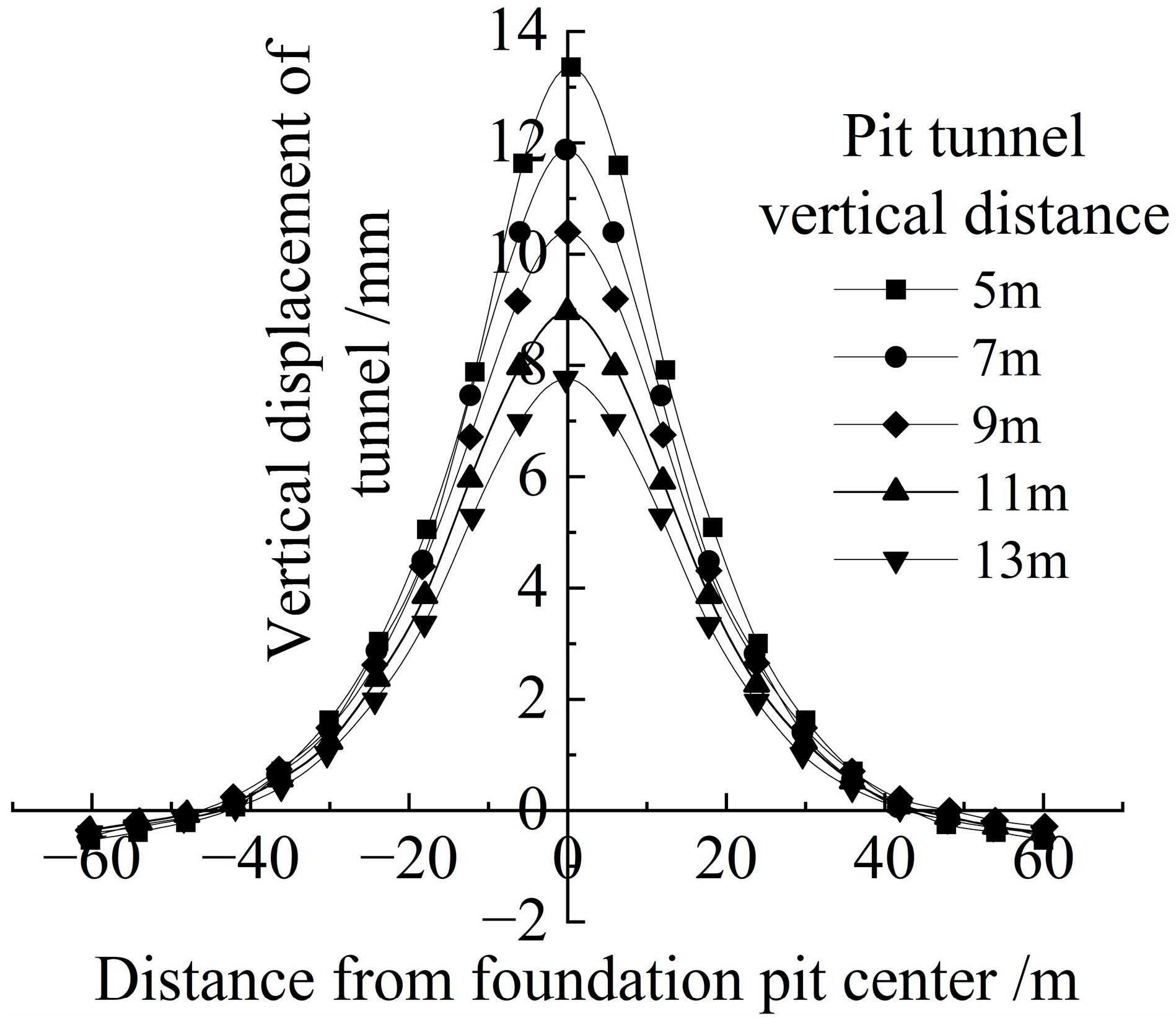
Under the same pit size and pit tunnel distance, the vertical displacement on a tunnel under pit excavation depths of 4 m, 6 m, 8 m, 10 m, and 12 m is illustrated in Figure 6. As can be observed from the results, the maximum vertical displacements on the tunnel are 4.6 mm, 7.3 mm, 10.4 mm, 13.9 mm, and 17.8 mm when the depths of excavations are 4 m, 6 m, 8 m, 10 m, and 12 m, respectively. The maximum vertical displacement on an underlying tunnel increased with an increase in the depth. The depth of the pit increased from 4 m to 12 m; the peak value of the vertical displacement on the tunnel increased by about 3.9 times.
As the cutting construction depth raised, the reduction in the soil stress on the tunnel increased, resulting in larger additional vertical deformation and stress on the tunnel. When the excavation depth is larger than 8 m, the peak tunnel deformation is close to the warning value of the Chinese standard [57].
(3)
Effect of Tunnel–Pit Vertical Distance
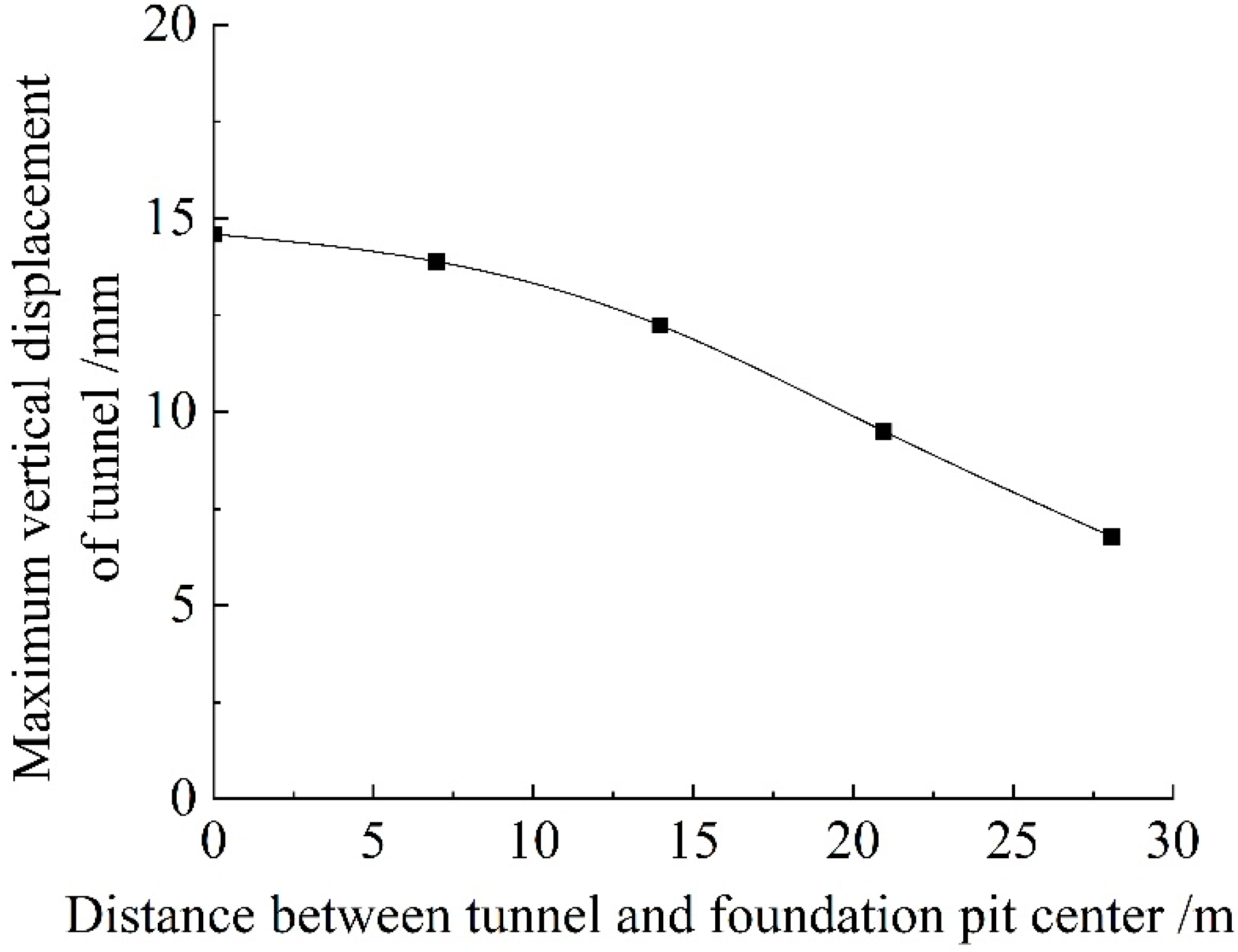
Under the same pit size, excavation depth, and pit tunnel horizontal distance, the floating deformation on the tunnel under pit tunnel vertical distances of 5 m, 7 m, 9 m, 11 m, and 13 m is shown in Figure 7. As can be concluded from the result, when pit tunnel vertical distances are 5 m, 7 m, 9 m, 11 m, and 13 m, the peak floating deformation on the tunnel is 13.4 mm, 11.9 mm, 10.4 mm, 9 mm, and 7.6 mm, respectively, indicating that, as the pit tunnel vertical distance grew from 5 m to 13 m, the tunnel vertical deformation decreased by 42.2%.
The disturbance to the soil near the pit is large, while the disturbance to soil far away from the foundation pit is small. The construction of a pit has a disturbance range to the adjacent soil. The strong influence zone is located within the range of less than 9 m, about 1.5 times the tunnel diameter.
(4)
Effect of Tunnel–Pit Horizontal Distance
Under the same pit size, excavation depth, and pit tunnel vertical distance, the peak value of the vertical deformation on the tunnel under pit tunnel horizontal distances of 0 m, 7 m, 14 m, 21 m, and 28 m is illustrated in Figure 8. As can be observed from the outcomes, for pit tunnel horizontal distances of 0 m, 7 m, 14 m, 21 m, and 28 m, the maximum vertical displacements on the tunnel are 14.6 mm, 13.9 mm, 12.2 mm, 9.5 mm, and 6.8 mm, respectively. This indicates that, with a rise in the pit tunnel’s horizontal distance, the floating displacement of the tunnel decreased. When the horizontal distance between the pit and the tunnel is larger than 14 m, the vertical displacement of the tunnel decreases significantly. The pit tunnel horizontal distance raised from 0 m to 28 m, and the peak vertical displacement decreased by 7.8 mm or about 53.6%.

3.2. Orthogonal Test Results

The peak floating deformation of the existing underlying tunnel raised from foundation pit excavation is obtained by the nine numerical models in single-factor analysis. Based on the orthogonal test scheme listed in Table 2, the sensitivity of each factor to the underlying tunnel is analyzed by the maximum vertical displacement value on the tunnel; the outcomes are illustrated in Table 3.
The range analysis of factors’ impact on the peak floating deformation of the underlying tunnel is shown in Table 4, where K1, K2, and K3 are the statistical parameters of each factor under three levels and R is the amplitude of the variation in the maximum vertical displacement on the tunnel. The range analysis results indicate that the factors according to the degree to which they influence the peak floating deformation of the tunnel, from large to small, are the excavation depth, pit tunnel horizontal distance, pit tunnel vertical distance, and pit shape. The minimum combination of tunnel maximum vertical displacement is A1B1C3D3; i.e., the pit shape is 20 m × 45 m, the cutting depth is 4 m, the pit tunnel vertical distance is 13 m, and the pit tunnel horizontal distance is 28 m, and the tunnel has the least deformation.
The variance analysis of factors’ influence on the tunnel’s maximum vertical displacement is illustrated in Table 5, where Q is the degree of dispersion of the test data, f is the degrees of freedom, and F is the degrees to which factors influence the peak floating displacement on the tunnel. The results indicate that the cutting depth of a pit has the most significant influence on the tunnel’s vertical displacement, while the plane shape of a pit has the least influence on the vertical displacement of the tunnel. The influence order of the variance analysis result is consistent with that of the range analysis.
According to the results of the range and variance analyses, the influence order of each factor on the tunnel vertical displacement are as follows: the foundation pit excavation depth, pit tunnel horizontal distance, pit tunnel vertical distance, and plane shape of the foundation pit.

4. Conclusions

Although many studies have focused on the responses of tunnels adjacent to excavations, existing research, mostly conducted on two-dimensional numerical models, and mainly focused on cross-section deformation and longitudinal deformation, is rarely considered. Moreover, the influence degree of each influencing factor on tunnel deformation is still unclear. Based on a single-factor numerical analysis and a four-factor three-level orthogonal test, this paper studied the effect of the pit–tunnel spatial position relationship on the displacement properties of tunnels induced by excavation and determined the sensitivity of each factor on tunnel deformation. The main results are as follows:
Under the identical pit area and excavation depth, an excavation with the long side perpendicular to the tunnel longitude has the least impact on tunnel deformation. Vertical deformation on the tunnel increased with a rise in the cutting depth, while it decreased with a rise in the pit–tunnel vertical and horizontal distances. The strong influence zone is located within the scope of 1.5 times the tunnel diameter. The influencing order of factors on the deformation of the underlying existing tunnel is as follows: the pit excavation depth, pit tunnel horizontal distance, pit tunnel vertical distance, and plane shape of the pit. The pit cutting depth has the most significant impact on the vertical displacement of the underlying tunnel. Based on the orthogonal test, the combination of optimal parameters of the tunnel peak floating deformation is A1B1C3D3, i.e., when the plane shape of the pit is 20 m × 45 m, the depth of excavation is 4 m, the pit tunnel vertical distance is 13 m, and the pit tunnel horizontal distance is 28 m, the tunnel has the least deformation.
Through the results of this study, the factors that have a significant impact on tunnel responses can be determined; they are conducive to optimizing the design of pits adjoining tunnels, and optimization schemes accounting for the surrounding environment as well and the minimum impact on tunnels can be applied in foundation pit design. The following directions for further research are needed: restoring actual engineering stress fields in model tests through the centrifuge technique, and studying the influence degree of tunnel deformation under different parameters.

Author Contributions

Conceptualization, Q.W. and M.J.; methodology, D.F.; software, A.Y. and M.C.; validation, H.L., Z.M., and M.Y.; formal analysis, A.Y.; investigation, H.L.; writing—original draft preparation, Q.W., M.J., and A.Y.; writing—review and editing, M.J.; visualization, D.F.; supervision, M.J.; project administration, Q.W. and D.F.; funding acquisition, D.F. All authors have read and agreed to the published version of the manuscript.

Funding

The research was funded by the National Natural Science Foundation of China (grant number: 51408197), science and technology research and development funding of China Construction Seventh Engineering Division Corp., LTD. (CSCEC7b-2022-Z-3), Henan Key Laboratory of Grain and Oil Storage Facility and Safety, HAUT, Zhengzhou, 450001, China (grant number: 2021KF-B03), and the Key Project of Science and Technology Research of the Henan Education Department (grant number: 23B560002).

Data Availability Statement

Data available on request due to privacy, the data presented in this study are available on request from the corresponding author.

Acknowledgments

The authors would like to express our gratitude to all those who have provided support.

Conflicts of Interest

Authors Qingshan Wang, Dakuo Feng, Hailu Lu, and Mengcheng Yao were employed by the company China Construction Seventh Engineering Division Corp., Ltd. Author Anlun Yang was employed by the company China Railway 16th Bureau Group, Corp., Ltd. The remaining authors declare that the research was conducted in the absence of any commercial or financial relationships that could be construed as a potential conflict of interest.

References

  1. Li, Y.; Chen, J.; Huang, X.; Uan, J.-Y.; Liu, X.-W. Numerical analysis of effect of large-scale unloading on underlying shield tunnels. Chin. J. Geotech. Eng. 2013, 35, 643–646. [Google Scholar]
  2. Ding, J.; Chen, J.; Yu, F. Effect of foundation pit excavation on existing underlying tunnel: Case study on Chegongmiao comprehensive transportation hub on line 11 of Shenzhen metro. Tunn. Constr. 2015, 35, 867–872. [Google Scholar]
  3. Guo, Y.; Zhan, J.; Du, H. Influence of excavation of Zhengzhou silt foundation pit on underlying subway tunnel. J. Archit. Civ. Eng. 2019, 36, 11–20. [Google Scholar]
  4. Wang, L.; Xu, S.; Wang, J.; Shi, W.S.Y.; Yu, D.Q.; Qiu, J.L.; Fan, F.F. Analysis on influence of excavation of pit on existing metro tunnel in loess layer. Sci. Technol. Eng. 2022, 22, 2468–2476. [Google Scholar]
  5. Zhang, J.F.; Chen, J.J.; Wang, J.H.; Zhu, Y.F. Prediction of tunnel displacement induced by adjacent excavation in soft soil. Tunn. Undergr. Space Technol. 2013, 36, 24–33. [Google Scholar] [CrossRef]
  6. Zhang, Z.; Huang, M.; Wang, W. Evaluation of deformation response for adjacent tunnels due to soil unloading in excavation engineering. Tunn. Undergr. Space Technol. 2013, 38, 244–253. [Google Scholar] [CrossRef]
  7. Qiu, J.T.; Jiang, J.; Zhou, X.J.; Zhang, Y.F.; Pan, Y.D. Analytical solution for evaluating deformation response of existing metro tunnel due to excavation of adjacent foundation pit. J. Cent. South Univ. 2021, 28, 1888–1900. [Google Scholar] [CrossRef]
  8. Liang, R.; Wu, W.; Yu, F.; Jiang, G.; Liu, J. Simplified method for evaluating shield tunnel deformation due to adjacent excavation. Tunn. Undergr. Space Technol. 2018, 71, 94–105. [Google Scholar] [CrossRef]
  9. Cheng, K.; Xu, R.; Ying, H.; Liang, R.Z.; Lin, C.G.; Gan, X.L. Simplified method for evaluating deformation responses of existing tunnels due to overlying basement excavation. Chin. J. Rock Mech. Eng. 2020, 39, 637–648. [Google Scholar]
  10. Ou, X.; Zhang, X.; Liu, X.; Yang, J.S.; Liu, J.Q.; Han, X.F. Analytic calculation method of underlying tunnel deformation caused by excavation and dewatering of upper pit. J. Chin. Railw. Soc. 2019, 41, 153–160. [Google Scholar]
  11. Zheng, W. Simplified method for evaluating mechanical interactions between tunnel and soil due to adjacent excavation. Tunn. Undergr. Space Technol. 2023, 139, 105205. [Google Scholar]
  12. Liu, J.; Shi, C.; Lei, M.; Peng, L.; Cao, C.; Lin, Y. Analytical method for influence analysis of foundation pit excavation on underlying metro tunnel. J. Cent. South Univ. 2019, 50, 2215–2225. [Google Scholar]
  13. Yang, H.Q.; Zeng, Y.Y.; Lan, Y.F.; Zhou, X.P. Analysis of the excavation damaged zone around a tunnel accounting for geostress and unloading. Int. J. Rock Mech. Min. 2014, 69, 59–66. [Google Scholar] [CrossRef]
  14. Zhang, J. Deformation response of metro tunnel in undulant soil and rock strata affected by upper foundation pit construction. Tunn. Constr. 2019, 39, 1247–1254. [Google Scholar]
  15. Zhang, X.; Wei, G.; Lin, X.; Xia, C.; Wei, X. Transverse force analysis of adjacent shield tunnel caused by foundation pit excavation considering deformation of retaining structures. Symmetry 2021, 13, 1478. [Google Scholar] [CrossRef]
  16. Li, M.G.; Xiao, X.; Wang, J.H.; Chen, J.J. Numerical study on responses of an existing metro line to staged deep excavations. Tunn. Undergr. Space Technol. 2019, 85, 268–281. [Google Scholar] [CrossRef]
  17. Gao, C.; Zhang, D.; Yan, J. Risk analysis of existing shield tunnel caused by multistep unloading and re-loading of adjacent engineering activity. Eng. J. Wuhan Univ. 2016, 49, 708–713. [Google Scholar]
  18. Zhuang, Y.; Cui, X.; Hu, S. Numerical simulation and simplified analytical method to evaluate the displacement of adjacent tunnels caused by excavation. Tunn. Undergr. Space Technol. 2023, 132, 104879. [Google Scholar] [CrossRef]
  19. Huang, X.; Schweiger, H.F.; Huang, H. Influence of deep excavations on nearby existing tunnels. Int. J. Geomech. 2013, 13, 170–180. [Google Scholar] [CrossRef]
  20. Huang, H.; Huang, X.; Schweiger, F.H. Numerical analysis of the influence of deep excavation on underneath existing road tunnel. Chin. Civil Eng. J. 2012, 45, 182–189. [Google Scholar]
  21. Zhang, G.; Wei, S.W. Numerical analyses of influence of overlying pit excavation on existing tunnels. J. Cent. South Univ. Technol. 2008, 15, 69–75. [Google Scholar] [CrossRef]
  22. Gu, X.; Chen, F.; Zhang, W.; Wang, Q.; Liu, H. Numerical investigation of pile responses induced by adjacent tunnel excavation in spatially variable clays. Undergr. Space 2022, 7, 911–927. [Google Scholar] [CrossRef]
  23. He, C.; Cai, Y.; Pu, C.; Zhou, S.; Di, H.; Zhang, X. Deformation analysis and protection measures of existing metro tunnels effected by river channel excavation in soft soils. Tunn. Undergr. Space Technol. 2024, 144, 105504. [Google Scholar] [CrossRef]
  24. Tanoli, A.Y.; Yan, B.; Xiong, Y.L.; Ye, G.L.; Khalid, U.; Xu, Z.H. Numerical analysis on zone-divided deep excavation in soft clays using a new small strain elasto-plastic constitutive model. Undergr. Space 2022, 7, 19–36. [Google Scholar] [CrossRef]
  25. Zhao, X.; Li, Z.; Dai, G.; Wang, H.; Yin, Z.; Cao, S. Numerical study on the effect of large deep foundation excavation on underlying complex intersecting tunnels. Appl. Sci. 2022, 12, 4530. [Google Scholar] [CrossRef]
  26. Wen, K.; Liu, S.; Yang, H. Three-dimensional numerical simulation analysis of the influence of pit excavation based on hardening soil-small strain model for metro tunnel. Eng. Mech. 2018, 35, 80–87. [Google Scholar]
  27. Shi, J.; Ng, C.W.W.; Chen, Y. Three-dimensional numerical parametric study of the influence of basement excavation on existing tunnel. Comput. Geotech. 2015, 63, 146–158. [Google Scholar] [CrossRef]
  28. Wang, C.; Ling, D.; Wang, H. Influence of soft clay structure on pit excavation and adjacent tunnels. J. Zhejiang Univ. 2020, 54, 264–274. [Google Scholar]
  29. Zhang, D.M.; Xie, X.C.; Li, Z.L.; Zhang, J. Simplified analysis method for predicting the influence of deep excavation on existing tunnels. Comput. Geotech. 2020, 121, 103477. [Google Scholar] [CrossRef]
  30. Liu, B.; Shao, C.; Wang, N.; Zhang, D. Influenced zone of deep excavation and a simplified prediction method for adjacent tunnel displacement in thick soft soil. Appl. Sci. 2023, 13, 4647. [Google Scholar] [CrossRef]
  31. Liu, B.; Shao, C.; Xu, W. Influenced zone of deep excavation on adjacent tunnel displacement and control effect of ground improvement in soft soil. Appl. Sci. 2022, 12, 9047. [Google Scholar] [CrossRef]
  32. Zhao, Y.; Chen, X.; Hu, B.; Wang, P.; Li, W. Evolution of tunnel uplift induced by adjacent long and collinear excavation and an effective protective measure. Tunn. Undergr. Space Technol. 2023, 131, 104846. [Google Scholar] [CrossRef]
  33. Xiao, Z.; Xie, S.; Hu, A.; Chen, Y.; Wang, M. Displacement control in irregular deep excavation adjacent to tunnel groups in structural soil: A case study of MJS cement-soil composite piles and grouting rectification. Case Stud. Constr. Mat. 2024, 20, e03085. [Google Scholar] [CrossRef]
  34. Li, M.G.; Chen, J.J.; Wang, J.H.; Zhu, Y.F. Comparative study of construction methods for deep excavations above shield tunnels. Tunn. Undergr. Space Technol. 2018, 71, 329–339. [Google Scholar] [CrossRef]
  35. Xiao, X.; Li, M.G.; Wang, J.H.; Chen, J.J. Numerical evaluation of control measures for tunnel deformation induced by an oversized deep excavation. J. Aerosp. Eng. 2018, 31, 04018109. [Google Scholar] [CrossRef]
  36. Ye, S.; Zhao, Z.; Wang, D. Deformation analysis and safety assessment of existing metro tunnels affected by excavation of a foundation pit. Undergr. Space 2021, 6, 421–431. [Google Scholar] [CrossRef]
  37. Sharma, J.S.; Hefny, A.M.; Zhao, J.; Chan, C.W. Effect of large excavation on deformation of adjacent MRT tunnels. Tunn. Undergr. Space Technol. 2001, 16, 93–98. [Google Scholar] [CrossRef]
  38. Peng, T.; Ren, D.; Kang, C.; Liu, H.; Xue, P.; Huang, H. Deformation characteristics of soft soil induced by deep excavation and its impact on adjacent tunnels: A case study in Shanghai. KSCE J. Civ. Eng. 2024, 28, 1715–1728. [Google Scholar] [CrossRef]
  39. Cheng, R.; Ye, Y.; Wang, C. Influence of open-cut tunneling on uplift behaviour of underlying metro tunnel. J. Zhejiang Univ. 2017, 51, 1269–1277. [Google Scholar]
  40. Zhang, H.B.; Chen, J.J.; Fan, F. Wang, J.H. Deformation monitoring and performance analysis on the shield tunnel influenced by adjacent deep excavations. J. Aerosp. Eng. 2015, 30, B4015002-1. [Google Scholar] [CrossRef]
  41. Chen, R.; Meng, F.; Li, Z.; Ye, Y.; Ye, J. Investigation of response of metro tunnels due to adjacent large excavation and protective measures in soft soils. Tunn. Undergr. Space Technol. 2016, 58, 224–235. [Google Scholar] [CrossRef]
  42. Ran, L.; Ding, Y.; Chen, Q.; Zou, B.; Ye, X. Influence of adjacent shield tunneling construction on existing tunnel settlement: Field monitoring and intelligent prediction. J. Zhejiang Univ.-Sci. A 2023, 24, 1106–1119. [Google Scholar] [CrossRef]
  43. Li, Z.; Yang, K.; Xu, X.; Yang, Y.; Jiang, Y.; Tong, L.; Chen, Y. Investigation of metro tunnel response to multiple adjacent large excavations in soft soils. Tunn. Undergr. Space Technol. 2024, 152, 105935. [Google Scholar] [CrossRef]
  44. Zhao, Y.; Chen, X.; Hu, B.; Huang, L.; Lu, G.; Yao, H. Automatic monitoring and control of excavation disturbance of an ultra-deep foundation pit extremely adjacent to metro tunnels. Tunn. Undergr. Space Technol. 2023, 142, 105445. [Google Scholar] [CrossRef]
  45. Zhu, H.H.; Wang, D.Y.; Shi, B.; Wang, X.; Wei, G.Q. Performance monitoring of a curved shield tunnel during adjacent excavations using a fiber optic nervous sensing system. Tunn. Undergr. Space Technol. 2022, 124, 104483. [Google Scholar] [CrossRef]
  46. Ng, C.W.W.; Shi, J.W.; Hong, Y. Three-dimensional centrifuge modelling of basement excavation effects on an existing tunnel in dry sand. Can. Geotech. J. 2013, 50, 874–888. [Google Scholar] [CrossRef]
  47. Yao, A.-J.; Zhang, J.-T.; Gao, H.-F. Influence of unloading-loading of foundation on shield tunnel underneath. Rock Soil Mech. 2018, 39, 2318–2326. [Google Scholar]
  48. Zhang, Y.; Xie, Y.; Weng, M. Centrifugal test on influence of asymmetric foundation excavation to an underlying subway tunnel. Rock Soil Mech. 2018, 39, 2555–2562. [Google Scholar]
  49. Liang, R.; Wu, J.; Sun, L.; Shen, W.; Wu, W. Performances of adjacent metro structures due to zoned excavation of a large-scale basement in soft ground. Tunn. Undergr. Space Technol. 2021, 117, 104123. [Google Scholar] [CrossRef]
  50. Tan, Y.; Li, X.; Kang, Z.; Liu, J.; Zhu, Y. Zoned excavation of an oversized pit close to an existing metro line in stiff clay: Case study. J. Perform. Constr. Facil. 2015, 29, 04014158. [Google Scholar] [CrossRef]
  51. Liu, G.B.; Huang, P.; Shi, J.W.; Ng, C.W.W. Performance of a deep excavation and its effect on adjacent tunnels in Shanghai soft clay. J. Perform. Constr. Facil. 2016, 30, 04016041. [Google Scholar] [CrossRef]
  52. Hu, Z.F.; Yue, Z.Q.; Zhou, J.; Tham, L.G. Design and construction of a deep excavation in soft soils adjacent to the Shanghai Metro tunnels. Can. Geotech. J. 2003, 40, 933–948. [Google Scholar] [CrossRef]
  53. Zheng, G.; Su, Y.; Diao, Y.; Zhao, Y.; Chen, H.; Huang, J. Field measurements and analysis of real-time capsule grouting to protect existing tunnel adjacent to excavation. Tunn. Undergr. Space Technol. 2022, 122, 104350. [Google Scholar] [CrossRef]
  54. Yang, A. Research on Influence of Existing Tunnel Deformation Caused by Foundation Pit Excavation above Subway. Master’s Thesis, Henan University of Technology, Zhengzhou, China, 2020. [Google Scholar]
  55. Zhang, Y. The Deformation Effect of Existing Subway Tunnel Adjacent to Foundation Pit Excavation. Master’s Thesis, Northwest Agriculture and Forestry University, Xianyang, China, 2018. [Google Scholar]
  56. Zhang, Y.; Yin, Z.; Xu, Y. Analysis on three-dimensional ground surface deformations due to shield tunnel. Chin. J. Rock Mech. Eng. 2002, 21, 388–392. [Google Scholar]
  57. Liu, B.; Fan, X.H.; Wang, Y.Y.; Hang, J.-B.; Fan, Z.-B. Influences of excavation on adjacent existing metro tunnels: A review. Chin. J. Geotech. Eng. 2021, 43, 253–258. [Google Scholar]
Figure 1. Relative positions of the tunnel and foundation pit.
Buildings 14 02618 g001
Figure 2. Numerical model for the influence of the excavation of foundation pits on tunnels.
Buildings 14 02618 g002
Figure 3. Contour of floating deformation on the tunnel after excavation (unit: m).
Buildings 14 02618 g003
Figure 4. Comparison of theoretical and numerical results of tunnel vertical displacement.
Buildings 14 02618 g004
Figure 5. Effect of pit shape on the vertical deformation on the tunnel.
Buildings 14 02618 g005
Figure 6. Effect of pit depth on the vertical deformation of the tunnel.
Buildings 14 02618 g006
Figure 7. Effect of pit tunnel vertical distance on the vertical deformation of the tunnel.
Buildings 14 02618 g007
Figure 8. Effect of pit tunnel horizontal distance on the maximum vertical deformation of the tunnel.
Buildings 14 02618 g008
Table 1. Mechanical and physical parameters of subsoil.
Soil TypeUnit
Weight/kN∙m−3
Elastic
Modulus/MPa
Poisson’s RatioCohesion
/kPa
Internal Friction
Thickness
/m
Miscellaneous soil17.8250.319.6241.5
Silt19.6270.31202417
Silt clay19.8300.32231.620
Fine sand21400.3035.630
Table 2. Orthogonal experimental factor levels.
Influence FactorLevel 1Level 2Level 3
Pit shape (A)/m20 × 4530 × 3045 × 20
Excavation depth (B)/m4812
Pit tunnel vertical distance (C)/m5913
Pit tunnel horizontal distance (D)/m01428
Table 3. Orthogonal test results.
Test No. Influence Factor Maximum Vertical Displacement of Tunnel/mm
Pit Shape/m Excavation Depth/m Pit Tunnel Vertical Distance/mPit Tunnel Horizontal Distance/m
120 × 454508.4
220 × 45891412.2
320 × 451213289.2
430 × 3049284
530 × 30813013.6
630 × 301251432.1
745 × 20413145.1
845 × 20852810.6
945 × 20129028.8
Table 4. Range analysis of influence factors.
Influence FactorK1K2K3Amplitude of Variation, ROrder of Influence
Pit shape (A)/m9.9616.5914.856.634
Excavation depth (B)/m5.8512.1623.417.551
Pit tunnel vertical distance (C)/m17.0615.029.337.733
Pit tunnel horizontal distance (D)/m16.9516.57.968.992
Table 5. Analysis of variance in influence factors.
Influence FactorDegree of Dispersion, QDegree of Freedom, fInfluence Degree of Factors, FSignificance LevelOrder of Influence
Pit shape70.920.36Non-significant4
Excavation depth474.0322.38Significant1
Pit tunnel vertical distance96.420.49Non-significant3
Pit tunnel horizontal distance153.9620.77Non-significant2
Error value74.294--
Disclaimer/Publisher’s Note: The statements, opinions and data contained in all publications are solely those of the individual author(s) and contributor(s) and not of MDPI and/or the editor(s). MDPI and/or the editor(s) disclaim responsibility for any injury to people or property resulting from any ideas, methods, instructions or products referred to in the content.

