Article

Structural Behavior of Full-Scale Novel Hybrid Layered Concrete Slabs Reinforced with CFRP and Steel Grids under Impact Load

by
Ahmed Abbas Ghali Abu Altemen
1,2,*,
Mu’taz Kadhim Medhlom
3 and
Mustafa Özakça
1
1
Department of Civil Engineering, Gaziantep University, Gaziantep 27310, Turkey
2
College of Medicine, Mustansiriyah University, Ministry of Higher Education and Scientific Research, Baghdad 10015, Iraq
3
Department of Civil Engineering, College of Engineering, Mustansiriyah University, Ministry of Higher Education and Scientific Research, Baghdad 10047, Iraq
*
Author to whom correspondence should be addressed.
Buildings 2024, 14(9), 2625; https://doi.org/10.3390/buildings14092625
Submission received: 28 June 2024 / Revised: 18 August 2024 / Accepted: 22 August 2024 / Published: 24 August 2024
(This article belongs to the Section Building Structures)

Abstract

:
Reinforced concrete two-way slabs are important elements in the construction field, and their impact response under drop-weight impact is a complex mechanical issue that can cause the collapse of heavy structures. Previous research has documented the analysis of conventional steel-reinforced concrete slabs under impact loads. However, the investigation of layered hybrid concrete composite flat solid slabs reinforced with carbon-fiber-reinforced polymer (CFRP) rebars is an innovative subject. This paper examines the structural behavior of layered novel hybrid concrete composite flat solid slabs with a combination of reactive powder concrete (RPC) in the top layer and normal concrete (NC) in the bottom layer, reinforced with internal CFRP or traditional steel bars in the tension zone, under an impact load test. For this purpose, ten full-scale square flat solid slab samples with a 1550 mm length and a 150 mm depth were fabricated and divided into eight layered hybrid concrete samples with 50% RPC and 50% NC and two samples cast with NC only. The impact tests were carried out using a hardened steel cylindroconical impactor (projectile) with a height of 650 mm and a diameter of 200 mm, a flat nose diameter of 90 mm, and a total mass of 150 kg released from two different heights of 5 and 7 m. The variables considered were the types and ratios of reinforcement, as well as the free-drop weight and height. The experimental results obtained showed that layered RPC flat solid slabs are superior in resisting and sustaining impact forces and also have fewer scattered parts when compared to NC flat solid slabs. Additionally, the flat solid slab samples reinforced with CFRP bar grids were overall more resistant to impact loads, by an average of 19%, compared to flat solid slabs with steel bars and showed lower deflection, by an average of 10%, compared to the other flat solid slabs.

1. Introduction

In general, buildings are commonly built using reinforced concrete (RC). This main element of construction needs to be studied intensively from all sides. Concrete may be exposed to impact loads during its lifetime as a result of car accidents, explosions, falling objects, etc. Increasing the structural safety of critical reinforced concrete structures such as bridge abutments, high-rise buildings, nuclear power plants, and dams, which are at risk of impact loads, is of great importance for the safety of people [1].
Consequently, improving and controlling the behavior of structures under impact loading is becoming a major challenge for safe structural design, and it is important to develop a performance-based impact-resistant design approach. The improvement of slabs’ resistance to impact loads is currently the subject of extensive research and has drawn the attention of many researchers [2,3,4]. Researchers are focusing on how to reduce the amount of damage to a structure by absorbing and/or dissipating the kinetic energy generated by an impact load. They are investigating the use of different concrete mixes, the use of fibers in hybrid concrete, or the use of different types of fiber-reinforced polymer (FRP) bars instead of steel bars in columns, beams, and slabs. Hybrid concrete refers to the combination of two or more concrete mixtures or two or more fiber types into one structural element with different properties in an appropriate manner to take full advantage of the resultant product [5,6,7]. Furthermore, the use of FRP and Basalt-Fiber-Reinforced Polymer (BFRP) sheets to strengthen existing structures against static and impact loads is also a widely studied topic [8,9]. Research using a range of concretes with different compressive strengths, from normal to high compressive strengths exceeding 150 MPa, has shown that the resistance of the slab to impact loading increases as the concrete strength increases, while damage to the slab occurs in a brittle manner. The results of these studies also showed an overall decrease in the penetration depth and crater diameter caused by a projectile impact in the target samples with an increase in the compressive strength of the concrete [10,11,12]. The researchers investigated the use of reactive powdered concretes (RPCs) with improved homogeneity (by removing coarse aggregates and replacing natural sand with very fine quartz sand), microstructures (using high doses of silica fume and post-set heat treatment), and ductility (by adding specially developed steel fibers) to improve the behavior of structural elements such as slabs, beams, and columns under impact loading [13]. According to the research findings, using reactive powdered concrete improved the impact strength value and reduced the deflection of the slabs. The results also showed that increasing the steel fiber ratio effectually increased the impact strength and the residual strength capacity of the slabs due to the steel fibers improving the mechanical characteristics of the reactive powder concrete. It is reported that high-strength concrete slabs without steel fibers show quasi-brittle flexural and shear failures with large localized cracks and excessive spalling, while RPC slabs show ductile flexural behavior with multiple well-distributed fine cracks [14,15].
The incorporation of synthetic fibers from materials such as steel, polymer, carbon, glass, and basalt into concrete mixtures has been studied by researchers according to many aspects because they are easy to incorporate into concrete mixtures, effective in increasing concrete’s durability under impacts or blast-through fiber bridging, and more cost-effective than other methods [16,17,18]. It has been reported that unlike ordinary concrete, fiber-reinforced concrete (FRC) can provide a higher closing pressure at the crack surface due to the fiber bridging effect, in which the fibers move behind the advancing crack tip and undergo adherence slipping, lowering the stress intensity factor. When compared to regular concrete, FRC shows noticeably improved impact resistance. The energy absorption capacity of concrete under impact can be increased effectively by fiber reinforcement because of the fiber bridging effect on the crack surfaces. Researchers reported that the rate of this improvement depends on the type, amount, and geometry of fiber used in the concrete. Employing FRC also decreases spalling and scabbing damage and the size of the openings in slabs when they are subjected to impact loads compared to plain RC slabs [19]. Moreover, employing hybrid concrete is more effective in using the compression zone, for which the requirements for quality and adequacy are relatively lower in the compression zone. This meets the requirements of several international codes, the most important of which is American Concrete Institute (ACI) 318–14 [20], and has led to the possibility of obtaining high-strength concrete at a lower cost by using layered concrete. Hybrid RC members combine the best features of steel RC members’ mechanical properties with the durability performance of FRP concrete structures [21,22]. However, various types of FRP rebars must be studied and tested before they are used in slabs. Many researchers have considered finding alternative reinforcements or designs to improve the overall structure and decrease costs [23,24,25,26,27].
The use of FRP bars is becoming popular in the construction industry as an alternative to conventional steel reinforcing bars. Considering advantages of FRP bars such as their high tensile strength, non-corrosive and non-conductive nature, high resistance to chemical attacks, and lightweight properties, researchers have recently begun to examine the structural behavior of these materials under impact loading [28].
Researchers have mainly investigated FRP RC beams under impact loading. Experimental studies have shown that FRP bar-reinforced concrete beams with higher reinforcement ratios have higher post-cracking flexural stiffness and flexural critical failure under static loading. However, FRP bar-reinforced concrete beams under impact loading were found to fail in a “shear plug” pattern around the impact zone regardless of the shear capacity. The test results revealed that flexure-critical beams experienced a failure mode shift from flexure-governed to combined flexure–shear under impact loads. The shear-critical beams failed according to diagonal shear under impact loads but with more severe concrete spalling and critical diagonal cracks on both sides of the beam [29,30]. A few studies investigating the effect of the reinforcement material, reinforcement quantity and arrangement, and slab thickness on the impact load behavior of reinforced concrete slabs using laboratory experiments and numerical simulations have concluded that increasing the reinforcement ratio or slab thickness improves the performance of reinforced concrete slabs under impact loads. By adjusting the number and arrangement of the FRP bars, slabs with FRP bars can outperform steel-reinforced slabs, making them suitable reinforcing materials [31,32,33].
A large amount of theoretical and experimental research has been undertaken on the use of FRP and CFRP sheets to strengthen reinforced concrete beams, columns, and plates against impacts and different loads [34,35,36,37,38,39]. Additionally, researchers have studied the degradation of FRP and resin adhesive under various conditions [9,40,41,42]. These studies’ findings generally demonstrate that the impact load-carrying mechanism of RC plates depends on the loading type and reinforcement volume of the FRP sheets; the maximum deflection is roughly linearly distributed until the FRP sheets debone; and the impact resistance of RC plates can be improved by adding a reinforced FRP layer on the back surfaces, i.e., improved by flexural strengthening with FRP sheets [43,44,45,46]. Although the reinforcement system has been used previously in reinforcing flat solid slabs [47], there are limited investigations on utilizing FRP bars as a reinforcement in slabs against impact loads and utilizing CFRP bars in hybrid concrete two-way slabs [48,49].
There are numerous compelling reasons to investigate the influence of impact loading on structures. For instance, impact loading can result in immediate and calamitous structural failures, which can result in property damage and loss of life. Consequently, it is imperative to comprehend the conduct of structures that are subjected to impact loading in order to guarantee their safety and avert potential catastrophes. In the design and construction of structures that are susceptible to such pressures, such as buildings, bridges, and infrastructure, it is imperative to comprehend the impact loading effect.
The challenge in this paper is whether recent investigations of traditional steel reinforcements for concrete two-way flat solid slabs can be substituted by CFRP bars with diverse layouts that can enhance the strength capacity with less deformation and a better mode of failure. Also, the present work extends the research area to involve the combination of steel bars with CFRP and the use of RPC layers, all in one investigation. The current experimental study shows the impact resistances of the present new hybrid two-way flat solid slabs against the impact force, and studying the effects of using CFRP reinforcement as a tensile reinforcement grid in slabs with poured layered concrete containing RPC compared to single-layer NC flat solid slabs reinforced with conventional steel reinforcements. The impact test was conducted using a 150 Kg steel cylindroconical shell (projectile) freely released from different heights. In addition, the effect of free weight release from different heights of 5.0 and 7.0 meters was studied.

2. Experimental Work

2.1. Materials

Ordinary Portland Cement Type I was used in this experimental work for all mixtures. It was supplied from a local factory and complies with the ASTM C150-22 specification [50]; its chemical and physical properties are presented in Table 1.
  • Silica fume (densified micro silica): MegaAdd MS (D), which follows the requirements of ASTM C 1240-20 [51].
  • Fine aggregate: Graded natural sand brought from a local source. A particle size ranging from 0.15 mm to 4.75 mm was used. Complies with ASTM C33/C33M-18 [52].
  • Very fine aggregate: Graded sand brought from a local source. A particle size ranging from 0.15 mm to 0.60 mm was used. Complies with ASTM C33/C33M-18 [52].
  • Coarse aggregate gravel from a local source was used. The maximum size of the particles was 20 mm. Complies with ASTM C33/C33M-18 [52].
  • Superplasticizer: Due to the high percentage of fine aggregate in the RPC mixture, the workability of the designed mix was very low; thus, a high-water reducer was used at a constant percentage for all mixtures. A superplasticizer under the traditional name Sika Viscocrete 5930 L from the company Sika Germany that meets the requirements of ASTM-C494-18 Types F [53] was used.
  • Water: Tap water was utilized during this work for concrete mixing and curing.
  • Deformed steel bar reinforcements, with a 12 mm diameter, positioned on the tension face of the flat solid slab, and with an average yield strength Fy of 751 MPa. Complied with ASTM A 615-16 [54].
  • Carbon-fiber-reinforced polymer bars with a 12 mm diameter, an average tensile strength Fu of 2025 MPa, and a modulus of elasticity Ef of 130 GPa were used, from the manufacturing company Nanjing Fenghui Composite Material Co., Ltd., Nanjing, China.

2.2. Concrete Mixtures

After several trials, the mixture designs displayed in Table 2 were used. The slab specimens were cast in separate batches, which included a normal concrete mixture in the beginning layer and a reactive powder concrete mixture as the top layer casted freshly on fresh concrete, and underwent an identical curing process, which included being placed beneath damp burlap and plastic sheets for a period of 28 days. Afterwards, they were stored in the laboratory at room temperature until they were ready for testing. Besides this, the mechanical properties of the mixtures at 28 days were determined, to involve compressive strength ( f c ), splitting tensile strength ( f s p ), Young’s modulus ( E c ), and modulus of rupture ( f r ). The standard samples were taken from the same batch and cured under the same conditions as the slab specimens and tested according to ASTM C 39-18 [55], ASTM C 496-11 [56], ASTM C 469-14 [57], and ASTM C 293-16 [58], respectively. The average of three samples’ results was used to calculate each mechanical property, and the test results are tabulated in Table 3.

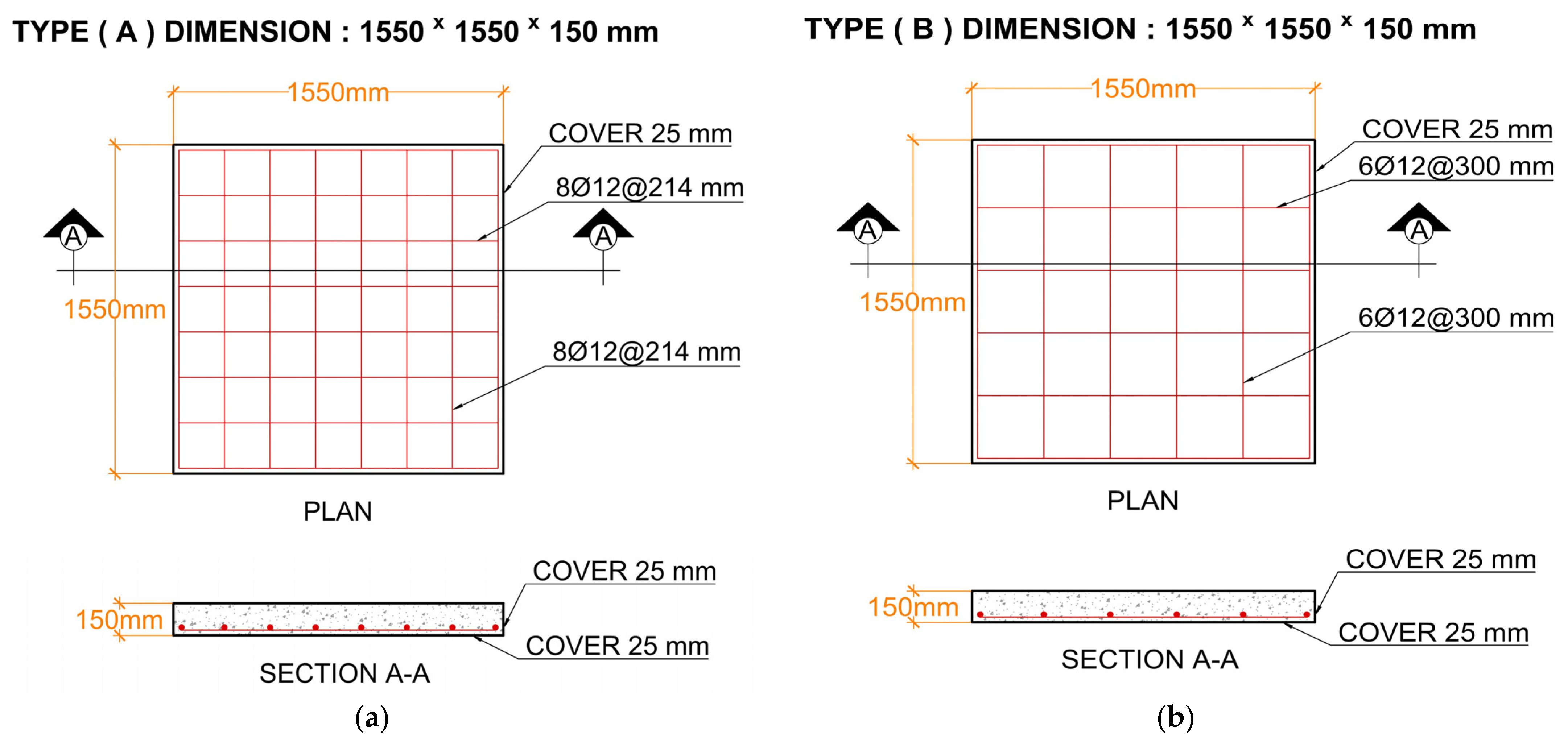
2.3. Specimen Design

Ten RC two-way flat solid slabs with a square-shaped geometry were tested for free drop weights from different heights, as presented in Table 4, using CFRP and traditional steel rebar as the internal reinforcements. Eight flat solid slabs were constructed using layered concrete consisting of 50% RPC as the 75 mm upper layer and 50% NC as the 75 mm lower layer, and two flat solid slabs were cast using 100% NC. The compressive strength of RPC and NC was 165.10 and 29.35 MPa, respectively, for the cylinder strength designs. Three parameters were varied amongst the slabs: slab reinforcement type: CFRP and steel; reinforcement ratio: 0.448 and 0.600; and the elevation of the drop weight: 5.0 m and 7.0 m. The slabs were (1550 × 1550 × 150) mm, reinforced with one mesh in the bottom tension layer. The slab reinforcement layout is presented in Figure 1.
The sample categorization systems are as follows. The letters R, S, H, and C represent the reference, steel reinforcement, hybrid layer-type concrete, and CFRPs, respectively. The numbers 6 and 8 denote the number of bars in each direction in the tension reinforcement grid that represent reinforcement ratios of 0.448 and 0.600, respectively. Finally, the values 5 and 7 represent the altitude from which the weight was dropped, namely at 5.0 and 7.0 m, respectively. For instance, specimen S8H7 indicates reinforcement with 8 steel bars, cast using hybrid layers, and tested by dropping the weight from 7.0 m.

2.4. Instrumentation

The dynamic response of the RC flat solid slabs to the impact loads was analyzed and evaluated depending on various kinds of sensory data, including two LVDTs; the first one (LVDT1) was positioned at the center, and the second (LVDT2) was positioned 300 mm from the corner of the slab at the bottom of the tested slabs. Preparations were made to preserve the LVDTs from damage due to the impact by placing them in a steel cover. Load cells of a 200 kN capacity were located at each corner of the steel frame, with a total of four, and were used to sense the impact weight reactions. The steel frame with a sample, the LVDTs, and the load cells is shown in Figure 2a,b. Along with the use of three Tokyo Measuring Instruments Laboratory (TML) strain gauges (one strain gauge attached to the reinforcements to measure the strain of the reinforcements and one strain gauge to calculate the strain of the concrete located on the bottom face of the specimen), the acceleration was also measured by an accelerometer (piezometer). The sensor signals were recorded by a high-speed data acquisition system, a National Instruments PXi-1000B chassis with four NI 6052E cards from the manufacturing company National Instruments Corporation, Texas, USA with a high frequency (20 MHz), capable of receiving signals from the load cell, the laser velocity, and information from the LVDTs through channel recording and analyzing the time variation in the voltage in two directions as signals.

2.5. Test Setup and Procedure

The customized steel frame with four load cell bases was fabricated to provide a hinge support condition and prevent rebounding upon impact; the impact test was carried out by utilizing free drop-weight impact loads on their centers using a total mass of 150 kg from a hardened steel cylindroconical impactor (projectile) with a height of 650 mm, a diameter of 200 mm, and a flat nose diameter of 90 mm. The drop weight was released from two different altitudes of 5.0 and 7.0 m and complied with the range of heights and weights of the drop mass used in previous studies [59,60,61,62]. As illustrated in Figure 2a–d, the impact tests were performed utilizing a specialized apparatus designed exclusively for these types of investigations.
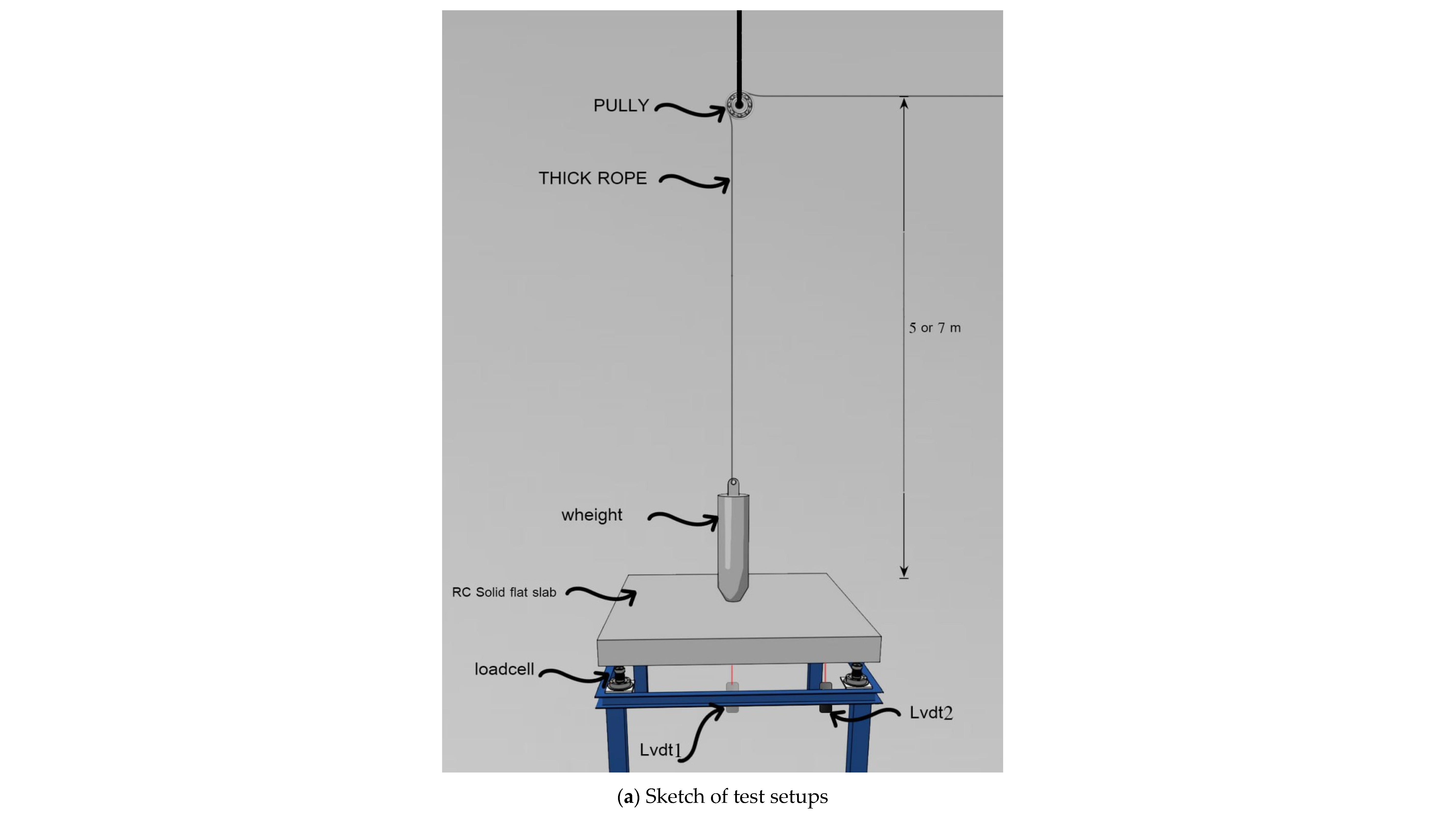
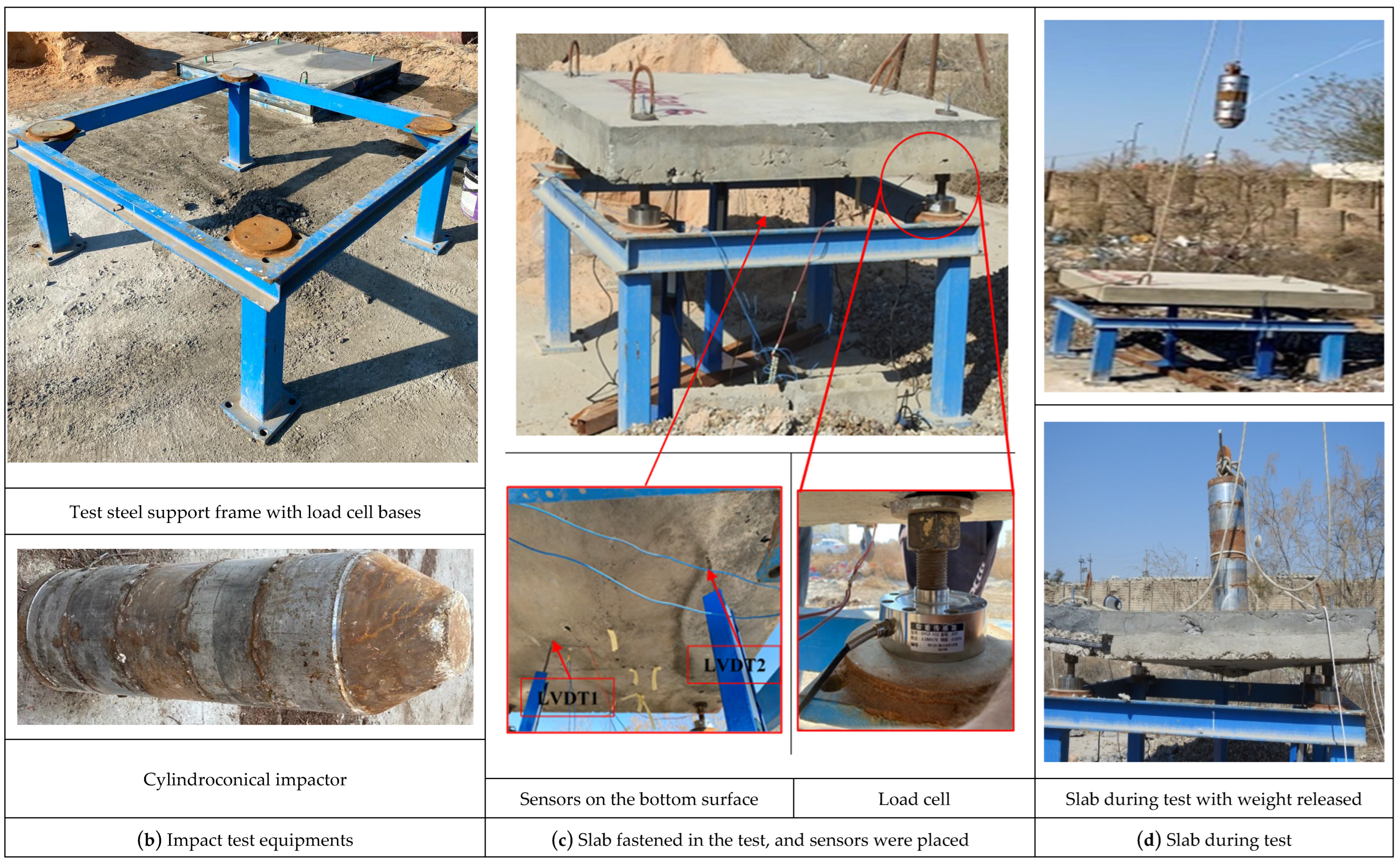
  • All specimens were subjected to the testing procedure described below; a sketch of the test setups and the actual test frame are illustrated in Figure 2a,b.
  • The slab is raised and positioned on the steel frame, putting the studs into the slab holes that were prepared through molding and tying the nuts to firmly fasten the slab onto the frame, as shown in Figure 2c.
  • Two concrete strain gauges and a piezometer are placed on the bottom surface of the slab (see Figure 2c).
  • Check each device and ensure all wires are connected to the data logger.
  • As shown in Figure 2d, the 150 kg mass is raised to the specified height and positioned so that it falls in the middle of the slab.
  • As soon as the 150 kg mass is released, the measuring devices are also activated, and all data during the fall process are recorded. The experiments are recorded by video with the camera placed under the steel frame to see the floor and the cameras placed to see the whole experimental setup.
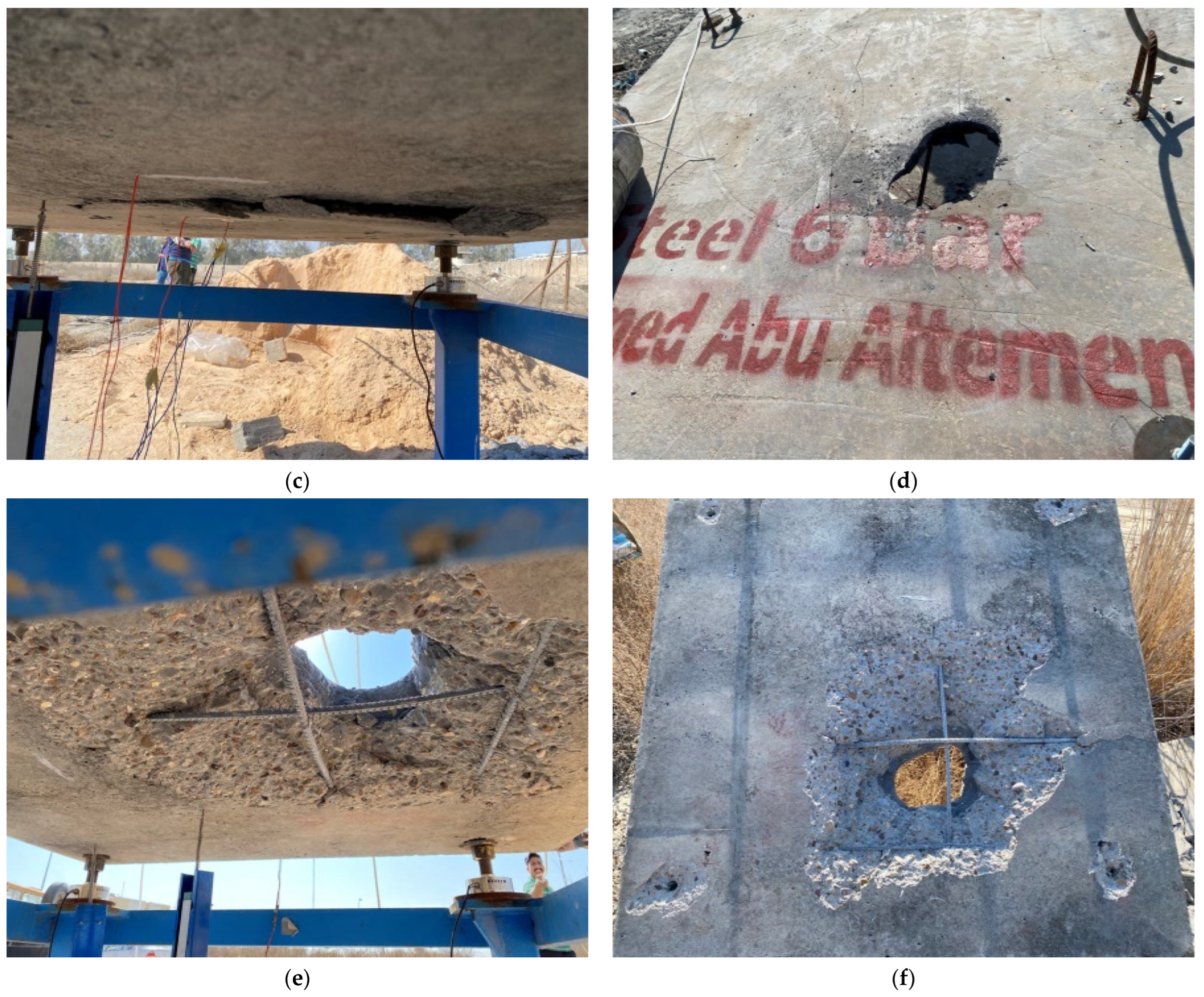
  • Repeat Steps 4 and 5 until the slab is penetrated, causing punching failure.

3. Experimental Test Results and Discussion

3.1. Observation of Impact Tests

This section demonstrates the visible monitoring of the impact tests as well as the crack patterns and failure modes caused by the weight dropping. The ultimate states of the slabs after the test are also discussed. Table 5 presents the number of drops for every slab tested. In general, all the specimens developed a similar crack pattern in both directions and exhibited punching shear failure. Furthermore, observation of the specimens’ crack patterns shows a decrease in cracks and micro-cracks between the NC slabs and hybrid layered slabs. It was found that the concrete in the impact zone on the top surface was not crushed during the first and second drops for the hybrid solid flat slabs in the first group or for the first drop in the second group, with micro-cracks only; however, all specimens showed a few cracks at failure that emerged around the penetration zone under the drop-weight impact compared to the NC specimens due to the increase in rigidity and their mechanical characteristics.
Also, the results revealed that using hybrid layer concrete increases the energy absorption. Moreover, it slightly decreased the dimensions of the failure area for most of the specimens compared to the control specimen with 100% NC due to the fine materials in the RPC mixture. The RPC, acting as a top layer, reduces the quantity of scattered concrete fragments and cracks caused by the impacts by absorbing the impact energy. RPC as a top layer made a significant improvement to the slab because the slab with 100% NC could not endure the third drop; on the other hand, the slabs with RPC sustained a third drop in the first group.
Therefore, it can be concluded that the utilization of RPC is superior for withstanding impact loads compared to NC. Correspondingly, RPC helped attain enhanced uniformity, excellent manipulability, strong compression, an improved microscopic structure, and high workability. Previous research has demonstrated that RPC is more susceptible to damage compared to NC, and this is consistent with the current study. Consequently, to enhance the structural integrity, NC was employed as the bottom layer. As a result, it was determined that future investigations should incorporate steel fibers into the mixture of RPC to improve the fragility of the RPC [63,64].
Upon visual inspection of the specimens, it was clearly noticed that there was excellent cohesive strength between the NC layer and the RPC layer after failure from observing the scattered falling concrete pieces, and this verifies this work by assuring us that the specimen layers acted as one layer with no interface debonding; the test observation is consistent with [65].

3.1.1. The R1 Specimen

The top face of the slab is shown in Figure 3a after each drop. On the first drop, the penetration was nearly 20 mm, with a diameter of 90 mm and with no cracks. The second drop caused full penetration, with a diameter of 180 mm on the upper face, with scattered pieces of concrete, with no cracks, and without bending of the reinforcement bars, which means that the concrete failed before the steel reinforcement. The shape of the failure is circular with a diameter of 500 mm, as shown in Figure 3a.

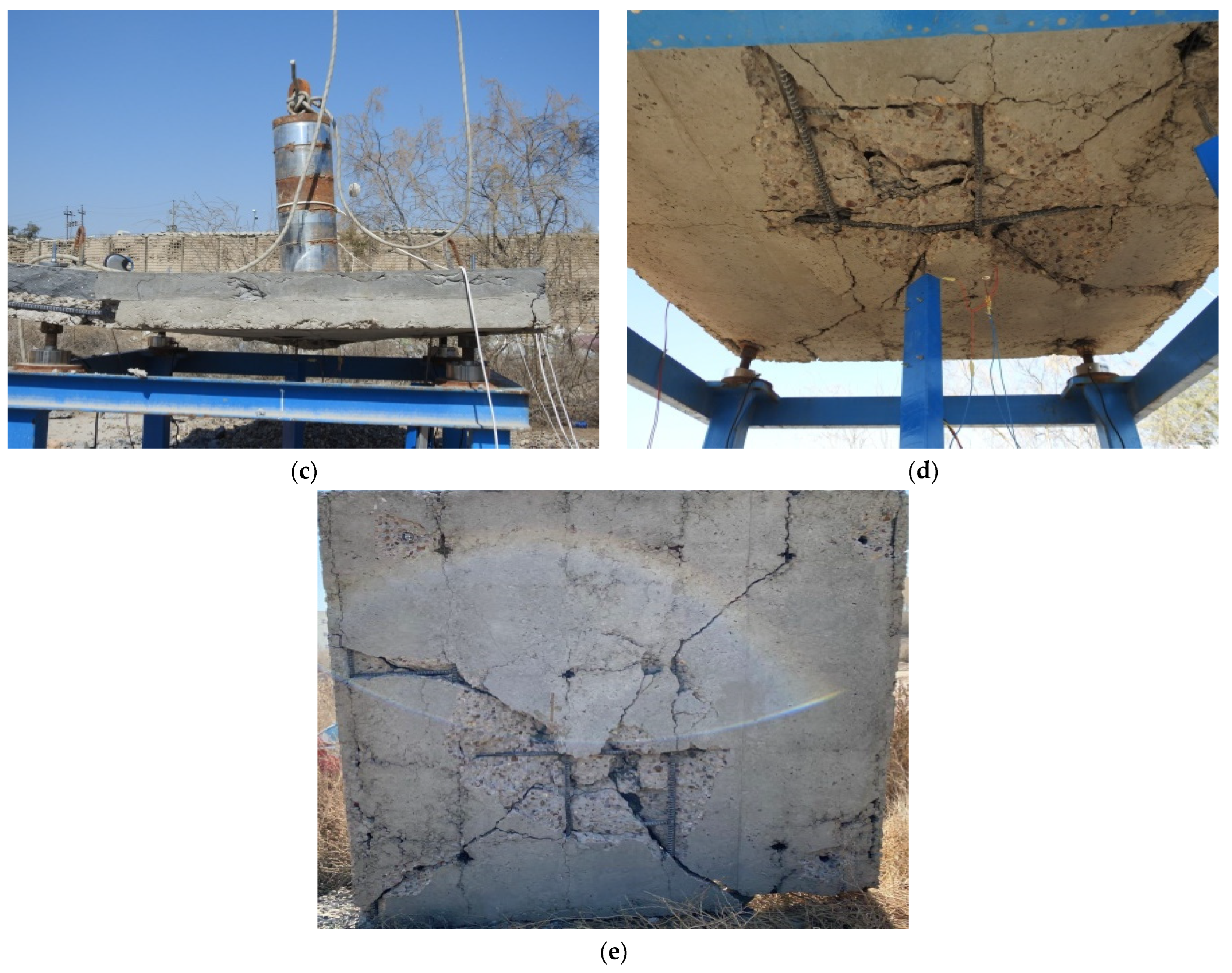
3.1.2. The S6H5 Specimen

On the first drop of the sample, the slab was not damaged; however, there was an impact on the top surface around 3 mm deep with a diameter the size of the flat nose of the steel projectile, as shown in Figure 4a. Also, we can see that the first drop produced circular cracks and concrete swelling on the lower side of the slab, but there was no concrete spalling or crashing, as shown in Figure 4b. The second drop caused partial penetration and was 35 mm deep with a diameter of 90 mm and with more circular cracks and concrete swelling on the lower side of the slab, as demonstrated in Figure 4c,d. The third drop fully penetrated with a 220 mm hole diameter into the upper face, accompanied by scattered pieces of concrete (only from the NC layer). There were no longitudinal or micro-cracks other than the penetration opening, and the steel reinforcement bars showed minor bending. The shape of the final crack pattern approached a circle, with a diameter of 590 mm, as seen in Figure 4e,f.

3.1.3. The S8H5 Specimen

On the first drop, the penetration was nearly 4 mm, with a diameter of 90 mm, into the top surface, with few narrow and hairline cracks on the lower side of the slab, as shown in Figure 5a and Figure 5b, respectively. On the second drop, the penetration was 30 mm with a diameter of 80 mm and with circular cracks on the top surface and concrete swelling on the lower side of the slab, as seen in Figure 5c. The third drop fully penetrated, with a diameter of 170 mm, into the upper face, with the bottom face undergoing full penetration and opening, scattered pieces of concrete with no longitudinal or micro-cracks except for the penetration opening, and a small amount of bending in the steel reinforcement bars. The shape of the failure on the bottom face approached a circle with a diameter of 630 mm, as shown in Figure 5d–g.

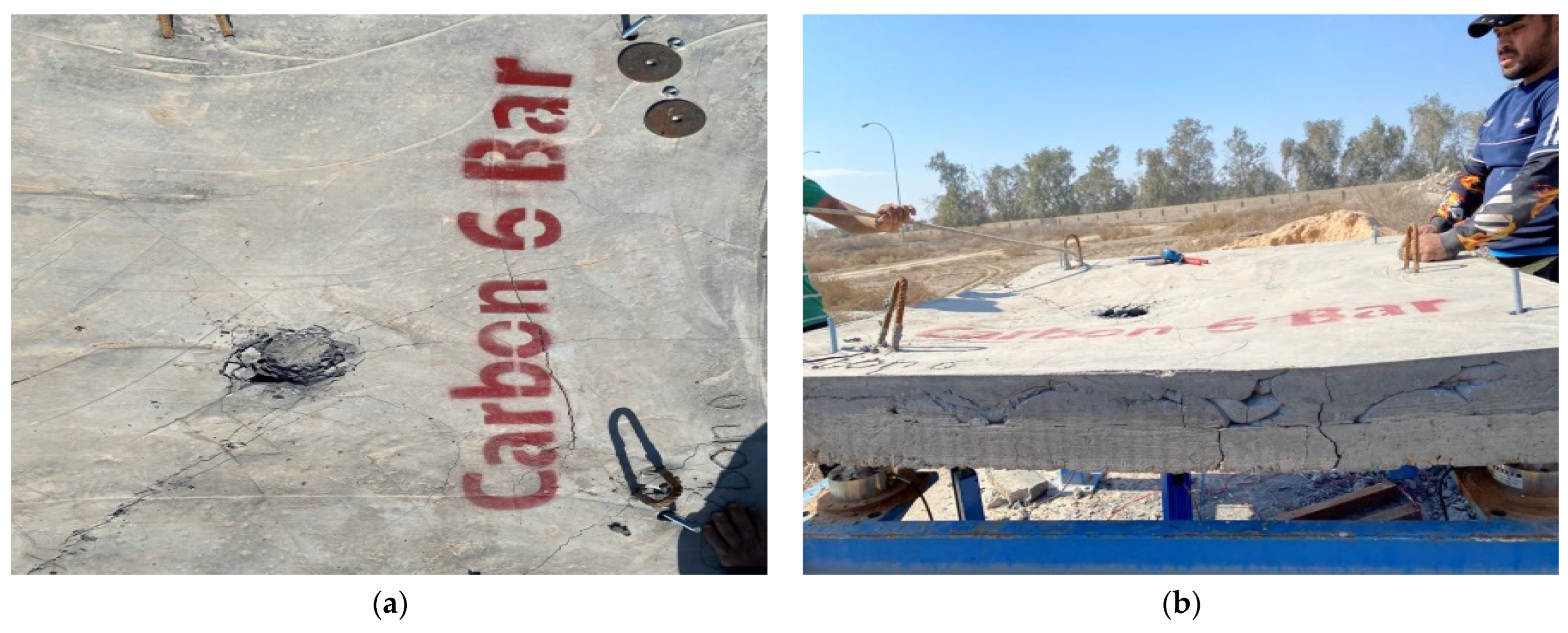
3.1.4. The C6H5 Specimen

The top and bottom faces of the C6H5 specimen are shown in Figure 6a–e after each drop. On the first drop, the penetration was nearly 9.0 mm, with a diameter of 110 mm and with micro-cracks appearing on the slab’s upper face. For the second drop, the penetration was 50 mm, with a diameter of 140 mm, a slight defect making a concave shape, and circular cracks and concrete swelling on the lower side of the slab. The third drop fully penetrated with a diameter of 190 mm into the upper face without making an opening, and small concrete pieces fell from the slab side, along with an increase in the concave defect shape, scattered pieces of concrete with longitudinal and micro-cracks, and a small amount of bending in the reinforcement bars. The shape of the failure was circular with a diameter of 560 mm, and flexural diagonal cracks were observed, as shown in Figure 6d,e.

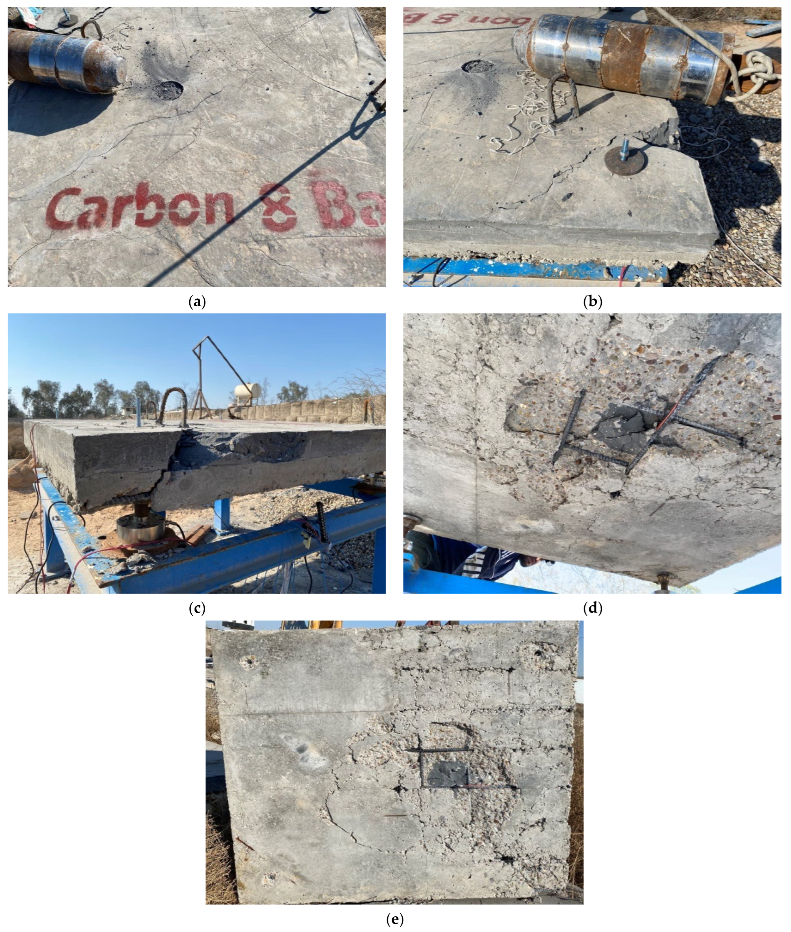
3.1.5. The C8H5 Specimen

As shown in Figure 7a–e, on the first drop, the penetration was nearly 4 mm, with a diameter of 90 mm and with micro-cracks appearing on the slab’s upper face. For the second drop, the penetration was 20 mm, with a diameter of 10 mm and damage to the slab’s corner. Circular cracks and concrete swelling were observed on the lower side of the slab. The third drop did not cause full penetration or an opening, and small concrete pieces spilled from the slab’s bottom side. Scattered pieces of concrete with circular and partial longitudinal and micro-cracks and no bending in the reinforcement bars were observed. The shape of the failure was circular, with a diameter of 660 mm, as demonstrated in Figure 7e.

3.1.6. The R2 Specimen

The top face of the R2 specimen is shown in Figure 8a after the first and second drops. On the first drop, the penetration was 50 mm with a diameter of 150 mm and with no micro-cracks appearing on the slab’s upper face. On the second drop, full penetration with a hole diameter of 200 mm occurred, generating scattered pieces of concrete with micro-cracks and a small amount of bending in the reinforcement bars. The shape of the failure was circular with a diameter of 470 mm, as shown in Figure 8a.

3.1.7. The S6H7 Specimen

As shown in Figure 9b, on the first drop, the penetration was 30 mm, with a diameter of 100 mm and with diagonal cracks and micro-cracks appearing on the slab’s upper face. Circular cracks and concrete swelling on the lower side of the slab were observed. For the second drop, the penetration was 60 mm, with a diameter of 150 mm and with more circular cracks and concrete swelling on the lower side of the slab. Also, scattered pieces of concrete (only from the NC layer) with no penetration opening and a small amount of bending in the reinforcement bars were noted. The second drop caused severe damage to the slab’s corner. The shape of the failure was circular with a diameter of 460 mm, as shown in Figure 9b.

3.1.8. The S8H7 Specimen

The top face of the S8H7 specimen is shown in Figure 10c after each drop. On the first drop, the penetration was 50 mm with a diameter of 140 mm and without any diagonal or micro-cracks appearing on the slab’s upper face. Circular cracks and concrete swelling on the lower side of the slab were noted. For the second drop, the penetration was 80 mm with a diameter of 180 mm. More circular cracks and concrete swelling on the lower side of the slab were noted. Scattered pieces of concrete (only from the NC layer) with no penetration opening and minimal bending in the reinforcement bars were also noted. The shape of the failure was circular with a diameter of 460 mm, as shown in Figure 10c.

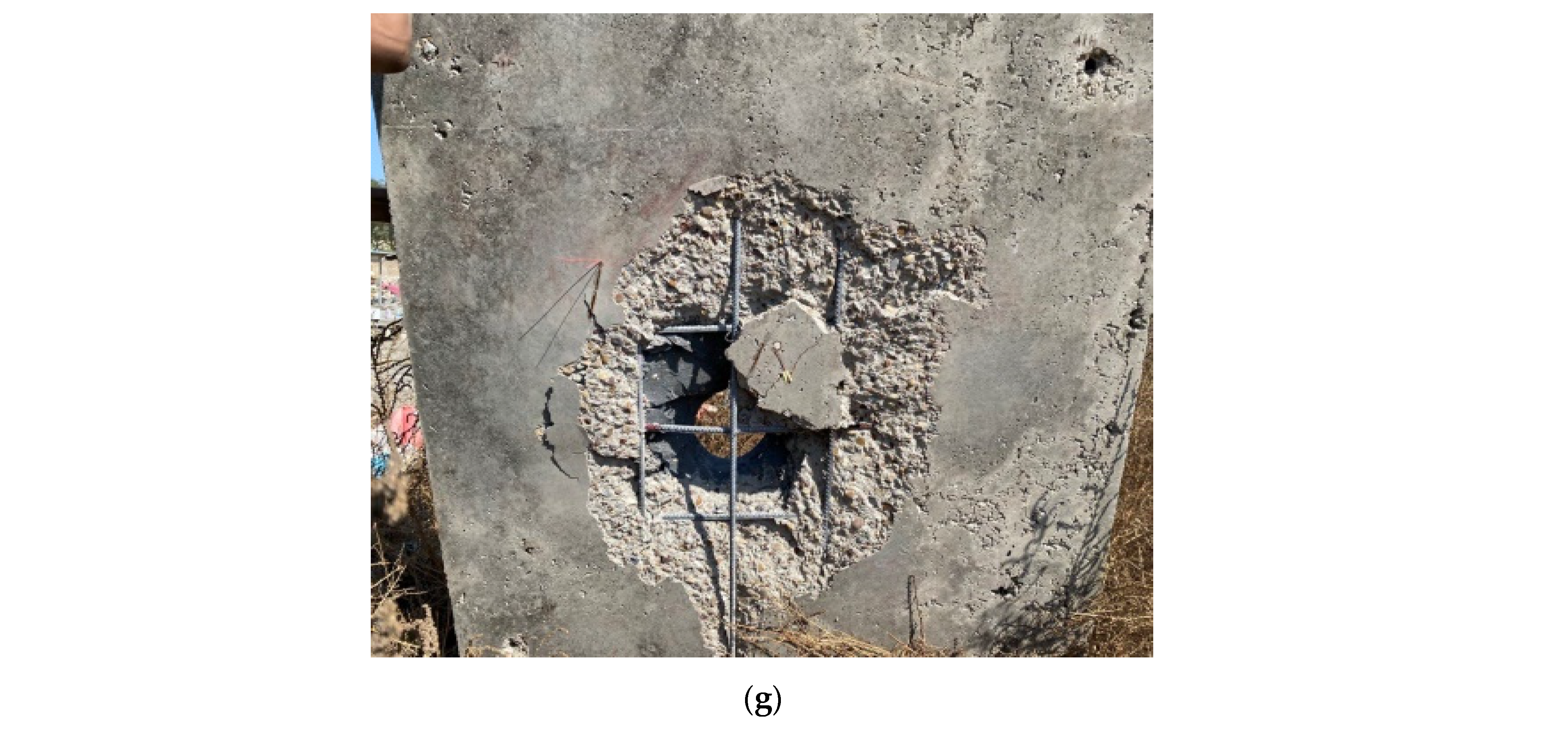
3.1.9. The C6H7 Specimen

As shown in Figure 11d, on the first drop, the penetration was 4 cm with a diameter of 12 cm and with micro-cracks appearing on the slab’s upper face. Circular cracks and concrete swelling on the lower side of the slab were noted. The second drop caused severe damage to the slab that did not happen to any other slab. Full penetration with cracks and micro-cracks on the bottom and upper side of the slabs with a huge falling concrete piece and cutting-in the reinforcement bars occurred due to using the minimum reinforcement ratio. The shape of the failure was square with dimensions of (600 × 600) mm, as shown in Figure 11d.

3.1.10. The C8H7 Specimen

The top face of the S8H7 specimen is shown in Figure 12c after each drop. After the first drop, the penetration was 15 mm, with a diameter of 90 mm, without micro-cracks appearing on the upper face, and with concrete swelling and circular micro-cracks on the lower side of the slab. The second drop penetrated through 25 mm of 110 mm. On the third drop, the penetration was 40 mm with a 130 mm diameter. After this drop, micro-cracks became visible on the upper face of the slab. The lower side was damaged without an opening; also, the shape of the failure was a half-circle with a diameter of 250 mm, as demonstrated in Figure 12e.

3.2. Deformation Behavior

The value of the displacement is higher with an increased number of drops until failure occurs, as shown in Figure 13 for each group’s results at the center (LVDT1) and 300 mm from the center (LVDT2) for the last drop at failure. Figure 14 presents a comparison between the specimens in group one and two; the comparison for group one did not include the control specimen because it failed before the other specimens (instead of looking to Figure 14, it is better to give the maximum deflection readings from LVDT1 and 2 for each drop). The ultimate deformation at the center LVDT of the R1 specimen was 43 mm at failure on the second drop, while it was 34 and 30 mm for the S6H5 and S8H5 specimens, respectively, for the same drop, which clearly shows enhancement of the resistance by using the RPC layer; RPC’s higher durability, ductility, and toughness made it an effective absorbing layer for impact loading [64]. Furthermore, it made the specimens endure a third drop that the NC-only specimens did not endure, and the ultimate deformation for those two slabs was 47.50 and 43.50 mm for the S6H5 and S8H5 specimens, respectively, on the third drop at failure. Deviation in the deformation readings was mainly attributed to the number of reinforcement bars and the RPC layer in the compressive zone. Abbas et al. [66] observed similar behavior when conducting an experimental investigation on the reinforcement bar spacing in concrete slabs subjected to projectile impacts. The ultimate deformation at the center LVDT of the C6H5 and C8H5 specimens was 33.50 and 29 mm, respectively, on the third drop at failure, which shows that using CFRP is substantially more influential in reducing the impact damage compared to steel reinforcement slabs with and without an RPC layer. This finding is in agreement with the findings of previous studies. CFRP rebar have been found to possess a higher strength-to-weight ratio and tensile strength than steel rebar, and they are also capable of resisting more shear forces than steel rebars, which necessitates the replacement of steel rebars with additional shear rebars in order to improve their punching resistance [67,68]. Comparison of the number of bars of the same type demonstrates a decrease in deflection at the mid-span for steel and CFRP. In the second group, the deformation readings increased due to the increase in the projectile drop height to 7 m, where the ultimate deflection reading for the R2 specimen was 64 mm on the second drop at failure, and it decreased for S6H7, S8H7, C6H7, and C8H7, which registered 53, 50, 43, and 41 mm, respectively, seeing that C8H7 did not fail on the second drop along with the other specimens and endured a third drop, which recorded a 51 mm deflection.

3.3. The Reinforcement Strain

Every specimen had a strain gauge attached to its reinforcement rebar to study the reinforcement strain–time history for the slab bars. The value of the reinforcement strain increased with an increase in the number of drops until failure occurred, as shown in the comparison of the specimen reinforcement strain results at failure in Figure 15 and Figure 16. Figure 17 presents a comparison between the specimens in groups one and two; the comparison of group one did not include the control specimen because it failed before the other specimens. Also, the comparison of the second group included the CFRP specimen C8H7, which failed one drop after the other specimens, so we took its second drop result for comparison. The lag between the arrival time of the strain waves at the front point and the back point of the column in the figures below is caused by the difference in the magnitude of the compressive strain and the difference in the slab reinforcements and concrete mixtures, which can be noticed by comparing all the hybrid slabs with the NC slabs. By comparing the strain gauge results for the steel reinforcements, with calculation of the steel reinforcement yield strain and the ultimate yield strain from Hooke’s law, it was determined that the values were equal to 0.0037 and 0.01 mm/mm [20]. This demonstrates that only the R1, R2, and S6H7 specimens exhibit plastic behavior without exceeding the ultimate strain. Visual observation of the tested specimens showed that all the steel rebars illustrated bending in the damaged area under the penetration zone. At the same time, the CFRP rebars did not exhibit bending or cuts, with only one exception, specimen C6H7, which showed a cut in the CFRP rebars. The strain gauge findings for the CFRP bars indicated that all the specimens had elastic behavior, suggesting that the superior tensile strength qualities of the CFRP bars were not completely exploited. When the compressive strength of the concrete remains constant, increasing the CFRP reinforcement ratio results in a decrease in the strain level of the CFRP bars and a decrease in the utilization rate of their tensile qualities. Due to the absence of yield points like those found in standard steel bars, CFRP bars do not undergo any yielding and instead sustain damage directly [69]. Through visual examination, it is evident that the bond performance between steel and concrete is superior, indicating a greater level of cooperative efficiency between the two materials. These two factors explain the decreased stress level of the CFRP.

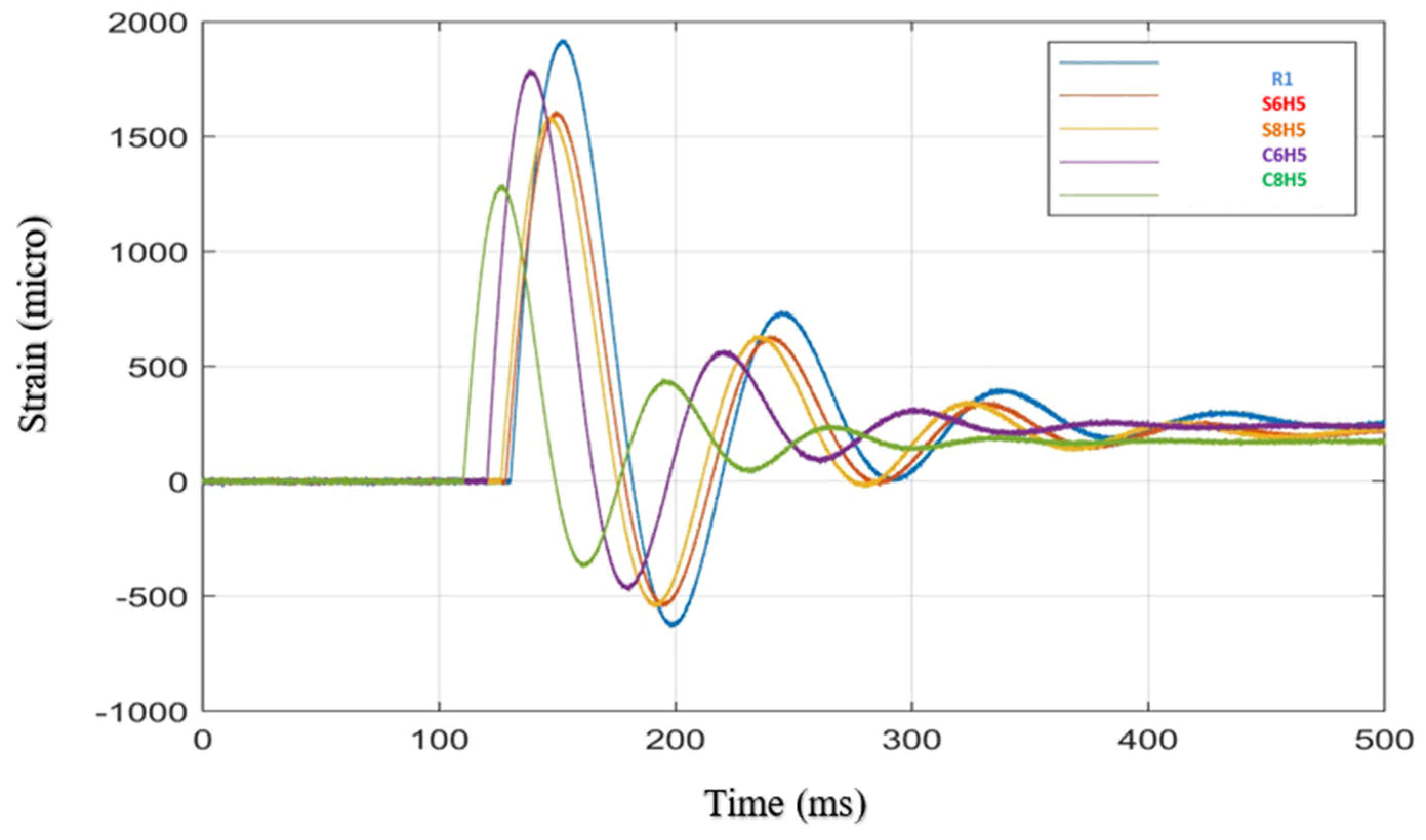
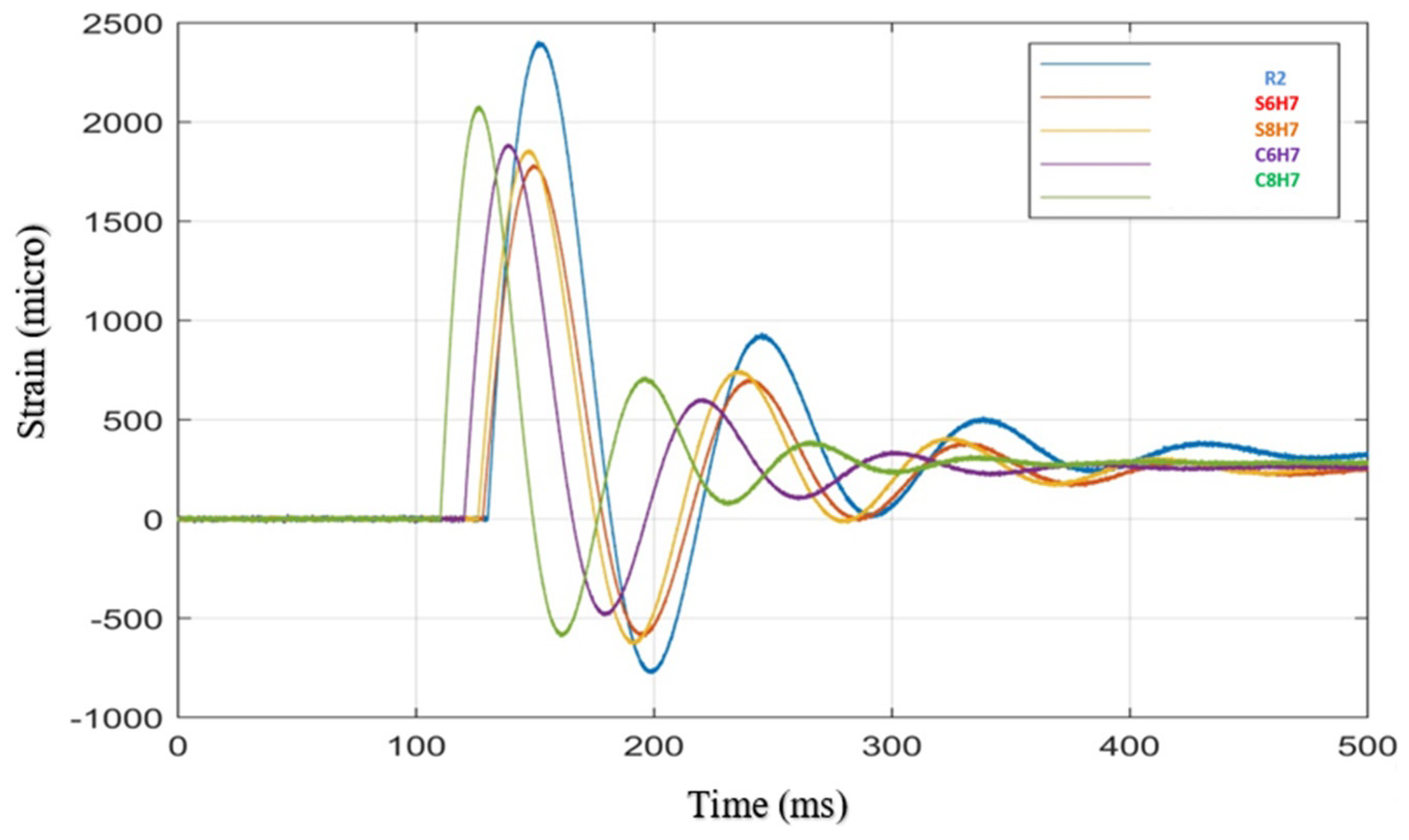
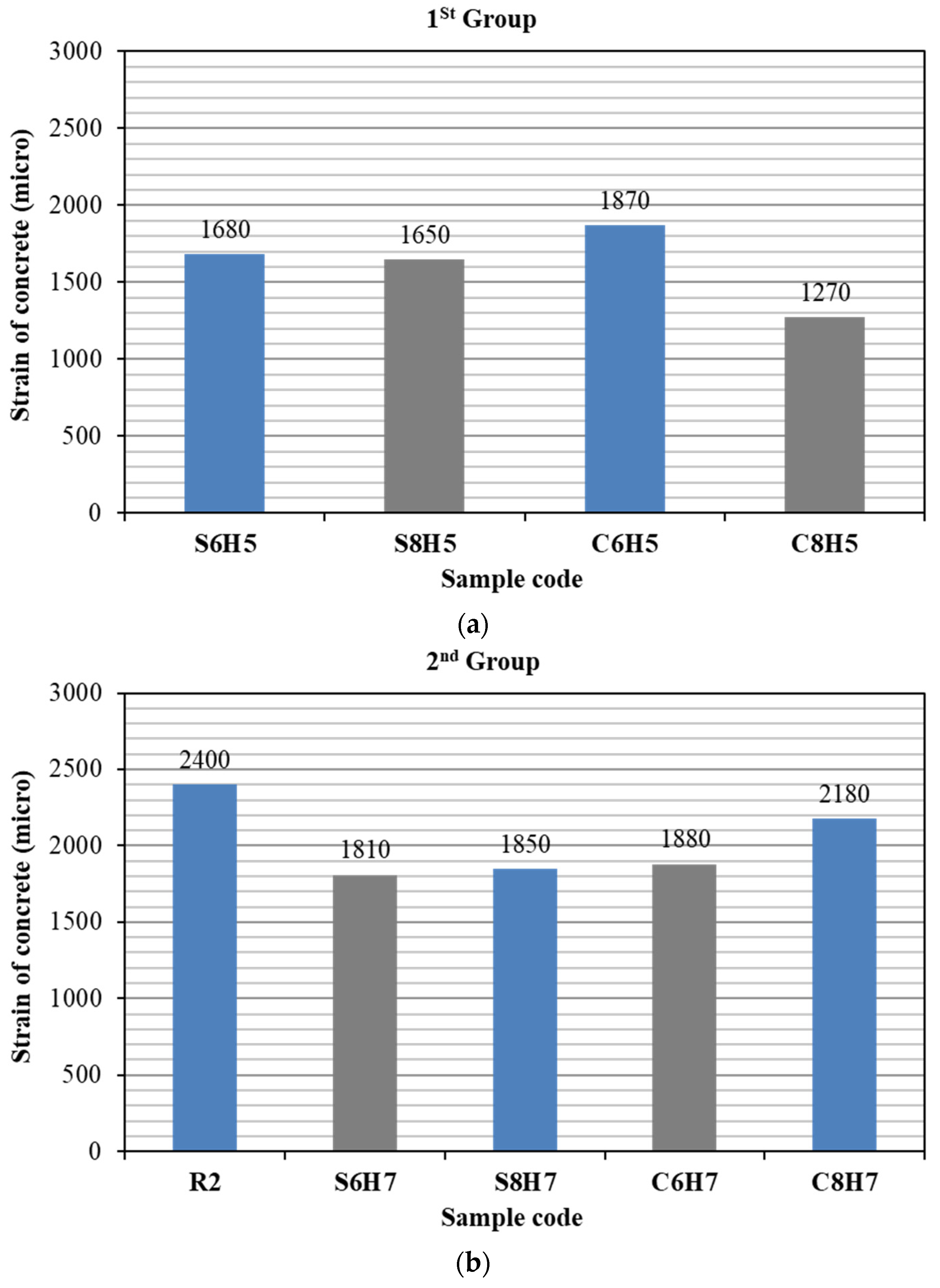
3.4. Strain of Concrete
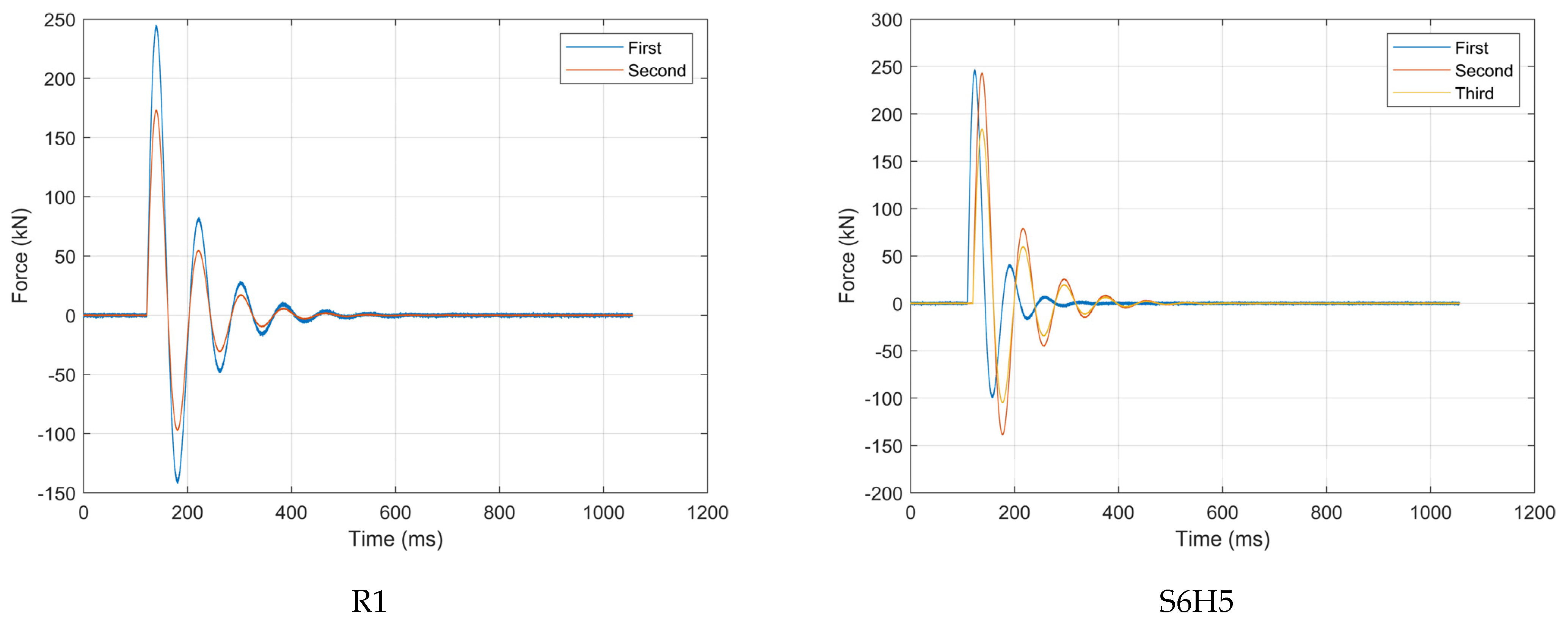
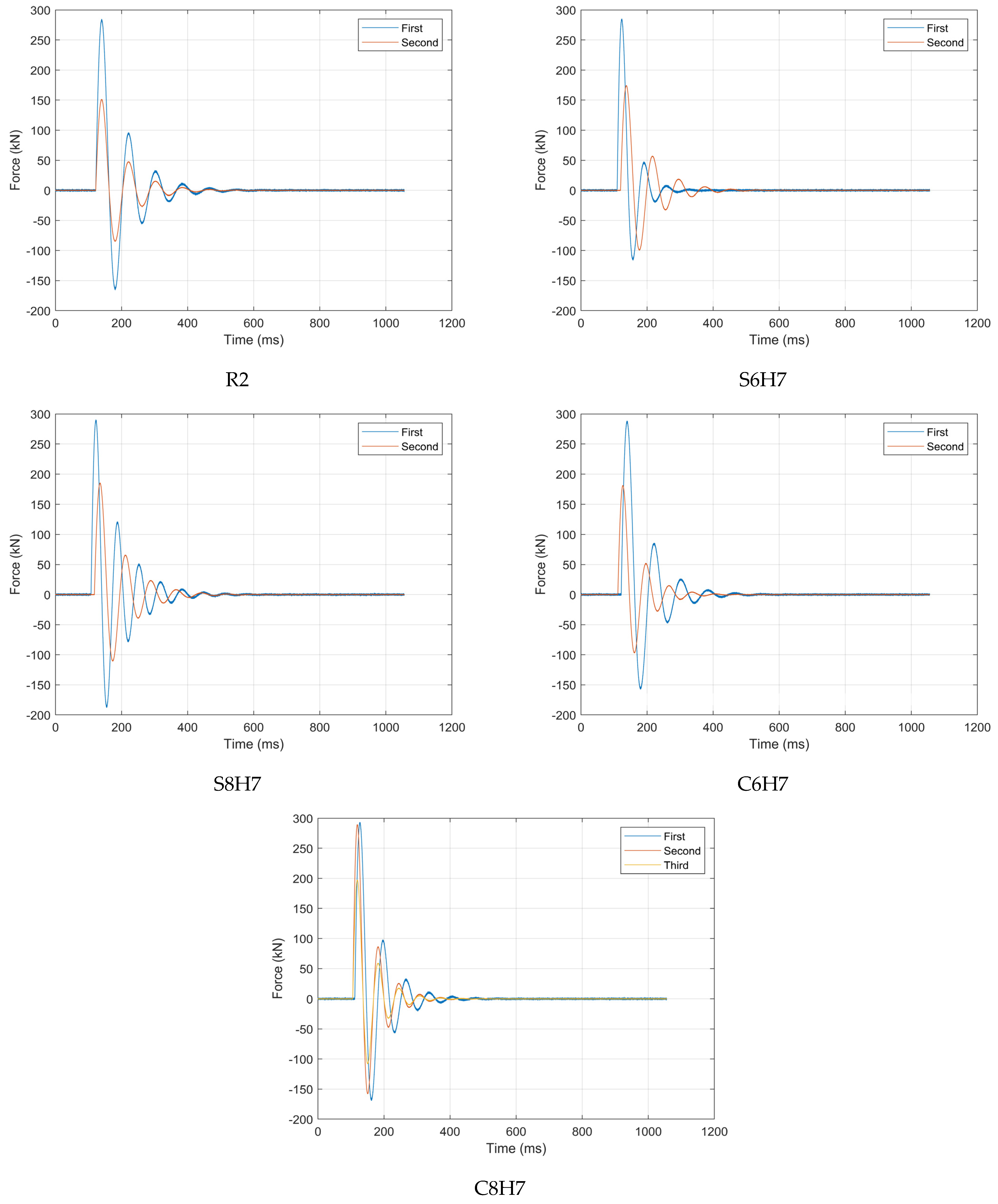
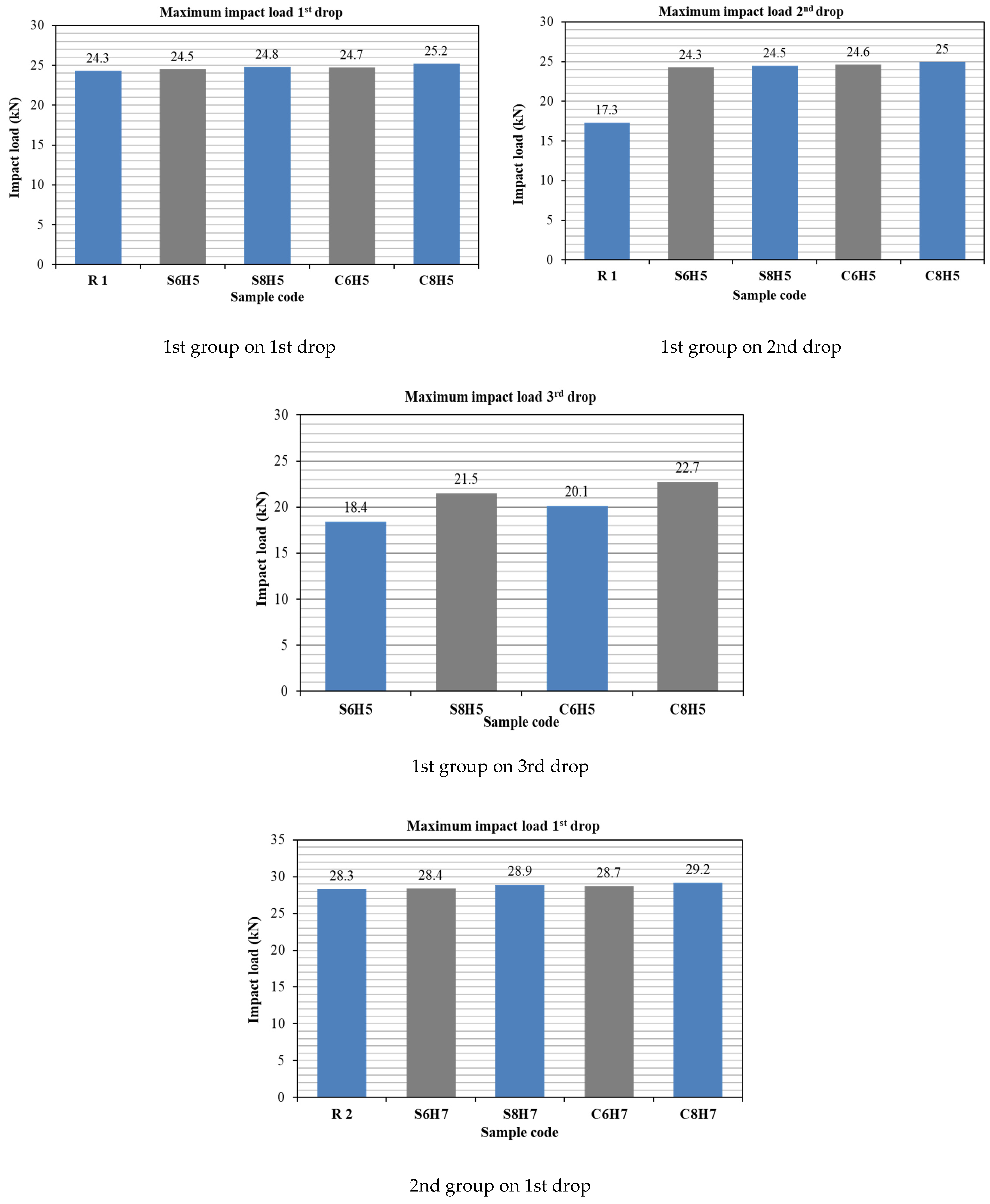
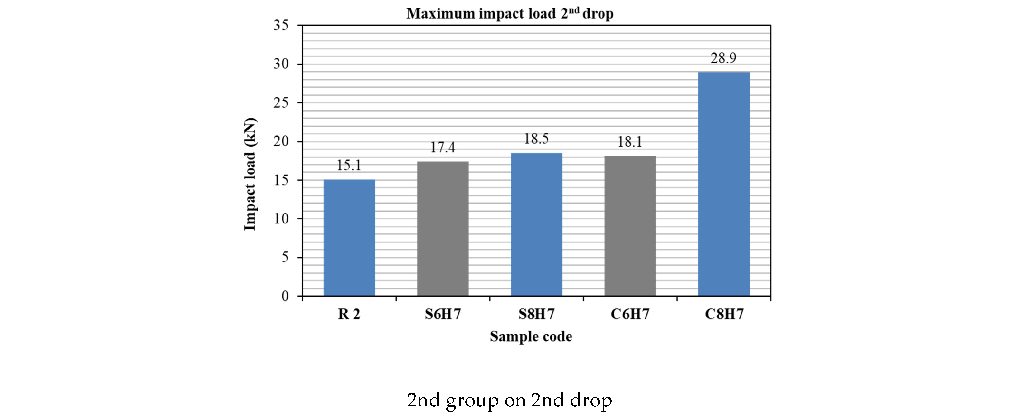
The concrete strain data results were obtained by placing strain gauges on the lower sides of the slabs near the center. The concrete strain values are very similar on the first drop; from then on, according to the number of drops, we see diverse results because they depend on the cracks created and their position after each strike, as shown in Figure 18, a specimen concrete strain result comparison at failure for group one, and Figure 19, that for group two. Figure 20 and Figure 21 present a comparison between the specimens in groups one and two; the comparison of group one did not include the control specimen because it failed before the other specimens. Also, the comparison of the second group included the specimen C8H7, which failed one drop after the other specimens, so we took its second drop result for comparison. Comparison of the specimens’ concrete strain curves exhibits a significant amount of variation and differences in the strain values because the strain values are dependent on the cracks that are created and their position after each strike and the concrete’s compressive strength.
The resulting concrete strain–time history for the first group shows that the RPC as a top layer made a significant improvement to the slab because the slab with 100% NC could not endure the third drop; on the other hand, the slabs with RPC sustained a third drop, meaning that using hybrid layer concrete increases impact energy absorption.

3.5. Impact Load

Impact force–time histories were recorded by four load cells (with a 500 kN capacity). A load cell was placed at each corner below the slabs, and when a mass was dropped on the specimen, the impact load was recorded, and this process was repeated until failure.
None of the specimens failed upon the first drop, so the number of strikes was increased until failure occurred in all specimens. The specimens in the first group failed after the third drop, except the control specimen, which failed after the second, and all the specimens in the second group failed after the second drop. After the first drop, the impact force was very similar in all the specimens, as shown in Figure 21 for each specimen in the 1st group and Figure 22 for each specimen in the 2nd group. Figure 23 presents a comparison between the specimens in group one and group two. Taking into consideration that the C8H7 specimen failed one drop after the other specimens in group two, its second drop results are compared. The adoption of a low percentage of reinforcement was to clearly demonstrate the failure and provide the hybrid concrete with an opportunity to show its performance under impact loads. Moreover, where the percentage of reinforcement increases with the strength of the hybrid concrete used in this experimental work, this will lead to an increase in the number of impacts required to reach failure. Therefore, it can be concluded that the utilization of RPC is superior in withstanding impact loads compared to NC. Correspondingly, RPC helped us attain enhanced uniformity, excellent manipulability, strong compression, an improved microscopic structure, and high workability. Previous research has demonstrated that RPC is more susceptible to damage compared to NC, and this is consistent with the current study [70].

4. Conclusions

Using layered concrete decreased the deflection at failure by an average of 12, 12.7, 14, and 16.2% for S6H5 and S6H7, S8H5 and S8H7, C6H5 and C6H7, and C8H5 and C8H7, respectively, compared to the control specimens R1 and R2. The third drop points to a huge enhancement because the control specimen did not endure the third drop; on the other hand, the slabs with RPC sustained a third drop with nearly the same percentages mentioned above. Using CFRP bars had a significant effect on deflection; it decreased the deflection at failure by an average of 10% compared to the slabs with steel bars. Increasing the reinforcement ratio of steel and CFRP decreased the deflection at failure by an average of 10.8 and 11.2% respectively. Improving the value of deflection is considered a fundamental player in preserving lives, as it increases the survival rate when the structure is exposed to impact loading.
  • Layered concrete helped decrease the strain in the reinforcement at failure by an average of 15.3, 20.5, 19.2, and 25.5% for S6H5, S8H5, C6H5, and C8H5, respectively, compared to R1, and that large difference in the percentage is because R1 failed after the second drop. Meanwhile, decreases of 3.8, 16.3, 8.4, and 27.3% were seen for S6H7, S8H7, C6H7, and C8H7, respectively, compared to R2, and that large difference in the percentage is because C8H7 sustained and endured a third drop. Using CFRP bars had a significant effect on strain; it decreased the strain at failure by an average of 5.5% compared to the slabs with steel bars. Increasing the reinforcement ratio of steel and CFRP decreased the strain at failure by an average of 7.2 and 16.9%, respectively.
  • Layered concrete helped decrease the strain in the concrete at failure by an average of 45.6, 34.3, 39, and 29.6% for S6H5, S8H5, C6H5, and C8H5, respectively, compared to R1, and that large difference in the percentage is because R1 failed after the second drop. Meanwhile, 9.2, 7.2, 5.7, and 35.8% decreases were recorded for S6H7, S8H7, C6H7, and C8H7, respectively, compared to R2, and that large difference in the percentage is because C8H7 sustained and endured a third drop, as well as because it depends on the cracks created and the position after each strike. Using CFRP bars had an important effect on the strain in the concrete; it decreased the strain at failure by an average of 5.5% compared to the slabs with steel bars. Increasing the reinforcement ratio of steel and CFRP had a variable outcome for each drop, but in general, the average decrease was 4.6 and 13.1%, respectively.
  • The RPC as a top layer helped to increase the specimens’ resistance by increasing the maximum impact load results at failure by an average of 40, 41.6, 42.1, and 44.5% for S6H5, S8H5, C6H5, and C8H5, respectively, compared to R1 and by 15.2, 22.5, 19.8, and 91.1% for S6H7, S8H7, C6H7, and C8H7, respectively, compared to R2, for the same reason mentioned earlier. Using CFRP bars increased the maximum impact load at failure by an average of 19% compared to the slabs with steel bars. Increasing the reinforcement ratio of steel and CFRP had a variable outcome for each drop, but in general, the average decrease was 11.6 and 36.2%, respectively. This issue can be explained by the increase in the cumulative strain values in the reinforcements, which led to an increase in the slabs’ resistance to impact loading.
  • C8H7 presented the best impact and deformation resistance results by far because it was the only slab that could endure and sustain a third drop and presented advanced results in all aspects during testing. These parameters can be further studied and improved for use in structures that are exposed to impact loading.

Author Contributions

Conceptualization, A.A.G.A.A.; methodology, M.K.M.; software, M.K.M.; validation, M.K.M. and M.Ö.; formal analysis, A.A.G.A.A.; investigation, A.A.G.A.A.; resources, A.A.G.A.A. and M.K.M.; data curation, A.A.G.A.A.; writing—original draft preparation, A.A.G.A.A.; writing—review and editing, A.A.G.A.A., M.K.M. and M.Ö.; visualization, A.A.G.A.A. and M.K.M.; supervision, M.Ö.; project administration, M.Ö.; funding acquisition, A.A.G.A.A. and M.K.M. All authors have read and agreed to the published version of the manuscript.

Funding

This research received no external funding.

Data Availability Statement

The datasets presented in this article are not readily available because privacy.

Acknowledgments

The authors would like to thank Mustansiriyah University and Gaziantep University for their support and assistance during this study work.

Conflicts of Interest

The authors declare no conflicts of interest.

List of Notations

ApCross-sectional area of CFRP strap
BSide length of flat solid slab
EcConcrete’s Young’s modulus
EpCFRP strap Young’s modulus
EsSteel’s Young’s modulus
fcConcrete (cylinder)’s compressive strength
fspConcrete’s tensile strength
frModulus of rupture
hSlab thickness
ØBar diameter
RPCReactive powder concrete
NCNormal concrete
RCReinforced concrete
FRPFiber-reinforced polymer
BFRPBasalt-Fiber-Reinforced Polymer
CFRPCarbon-fiber-reinforced polymer
ACIAmerican Concrete Institute
ASTMAmerican Society for Testing and Materials
LVDTLinear Variable Differential Transformer

References

  1. Kennedy, R.P. A Review of Procedures for the Analysis and Design of Concrete Structures to Resist Missile Impact Effects. Nucl. Eng. Des. 1976, 37, 183–203. [Google Scholar] [CrossRef]
  2. Said, A.I.; Mouwainea, E.M. Experimental Investigation on Reinforced Concrete Slabs under High-Mass Low Velocity Repeated Impact Loads. Structures 2022, 35, 314–324. [Google Scholar] [CrossRef]
  3. Al-Dala’ien, R.N.; Syamsir, A.; Abu Bakar, M.S.; Usman, F.; Abdullah, M.J. Failure Modes Behavior of Different Strengthening Types of RC Slabs Subjected to Low-Velocity Impact Loading: A Review. J. Compos. Sci. 2023, 7, 246. [Google Scholar] [CrossRef]
  4. Han, Z.; Qu, W.; Zhu, P. Research on Hybrid FRP–Steel-Reinforced Concrete Slabs under Blast Load. Buildings 2023, 13, 1058. [Google Scholar] [CrossRef]
  5. Elmessalami, N.; El Refai, A.; Abed, F. Fiber-Reinforced Polymers Bars for Compression Reinforcement: A Promising Alternative to Steel Bars. Constr. Build. Mater. 2019, 209, 725–737. [Google Scholar] [CrossRef]
  6. Böer, P.; Holliday, L.; Kang, T.H.-K. Independent Environmental Effects on Durability of Fiber-Reinforced Polymer Wraps in Civil Applications: A Review. Constr. Build. Mater. 2013, 48, 360–370. [Google Scholar] [CrossRef]
  7. Ahmed, S.F.U.; Maalej, M. Tensile Strain Hardening Behaviour of Hybrid Steel-Polyethylene Fibre Reinforced Cementitious Composites. Constr. Build. Mater. 2009, 23, 96–106. [Google Scholar] [CrossRef]
  8. Kadhim, S.; Özakça, M. Flexural Performance of RC Beams Externally Strengthened with a Single-Layer of Basalt Fiber Reinforced Polymer Sheets. Compos. Adv. Mater. 2022, 31, 26349833221102470. [Google Scholar] [CrossRef]
  9. Jin, L.; Yang, J.; Zhang, R.; Du, X. Modeling of GFRP-Reinforced Concrete Slabs under Various Impact Masses and Velocities. Thin-Walled Struct. 2023, 182, 110175. [Google Scholar] [CrossRef]
  10. Afroughsabet, V.; Biolzi, L.; Ozbakkaloglu, T. Influence of Double Hooked-End Steel Fibers and Slag on Mechanical and Durability Properties of High Performance Recycled Aggregate Concrete. Compos. Struct. 2017, 181, 273–284. [Google Scholar] [CrossRef]
  11. Jang, S.-J.; Yun, H.-D. Combined Effects of Steel Fiber and Coarse Aggregate Size on the Compressive and Flexural Toughness of High-Strength Concrete. Compos. Struct. 2018, 185, 203–211. [Google Scholar] [CrossRef]
  12. Mina, A.L.; Petrou, M.F.; Trezos, K.G. Resistance of an Optimized Ultra-High Performance Fiber Reinforced Concrete to Projectile Impact. Buildings 2021, 11, 63. [Google Scholar] [CrossRef]
  13. Liu, J.; Li, J.; Fang, J.; Su, Y.; Wu, C. Ultra-High Performance Concrete Targets against High Velocity Projectile Impact—A-State-of-the-Art Review. Int. J. Impact Eng. 2022, 160, 104080. [Google Scholar] [CrossRef]
  14. Ranade, R.; Li, V.C.; Heard, W.F.; Williams, B.A. Impact Resistance of High Strength-High Ductility Concrete. Cem. Concr. Res. 2017, 98, 24–35. [Google Scholar] [CrossRef]
  15. Goswami, A.; Das Adhikary, S.; Li, B. Predicting the Punching Shear Failure of Concrete Slabs under Low Velocity Impact Loading. Eng. Struct. 2019, 184, 37–51. [Google Scholar] [CrossRef]
  16. Kumar, V.; Iqbal, M.A.; Mittal, A.K. Experimental Investigation of Prestressed and Reinforced Concrete Plates under Falling Weight Impactor. Thin-Walled Struct. 2018, 126, 106–116. [Google Scholar] [CrossRef]
  17. Hrynyk, T.D.; Vecchio, F.J. Behavior of Steel Fiber-Reinforced Concrete Slabs under Impact Load. Struct. J. 2014, 111, 1213–1224. [Google Scholar] [CrossRef]
  18. Kušter Marić, M.; Ivanović, A.; Fusić, M.; Srbić, M.; Vlašić, A. Experimental Investigation of the Explosion Effects on Reinforced Concrete Slabs with Fibers. Buildings 2024, 14, 1080. [Google Scholar] [CrossRef]
  19. Arna’ot, F.H.; Abbass, A.A.; Abualtemen, A.A.; Abid, S.R.; Özakça, M. Residual Strength of High Strength Concentric Column-SFRC Flat Plate Exposed to High Temperatures. Constr. Build. Mater. 2017, 154, 204–218. [Google Scholar] [CrossRef]
  20. American Concrete Institute ACI Committee 318. Building Code Requirements for Structural Concrete ACI Committee 318; American Concrete Institute: Farmington Hills, MI, USA, 2014; ISBN 9781942727118. [Google Scholar]
  21. Whittle, R.; Taylor, H. Design of Hybrid Concrete Buildings: A Guide to the Design of Buildings Combining in-Situ and Precast Concrete; MPA The Concrete Centre: London, UK, 2009. [Google Scholar]
  22. Sada, M.J.; Resan, F.S. Shear Performance of Hybrid Concrete Deep Beams of Trapezoidal Section. IOP Conf. Ser. Mater. Sci. Eng. 2021, 1067, 12015. [Google Scholar] [CrossRef]
  23. Ruan, X.; Lu, C.; Xu, K.; Xuan, G.; Ni, M. Flexural Behavior and Serviceability of Concrete Beams Hybrid-Reinforced with GFRP Bars and Steel Bars. Compos. Struct. 2020, 235, 111772. [Google Scholar] [CrossRef]
  24. Zhou, B.; Wu, R.-Y.; Liu, Y.; Zhang, X.; Yin, S. Flexural Strength Design of Hybrid FRP-Steel Reinforced Concrete Beams. Materials 2021, 14, 6400. [Google Scholar] [CrossRef]
  25. Fall, D.; Lundgren, K.; Rempling, R.; Gylltoft, K. Reinforcing Tailor-Made Concrete Structures: Alternatives and Challenges. Eng. Struct. 2012, 44, 372–378. [Google Scholar] [CrossRef]
  26. Mohammed, N.S.; Hamza, B.A.; Al-Shareef, N.H.; Hussein, H.H. Structural Behavior of Reinforced Concrete Slabs Containing Fine Waste Aggregates of Polyvinyl Chloride. Buildings 2021, 11, 26. [Google Scholar] [CrossRef]
  27. Shill, S.K.; Garcez, E.O.; Al-Ameri, R.; Subhani, M. Performance of Two-Way Concrete Slabs Reinforced with Basalt and Carbon FRP Rebars. J. Compos. Sci. 2022, 6, 74. [Google Scholar] [CrossRef]
  28. Abdullah, A.H.; Abdulkadir, M.R. Flexural Behavior of One-Way Concrete Slabs Reinforced with Combined Steel-CFRP Bars. Arab. J. Sci. Eng. 2022, 47, 12963–12978. [Google Scholar] [CrossRef]
  29. Madkour, H.; Abd-Elraheem, S.R.; Ali, O. Numerical Damage Investigation for RC Slab-Column Connections. Ain Shams Eng. J. 2021, 12, 241–258. [Google Scholar] [CrossRef]
  30. Wu, Z.J.; Ye, J.Q. Strength and Fracture Resistance of FRP Reinforced Concrete Flexural Members. Cem. Concr. Compos. 2003, 25, 253–261. [Google Scholar] [CrossRef]
  31. Alsayed, S.H.; Al-Salloum, Y.A.; Almusallam, T.H. Performance of Glass Fiber Reinforced Plastic Bars as a Reinforcing Material for Concrete Structures. Compos. Part B Eng. 2000, 31, 555–567. [Google Scholar] [CrossRef]
  32. American Concrete Institute ACI Committee 440. Report on Fiber Reinforced Polymer (FRP) Reinforcement for Concrete Structures; American Concrete Institute: Farmington Hills, MI, USA, 2007. [Google Scholar]
  33. Elgabbas, F.; Ahmed, E.A.; Benmokrane, B. Flexural Behavior of Concrete Beams Reinforced with Ribbed Basalt-FRP Bars under Static Loads. J. Compos. Constr. 2017, 21, 04016098. [Google Scholar] [CrossRef]
  34. Bisby, L.A.; Chen, J.-F.; Li, S.Q.; Stratford, T.J.; Cueva, N.; Crossling, K. Strengthening Fire-Damaged Concrete by Confinement with Fibre-Reinforced Polymer Wraps. Eng. Struct. 2011, 33, 3381–3391. [Google Scholar] [CrossRef]
  35. Radnić, J.; Matešan, D.; Grgić, N.; Baloević, G. Impact Testing of RC Slabs Strengthened with CFRP Strips. Compos. Struct. 2015, 121, 90–103. [Google Scholar] [CrossRef]
  36. Li, Y.L.; Zhao, X.L.; Singh Raman, R.K.; Al-Saadi, S. Thermal and Mechanical Properties of Alkali-Activated Slag Paste, Mortar and Concrete Utilising Seawater and Sea Sand. Constr. Build. Mater. 2018, 159, 704–724. [Google Scholar] [CrossRef]
  37. Silwal, P.K.; Parvin, A.; Alhusban, M. Numerical Investigation on Strengthening of Steel Beams for Corrosion Damage or Web Openings Using Carbon Fiber Reinforced Polymer Sheets. Buildings 2024, 14, 1069. [Google Scholar] [CrossRef]
  38. Yılmaz, T.; Kıraç, N.; Anil, Ö.; Tuğrul Erdem, R.; Sezer, C. Low-Velocity Impact Behaviour of Two Way RC Slab Strengthening with CFRP Strips. Constr. Build. Mater. 2018, 186, 1046–1063. [Google Scholar] [CrossRef]
  39. Emara, M.; Hamoda, A.; Hu, J.W. Numerical Assessment of Rectangular One-and Two-Way RC Slabs Strengthened with CFRP under Impact Loads. Comput. Concr. 2023, 31, 173. [Google Scholar]
  40. Zhang, C.; Li, Y.; Wu, J. Mechanical Properties of Fiber-Reinforced Polymer (FRP) Composites at Elevated Temperatures. Buildings 2022, 13, 67. [Google Scholar] [CrossRef]
  41. Granata, M.F. Seismic Retrofit of Concrete Buildings Damaged by Corrosion: A Case Study in Southern Italy. Buildings 2024, 14, 1064. [Google Scholar] [CrossRef]
  42. Kodur, V.K.R.; Bhatt, P.P.; Naser, M.Z. High Temperature Properties of Fiber Reinforced Polymers and Fire Insulation for Fire Resistance Modeling of Strengthened Concrete Structures. Compos. Part B Eng. 2019, 175, 107104. [Google Scholar] [CrossRef]
  43. Alwash, N.A.A.; Habeeb, G.M.; Al-Mamoori, F.H.N. Flexural Behavior of Light Weight Concrete Slab Panels Reinforced With CFRP Bars. Al-Qadisiyah, J. Eng. Sci. 2017, 10, 368–383. [Google Scholar]
  44. Medhlom, M.K.; Abed, E.N. Behavior and Load Capacity of Concrete Slab Reinforced by CFRP Bar and Strengthening by CFRP Laminates. Civ. Environ. Eng. 2023, 19, 72–85. [Google Scholar] [CrossRef]
  45. Dheyab, M.A.; Mu’taz, K. Numerical Evaluation of Slab Thickness Effect on The Impact Behavior of Concrete Slabs Reinforced With CFRP Bars. J. Eng. Sustain. Dev. 2021, 25, 4-57–4-68. [Google Scholar] [CrossRef]
  46. Emara, M.; Elkomy, N.; Kader, H.A. Numerical Assessment of Reinforced Concrete Beams Strengthened with CFRP Sheets under Impact Loading. Frat. Ed Integrità Strutt. 2021, 15, 48–64. [Google Scholar] [CrossRef]
  47. Hamoda, A.; Hossain, K.M.A. Numerical Assessment of Slab--Column Connection Additionally Reinforced with Steel and CFRP Bars. Arab. J. Sci. Eng. 2019, 44, 8181–8204. [Google Scholar] [CrossRef]
  48. Liao, J.; Zeng, J.-J.; Lin, X.-C.; Zhuge, Y.; He, S.-H. Punching Shear Behavior of FRP Grid-Reinforced Ultra-High Performance Concrete Slabs. J. Compos. Constr. 2023, 27, 4023031. [Google Scholar] [CrossRef]
  49. Zeng, J.-J.; Zeng, W.-B.; Ye, Y.-Y.; Liao, J.; Zhuge, Y.; Fan, T.-H. Flexural Behavior of FRP Grid Reinforced Ultra-High-Performance Concrete Composite Plates with Different Types of Fibers. Eng. Struct. 2022, 272, 115020. [Google Scholar] [CrossRef]
  50. ASTM C 150; Standard Specification for Portland Cement. ASTM International: West Conshohocken, PA, USA, 2022.
  51. ASTM C 1240; Standard Specification for Silica Fume Used in Cementitious Mixtures. ASTM International: West Conshohocken, PA, USA, 2020.
  52. ASTM C 33; Standard Specification for Concrete Aggregates. ASTM International: West Conshohocken, PA, USA, 2018.
  53. ASTM C 494; Standard Specification for Chemical Admixtures for Concrete 11. ASTM International: West Conshohocken, PA, USA, 2018; pp. 1–10.
  54. ASTM A 615; Standard Specification for Deformed and Plain Carbon-Steel Bars for Concrete Reinforcement. ASTM International: West Conshohocken, PA, USA, 2016.
  55. ASTM C 39; Standard Test Method for Compressive Strength of Cylindrical Concrete Specimens. ASTM International: West Conshohocken, PA, USA, 2018; pp. 1–5.
  56. ASTM C 496; Standard Test Method for Splitting Tensile Strength of Cylindrical Concrete Specimens. ASTM International: West Conshohocken, PA, USA, 2011; pp. 1–5.
  57. ASTM C 469; Standard Test Method for Static Modulus of Elasticity and Poisson’s Ratio of Concrete in Compression. ASTM International: West Conshohocken, PA, USA, 2014.
  58. ASTM C 293; Standard Test Method for Flexural Strength of Concrete (Using Simple Beam With Center-Point Loading). ASTM International: West Conshohocken, PA, USA, 2016.
  59. Zhu, X.-C.; Zhu, H.; Li, H.-R. Drop-Weight Impact Test on U-Shape Concrete Specimens with Statistical and Regression Analyses. Materials 2015, 8, 5877–5890. [Google Scholar] [CrossRef]
  60. Zhang, W.; Chen, S.; Liu, Y. Effect of Weight and Drop Height of Hammer on the Flexural Impact Performance of Fiber-Reinforced Concrete. Constr. Build. Mater. 2017, 140, 31–35. [Google Scholar] [CrossRef]
  61. Mizushima, Y.; Iino, N. Behavior of Thin Reinforced Concrete Slabs and Effect of Reinforcement Bars Subjected Low-Velocity Impact. Structures 2022, 38, 832–847. [Google Scholar] [CrossRef]
  62. Hummeltenberg, A.; Beckmann, B.; Weber, T.; Curbach, M. Investigation of Concrete Slabs under Impact Load. Appl. Mech. Mater. 2011, 82, 398–403. [Google Scholar] [CrossRef]
  63. Tai, Y.-S.; Tang, C.-C. Reactive Powder Concrete Plate Response to a Flat Projectile Impact. WIT Trans. Built Environ. 2006, 87, 10. [Google Scholar]
  64. Sanjuán, M.Á.; Andrade, C. Reactive Powder Concrete: Durability and Applications. Appl. Sci. 2021, 11, 5629. [Google Scholar] [CrossRef]
  65. Xu, L.; Yao, Y.; Li, Y.; Su, J.; Wu, Y. Review of the Interfacial Bonding Properties between Ultrahigh-Performance Concrete and Normal Concrete. Appl. Sci. 2023, 13, 6697. [Google Scholar] [CrossRef]
  66. Abbas, H.; Siddiqui, N.A.; Almusallam, T.H.; Abadel, A.A.; Elsanadedy, H.; Al-Salloum, Y.A. Effect of Rebar Spacing on the Behavior of Concrete Slabs under Projectile Impact. Struct. Eng. Mech. 2021, 77, 329–342. [Google Scholar]
  67. Amran, Y.H.M.; Alyousef, R.; Rashid, R.S.M.; Alabduljabbar, H.; Hung, C.-C. Properties and Applications of FRP in Strengthening RC Structures: A Review. Structures 2018, 16, 208–238. [Google Scholar] [CrossRef]
  68. Huang, Z.; Zhao, Y.; Zhang, J.; Wu, Y. Punching Shear Behaviour of Concrete Slabs Reinforced with CFRP Grids. Structures 2020, 26, 617–625. [Google Scholar] [CrossRef]
  69. Bakar, M.B.C.; Rashid, R.S.M.; Amran, M.; Jaafar, M.S. Evaluation of the Bond-Dependent Factors for CFRP Bars Used as Structural Reinforcement: A Critical Review. Case Stud. Constr. Mater. 2023, 18, e02064. [Google Scholar] [CrossRef]
  70. Xu, S.; Zhou, F.; Li, Q.; Chen, B.; Jiang, X.; Yin, X.; Wu, P. Comparative Study on Performance of UHTCC and RPC Thick Panels under Hard Projectile Impact Loading. Cem. Concr. Compos. 2021, 122, 104134. [Google Scholar] [CrossRef]
Figure 1. Flat solid slab dimensions and reinforcement details of (a) six bar specimens coded as: R1, R2, S6H5, C6H5, S6H7, and C6H7. (b) Eight bar specimens coded as S8H5, C8H5, S8H7, and C8H7.
Buildings 14 02625 g001
Figure 2. Test setup in experimental test.
Buildings 14 02625 g002aBuildings 14 02625 g002b
Figure 3. Specimen R1 (a) after the 2nd drop, (b) full penetration after the 2nd drop, and (c) circular shape of failure.
Buildings 14 02625 g003aBuildings 14 02625 g003b
Figure 4. Specimen S6H5: (a) penetration of 5 mm with diameter of 90 mm on 1st drop, (b) circular cracks and concrete swelling on the bottom face on 1st drop, (c) circular cracks and concrete swelling on the bottom face on 2nd drop, (d) full penetration of the upper face after the 3rd drop, (e) full penetration of the bottom face after the 3rd drop, and (f) shape of failure on bottom face.
Buildings 14 02625 g004aBuildings 14 02625 g004b
Figure 5. Specimen S8H5: (a) 4 mm penetration with 9 cm diameter after 1st drop. (b) Micro-cracks on the bottom face after 1st drop. (c) Circular cracks and concrete swelling on the bottom face on 2nd drop. (d) Full penetration of upper face after the 3rd drop. (e) Full penetration of bottom face after the 3rd drop. (f) Bars bending after the 3rd drop. (g) Circular shape of failure.
Buildings 14 02625 g005aBuildings 14 02625 g005b
Figure 6. Specimen C6H5: (a) penetration of 9 mm with diameter of 110 mm on 1st drop, (b) penetration of 50 mm with diameter of 140 mm on 2nd drop, (c) penetration of 190 mm on 3rd drop, (d) damage to the bottom face after the 3rd drop without making an opening, and (e) circular shape of failure with flexural cracks.
Buildings 14 02625 g006aBuildings 14 02625 g006b
Figure 7. Specimen C8H5: (a) penetration of 4 mm with diameter of 90 mm on 1st drop, (b) penetration of 20 mm with diameter of 100 mm on 2nd drop, (c) damage to the slab corner, (d) damage to the bottom face after the 3rd drop without making an opening, and (e) circular shape of failure.
Buildings 14 02625 g007
Figure 8. Specimen R2: (a) penetration with diameter of 150 mm on 1st drop, (b) full penetration of bottom face after the 2nd drop, and (c) circular shape of failure.
Buildings 14 02625 g008
Figure 9. Specimen S6H7: (a) penetration of 30 mm with diameter of 100 mm on 1st drop, (b) bottom face damage without opening after the 2nd drop, (c) severe damage at one of the corners after the 2nd drop, and (d) circular shape of failure.
Buildings 14 02625 g009
Figure 10. Specimen S8H7: (a) penetration of 5 cm with diameter of 14 cm on 1st drop, (b) penetration of 8 cm with diameter of 18 cm on 2nd drop, (c) bottom face damage without opening after the 2nd drop, and (d) circular shape of failure.
Buildings 14 02625 g010
Figure 11. Specimen C6H7: (a) penetration of 40 mm with diameter of 120 mm on 1st drop, (b) severe damage after 2nd drop, (c) cutting-in of reinforcement bars after 2nd drop, and (d) square shape of failure.
Buildings 14 02625 g011
Figure 12. Specimen C8H7: (a) concrete swelling of bottom face after the 1st drop, (b) penetration of 25 mm with diameter of 110 mm on 2nd drop, (c) penetration of 40 mm with diameter of 130 mm on 3rd drop, (d) bottom face damage without opening after the 3rd drop, and (e) half-circle shape of failure on bottom face after the 3rd drop.
Buildings 14 02625 g012
Figure 13. Displacement at center (LVDT 1) and 300 mm from center (LVDT 2) versus time graph.
Buildings 14 02625 g013aBuildings 14 02625 g013b
Figure 14. Comparing deflection readings of LVDT1 and 2 for groups one and two.
Buildings 14 02625 g014
Figure 15. Specimen reinforcement strain result comparison at failure for group one.
Buildings 14 02625 g015
Figure 16. Specimen reinforcement strain result comparison at failure for group two.
Buildings 14 02625 g016
Figure 17. Strain comparison of reinforcements between specimens in groups one and two at failure.
Buildings 14 02625 g017
Figure 18. Specimen concrete strain result comparison at failure for group one.
Buildings 14 02625 g018
Figure 19. Specimen concrete strain results for the last drop at failure for group two.
Buildings 14 02625 g019
Figure 20. Concrete strain comparison at failure in (a) 1st group and (b) 2nd group.
Buildings 14 02625 g020
Figure 21. Impact behaviors of specimens in the 1st group on consequent drops.
Buildings 14 02625 g021aBuildings 14 02625 g021b
Figure 22. Impact load behavior of specimens in the 2nd group on consequent drops.
Buildings 14 02625 g022
Figure 23. Maximum impact load comparison of 1st and 2nd groups on all drops.
Buildings 14 02625 g023aBuildings 14 02625 g023b
Table 1. Cement powder properties.
Chemical Properties (Percentage by Weight)Physical Properties
MgO3.40Fineness, employing Blaine air permeability apparatus (m2/kg)264
CaO62.50
SiO221.40Soundness, using the autoclave method0.67
SO31.95
L.O. I2.96Compressive strength for cement paste cube at 3 days (MPa)18.95
I.R1.20Setting time, using Vicat’s instrument (initial (min)–final (hour))125–3.93
C3A2.76
Table 2. Mixture proportions.
No.Type of ConcreteCement 1Very Fine Sand 1Fine Sand 1Gravel 1Silica Fume 1W/C *Additive %
1RPC900980002250.220.5
2NC3500960105000.440
1: unit (Kg/m3), *: water-to-binder ratio, binder (cement + silica fume).
Table 3. Mechanical properties of RPC and NC mixtures.
Mix Type Compressive   Strength   f c (MPa) Splitting   Tensile   Strength   f s p (MPa) Modulus   of   Rupture   f r (MPa)Young’s Modulus   E c (GPa)
RPC165.111.3311.2360.37
NC29.355.126.4325.46
Table 4. Specimen details.
Specimen CodeType of ConcreteType of ReinforcementReinforcement Ratio (ρ)
(%)
Number of BarsDrop Height
Group 1R1NCSteel0.44865.0 m
S6H5Hybrid Layered0.4486
S8H50.6008
C6H5CFRP0.4486
C8H50.6008
Group 2R2NCSteel0.44867.0 m
S6H7Hybrid Layered0.4486
S8H70.6008
C6H7CFRP0.4486
C8H70.6008
Table 5. Number of drops for failure of flat solid slabs.
Group One
(The Drop Height Is 5.0 m.)
Group Two
(The Drop Height Is 7.0 m.)
Specimen NameNumber of DropsSpecimen NameNumber of Drops
R12R22
S6H53S6H72
S8H53S8H72
C6H53C6H72
C8H53C8H73
Disclaimer/Publisher’s Note: The statements, opinions and data contained in all publications are solely those of the individual author(s) and contributor(s) and not of MDPI and/or the editor(s). MDPI and/or the editor(s) disclaim responsibility for any injury to people or property resulting from any ideas, methods, instructions or products referred to in the content.

