Article

Elastic Local Buckling Analysis of a Sandwich Corrugated Steel Plate Pipe-Arch in Underground Space

by
Chengwen Che
1,
Zhanying Sun
1,
Pengsen Xu
2,
Feng Shi
2,
Junxiu Liu
2 and
Kai Li
1,2,*
1
China First Highway Engineering Co., Ltd., Beijing 100024, China
2
College of Civil Engineering, Anhui Jianzhu University, Hefei 230601, China
*
Author to whom correspondence should be addressed.
Buildings 2024, 14(9), 2696; https://doi.org/10.3390/buildings14092696
Submission received: 29 July 2024 / Revised: 26 August 2024 / Accepted: 27 August 2024 / Published: 28 August 2024
(This article belongs to the Section Building Materials, and Repair & Renovation)

Abstract

:
In underground spaces, corrugated steel plate (CSP) pipe-arches may experience local buckling instability, which can subsequently lead to the failure of the entire structure. Recently, sandwich CSP pipe-arches have been used to enhance the stability of embedded engineering outcomes, and their buckling behaviors require in-depth research. In this paper, we establish a theoretical model by simplifying soil support and using Hoff sandwich plate theory to focus on the local buckling stability of the straight segment in embedded sandwich CSP pipe-arches using the Rayleigh–Ritz method. Through stability analysis, the instability criteria for embedded sandwich CSP pipe-arches are analytically determined. Numerical calculations reveal that the critical buckling load of a sandwich CSP pipe-arch is affected by several factors, including the elastic modulus, thickness, Poisson’s ratio, rotational constraint stiffness, and the length of the straight segment. Specifically, increasing the thickness of the sandwich CSP pipe-arch can substantially enhance the critical buckling load. Meanwhile, the wavenumber is affected by the elastic modulus and the length of the straight segment. The analytical results are in agreement with those obtained from finite element analysis. These findings provide a theoretical basis and guidance for the application of sandwich CSP pipe-arches in fields such as subway stations, tunnel construction, underground passages, and underground parking facilities.

1. Introduction

Highway access, culverts, tunnels, and other underground transportation infrastructure are mostly constructed from reinforced concrete materials [1,2,3]. However, they generally have drawbacks such as high costs [4,5], high energy consumption [6,7], and lack of functional versatility [8,9,10]. Additionally, during use, they are prone to cracking and leakage, leading to cumbersome maintenance [11,12]. Corrugated steel plate (CSP), a type of steel with a distinctive surface shape, is commonly used in underground structures due to its advantages such as higher strength, lower energy consumption, reduced cost, and high versatility [13,14,15]. In the design and construction of box culverts, bridges, and shear walls, CSP offer greater design flexibility and environmental adaptability [16,17,18]. These advantages have made CSP the preferred material over traditional reinforced concrete [19,20].
As corrugated steel structures are widely used in construction, it is very important to carry out accurate stability assessments of underground corrugated steel structures to better predict how they behave under various loads [21]. This is not only related to the safety and stability of the project but also to reducing project costs. Many scholars have conducted research on the buckling stability of corrugated steel structures. For example, Machimdamrong et al. proposed a method for calculating the equivalent bending of CSP and found that the use of CSP can enhance the overall stability of the structure [22]. The buckling behavior of CSP is analyzed using the Rayleigh–Ritz method, effectively demonstrating the accuracy of the equivalent stiffness model under elastic constraints [23,24]. Su et al. developed a method to calculate the local buckling load for the straight segment of CSP pipe-arch in underground structures, emphasizing the importance of considering soil support and actual rotational constraints [25]. Furthermore, based on finite element analysis results, the theoretical formula has been modified to more accurately reflect actual local buckling behavior. To prevent local buckling, a reasonable width-to-thickness ratio limit for the CSP pipe-arch structure is proposed based on the yield criterion. Beben et al. studied the performance of corrugated steel highway culverts under working loads through field tests [26]. They compared the field-measured axial thrust with analytical predictions from Sundquist–Pettersson, the Canadian Highway Bridge Code, and the National Highway and Transportation Association of the United States [26]. Furthermore, they analyzed the dynamic characteristics of CSP culverts under dynamic loads, offering valuable reference data for culvert design.
As demands for project quality and efficiency increase, composite corrugated steel structures, known for their lightweight and durable properties, are widely used to enhance structural bearing capacity and stability and effectively reduce construction costs [27]. Scholars have conducted experimental and theoretical studies on the buckling phenomena in corrugated steel composite structures and have deeply explored the instability behaviors of these structures [28]. Considering the static mechanical properties and impact resistance of sandwich CSP pipe-arches, Ke et al. introduced an optimization method that considers multiple objectives, including structural weight, deformation, stress, and energy. They proposed a method that combines a backpropagation neural network and a genetic algorithm to enhance the impact resistance of sandwich CSP pipe-arches [29] and validated its effectiveness through numerical simulations. It offers an efficient optimization strategy for designing sandwich CSP pipe-arches in ships and other structures. Mou et al. examined the mechanical performance of corrugated steel reinforced concrete box culverts [30]. They proposed an effective numerical analysis method using finite element simulations to evaluate the bearing capacity. This method analyzed the secondary stress state of the original culvert, the interaction between the original culvert, concrete filling layer, and CSP, and assessed the influence of various factors on the bearing capacity. Their findings provide a theoretical basis and design guidance for culvert reinforcement. Ding et al. investigated the bending stiffness and deflection behavior of corrugated steel-concrete composites using experimental and numerical methods. They also developed corresponding simplified formulae, which provide a theoretical foundation for analyzing the stability of these composite structures [31].
Currently, the exploration of CSP’s specific applications in underground space lags behind its more extensively studied uses in conventional building and structural engineering contexts. To address deficiencies in the strength and stability analysis of sandwich CSP pipe-arches used in underground structures, we conducted an elastic buckling analysis focusing on their performance in underground spaces. The purpose of this paper is to provide a comprehensive overview of fundamental principles and methodologies for calculating elastic buckling in sandwich CSP pipe-arches. This involves examining plate properties, conducting force analyses, outlining calculation models and assumptions, and presenting practical examples with step-by-step calculations. During these calculations, it is essential to consider the material properties, geometry, and stress distribution of the plates [32,33]. By applying appropriate mechanical theories and numerical methods, it becomes feasible to simulate and predict the buckling load of CSP. This approach provides a reliable foundation for making design and engineering decisions. Comparing simulation outcomes with experimental data allows for assessing the accuracy and applicability of the analytical methods. Corresponding conclusions and recommendations are then presented. An in-depth understanding and analysis of the elastic buckling behavior of CSP can provide scientific design guidance to engineers.
The remainder of the article is organized as follows. In Section 2, we develop the mechanical model and derive the theoretical equations for calculating the critical buckling load and wavenumber. In Section 3, we compare previous results and provide parameter definitions. Additionally, we verify and analyze the elastic buckling properties of CSP through numerical simulation and experimental validation. In Section 4, the effects of various parameters on elastic buckling are discussed through numerical simulation, detailing the behavior of CSP. Understanding these effects can be crucial for enhancing their stability in engineering applications. Finally, Section 5 concludes the elastic buckling properties of CSP.

2. Theoretical Model and Formulation

This section employs the Hoff sandwich plate theory [34] and elastic stability theory [35] to develop the theoretical mechanical model for sandwich CSP pipe-arches in underground spaces. It covers the static characteristics, derivation of governing equations, dimensionless system parameters, and the solution of variable coefficient governing equations.

2.1. Modelling

CSP pipe-arches are a type of pipeline made from steel plates featuring a regularly patterned corrugated surface. The corrugated surface of corrugated steel, composed of straight and wavy segments, significantly enhances the material’s strength and stiffness, resulting in superior performance under both longitudinal and transverse loads. Based on CSP pipe-arches, sandwich CSP consists of an upper and lower layer of CSP with a soft core layer in between. We can optimize by using different soft core layers, such as polyurethane foam and rubber foam, to achieve various functions like sound insulation and vibration damping. Our study of the instability in the straight section of the sandwich CSP (highlighted by the blue dotted lines in the figure) suggests a need to simplify the structure. The straight section is flanked by arched corrugated segments, and we assume that these segments impose elastic constraints on the straight part to prevent rotation. This constraint helps maintain the overall structural rigidity and stability by limiting the rotation and displacement of the straight section [36]. Specifically, the curvature and corrugated shape of the arched sections provide elastic constraints on the straight section, preventing deformation due to load variations or other external factors, thus ensuring structural integrity and durability.
The pipe-spring model is a method used to represent the interaction between a structure and its supporting soil by simulating the soil as a series of discrete springs distributed along the length of the structure. Following the pipe-spring model, a series of straight springs is placed under the structure, with the soil support simplified to analyze its bending strength [6].
As shown in Figure 1a, the sandwich CSP pipe-arch is buried underground, with soil surrounding it. In pipe-arch structures, the lower section of the radius is typically quite large and can be approximated as a straight segment with a span of a . The central part of each pipe-arch is hollow. Create a spatial coordinate system and generate a cross-sectional diagram by extracting the section outlined by the dashed lines in the figure. In Figure 1b, the sandwich CSP pipe-arch consists of a straight segment and a corrugated segment, where b represents the length of the straight segment and θ represents the cutting angle of the corrugated part of the sandwich CSP pipe-arch. The pipe-arch is buried underground and supported by a simplified soil support system, which is modeled using a series of springs subjected to normal forces. Under the premise that the sandwich CSP section of the composite structure provides elastic rotation constraint for the straight segment [36], we perform a local buckling analysis of the straight segment within the sandwich CSP-arch to derive a general equation applicable to a wider range of CSP profiles. Therefore, the straight segment of the sandwich CSP pipe-arch can be simplified as a rectangular plate with elastic rotation constraints imposed by the corrugated part. The upper and lower layers of CSP are isotropic layers made of harder materials and thinner thicknesses, while the core layer consists of isotropic core layer with softer materials.
The simplified mechanics model of the straight segment of the sandwich CSP pipe-arch is also depicted in Figure 1. In Figure 1c,d, a is the span of the CSP pipe-arch, b is the length of the straight segment, t 1 is the thickness of the core layer, t 2 is the thickness of single CSP layer, and p x is the uniform compression force received by the short side of the straight segment in the y direction. It is assumed that the load-bearing edges of the straight segment are simply supported, while the unloading edges exhibit rotational restraint stiffness J ζ [37].

2.2. Governing Equations

According to the classical theory of elastic stability [6,36], the calculation of the critical buckling load reveals that the morphological equilibrium of the plate is unstable at the critical value. Here, we present the differential equations that governing the buckling behavior of the sandwich CSP pipe-arch:
D 4 w x 4 + 2 4 w x 2 y 2 + 4 w y 4 = P x 2 w x 2 + 2 P x y 2 w x y + P y 2 w y 2 ,
where, P x represents the axial force per unit length on the section in the x-axis plane, P y represents the axial force per unit length on the section in the y-axis plane, and P x y represents the shear force per unit length on the cross section.
The sandwich CSP pipe-arch consists of upper and lower surfaces made of isotropic hard materials, with an isotropic soft material serving as the core layer [34,35]. The thickness of the core is t 1 , while the thickness of the surface layer of the sandwich CSP pipe-arch is t 2 . The surface layers are thin in relation to the core. The fundamental assumptions of the sandwich CSP pipe-arch theory are as follows: (1) The surface plate is considered to be a thin plate; (2) The core is subjected only to shear forces in the xz and yz planes; (3) Only the anti-symmetric deformation of the sandwich CSP pipe-arch is considered, assuming negligible stress in the z-direction within the core [38].
The total bending stiffness of the sandwich CSP pipe-arch D [34,35]:
D = ( h + t ) 2 t 2 ( 1 ν f 2 ) E 2 ,
where, E 2 is the elastic modulus of the CSP and ν f is the Poisson ratio. It is noted that the Poisson ratio of CSP layer is assumed to be identical to that of the core for simplicity.
The strain energy W e and the potential energy V of the external force of the thin plate [39] are given by Equations (3) and (4):
W e = D 2 0 a 0 b 2 w x 2 + 2 w y 2 2 2 ( 1 ν ) 2 w x 2 2 w y 2 2 w x y 2 d x d y ,
V = 1 2 0 a 0 b P x w x 2 + P y w y 2 + 2 P x y w x w y d x d y .
Considering boundary conditions and deformation coordination, the deformation function of the straight segment in the y direction (short-edge direction) is assumed to be a fourth-degree polynomial. In the x direction (long-edge direction), the deformation function is represented by a sine series [40]. Therefore, the straight deformation function of the sandwich CSP pipe-arch can be formulated as follows:
w ( x , y ) = y b 3 + J χ b 2 y 2 2 ( 1 + J χ ) b y 3 + 1 + J χ y 4 b 4 m = 1 M k m sin m π x a .
The boundary condition for a straight segment of CSP in a pipe-arch arch structure can be expressed as follows:
w ( 0 , y ) = 0 , 2 w x 2 ( 0 , y ) = 0 , w ( a , y ) = 0 , 2 w x 2 ( a , y ) = 0 , w ( x , 0 ) = 0 , D 2 w y 2 | y = 0 = J ζ w y | y = 0 , w ( x , b ) = 0 , D 2 w y 2 | y = 0 = J ζ w y | y = 0 ,
where, m is the critical wavenumbers in the x-direction of the straight segment, considering only the natural number m. By substituting boundary condition from Equation (6) into Equation (5), we obtain the rotation constraint coefficient J χ as:
J χ = J ζ b 2 D

2.3. Local Buckling of the Straight Segment for an Even Value of m

Considering that the soil can only withstand compressive forces, the restraining effect of the soil fails when the plate is far away from the soil. Therefore, the formula for the local buckling of the straight segment varies depending on whether m is even or odd, requiring separate derivations. According to the principle of minimum potential energy, the sum of external potential energy and strain energy constitutes the total potential energy Π . When the wavenumber is even, the total potential Π [23,24] can be expressed as:
Π = 1 2 W k + W e + W ζ + V
where W e and V can be determined from Equations (3) and (4). The elastic potential energy W ζ of the rotationally constrained boundary and the elastic potential energy W k of the elastic basis can be derived from Equations (9) and (10):
W ζ = J ζ 2 0 a w ( x , y ) y | y = 0 2 + w ( x , y ) y | y = b 2 d x ,
W k = 1 2 0 a 0 b k w 2 ( x , y ) d x d y .
By simultaneously solving Equations (3), (4), and (8)–(10),we can obtain:
Π = 1 2 K 1 a b k m = 1 M k m 2 + D 2 π 4 b K 3 m = 1 M m 4 k m 2 a 3 + a K 4 m = 1 M k m 2 b 3 + π 2 K 5 v k 6 m = 1 M m k m 2 a b + J ζ a 1 + A 2 2 m = 1 M k m 2 4 b 2 W ζ K 1 p x π 2 b m = 1 M m k m 2 a ,
where the coefficients K 1 , K 2 , K 3 , K 4 , K 5 , and K 6 are
K 1 = 1 2520 J 2 χ + 11 2520 J χ + 31 2520 K 2 = 1 K 3 = 1 1260 J 2 χ + 11 1260 J χ + 31 1260 K 4 = 2 5 J 2 χ + 4 5 J χ + 12 5 K 5 = 2 105 J 2 χ + 6 35 J χ + 17 35 K 6 = 0 .
According to the principle of minimum potential energy [41,42]:
Π k m = 0 .
We substitute (11) into (13) to obtain the buckling load corresponding to critical wavenumber P x c r m [43,44]:
P x c r m = κ D π 2 b 2 ,
where the elastic local buckling coefficient κ can be expressed as
κ = k a r 2 ( ( 1 + K 2 2 ) J ζ + A 4 ) 2 π 4 m 2 K 1 + K 3 π 2 m 2 + k a r 2 ( K 5 ν K 6 ) 2 π 2 k a r 2 K 1 + K d 2 m 2 k a r 2 π 4 ,
where k a r represents the aspect ratio, defined as k a r = a b .
Therefore, by combining Equations (14) and (15), the buckling load corresponding to critical wavenumber P x c r m can be given as:
P x c r m = a 2 ( 1 + K 2 2 ) J ζ 2 π 4 b 2 m 2 K 1 + K 3 m 2 2 η 2 K 1 + K 4 a 2 2 π 4 b 2 m 2 K 1 + ( K 5 v K 6 ) 2 π 2 K 1 + a 6 k 2 D m 2 b 2 π 4 D π 2 b 2 .
Under the premise of Equation (13), we can obtain the minimum value κ c r of κ . Subsequently, substituting κ c r into Equation (15) allows us to determine the critical wavenumber m c r :
m c r = k a r 4 ( 1 + K 2 2 ) J χ + K 4 k a r 4 + K 1 H K 3 π 4 1 4 .

2.4. Local Buckling of the Straight Segment for an Odd Value of m

When the waves number is odd, Π can be expressed as:
Π = ψ W k + W e + W ζ + V .
where, considering the supporting role of soil, ψ can be expressed as:
ψ = m 1 2 m   or   ψ = m + 1 2 m .
Based on the principle of minimum potential energy expressed by Equation (13), the K c r of the odd wavenumber can be calculated as follows:
K c r = k a r 2 ( 1 + K 2 2 ) J ζ 2 π 4 m 2 K 1 + K 3 m 2 2 k a r 2 K 1 + K 4 k a r 2 2 π 4 m 2 K 1 + ( K 5 ν K 6 ) 2 π 2 K 1 + ψ K d m 2 k a r 2 π 4 .
The buckling load corresponding to critical wavenumber P x c r m can be rewritten as:
P x c r m = k a r 2 ( 1 + K 2 2 ) δ 2 π 4 m 2 K 1 + K 3 m 2 2 k a r 2 K 1 + K 4 k a r 2 2 π 4 m 2 K 1 + ( K 5 v K 6 ) 2 π 2 K 1 + a 4 k ψ D m 2 k a r 2 π 4 D π 2 b 2
where, for ψ = ( m 1 ) / 2 m , the odd critical wavenumber is obtained from Equation (22):
K 3 m 5 k a r 2 K 1 + 3 a 4 k 2 D π 4 k a r 2 m k a r 2 ( 1 + K 2 2 ) δ + η 2 K 4 K 1 π 4 m a 4 k η 2 D π 4 = 0 ,
while for ψ = ( m + 1 ) / 2 m , the odd critical wavenumber is derived from Equation (23):
K 3 m 5 k a r 2 K 1 3 a 4 k 2 D π 4 k a r 2 m k a r 2 ( 1 + K 2 2 ) δ + η 2 K 4 K 1 π 4 m a 4 k η 2 D π 4 = 0 .
Then, the critical wavenumber m c r for odd numbers can be obtained from Equation (22) or Equation (23). Substituting the critical wavenumber m c r into Equation (20) or Equation (21), we can obtain the critical buckling coefficient κ c r and the critical local buckling load P x c r m corresponding to the odd critical wavenumber.

2.5. Nondimensionation and Solution Method

For the sake of discussion, this paper introduces the following dimensionless variables and parameters [45]: b ¯ = b / a , t ¯ 1 = t 1 / a , t ¯ 2 = t 2 / a , E ¯ 1 = E 1 / k a , E ¯ 2 = E 2 / k a , J ¯ ζ = J ζ / k b 3 , D ¯ 1 = D 1 / k a 4 , D ¯ 2 = D 2 / k a 4 , and D ¯ = D / k a 4 . Here, b ¯ represents the dimensionless length of the straight segment, t ¯ 1 represents the dimensionless thickness of the core layer, t ¯ 2 represents the dimensionless thickness of the single CSP layer, E ¯ 1 represents the dimensionless elastic modulus of the core layer, E ¯ 2 represents the dimensionless elastic modulus of the CSP, J ¯ ζ represents the dimensionless rotational constraint stiffness, D ¯ 1 represents the dimensionless stiffness of the core layer, D ¯ 2 represents the dimensionless stiffness of single CSP layer, and D ¯ represents the dimensionless overall stiffness of the sandwich structure.
Therefore, we can introduce dimensionless parameters and rewrite the Equation (2) as:
D ¯ = t ¯ 2 ( t ¯ 1 + t ¯ 2 ) 2 2 ( 1 v 2 ) E 2 ¯ .
By substituting Equation (22), dimensionless rotation constraint stiffness, and the dimensionless short side length into Equation (8), we can obtain the dimensionless rotation constraint coefficient:
J ¯ χ = J ¯ ζ / 2 D ¯ .
Therefore, the dimensionless coefficients in Equation (12) can be expressed as:
K ¯ 1 = 1 2520 J ¯ 2 χ + 11 2520 J ¯ χ + 31 2520 K ¯ 2 = 1 K ¯ 3 = 1 1260 J ¯ 2 χ + 11 1260 J ¯ χ + 31 1260 K ¯ 4 = 2 5 J ¯ 2 χ + 4 5 J ¯ χ + 12 5 K ¯ 5 = 2 105 J ¯ 2 χ + 6 35 J ¯ χ + 17 35 K ¯ 6 = 0 .
By combining Equations (24)–(26) and incorporating dimensionless parameters into Equations (15) and (16), we can obtain the dimensionless buckling coefficient κ ¯ and the buckling load P ¯ x c r m corresponding to the critical instability wavenumber, where the critical wavenumber is even:
κ ¯ = b ¯ 2 ( 1 + K ¯ 2 2 ) J ¯ χ 2 π 4 m 2 K ¯ 1 + K ¯ 3 m 2 2 b ¯ 2 K ¯ 1 + K ¯ 4 2 π 4 m 2 K ¯ 1 b ¯ 2 + ( K ¯ 5 v K ¯ 6 ) 2 π 2 K ¯ 1 + 1 2 D ¯ m 2 b ¯ 2 π 4 ,
P ¯ x c r m = b ¯ 2 ( 1 + K ¯ 2 2 ) J ¯ χ 2 π 4 m 2 K ¯ 1 + K ¯ 3 m 2 2 b ¯ 2 K ¯ 1 + K ¯ 4 2 π 4 m 2 b ¯ 2 K ¯ 1 + ( K ¯ 5 v K ¯ 6 ) 2 π 2 K ¯ 1 + 1 2 D ¯ m 2 b ¯ 2 π 4 D ¯ π 2 b ¯ 2 .
The dimensionless formula for the even critical wavenumber is derived from Equation (29):
m c r = k a r 4 ( 1 + K ¯ 2 2 ) J ¯ χ + K ¯ 4 k a r 4 + K ¯ 1 H K ¯ 3 π 4 1 4 .
Similarly, we can obtain the dimensionless buckling coefficient κ ¯ and buckling load P ¯ x c r m corresponding to the critical instability wavenumber with the odd critical wavenumber:
κ ¯ = b ¯ 2 ( 1 + K ¯ 2 2 ) J ¯ χ 2 π 4 m 2 K ¯ 1 + K ¯ 3 m 2 2 b ¯ 2 K ¯ 1 + K ¯ 4 2 π 4 m 2 K ¯ 1 b ¯ 2 + ( K ¯ 5 v K ¯ 6 ) 2 π 2 K ¯ 1 + ψ D ¯ m 2 b ¯ 2 π 4 ,
P ¯ x c r m = b ¯ 2 ( 1 + K ¯ 2 2 ) J ¯ χ 2 π 4 m 2 K ¯ 1 + K ¯ 3 m 2 2 b ¯ 2 K ¯ 1 + K ¯ 4 2 π 4 m 2 b ¯ 2 K ¯ 1 + ( K ¯ 5 v K ¯ 6 ) 2 π 2 K ¯ 1 + ψ D ¯ m 2 b ¯ 2 π 4 D ¯ π 2 b ¯ 2 .
For ψ = ( m 1 ) / 2 m , the odd critical wavenumber is determined by
K ¯ 3 m 5 b ¯ 2 K ¯ 1 + 3 b ¯ 2 2 D ¯ π 4 m ( 1 + K ¯ 2 2 ) J ¯ χ + K ¯ 4 b ¯ 2 K ¯ 4 m b ¯ 2 D ¯ π 4 = 0 ,
while for ψ = ( m + 1 ) / 2 m , the odd critical wavenumber is determined by
K ¯ 3 m 5 b ¯ 2 K ¯ 1 3 b ¯ 2 2 D ¯ π 4 m ( 1 + K ¯ 2 2 ) J ¯ χ + K ¯ 4 b ¯ 2 K ¯ 4 m b ¯ 2 D ¯ π 4 = 0 .

3. Comparison between Theoretical Prediction and Numerical Simulation

In this section, we compare the theoretical and numerical simulation results of local buckling in embedded CSP to verify the theoretical predictions. It includes parameter settings, finite element simulations of buckling, and comparisons with theoretical results.

3.1. Parameters

In this section, estimating dimensionless parameters is essential for studying the buckling of CSP structures. On the basis of theoretical derivation, we further analyze the critical buckling behavior of sandwich CSP by varying dimensionless value. Preliminary experiments involve material properties and geometrical parameters as detailed in Table 1 [45]. Using the dimensionless ranges provided in Table 2, we conduct numerical analysis on the critical instability behavior of CSP composite structures.

3.2. Comparison and Validation

In this section, finite element analysis is conducted to verify the theoretical formulations concerning the critical buckling state of sandwich CSP pipe-arches [46,47]. The simulations are performed using the BUCKLE step available in ABAQUS software, utilizing shell elements to model the behavior of these plates [46,48]. The simplified mechanics of the sandwich CSP pipe-arch involve uniform loading on the length sides and torsional loading on the span sides. The soil support underneath is simplified as a series of spring constraints that only operate under compression [49,50]. When the thickness of the core layer t 1 = 0 i.e., there is no core layer, the model simplifies to a composite structure consisting of solely of CSP [51,52].
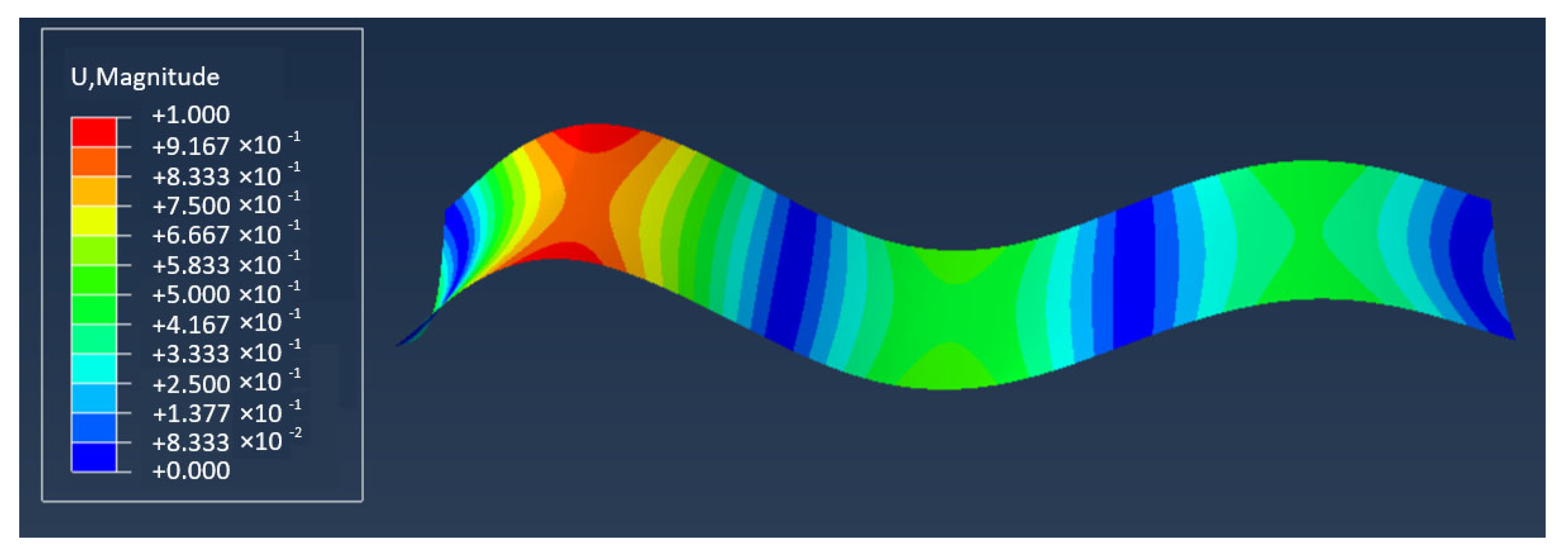
Figure 2 illustrates the critical instability analysis of CSP simulated using FEA. By using FEA, detailed information regarding the displacement field and instability modes of CSP can be obtained. Figure 2 displays the distribution of the displacement field, indicating the magnitude of displacement at each point in the simulation results, along with the manifestation of the instability mode. Indeed, these visualizations are crucial for intuitively understanding how CSP deforms under stress or loading conditions. They enable us to assess structural safety by visually inspecting how the material behaves under different scenarios, identifying potential areas of concern or improvement in design. By conducting further analysis of the displacement field and the magnitude of displacement, we can identify various forms of instability, such as concentration of displacement, diffusion of displacement, or abnormal growth patterns. These findings serve as valuable guidance and a basis for optimizing the design to ensure structural integrity and performance under varying conditions.
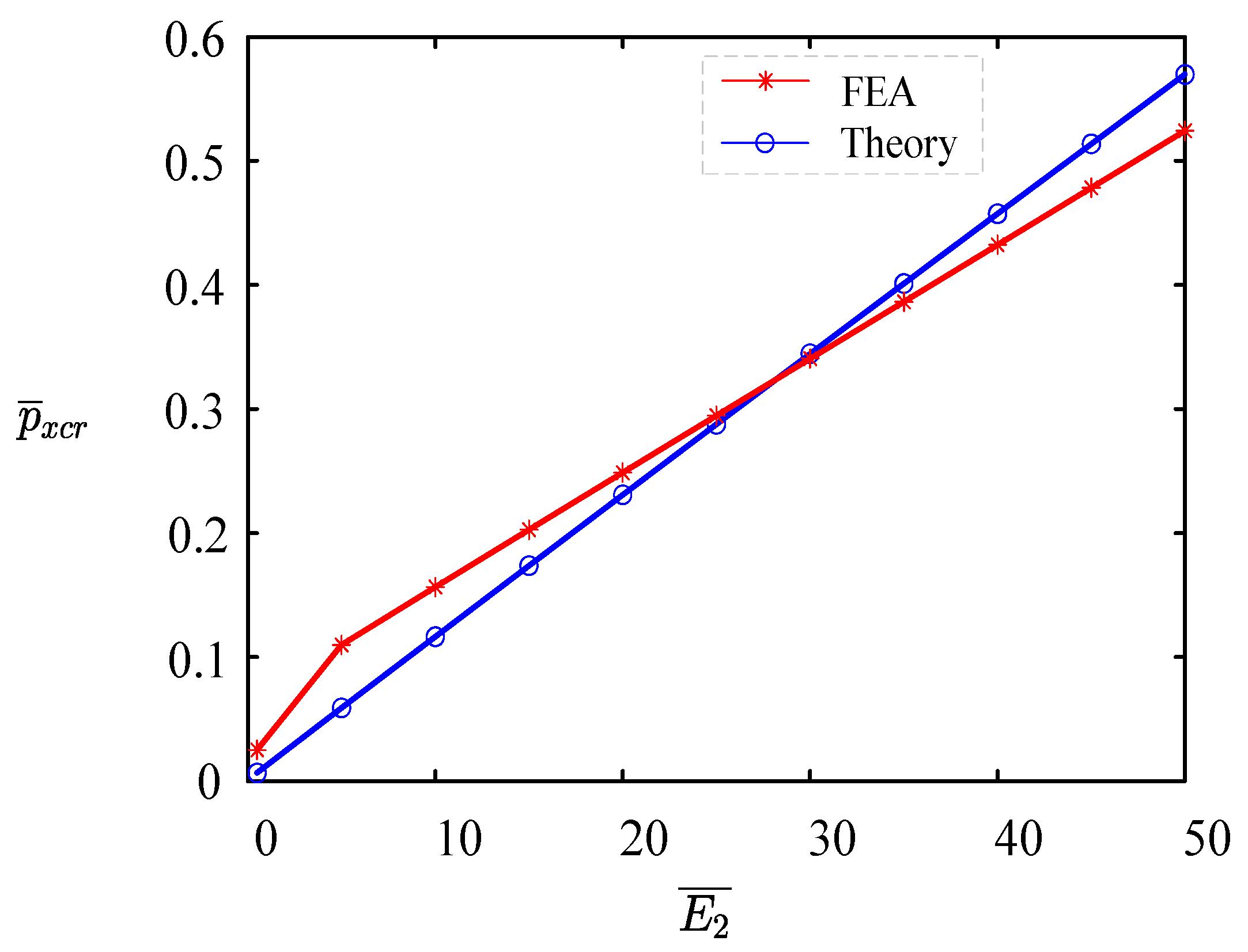
Figure 3 compares the numerical simulation using FEA with the theoretical derivation of the critical buckling load of plates based on the elastic modulus. It is evident from the figure that there is a high consistency between the numerical curve obtained from theoretical solutions and the results from FEA. This high degree of agreement between the theoretical calculation and FEA results strongly verifies the calculation method for determining the stability of sandwich CSP pipe-arches. At the same time, the root mean square error [53,54,55] is 0.1246, and the average error rate [56] is 6.8% when comparing the FEA with the theoretical calculation. These error indices indicate high agreement between the simulation results and the theoretical predictions, thereby confirming the accuracy and reliability of the adopted calculation method.

4. Bucking Behaviors

From Equations (20), (22), (23), (30), (32), and (33), it can seen that the key factors affecting the buckling stability of CSP composite structures include b ¯ , E ¯ 2 , t ¯ 1 , t ¯ 2 , v , and J ζ ¯ . In this section, we will delve into the specific impacts of the aforementioned influencing parameters on the buckling stability of the CSP composite structure. We aim to illustrate how these parameters affect the critical buckling load and critical wavenumber, providing valuable insights for practical engineering applications.

4.1. Effect of the Length of Straight Segment

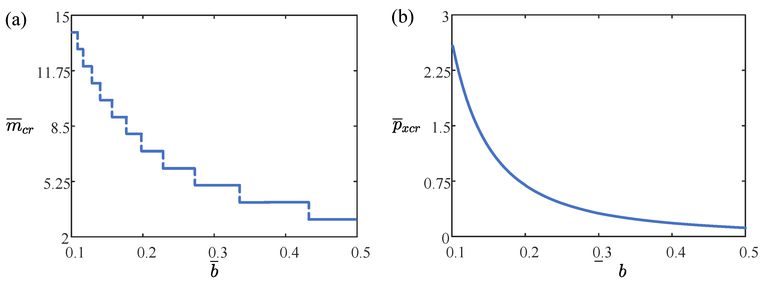
Figure 4 illustrates the impact of the dimensionless length b ¯ on the critical wavenumber m ¯ c r and the critical buckling load p ¯ x c r . The dimensionless parameters used here are E ¯ 1 = 10, E ¯ 2 = 43, t ¯ 1 = 0.03, t ¯ 2 = 0.012, v ¯ = 0.3, and J ζ ¯ = 0.5. From Figure 4a, it can be seen that the critical wavenumber decreases step by step with the increase of the length b ¯ , and Figure 4b also shows that the critical buckling load p ¯ x c r decreases gradually with the increase of the dimensionless length b ¯ . The above results are due to the depth of the corrugations in the steel increasing with the length of the straight segment, making the CSP more prone to destabilization, which leads to a decrease in the number of waves as shown in Figure 4a. Conversely, a relatively shorter length b ¯ enhances the stability of the CSP, resulting in a relatively high critical wavenumber and critical buckling load under destabilization conditions. Therefore, selecting a relatively shorter length of the straight segment can enhance stability in engineering applications.

4.2. Effect of the Thickness of Core Layer

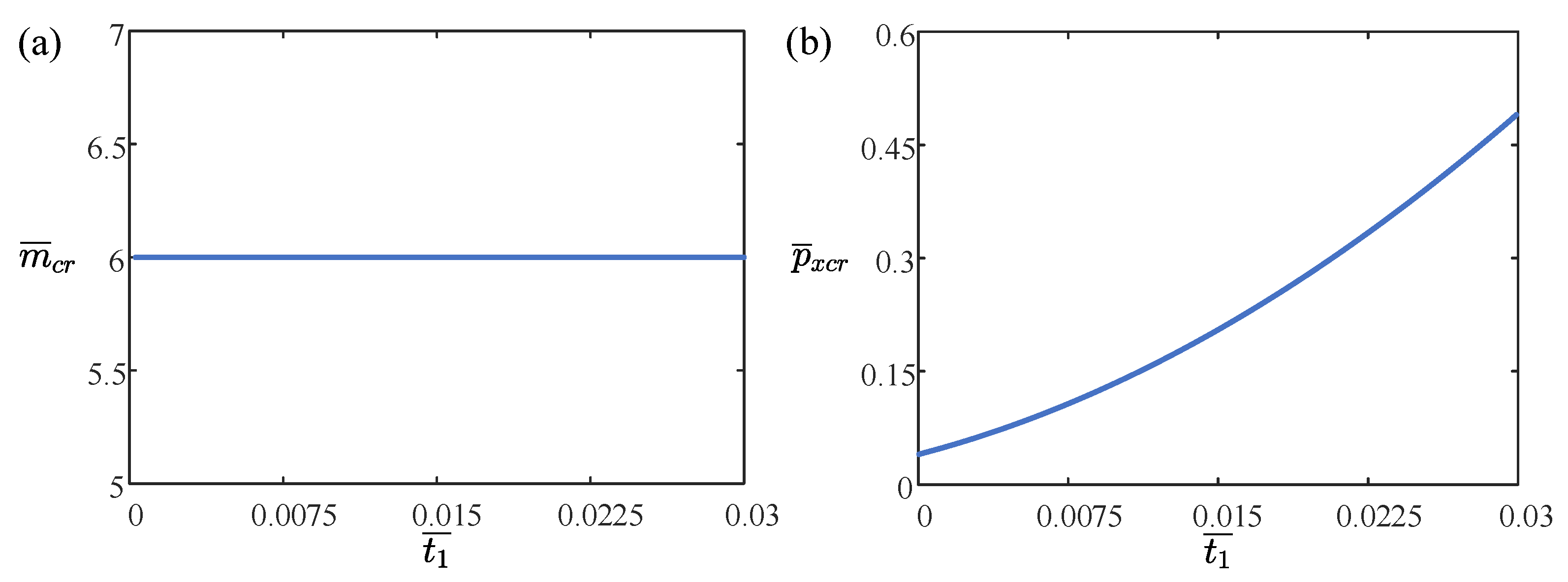
Figure 5 illustrates the impact of the dimensionless core thickness t ¯ 1 on the dimensionless critical wavenumber m ¯ c r and the dimensionless critical buckling load p ¯ x c r . The dimensionless parameters used here are E ¯ 1 = 10, E ¯ 2 = 43, b ¯ = 0.24, t ¯ 2 = 0.012, v ¯ = 0.3, and J ζ ¯ = 0.5. From Figure 5a, it can be seen that the dimensionless critical wavenumber m ¯ c r does not increase with an increase in the dimensionless core thickness t ¯ 1 . Figure 5b also shows that the dimensionless critical buckling load p ¯ x c r increases gradually with increasing dimensionless core thickness t ¯ 1 . These results are due to the increased strength of the sandwich CSP pipe-arch with an increase in the core thickness. This requirement for a larger critical load prevents the destabilization of CSP, thereby enhancing the stability of the CSP composite slab, as shown in Figure 5a. However, it has no significant effect on the number of critical destabilization waves, as seen in Figure 5b. Therefore, increasing the thickness of the CSP layer can significantly enhance the critical load of the structure. This means that a greater load is required to cause instability, thereby improving the structure’s overall stability and resilience against external pressures. By boosting the critical load, the structure becomes more robust and less susceptible to failure from load variations and other external factors.

4.3. Effect of the Thickness of CSP Layer

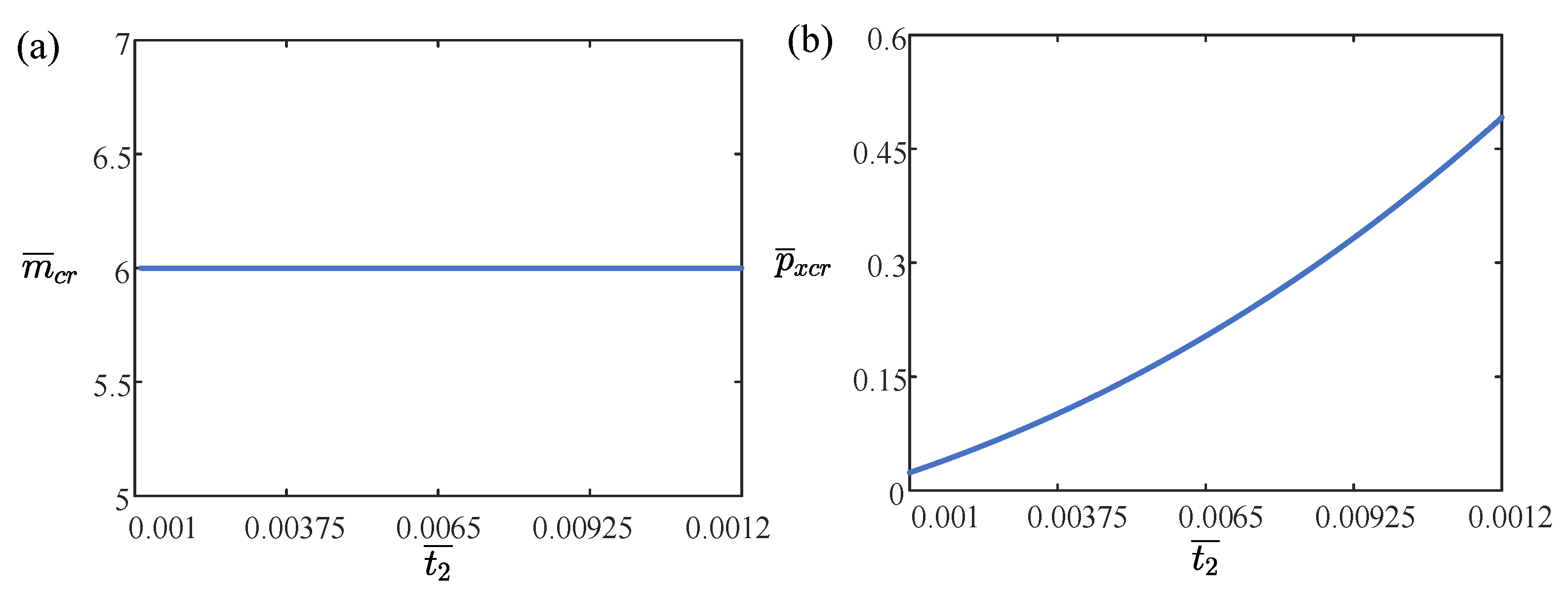
Figure 6 illustrates the impact of the dimensionless CSP t ¯ 2 on the dimensionless critical wave umber m ¯ c r and the critical buckling load p ¯ x c r . The dimensionless parameters used here are E ¯ 1 = 10, E ¯ 2 = 43, b ¯ = 0.24, t ¯ 1 = 0.03, v ¯ = 0.3, and J ζ ¯ = 0.5. From Figure 6a, it is also apparent that the increase of dimensionless CSP thickness t ¯ 2 does not affect dimensionless critical wavenumber m ¯ c r . From Figure 6b, it also manifests that dimensionless critical buckling load p ¯ x c r gradually increases with the increase of dimensionless CSP thickness t ¯ 2 . These results are due to the strength of the sandwich CSP pipe-arch increasing with the thickness of CSP, which requires a larger critical load for the destabilization of the sandwich CSP pipe-arch. Therefore, the thickness of CSP can be increased to obtain better stability in engineering applications.

4.4. Effect of the Elastic Modulus of CSP

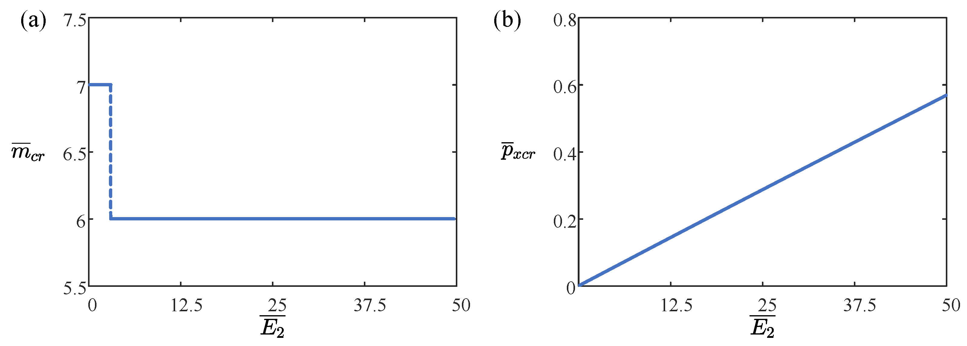
Figure 7 illustrates the impact of the dimensionless CSP elastic modulus E ¯ 2 on the dimensionless critical wavenumber m ¯ c r and the critical buckling load p ¯ x c r . The dimensionless parameters used here are E ¯ 1 = 10, E ¯ 2 = 43, b ¯ = 0.24, t ¯ 1 = 0.03, v ¯ = 0.3, and J ζ ¯ = 0.5. From Figure 7a, it can be seen that the dimensionless critical wavenumber m ¯ c r decreases and then remains constant within a certain range as the modulus of elasticity E ¯ 2 of the CSP increases. From Figure 7b, it can be similarly concluded that the critical buckling load p ¯ x c r gradually increases as the CSP elastic modulus E ¯ 2 increases. The strength of the sandwich CSP pipe-arch increases as the modulus of elasticity of the sandwich CSP pipe-arch increases, requiring a larger critical load for its destabilization. Therefore, the thickness of CSP can be increased to obtain better stability in engineering applications.

4.5. Effect of Poisson’s Ratio

Figure 8 illustrates the impact of Poisson’s ratio v ¯ on the critical wavenumber m ¯ c r and the critical buckling load p ¯ x c r . The dimensionless parameters used here are E ¯ 1 = 10, E ¯ 2 = 43, b ¯ = 0.24, t ¯ 1 = 0.03, t ¯ 2 = 0.012, and J ζ ¯ = 0.5. From Figure 8a, it can be seen that the increase of Poisson’s ratio does not affect the critical bending wavenumber of CSP. Figure 8b shows that, over a wide range of Poisson’s ratio values v ¯ for sandwich CSP pipe-arch, the critical buckling load p ¯ x c r initially increases slowly, accelerates gradually, and eventually exhibits a sharp rise. The strength of the sandwich CSP pipe-arch increases as the Poisson’s ratio of the sandwich CSP pipe-arch increases, requiring a larger critical load for its destabilization. Therefore, the Poisson’s ratio of sandwich CSP pipe-arches can be increased to obtain better stability in engineering applications.

4.6. Effect of the Rotational Constraint Stiffness

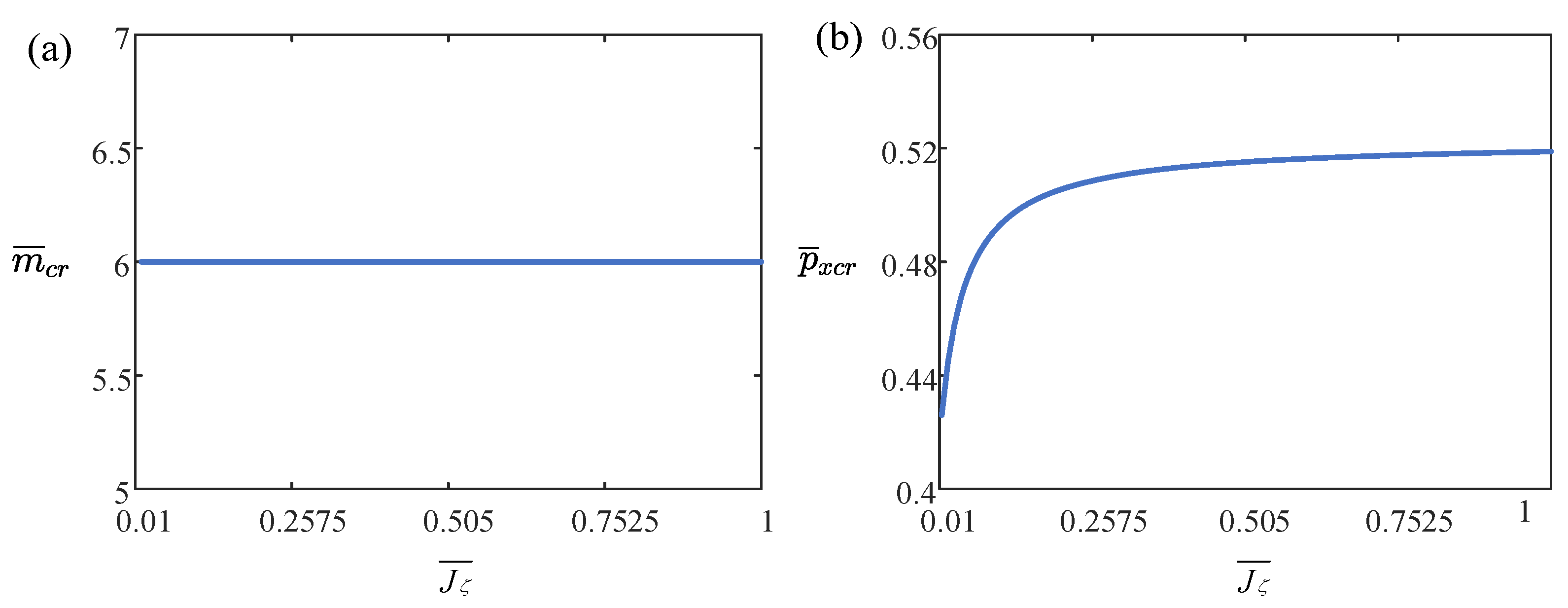
Figure 9 illustrates the impact of the dimensionless rotational constraint stiffness J ζ ¯ on the dimensionless critical wavenumber m ¯ c r and the dimensionless critical buckling load p ¯ x c r . The dimensionless parameters used here are E ¯ 1 = 10, E ¯ 2 = 43, b ¯ = 0.24, t ¯ 1 = 0.03, t ¯ 2 = 0.012, and v ¯ = 0.3. From Figure 9a, it is evident that the dimensionless critical wavenumber m ¯ c r remains unchanged as the dimensionless rotational constrained stiffness J ζ ¯ of the sandwich CSP pipe-arch increases. Figure 9b indicates a significant increase in the dimensionless critical buckling load p ¯ x c r within a certain range of the dimensionless rotational constrained stiffness J ζ ¯ of the sandwich CSP pipe-arch. The dimensionless critical buckling load p ¯ x c r shows a slower rise as the dimensionless rotational constrained stiffness J ζ ¯ of the sandwich CSP pipe-arch increases, with the growth rate gradually diminishing until it stabilizes. The strength of the sandwich CSP pipe-arch increases as the rotational constrained stiffness of the sandwich CSP pipe-arch increases, requiring a larger critical load for its destabilization. Therefore, the rotational constrained stiffness of sandwich CSP pipe-arches can be increased to obtain better stability in engineering applications.

5. Conclusions

In this paper, we examined the buckling stability of straight segments of sandwich CSP pipe-arches in underground spaces. The sandwich CSP pipe-arch theoretical mechanical model is established by combining the elastic stability theory and Hoff sandwich plate theory, and the theoretical expression of elastic buckling of the straight segment of the sandwich CSP pipe-arch is obtained. Through theoretical derivation and numerical simulation, elastic buckling analysis of sandwich CSP pipe-arches under pressure is conducted in this paper. Based on these insights, we have drawn the following conclusions:
  • This study employs Hoff sandwich plate theory and the Rayleigh–Ritz method to establish a theoretical model for analyzing the buckling stability of sandwich CSP pipe-arches in underground spaces. Through this approach, we have derived analytical formulas to compute the critical load and wavenumber, offering comprehensive insights into their buckling behavior.
  • This study explores the factors influencing the elastic buckling of sandwich CSP pipe-arches. The results indicate that increasing the span side length decreases the load-bearing capacity, while increasing core thickness, CSP thickness, CSP elastic modulus, Poisson’s ratio, and rotational constraint stiffness enhances the load-bearing capacity.
  • This study investigates how various factors affect the wavenumber of sandwich CSP pipe-arches. The analysis reveals that increasing the span side length decreases the wavenumber. Core thickness and CSP thickness do not significantly affect the wavenumber when increased. Conversely, increasing the CSP elastic modulus reduces the wavenumber. Changes in Poisson’s ratio and rotational constraint stiffness do not notably alter the wavenumber when increased.
  • Through analysis of buckling stability, we can refine structural design to enhance safety and reliability. This approach not only contributes to the structural design of CSP composite structures but also ensures the dependability of engineering projects. For instance, in applications involving sandwich CSP pipe-arches, augmenting the thickness of CSP enhances structural stability. This ensures optimal material utilization and maximizes cost-effectiveness.
Additionally, simplifications in our study may impact the applicability of our findings to real-world scenarios. Therefore, it is essential to conduct future experimental validations to refine and confirm our results, thereby bridging the gap between theoretical analysis and practical application.

Author Contributions

Conceptualization, K.L.; methodology, C.C.; software, Z.S.; validation, P.X.; investigation, C.C. and Z.S.; data curation, F.S., P.X. and J.L.; writing—original draft preparation, C.C.; writing—review and editing, K.L. and Z.S.; supervision, K.L. All authors have read and agreed to the published version of the manuscript.

Funding

This study is supported by University Natural Science Research Project of Anhui Province (Nos. 2022AH030035 and 2022AH020029), National Natural Science Foundation of China (Grant No. 12172001), Anhui Provincial Natural Science Foundation (No. 2208085Y01), Outstanding Talents Cultivation Project of Universities in An-hui (No. gxyg2022029), and Research Project of China First Highway Engineering Co., Ltd. (T-GL-ZCBGS(J)-ANH-HZ-02-JS-032).

Data Availability Statement

The data presented in this study are available on request from the corresponding author.

Conflicts of Interest

Author Chengwen Che, Zhanying Sun and Kai Li was employed by the company China First Highway Engineering Co. The remaining authors declare that the research was conducted in the absence of any commercial or financial relationships that could be construed as a potential conflict of interest. The authors declare that they have no known competing financial interests or personal relationships that could have appeared to influence the work reported in this paper. Chengwen Che, Zhanying Sun and Kai Li are employee of China First Highway Engineering Co, who provided funding and teachnical support for the work. The funder had no role in the design of the study; in the collection, analysis, or interpretation of data, in the writing of the manuscript, or in the decision to publish the results.

References

  1. Mahoutian, M.; Shekarchi, M.; Libre, N.A. Application of Steel Fiber Reinforced Lightweight Aggregate Concrete in Underground Mining. J. Min. Sci. 2011, 47, 606–617. [Google Scholar] [CrossRef]
  2. Machelski, C.; Michalski, J.B.; Janusz, L. Deformation Factors of Buried Corrugated Structures. Transp. Res. Rec. J. Transp. Res. Board 2009, 2116, 70–75. [Google Scholar] [CrossRef]
  3. Hassanein, M.F.; Kharoob, O.F. Behavior of Bridge Girders with Corrugated Webs: (II) Shear Strength and Design. Eng. Struct. 2013, 57, 544–553. [Google Scholar] [CrossRef]
  4. Kanchanadevi, A.; Ramanjaneyulu, K.; Gandhi, P. Shear Resistance of Embedded Connection of Composite Girder with Corrugated Steel Web. J. Constr. Steel Res. 2021, 187, 106994. [Google Scholar] [CrossRef]
  5. Kumar, M.; Goel, M.D.; Matsagar, V.A.; Rao, K.S. Response of Semi-Buried Structures Subjected to Multiple Blast Loading Considering Soil–Structure Interaction. Indian Geotech. J. 2015, 45, 243–253. [Google Scholar] [CrossRef]
  6. Kang, J.; Parker, F.; Yoo, C.H. Soil–Structure Interaction for Deeply Buried Corrugated Steel Pipes Part I: Embankment Installation. Eng. Struct. 2008, 30, 384–392. [Google Scholar] [CrossRef]
  7. Sun, H.-J.; Guo, Y.-L.; Wen, C.-B.; Zuo, J.-Q.; Zhao, Q.; Liu, Z.-G. The Strength Design of Deeply Buried Circular Corrugated Steel Arches with Considering Only Soil Radial Restraining. Thin-Walled Struct. 2023, 183, 110422. [Google Scholar] [CrossRef]
  8. Han, B.; Zhang, Z.-J.; Zhang, Q.-C.; Zhang, Q.; Lu, T.J.; Lu, B.-H. Recent advances in hybrid lattice-cored sandwiches for enhanced multifunctional performance. Extreme Mech. Lett. 2017, 10, 58–69. [Google Scholar] [CrossRef]
  9. Milovanović, B.; Banjad Pečur, I. Review of Active IR Thermography for Detection and Characterization of Defects in Reinforced Concrete. J. Imaging 2016, 2, 11. [Google Scholar] [CrossRef]
  10. Concu, G.; Trulli, N. Concrete Defects Sizing by Means of Ultrasonic Velocity Maps. Buildings 2018, 8, 176. [Google Scholar] [CrossRef]
  11. Sohn, H.-G.; Lim, Y.-M.; Yun, K.-H.; Kim, G.-H. Monitoring Crack Changes in Concrete Structures. Comput.-Aided Civ. Infrastruct. Eng. 2005, 20, 52–61. [Google Scholar] [CrossRef]
  12. Fujita, Y.; Mitani, Y.; Hamamoto, Y. A Method for Crack Detection on a Concrete Structure. In Proceedings of the 18th International Conference on Pattern Recognition (ICPR’06), Hong Kong, China, 20–24 August 2006; pp. 901–904. [Google Scholar] [CrossRef]
  13. Wang, T.; Tan, L.; Xie, S.; Ma, B. Development and Applications of Common Utility Tunnels in China. Tunn. Undergr. Space Technol. 2018, 76, 92–106. [Google Scholar] [CrossRef]
  14. Rauch, A.F.; Sargand, S.M.; Hazen, G.A. Behavior of Deeply Corrugated Steel Plate in Culvert. J. Struct. Eng. 1994, 120, 1651–1655. [Google Scholar] [CrossRef]
  15. Sargand, S.M.; Khoury, I.; Hussein, H.H.; Masada, T. Load Capacity of Corrugated Steel Pipe with Extreme Corrosion under Shallow Cover. J. Perform. Constr. Facil. 2018, 32, 04018050. [Google Scholar] [CrossRef]
  16. Kells, J.A. Hydraulic Performance of Damaged-End Corrugated Steel Pipe Culverts. Can. J. Civ. Eng. 2008, 35, 918–924. [Google Scholar] [CrossRef]
  17. Katona, M.G. Influence of Soil Models on Structural Performance of Buried Culverts. Int. J. Geomech. 2017, 17, 04016031. [Google Scholar] [CrossRef]
  18. Bian, X.; Tang, X.; Shen, W.; Ling, D.; Chen, Y. An Experimental Study on a Culvert Buried in Granular Soil Subjected to Vehicle Loads. Adv. Struct. Eng. 2012, 15, 1031–1040. [Google Scholar] [CrossRef]
  19. Arockiasamy, M.; Chaallal, O.; Limpeteeprakarn, T. Full-Scale Field Tests on Flexible Pipes Under Live Load Application. J. Perform. Constr. Facil. 2006, 20, 21–27. [Google Scholar] [CrossRef]
  20. Yu, S.; Wu, H.; Zhang, G.; Wang, Z.; Yao, J.; Li, H.; Liu, C. Experimental Study on Anti-Shallow-Buried-Explosion Capacity of a Corrugated Steel-Plain Concrete Composite Structure. Int. J. Impact Eng. 2023, 172, 104393. [Google Scholar] [CrossRef]
  21. Zhang, J.-L.; Liu, B.-D.; Liu, R. Behavior of Sinusoidal-Corrugated-Steel-Plate–Concrete Composite Slabs: Experimental Investigation and Theoretical Model Development. J. Constr. Steel Res. 2021, 187, 106958. [Google Scholar] [CrossRef]
  22. Machimdamrong, C.; Watanabe, E.; Utsunomiya, T. Analysis of Corrugated Steel Web Girders by an Efficient Beam Bending Theory. Struct. Eng./Earthq. Eng. 2004, 21, 131S–142S. [Google Scholar] [CrossRef]
  23. Jia, Z.; Stewart, G.W. An Analysis of the Rayleigh–Ritz Method for Approximating Eigenspaces. Math. Comput. 2001, 70, 637–647. [Google Scholar] [CrossRef]
  24. Yserentant, H. A Short Theory of the Rayleigh–Ritz Method. Comput. Methods Appl. Math. 2013, 13, 495–502. [Google Scholar] [CrossRef]
  25. Chen, T.; Su, M.; Pan, C.; Zhang, L.; Wang, H. Local Buckling of Corrugated Steel Plates in Buried Structures. Thin-Walled Struct. 2019, 144, 106348. [Google Scholar] [CrossRef]
  26. Beben, D. Field Performance of Corrugated Steel Plate Road Culvert under Normal Live-Load Conditions. J. Perform. Constr. Facil. 2013, 27, 807–817. [Google Scholar] [CrossRef]
  27. Driver, R.G.; Abbas, H.H.; Sause, R. Shear Behavior of Corrugated Web Bridge Girders. J. Struct. Eng. 2006, 132, 195–203. [Google Scholar] [CrossRef]
  28. Cheng, Y.; Su, X.; Zhou, M.; Zhang, J. Shear Performance of Tapered Box Girders with Corrugated Steel Webs in Extradosed Cable-Stayed Bridges Under Cable Forces. Eng. Struct. 2024, 310, 118107. [Google Scholar] [CrossRef]
  29. Ke, L.; Liu, K.; Wu, G.; Wang, Z.; Wang, P. Multi-Objective Optimization Design of Corrugated Steel Sandwich Panel for Impact Resistance. Metals 2021, 11, 1378. [Google Scholar] [CrossRef]
  30. Waqas, H.A.; Waseem, M.; Riaz, A.; Ilyas, M.; Naveed, M.; Seitz, H. Influence of Haunch Geometry and Additional Steel Reinforcement on Load Carrying Capacity of Reinforced Concrete Box Culvert. Materials 2023, 16, 1409. [Google Scholar] [CrossRef]
  31. Ding, W.; Huang, X.; Li, S.; Liu, W.; Zhang, Q. Flexural Stiffness Characterization of the Corrugated Steel–Concrete Composite Structure for Tunnel Projects. Undergr. Space 2023, 12, 18–30. [Google Scholar] [CrossRef]
  32. Emami, F.; Mofid, M.; Vafai, A. Experimental Study on Cyclic Behavior of Trapezoidally Corrugated Steel Shear Walls. Eng. Struct. 2013, 48, 750–762. [Google Scholar] [CrossRef]
  33. Lin, X.; Far, H. Post-buckling Strength of Welded Steel I-Girders with Corrugated Webs. Int. J. Steel Struct. 2021, 21, 850–860. [Google Scholar] [CrossRef]
  34. Cheng, Z.Q.; Wang, X.X.; Huang, M.G. Large Deflections of Rectangular Hoff Sandwich Plates. Int. J. Solids Struct. 1993, 30, 2335–2346. [Google Scholar] [CrossRef]
  35. Qiu, X.; Deshpande, V.S.; Fleck, N.A. Dynamic Response of a Clamped Circular Sandwich Plate Subject to Shock Loading. J. Appl. Mech. 2004, 71, 637–645. [Google Scholar] [CrossRef]
  36. Cai, J.; Long, Y.-L. Local buckling of steel plates in rectangular CFT columns with binding bars. J. Constr. Steel Res. 2009, 65, 965–972. [Google Scholar] [CrossRef]
  37. Abbas, H.H.; Sause, R.; Driver, R.G. Analysis of Flange Transverse Bending of Corrugated Web I-Girders under In-Plane Loads. J. Struct. Eng. 2007, 133, 347–355. [Google Scholar] [CrossRef]
  38. Oiwa, M.; Ogasawara, T.; Yoshinaga, H.; Oguri, T.; Aoki, T. Numerical Analysis of Face Sheet Buckling for a CFRP/Nomex Honeycomb Sandwich Panel Subjected to Bending Loading. Compos. Struct. 2021, 270, 114037. [Google Scholar] [CrossRef]
  39. Ostrosablin, N.I. Compatibility Conditions of Small Deformations and Stress Functions. J. Appl. Mech. Tech. Phys. 1997, 38, 774–783. [Google Scholar] [CrossRef]
  40. Patnaik, S.N.; Satish, H.G. Analysis of Continuum Using Boundary Compatibility Conditions of Integrated Force Method. Comput. Struct. 1990, 34, 287–295. [Google Scholar] [CrossRef]
  41. Sun, J.; Yu, T.; Dong, P. Evaluation of 3D Slope Stability Based on the Minimum Potential Energy Principle. Comput. Geotech. 2022, 146, 104717. [Google Scholar] [CrossRef]
  42. Ben-Abu, Y.; Eshach, H.; Yizhaq, H. Interweaving the Principle of Least Potential Energy in School and Introductory University Physics Courses. Symmetry 2017, 9, 45. [Google Scholar] [CrossRef]
  43. Rao, K.P.; Sivaram, K. A Review of Ring-Compression Testing and Applicability of the Calibration Curves. J. Mater. Process. Technol. 1993, 37, 295–318. [Google Scholar] [CrossRef]
  44. Zhang, X.; Chen, K.; Lu, X.; Xu, G.; Chen, T. Constructional Behavior of Multi-Span Corrugated Steel Arch Culverts Stiffened by Concrete Rings. J. Constr. Steel Res. 2024, 218, 108751. [Google Scholar] [CrossRef]
  45. Ruzicka, M.C. On Dimensionless Numbers. Chem. Eng. Res. Des. 2008, 86, 835–868. [Google Scholar] [CrossRef]
  46. Tang, G.; Yin, L.; Guo, X.; Cui, J. Finite Element Analysis and Experimental Research on Mechanical Performance of Bolt Connections of Corrugated Steel Plates. Int. J. Steel Struct. 2015, 15, 193–204. [Google Scholar] [CrossRef]
  47. Chung, K.F.; Ip, K.H. Finite Element Investigation on the Structural Behaviour of Cold-Formed Steel Bolted Connections. Eng. Struct. 2001, 23, 1115–1125. [Google Scholar] [CrossRef]
  48. Chan, C.L.; Khalid, Y.A.; Sahari, B.B.; Hamouda, A.M.S. Finite Element Analysis of Corrugated Web Beams Under Bending. J. Constr. Steel Res. 2002, 58, 1391–1406. [Google Scholar] [CrossRef]
  49. Degtyarev, V.V. Concentrated Load Distribution in Corrugated Steel Decks: A Parametric Finite Element Study. Eng. Struct. 2020, 206, 110158. [Google Scholar] [CrossRef]
  50. John, K.; Ashraf, M.; Weiss, M.; Al-Ameri, R. Experimental and Finite Element Study of a Novel Two-Way Corrugated Steel Deck System for Composite Slabs. J. Compos. Sci. 2022, 6, 261. [Google Scholar] [CrossRef]
  51. Numayr, K.S.; Haddad, R.H. Analytical Solution of Buckling of Beams with Two Delaminations. Mech. Compos. Mater. Struct. 2001, 8, 283–297. [Google Scholar] [CrossRef]
  52. Erdal, F.; Tunca, O.; Tas, S.; Ozcelik, R. Experimental and Finite Element Study of Optimal Designed Steel Corrugated Web Beams. Adv. Struct. Eng. 2021, 24, 1814–1827. [Google Scholar] [CrossRef]
  53. Karunasingha, D.S.K. Root Mean Square Error or Mean Absolute Error? Use Their Ratio as Well. Inf. Sci. 2022, 585, 609–629. [Google Scholar] [CrossRef]
  54. Willmott, C.J.; Matsuura, K. Advantages of the Mean Absolute Error (MAE) Over the Root Mean Square Error (RMSE) in Assessing Average Model Performance. Clim. Res. 2005, 30, 79–82. [Google Scholar] [CrossRef]
  55. Grätsch, T.; Bathe, K.-J. A Posteriori Error Estimation Techniques in Practical Finite Element Analysis. Comput. Struct. 2005, 83, 235–265. [Google Scholar] [CrossRef]
  56. Antos, A.; Devroye, L.; Gyorfi, L. Lower Bounds for Bayes Error Estimation. IEEE Trans. Pattern Anal. Mach. Intell. 1999, 21, 643–645. [Google Scholar] [CrossRef]
Figure 1. Diagram of a sandwich CSP pipe-arch. (a) Schematic of a sandwich CSP pipe-arch. (b) Cross-section of a sandwich CSP pipe. (c) Equivalent stress distribution diagram of the straight segment. (d) Diagram of cross section of the straight segment. The sandwich CSP pipe-arch embedded in the soil consists of a core layer and two CSP layers, featuring both corrugated and straight segments. The simplified mechanics model for the straight segment of the sandwich CSP pipe-arch experiences uniform loading on the short side and torsional loading on the long side. The soil constraint beneath is simplified to a series of spring constraints operating solely under compression.
Buildings 14 02696 g001
Figure 2. Displacement field U of the buckled CSP by FEA simulation.
Buildings 14 02696 g002
Figure 3. Comparison of critical buckling loads obtained from theoretical solutions and finite element analysis. The theoretical results align with the numerical simulation.
Buildings 14 02696 g003
Figure 4. Effect of dimensionless length b ¯ on dimensionless critical buckling load p ¯ x c r and dimensionless critical wavenumber m ¯ c r . (a) Dimensionless critical wavenumber m ¯ c r . (b) Dimensionless critical buckling load p ¯ x c r . As the dimensionless short side length increases, the dimensionless critical buckling load decreases, initially at a faster rate, then slows down gradually towards stabilization.
Buildings 14 02696 g004
Figure 5. Effect of dimensionless core thickness t ¯ 1 on dimensionless critical wavenumber m ¯ c r and the dimensionless critical buckling load p ¯ x c r . (a) Dimensionless critical wavenumber m ¯ c r . (b) Dimensionless critical buckling load p ¯ x c r . As the dimensionless core thickness increases, the rate of increase for the dimensionless critical buckling load gradually slows down.
Buildings 14 02696 g005
Figure 6. Effect of dimensionless CSP thickness t ¯ 2 on dimensionless critical wavenumber m ¯ c r and the dimensionless critical buckling load p ¯ x c r . (a) Dimensionless critical wavenumber m ¯ c r . (b) Dimensionless critical buckling load p ¯ x c r . As the dimensionless CSP thickness increases, the rate of increase for the dimensionless critical buckling load gradually slows down.
Buildings 14 02696 g006
Figure 7. Effect of the dimensionless CSP elastic modulus E ¯ 2 on dimensionless critical wavenumber m ¯ c r and the dimensionless critical buckling load p ¯ x c r . (a) Dimensionless critical wavenumber m ¯ c r . (b) Dimensionless critical buckling load p ¯ x c r . As the dimensionless CSP elastic modulus increases, the dimensionless critical buckling load grows steadily at a constant rate.
Buildings 14 02696 g007
Figure 8. Effect of Poisson’s ratio v ¯ on dimensionless critical wavenumber m ¯ c r and the dimensionless critical buckling load p ¯ x c r . (a) Dimensionless critical wavenumber m ¯ c r . (b) Dimensionless critical buckling load p ¯ x c r . As the Poisson’s ratio increases, the dimensionless critical buckling load initially grows at a slower pace, subsequently accelerates gradually.
Buildings 14 02696 g008
Figure 9. Effect of the dimensionless rotational constraint stiffness J ζ ¯ on dimensionless critical wavenumber m ¯ c r and the dimensionless critical buckling load p ¯ x c r . (a) Dimensionless critical wavenumber m ¯ c r . (b) Dimensionless critical buckling load p ¯ x c r . As the dimensionless rotational constraint stiffness increases, the dimensionless critical buckling load initially rises at a faster rate before gradually leveling off and stabilizing.
Buildings 14 02696 g009
Table 1. Material properties and geometric parameters.
ParameterDefinitionValueUnit
a Span of the CSP pipe-arch3 × 102~5 × 102mm
b Length of the straight segment30~60mm
t ¯ 1 Thickness of core layer1~3mm
t ¯ 2 Thickness of single CSP layer0.4~1.2mm
E 1 Elastic modulus of core layer1.0 × 104~5.0 × 10⁶N/m2
E 2 Elastic modulus of CSP layer2.0 × 1011~2.1 × 10¹¹N/m2
v Poisson’s ratio2.0 × 106~2.0 × 10⁶/
J ζ Rotational constraint stiffness10~9.9 × 10³N/rad
k Soil compression stiffness1.4 × 107~6.5 × 10⁷N/m3
Table 2. Dimensionless parameters.
Parameter b ¯ E ¯ 1 E ¯ 2 t ¯ 1 t ¯ 2 v ¯ J ζ ¯
Value0.1–0.50.1–500.1–500.001–0.030.001–0.0120.01–10.01–1
Disclaimer/Publisher’s Note: The statements, opinions and data contained in all publications are solely those of the individual author(s) and contributor(s) and not of MDPI and/or the editor(s). MDPI and/or the editor(s) disclaim responsibility for any injury to people or property resulting from any ideas, methods, instructions or products referred to in the content.