Article

Optimizing Grouting Parameters to Control Ground Deformation in the Shield Tunneling

1
College of Mining Engineering, Taiyuan University of Technology, Taiyuan 030024, China
2
School of Transportation, Southeast University, Nanjing 211189, China
*
Author to whom correspondence should be addressed.
Buildings 2024, 14(9), 2799; https://doi.org/10.3390/buildings14092799
Submission received: 12 August 2024 / Revised: 25 August 2024 / Accepted: 3 September 2024 / Published: 5 September 2024

Abstract

:
In urban shield tunneling, reducing the disturbance of underground construction to the surrounding environment is important for both tunnel engineers and researchers. Among other factors, the quality of synchronous grouting is one of the crucial factors affecting the safe construction of shields. In order to determine a reasonable grouting pressure and grout amount during shield construction, the relationships among synchronous grouting pressure, grout amount and shield chamber pressure are analyzed using field monitoring data. Based on the tunnel face pressure and the ultimate yield conditions of the soil at the gap edge, a method for calculating the grouting pressure considering the overburdening load of the tunnel was proposed. Then, by linking the grout amount and the grouting pressure, an accurate calculation method for the simultaneous grout amount in shield construction was proposed. These methods were then used in the construction of the Jurong shield tunnel. The results show that the adopted grouting pressure and grout amount calculated by the proposed method, which considered the change of the overburdening load of the tunnel, can well control the ground deformation caused by the shield construction and significantly reduce the uneven settlement of the surface buildings. The proposed methods in this paper may provide a reference for other shield construction projects.

1. Introduction

With the development and utilization of urban underground space, shield construction technology is widely used in urban metro tunnels and municipal tunnels due to its low impact on the surrounding environment. The construction of a metro shield can have a large impact on adjacent buildings. In particular, old residential buildings are built on strip compacted foundations, which are highly susceptible to accidents such as wall cracking and tilting due to uneven settlement of the foundations during the shield construction process. Xu [1,2] studied the effect of tunnels on different types of building structures through centrifuge model tests and concluded that a larger building aspect ratio would increase the deformation of the building, whereas increasing the stiffness ratio of the building would reduce the effect of the tunnel on the building. Therefore, brick and concrete buildings with strip foundations, greater building weights and larger transverse sections are less able to resist ground deformation [3,4]. As the excavation diameter of the shield machine cutter is larger than the outer diameter of the pipe segment, a gap is created between the shield tail and the segment, and the size of the shield tail gap is usually between 8 cm and 16 cm [5]. The shield tail gap leaves the soil in an unsupported state, resulting in the settlement of the ground and surface buildings/structures and sometimes causing tunnel deflection [6,7]. In practice, post-wall grouting is often used to fill the gap at the shield tail. The compression characteristics of the grouting material and the grout amount affect the deformation of the soil around the tunnel [8]. For instance, during the shield tunnelling of Nanjing metro line 3 and Shenzhen metro line 5, the unreasonable setting of grouting parameters resulted in a large settlement of the nearby buildings and road surfaces, causing wall cracks and uneven settlement of road surfaces [9,10]. Figure 1 shows a photograph of the house cracking caused by the shield tunnel. Therefore, the proper application of post-wall grouting technology in the construction of shield tunnels has become a common concern for tunnel designers and engineers needing to control the ground settlement and tunnel uplift, thereby mitigating the impact of shield tunneling on the surrounding environment. Liao [11] determined the grouting pressure based on the formation pressure and concluded that the grouting pressure should not be less than the upper soil pressure of the shield shell but also not greater than the lower soil pressure of the shield shell. Ye et al. [12] proposed a method for calculating simultaneous grouting pressure by means of a slurry hemispherical model, which takes into account the effect of slurry diffusion on grouting pressure. Li [13] investigated a reasonable range of grouting pressures based on strength criteria for soil damage, and optimized the grouting pressure calculation method by introducing a safety factor.
Without considering faults and fissures, the prediction of synchronous shield grouting is usually based on the size of the shield tail, and the grout amount is calculated considering the slurry permeability. Jiang et al. [14] described in detail the control mechanism of post-wall grouting on surface settlement, and summarized the commonly used models for shield grouting as well as the slurry diffusion mechanism. By summarizing the results from other researchers, Gou [15] determined the diffusion coefficients of slurry in different formations through indoor tests and proposed a prediction formula for the synchronous grouting volume of shield structures. In general, the amount of grout injected is related to the shield tail gap size, soil permeability coefficient, slurry proportioning and grouting pressure [16,17]. Therefore, the prediction of slurry volume involves several factors, and the existing methods for predicting grouting volume only consider the diffusion coefficient of the slurry, neglecting other factors.
Grouting parameters are the key factor affecting the quality of a shield tunnel. The grouting pressure is the key to control the ground deformation, and a suitable grouting pressure can effectively reduce the impact of a shield tunnel on the surrounding environment [18]. Most of the existing grouting pressure calculation methods are based on the ground pressure around the tunnel. However, the pressure around the tunnel will be also affected by surface and buried structures, so the appropriate grouting pressure in the complex condition is difficult to determine using this method because of the difficulty in estimating the ground pressure around the tunnel. This paper proposes a simplified approach to calculate the grouting pressure based on the shield tunnel face pressure and suggests a method to determine the reasonable grout amount in the shield tunneling project. The findings of the research are expected to provide guidance for further engineering projects with similar conditions.

2. Shield Tunneling Conditions

The East Street Station–Jurong River interval section of the Jurong rail transit passes underneath the Jurong River, with the twin tunnels located across the two sides of the Jurong Bridge. The tunnel is located in moderately weathered siltstone mudstone; the upper part of the ground consists of strongly weathered siltstone mudstone, gravelly silt clay and silty fill, etc., which belongs to the weak and slightly permeable layer. Therefore, the surface water in the Jurong River is believed to have little impact on the tunnel construction. The tunnel depth in the normal section is between 18 m and 22 m, and gradually decreases to 9.69 m at the bottom of the Jurong River (see Figure 2). The smallest distances between the left/right lines of the tunnel and the bridge pile are 4.04 m and 4.34 m, respectively. The location of the tunnel with respect to the bridge piles of the Jurong Bridge is shown in Figure 2c. The left line under the Jurong River includes the No. 760-845 segments, and the right line includes the No. 770-867 segments.

3. Controlling the Shield Grouting Parameters

In practice, the excavation diameter of the shield is usually 8 to 16 cm larger than the outer diameter of the segments [15], thus creating a gap in the shield tail section. In order to reduce the disturbance of the shield tunnel to the surrounding soil, appropriate grouting is used to fill the gap at the shield tail. The grouting pressure directly affects the quality of the shield tail grouting: Grouting pressure that is too high will split the surrounding soil and cause the shield tail to have a hydraulic connection with the upper river, affecting the safety of the shield tunnel. Grouting pressure that is too low will cause the surrounding soil to move toward the tunnel, causing a large amount of ground settlement [13]. There is also a relationship between the magnitude of the synchronous grouting pressure and the grout amount per segment for a given construction condition. On the one hand, the grouting pressure can be estimated from the grout amount. On the other hand, the subsequent slurry consumption can be predicted from the relationship between the previous grouting pressure and the grout amount.

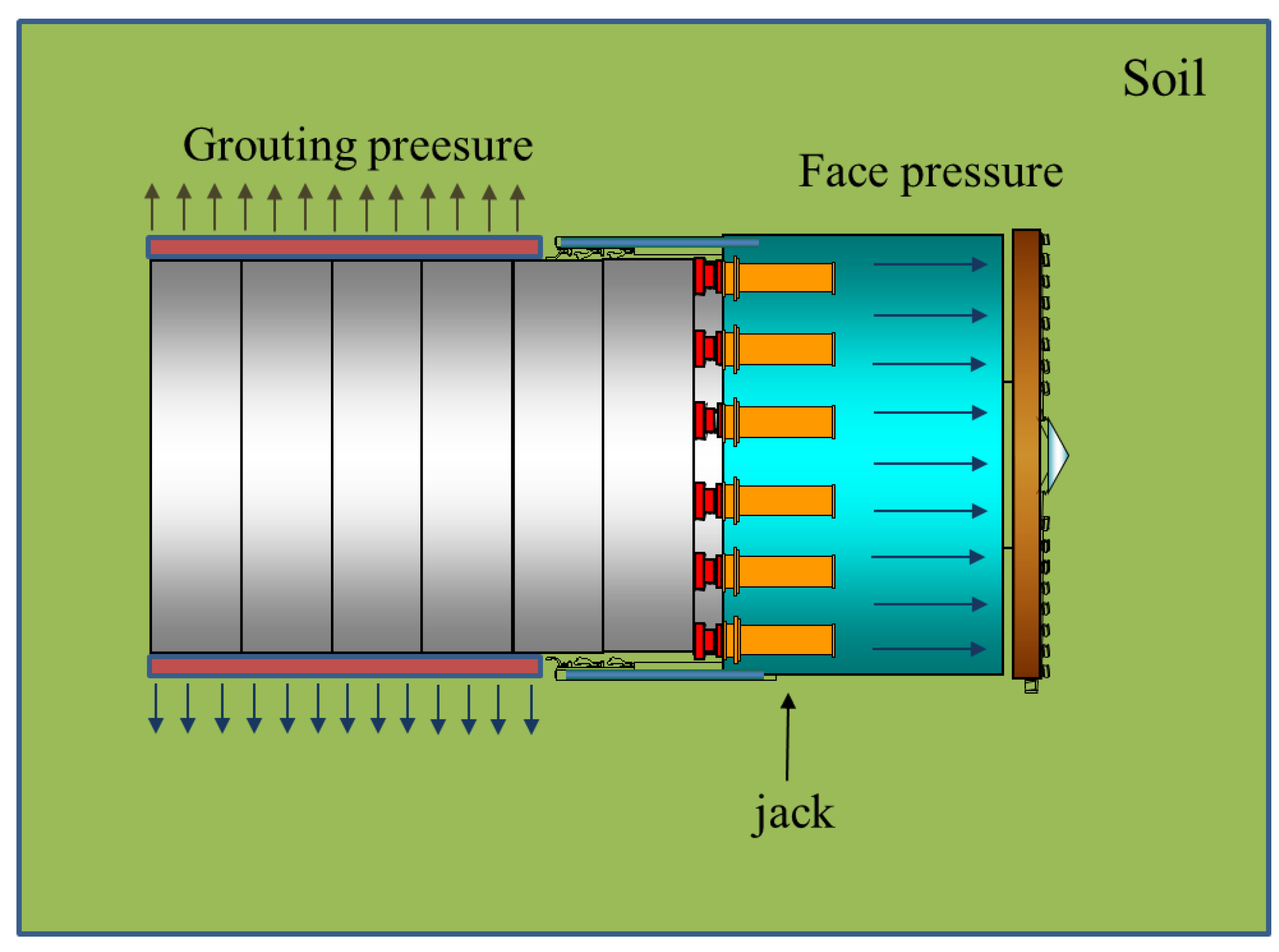
3.1. Synchronous Grouting Pressure Control of Shield

The grouting pressure during the shield tunneling beneath the river is the main factor controlling the influence of the shield tunnel on the surrounding soil [19]. The grouting pressure needs to balance the stresses in the soil around the tunnel [20,21]. The synchronous shield grouting pressure examined in this paper is used to set the location of the grouting holes on the tube sheet at the end of the tube sheet and inject the slurry while advancing. Since the mud film can effectively reduce the permeability of the slurry during the synchronous grouting process, the permeability between the slurry and the soil can be ignored when analyzing the grouting pressure [22]. Figure 3 shows a model of the simultaneous grouting pressure in the gap between the shield segment and the soil. A reasonable grouting pressure needs to be determined based on the diffusion properties of the slurry. Based on the existing research [7,15], the formula for calculating the synchronous grouting pressure is improved by combining the characteristics of synchronous grouting pressure in the shield tunnel, as described below.
In this study, the following assumptions were made based on existing studies and the characteristics of post-wall grouting in the shield tunneling.
  • Due to the presence of the mud cake, the infiltration between the slurry and the soil at the tunnel face can be ignored, and only the pressure-density effect of the slurry on the soil during the grouting process was considered.
  • Assuming that the grout body is hemispherical in the soil, the compression grouting process is equivalent to the expansion of a hemispherical hole with a radius Ru in a semi-infinite soil body (Figure 4a), creating a stress-affected zone around the spherical hole. This stress-affected zone consists of a plastic zone and an elastic zone (Figure 4b).
  • The slurry and soil particles are incompressible and the effect of gravity on soil compression was not considered.
According to the elastoplastic theory, the grouting pressure outside the segments is expanded synchronously.
d σ r d r + 2 σ r σ θ r = 0
where σ r and σ θ are the radial stress and circumferential stress in the soil, respectively.
Assuming the initial radius of the hemispherical slurry is R0, the radius during the expansion of the slurry is Ru and the radius of the elastoplastic interface is Rp, the geometric equation is as follows:
ε r = d u r d r ;   ε θ = u r d r
The physical equation is as follows:
ε r = σ r 2 v σ 0 E ;   ε θ = ( 1 v ) σ 0 v σ r E
The boundary conditions are as follows:
σ r ( R u ) = P ;   lim r σ r = P 0
where P0 is the shield chamber pressure, and P is synchronous grouting pressure.
According to the Moore–Coulomb yield criterion,
σ r α σ θ = y
where α = 1 + sin φ 1 sin φ ; y = 2 c cos φ 1 sin φ .
As the grout amount increases in the shield tail, the grouting pressure also gradually increases, causing the soil to gradually enter a yielding state. Based on the shield chamber pressure monitored by the shield machine, the synchronous grouting pressure can be calculated using the following equation:
P = P 0 + 2 y + ( α 1 ) P 0 2 + α
On the other hand, the tunnel face pressure can also be theoretically calculated based on the burial depth of the tunnel using the following equation,
P 0 = K 0 ( γ H + γ w H 0 + q )
P = K 0 ( γ H + γ w H 0 + q ) + 2 y ( α 1 ) P 0 K 0 ( γ H + γ w H 0 + q ) 2 + α
where K 0 is the lateral pressure coefficient of the soil; γ is the buoyant unit weight of the soil; γ w is the unite weight of water; q is the applied load; H is the thickness of the soil layer above the water level; and H 0 is the thickness of the soil layer below the water level.
For the shield tunnel conditions, the following values of the parameters were adopted: the average soil weight 19.54 kPa; ground overload q 20 kPa; apparent cohesion C 15.6 kPa; tunnel depth variation range H 9.69–21.34 m. Figure 5 compares the measured grouting pressure, the grouting pressure calculated by Equation (6) using measured face pressure and the grouting pressure calculated by Equation (8) according to tunnel depth when tunneling beneath the Jurong River. The results show that the grouting pressure calculated by Equation (6) agrees well with the actual grouting pressure measured in the field. Although Equation (8) considers the effect of the variation of the tunnel depth on the grouting pressure, the surface load changes are also an important factor to determine the grouting pressure and is not considered in Equation (8). This results in the discrepancy between the grouting pressure calculated by Equation (8) and the measured data in the field. In practice, the shield passed safely beneath the river section without having a significant negative impact on the upper river and the adjacent pile foundations, suggesting that Equation (6), which can calculate the grouting pressure based on the face pressure as well as the soil limit damage criterion, may provide good guidance for the shield tunnel.

3.2. Relationship between Shield Grouting Pressure and Grouting Volume

Theoretically, the synchronous grout amount (i.e., the volume of the grouting materials) is the volume of the gap in the shield tail [23,24]. However, other factors such as correction during shield advancement, grout penetration (related to geological conditions) and consolidation and shrinkage of grouting materials also affect the grout amount [25]. Based on Gou [15], the following equation was proposed to calculate synchronous grout amount,
Q = V m
where Q is grout amount/volume (m3); m is grouting rate (usually 1.4–2.0, based on the ground condition and tunnel route); V = π 4 ( D 1 2 D 2 2 ) is the shield tail gap (m3); and D1 and D2 are the diameter of soil cut by the blade and the outer diameter of the segment, respectively.
According to Section 3.1, it can be seen that the grouting pressure for shield tunneling beneath the river gradually decreased with the decrease in the tunnel depth (the thickness of the soil layer above the tunnel). The grouting pressure in this section was the smallest, so the grout amount was reduced accordingly. After passing this section, as the buried depth of the tunnel gradually increased, the grout amount also increased accordingly. However, the grouting amount calculated by Equation (9) is a constant value. This is obviously different from the actual grout volume. The amount of grout is related to the shield tunnel ground condition [26]. Although the penetration rate of the slurry is different for different geological conditions, the penetration rate of the slurry under the same ground condition is constant. Therefore, the relationship between grout volume and grouting pressure when shield tunneling beneath the river can be obtained using the measured data obtained in the field, as described below.
The grouting pressure and the grout amount data for the No. 500-700 segments section (before the shield passing the river) are presented in Figure 6. Then, by taking the average of the value of the grout amount for a given grouting pressure, the relationship between grouting pressure P and grout amount Q can be revealed and presented in Figure 7. A linear relationship between the grouting pressure and the grout amount is observed, and the empirical calculation formula is obtained, as shown in Equation (10).
Q = 4.75 + 0.52 P
It should be noted that the relationship between the grouting amount and the grouting pressure depends on various factors, such as ground conditions and the gap between the segment and the surrounding soil. Therefore, Equation (10) may be different for different shield tunneling projects.
Figure 8 presents the grout amount values calculated by Equations (10) and (9) and measured in the field for the No. 680-860 segments section. The results show that the grout amount calculated by Equation (9) is a constant value; the grout amount when tunneling beneath the river is the same as the data in the normal section. This is likely to cause excessive grout pressure when crossing the river, which may affect the safe construction of the tunnel. By contrast, the grout amount calculated using Equation (10) is in good agreement with the field data throughout the investigated range. Therefore, based on the existing shield grouting parameters measured in the field, the relationship between grout amount and grouting pressure can be obtained, and the grout amount in the similar ground condition can be accurately predicted through the fitted equation (Equation (10)). Table 1 summarizes the actual and calculated values of the grout amount when the shield tunnel is beneath the river. It can be seen that the grout amount calculated according to Equation (10) is much closer to the actual value than in Equation (9).

4. Case Studies

During shield tunneling, the tunnel often had to be excavated beneath surface buildings. The settlement curve of the building in the same area of Jurong when tunneling under a six-story building is shown in Figure 9. The building is a brick and concrete structure with a strip foundation. Measurement points on the wall were located 60 cm above the surface, and the total station DiNi03 was used to measure the settlement caused by tunnel construction. Figure 10 shows that the left side of the building experienced significant settlement as the shield tunnel passed by, with a maximum cumulative settlement of 22 mm, whereas the settlement of the right side of the building is negligible. Consequently, the building experienced large differential settlements and significant distortion is expected.
The grouting pressure and face pressure calculated by Equation (6) during tunneling beneath the building are shown in Figure 11. The results show that during the construction between the No. 700 and 820 segments, the face pressure tended to increase locally. The surface building is located above the No. 800-820 segments, and clearly, the building load led to a significant increase in face pressure. It is difficult to accurately calculate the grouting pressure based on the tunnel depth because of the additional load from the building. However, the measured face pressure can directly reflect the influence of the additional load (either from the buildings or other types of loads). When the shield tunnel passed through the building, the ground surface produced very significant settlement. The vertical settlement at the JC-105 measuring point directly above the tunnel reached 23 mm. Therefore, the grouting pressure needs to be adjusted in time according to the effective stress underneath the building, preventing excessive surface settlement from affecting the normal use of the building. According to Equation (6), a reasonable grouting pressure between 0.214 MPa and 0.326 MPa was obtained for tunneling beneath the six-story building. However, the actual grouting pressure on the construction site was set between 0.11 MPa and 0.13 MPa throughout the tunneling process (including when tunneling beneath the building). As the adopted grouting pressure was much lower than the grouting pressure calculated by Equation (6), large surface and building settlements were generated.
The right line shield tunnel caused a large differential settlement of the building. To protect the building, a secondary grouting to the shield tail at the building location was carried out. The slurry was a cement–water–glass slurry with an initial injection pressure of 0.5 MPa, which was increased to 0.6 MPa at the end of the grouting process, with a grouting duration of 0.5 h and a grout amount of 1.2 m3. Ye [27] proposed an exponential relationship between the slurry diffusion distance and the grouting pressure, as expressed in Equation (11). According to Equation (11), the grouting pressure decreases rapidly with the spreading distance of the slurry. Generally, when the diffusion distance is about 0.4 m, the grouting pressure is consistent with the vertical pressure of the formation. A reasonable secondary grouting pressure can be calculated according to the slurry diffusion law. Figure 12 shows the secondary grouting pressure through the whole process. The first 16 grouts were grouted at a grouting pressure determined based on previous experience. The initial grouting pressure was maintained at 0.3–0.5 MPa. Then, it was gradually increased during the grouting process. By the end of the process, the grouting pressure was increased to 0.4–0.6 MPa. The grouting pressure inevitably affected the slurry diffusion distance.
P r = r 0 r ( 1 + 5 2 δ ) ( 1 φ ) 2 r 0 2 199 φ 3 v 0 d r + P i
where the grouting pipe radius r 0 = 0.025   m ; the diffusion distance r = 0.4 m; the soil porosity φ = 0.385 ; the initial speed of the grout v 0 = 0.8   m / s ; the effective volume fraction of grout grains δ = 0.025 ; and the vertical stress at grouting location Pr = 0.19 MPa.
To improve the effectiveness of the secondary grouting, the grouting pressure and grouting time were gradually increased to increase the grouting diffusion radius. According to the monitoring results (Figure 10a), the settlement of the building was stable after the secondary grouting, and there was even a small uplift at some monitoring points, suggesting that the secondary grouting effect was satisfied and the settlement of the building was effectively controlled.
The shield tunneling caused a large settlement of the building. To reduce the impact of the shield tunnel on the surrounding environment, the grouting pressure was subsequently increased to reduce the surface settlement. Figure 13 shows the relationship between the grouting pressure and the tunnel face pressure in the No. 1140-1220 segments section. Results show that the grouting pressure increased from the initial value of 0.128 MPa to 0.21–0.28 MPa, which is close to the value calculated using Equation (6). Figure 14 shows the maximum surface settlement caused by the shield tunnel before and after the adjustment of the grouting pressure. Before the increase in the grouting pressure, the maximum surface settlement was between −15 mm and −25 mm per segment construction. After increasing the grouting pressure, the maximum surface settlement per segment construction ranged from −1.5 mm to −13.2 mm, indicating the need to adjust the grouting pressure to an appropriate value [28]. The results also suggest that Equation (6) can provide good guidance for determining the required grouting pressure in other tunneling projects to reduce the impact of the shield tunnel on the surrounding environment. Figure 15 is a comparison of the grouting pressure calculated according to the equation in this paper and the measured grouting pressure. It can be seen from the figure that the shield tunnel has a large settlement when passing through the building. This is caused by the additional loads from the building leading to increased stresses on the palm surface during the underpass. Equation (6) can be used to accurately estimate the reasonable grouting pressure when passing under a building, thus avoiding large settlement when the shield tunnel passes under a building.

5. Conclusions

In urban shield tunneling, the performance of the grouting at the shield tail is crucial for controlling the deformation of the segments and the ground. In the complex geological conditions, where the ground conditions and surface/subsurface structures vary during the operation of the shield, a constant grouting pressure may not be appropriate to effectively control the ground deformation. Instead, it should be adjusted based on the surrounding environment and the variation of the ground condition. This paper has presented a theoretical and field study on the optimizing of the grouting parameters. The grouting pressure can be dynamically adjusted according to the soil pressure, and the grouting volume can be accurately calculated. The following conclusions can be drawn based on the work.
(1)
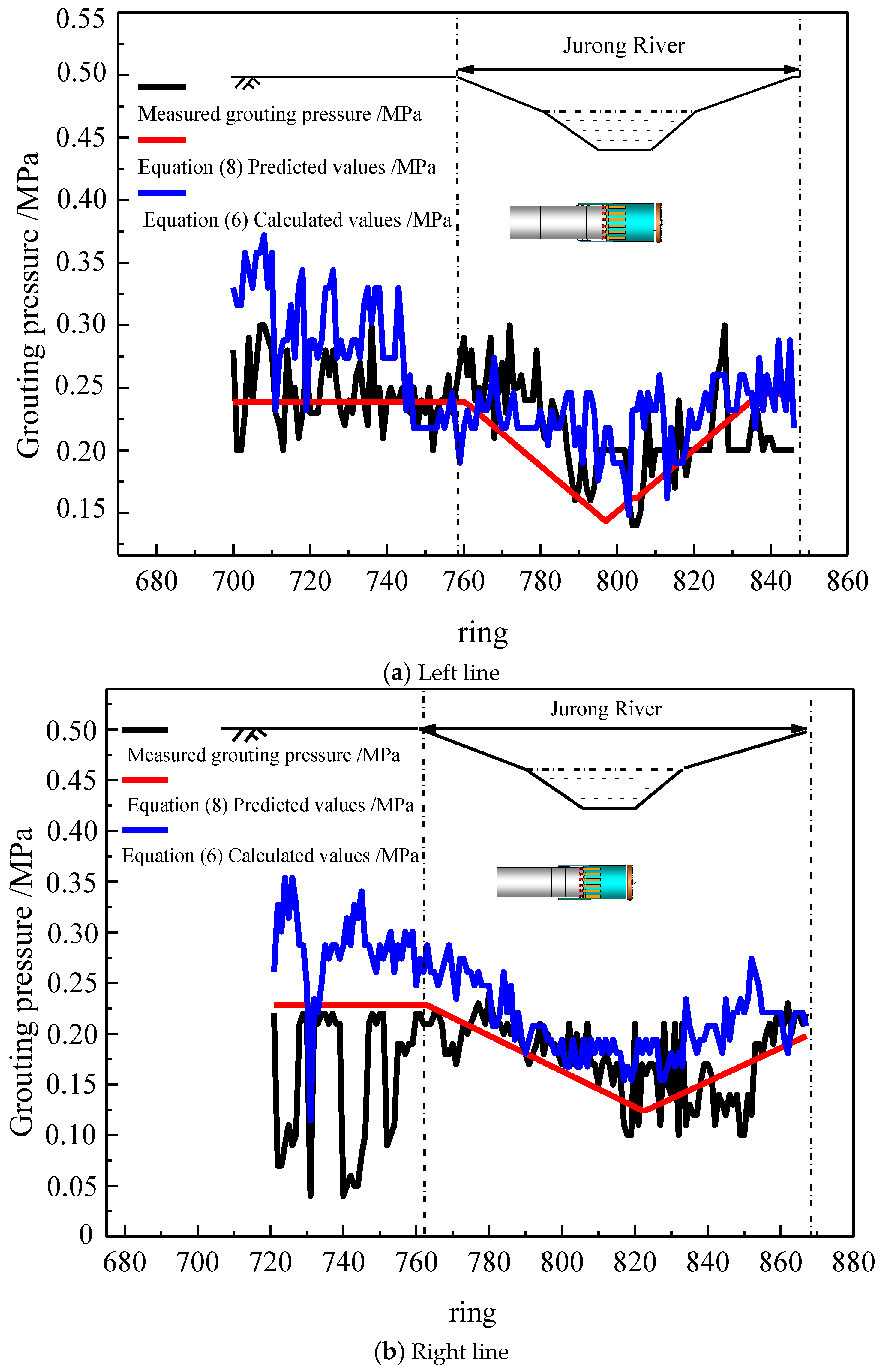
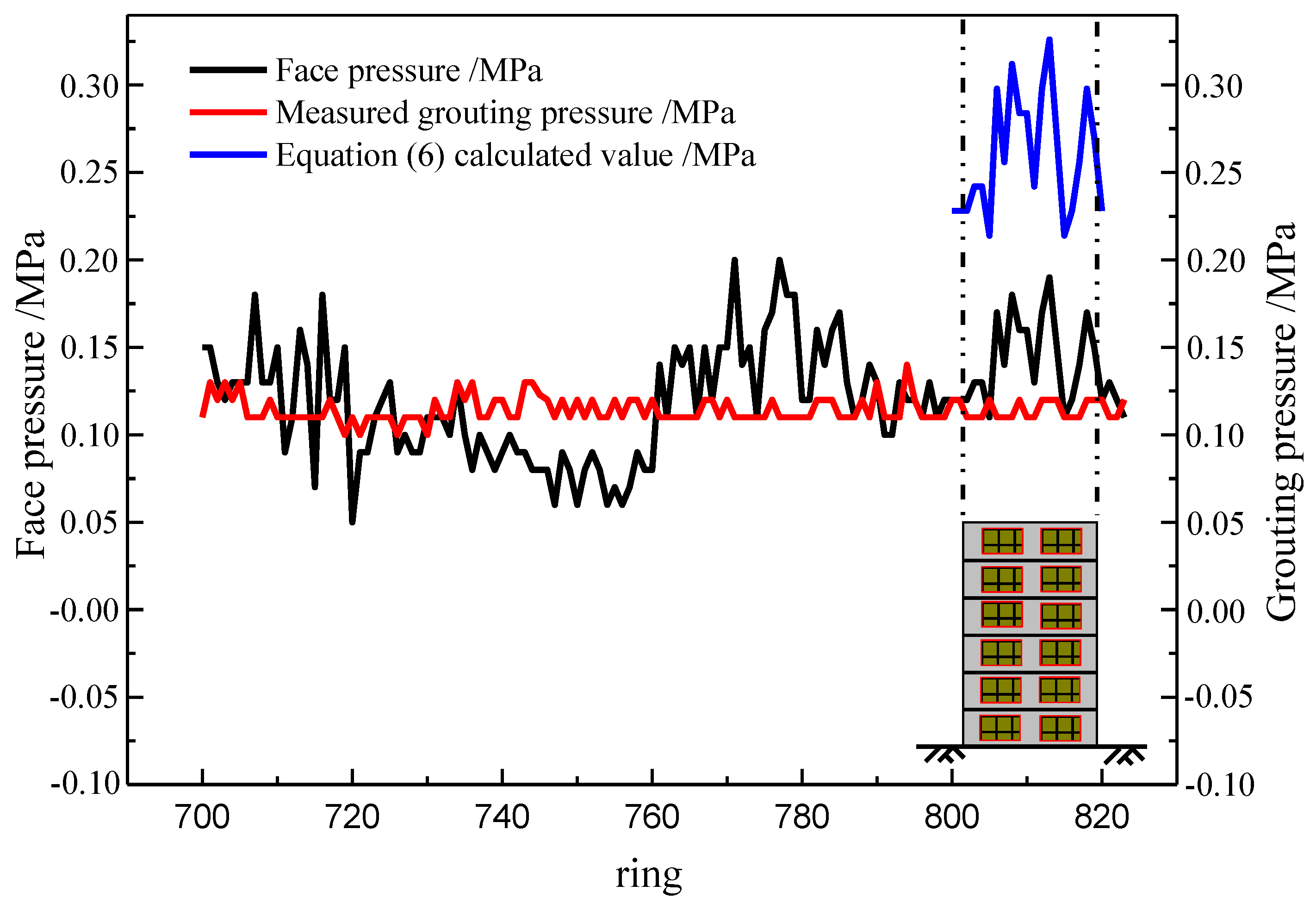
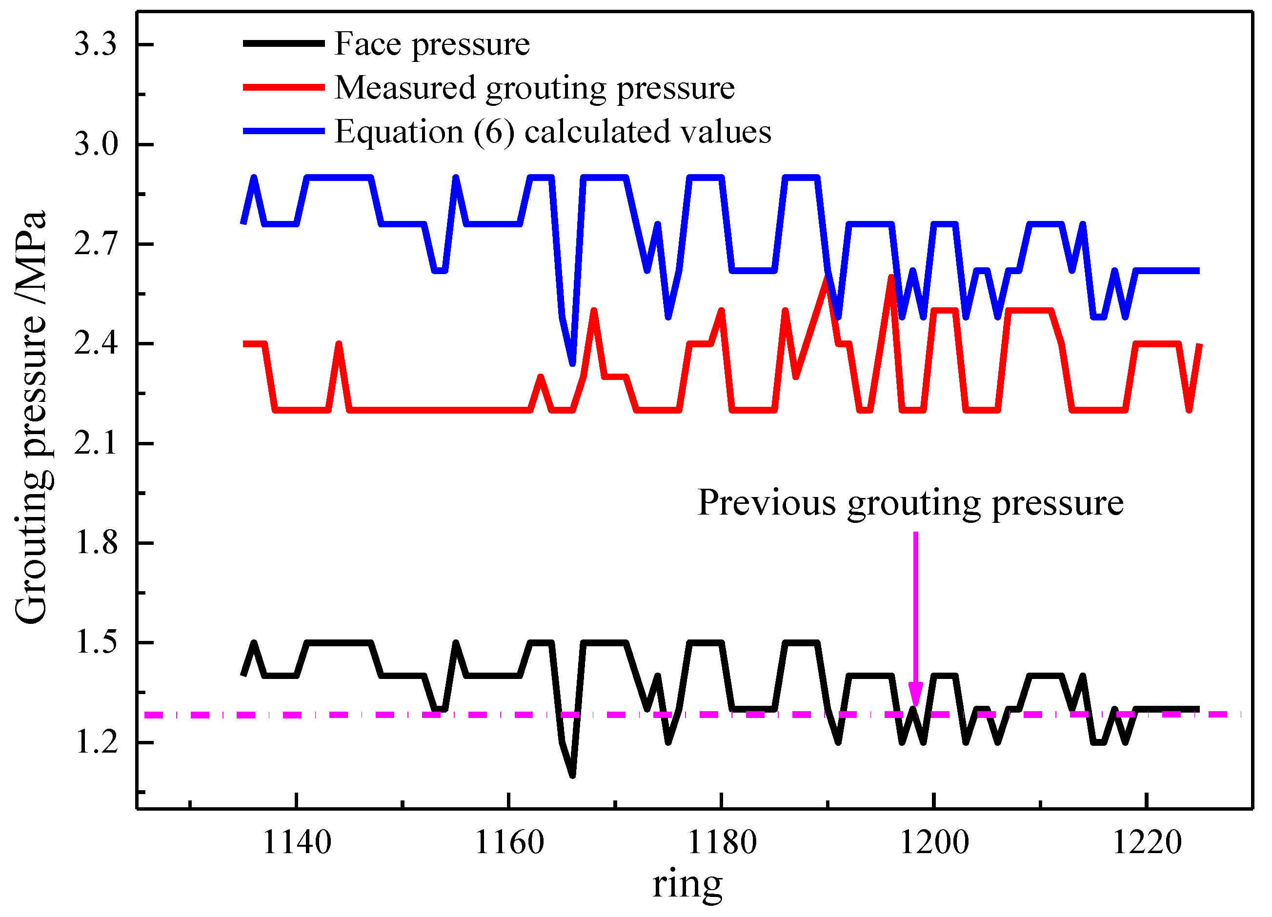
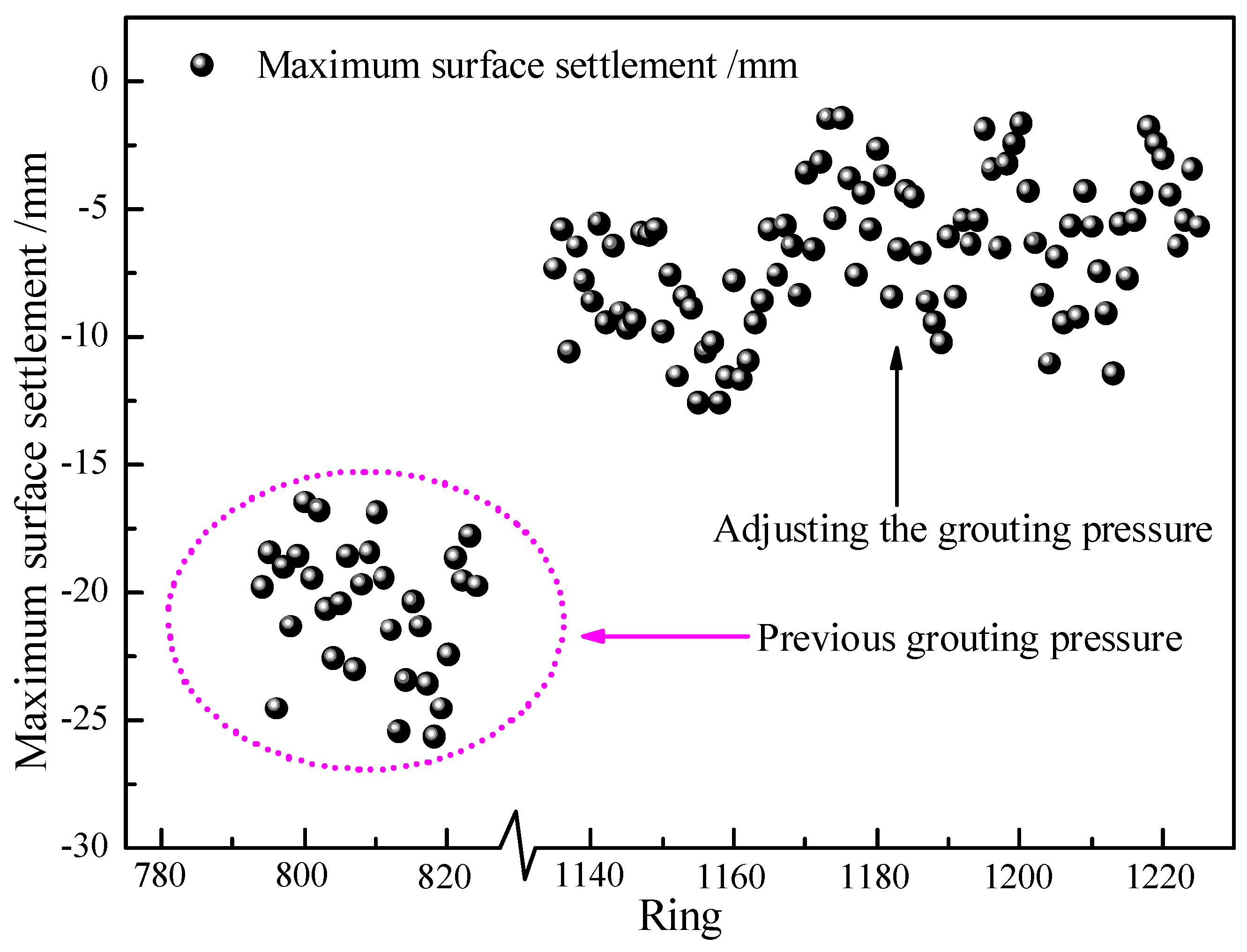
The equation for calculating the synchronous grouting pressure was proposed considering the variation of the surface structure load. Results from the case study suggest that by appropriately adjusting the grouting pressure based on the overlying ground/surface load, the ground settlement can be well controlled and the impact of shield tunneling on the surrounding environment can be reduced.
(2)
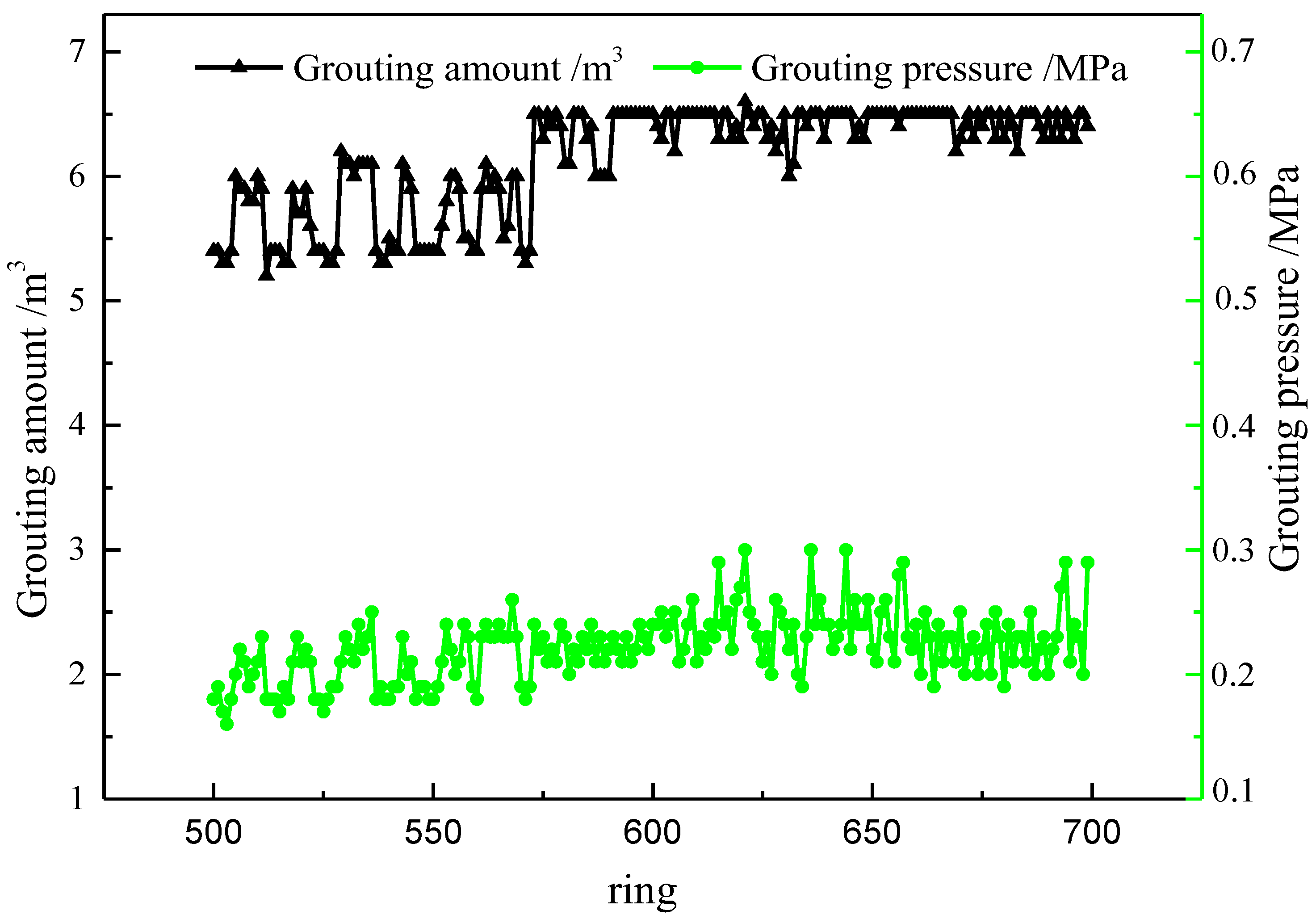
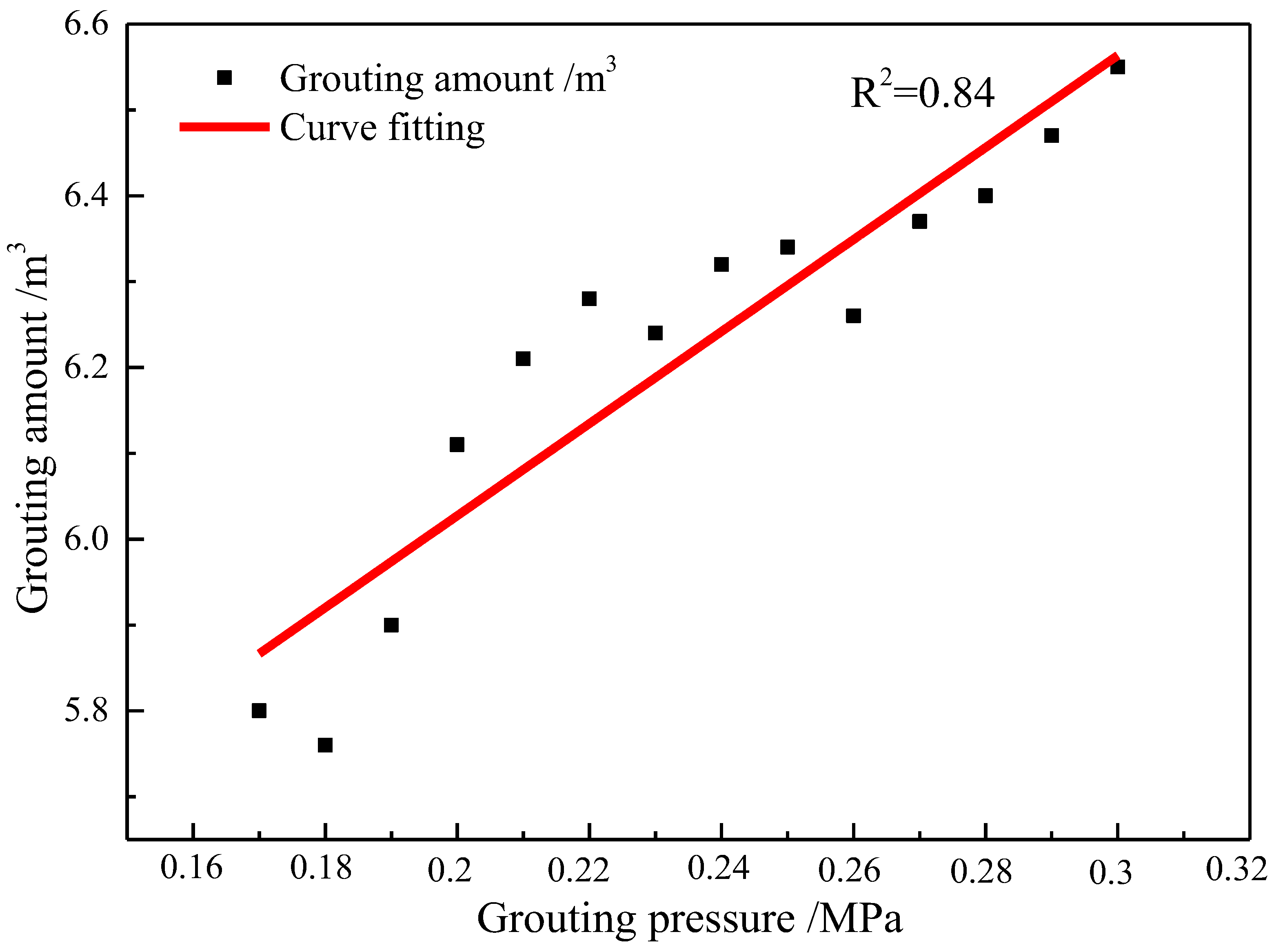
Although the amount of synchronous grouting is related to parameters such as soil conditions, slurry viscosity, shield tail and slurry permeability coefficient, the primary factor affecting the grout amount for a given construction section is the grouting pressure. Based on the linear relationship between the grout amount and grouting pressure, the method that can accurately predict the required grout amount in the subsequent construction section was proposed.
(3)
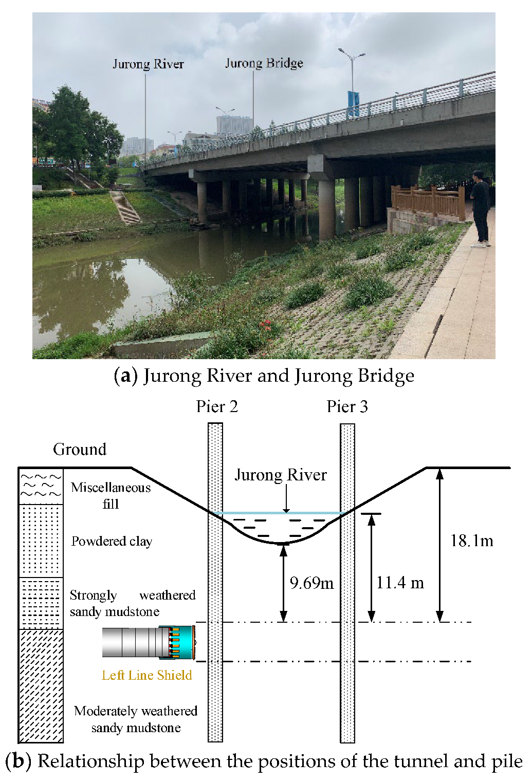
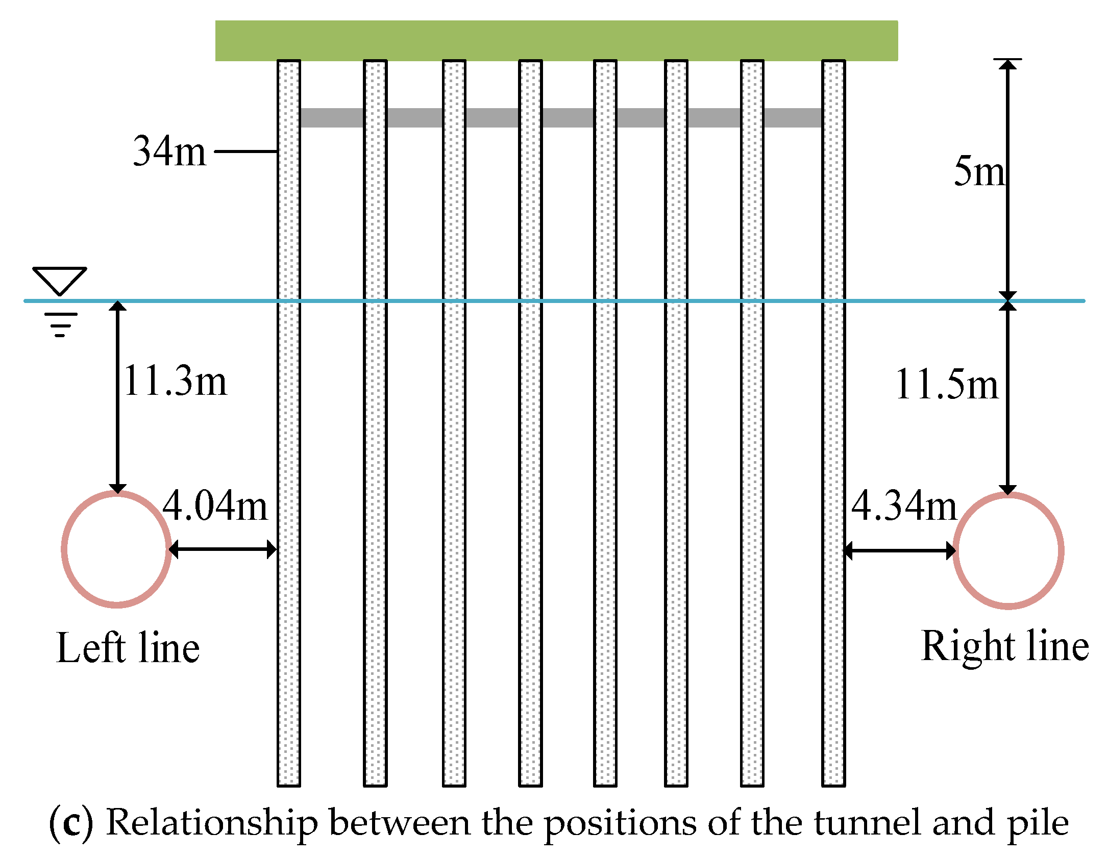
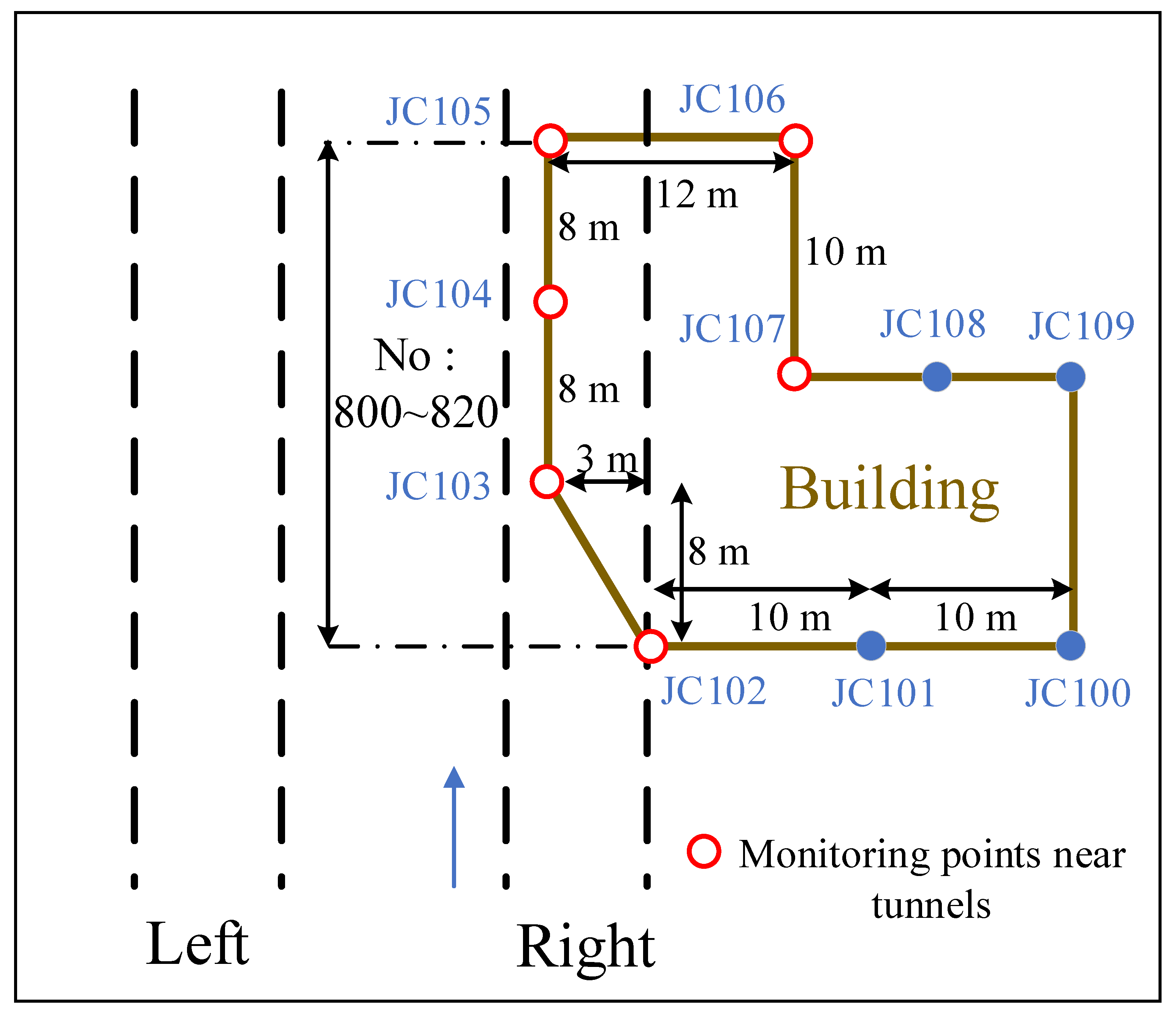
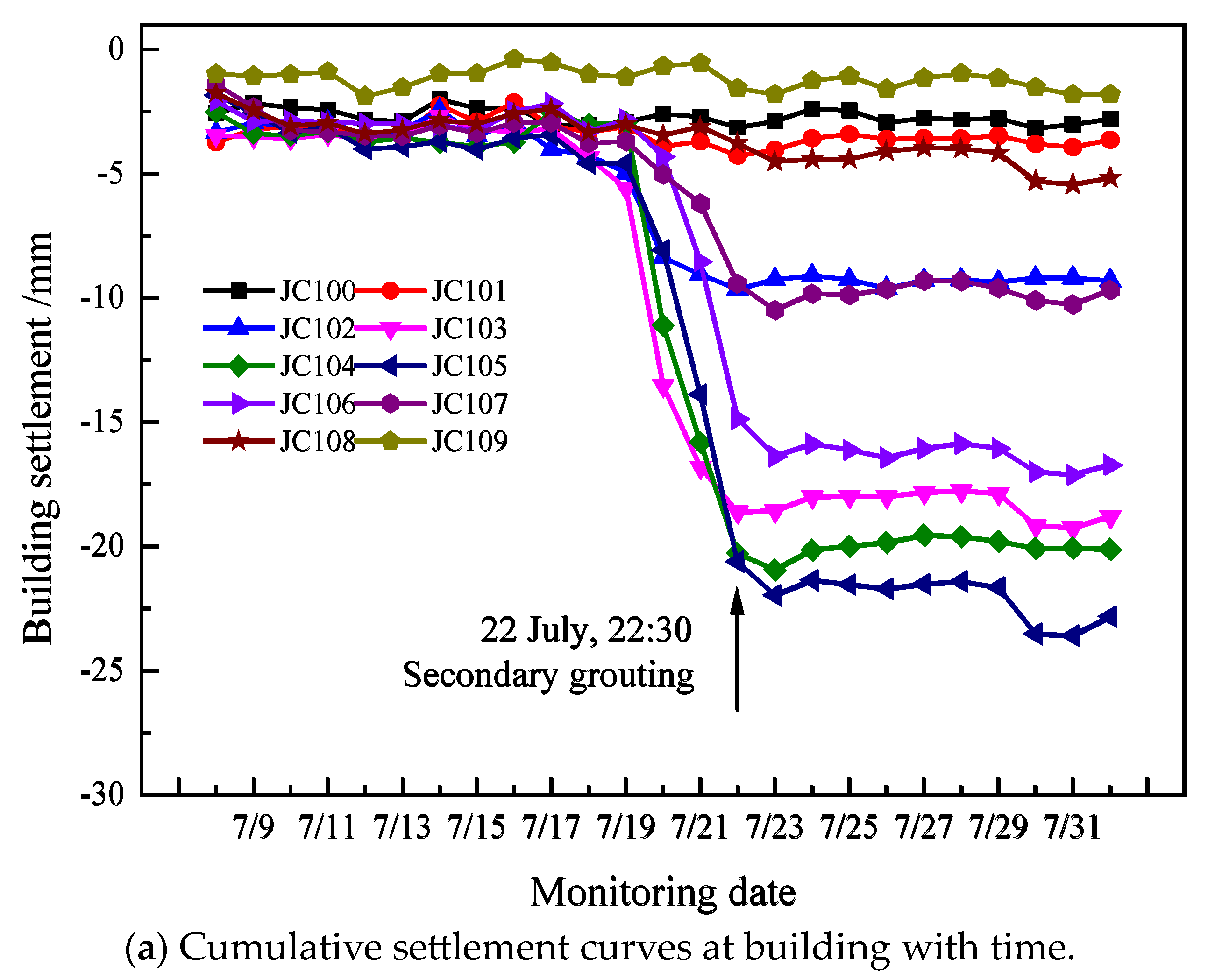
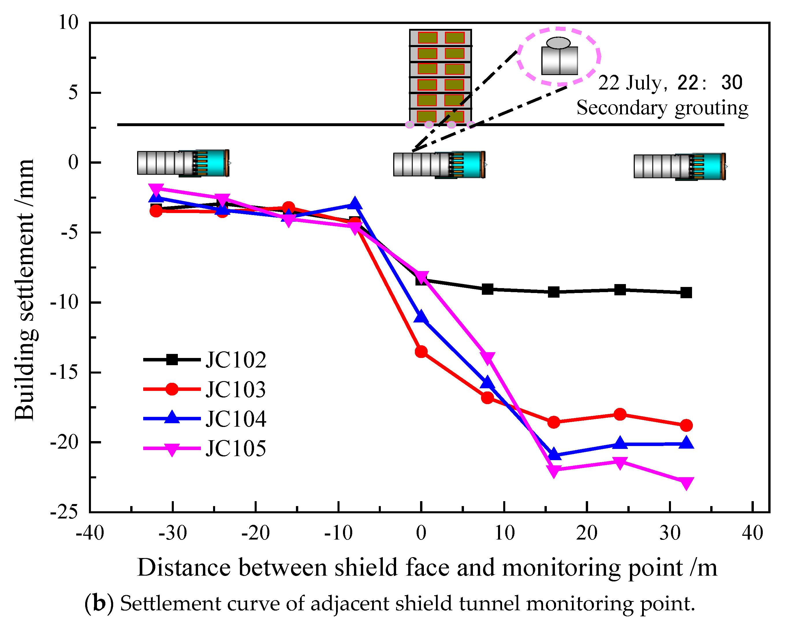
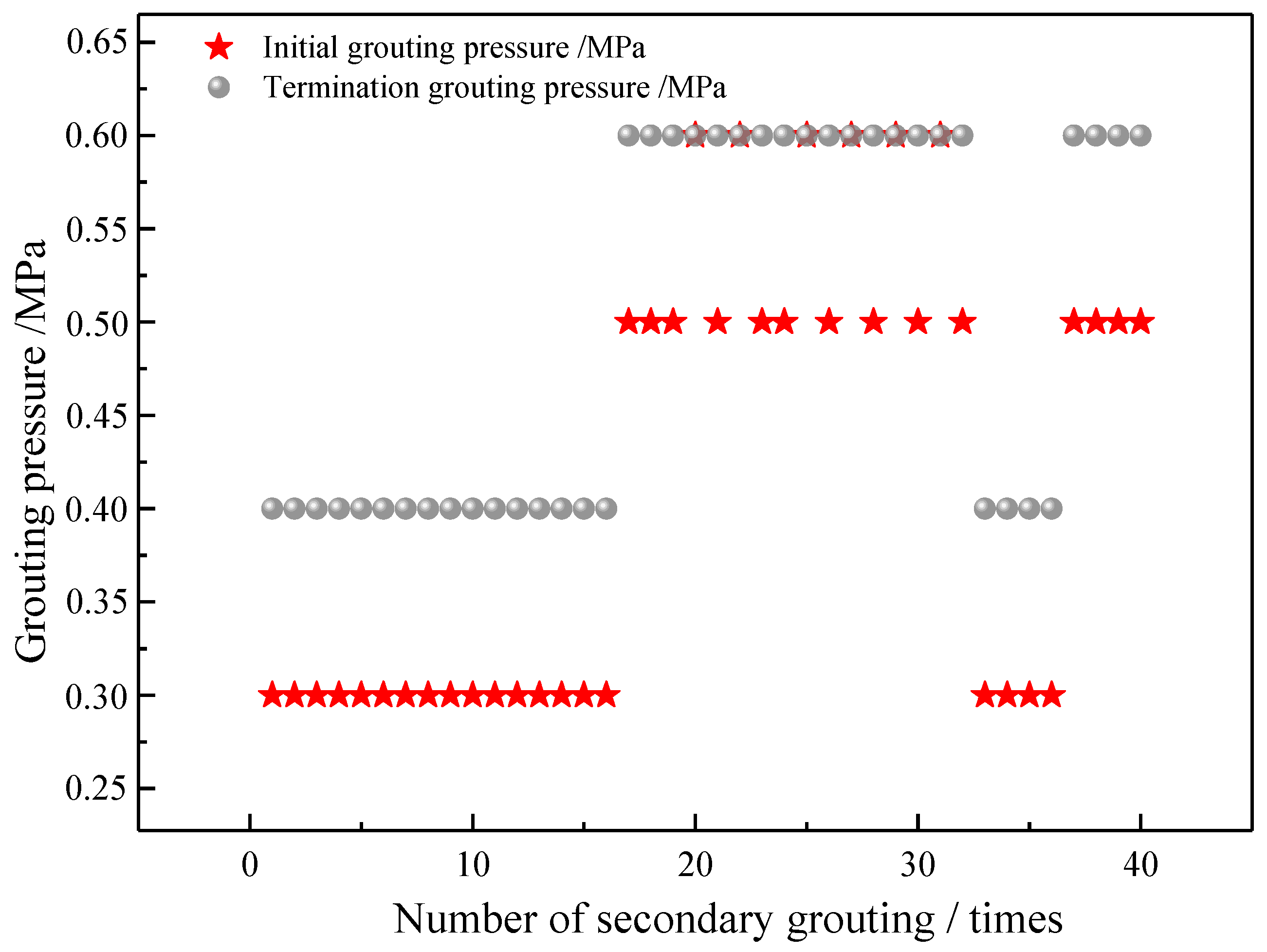
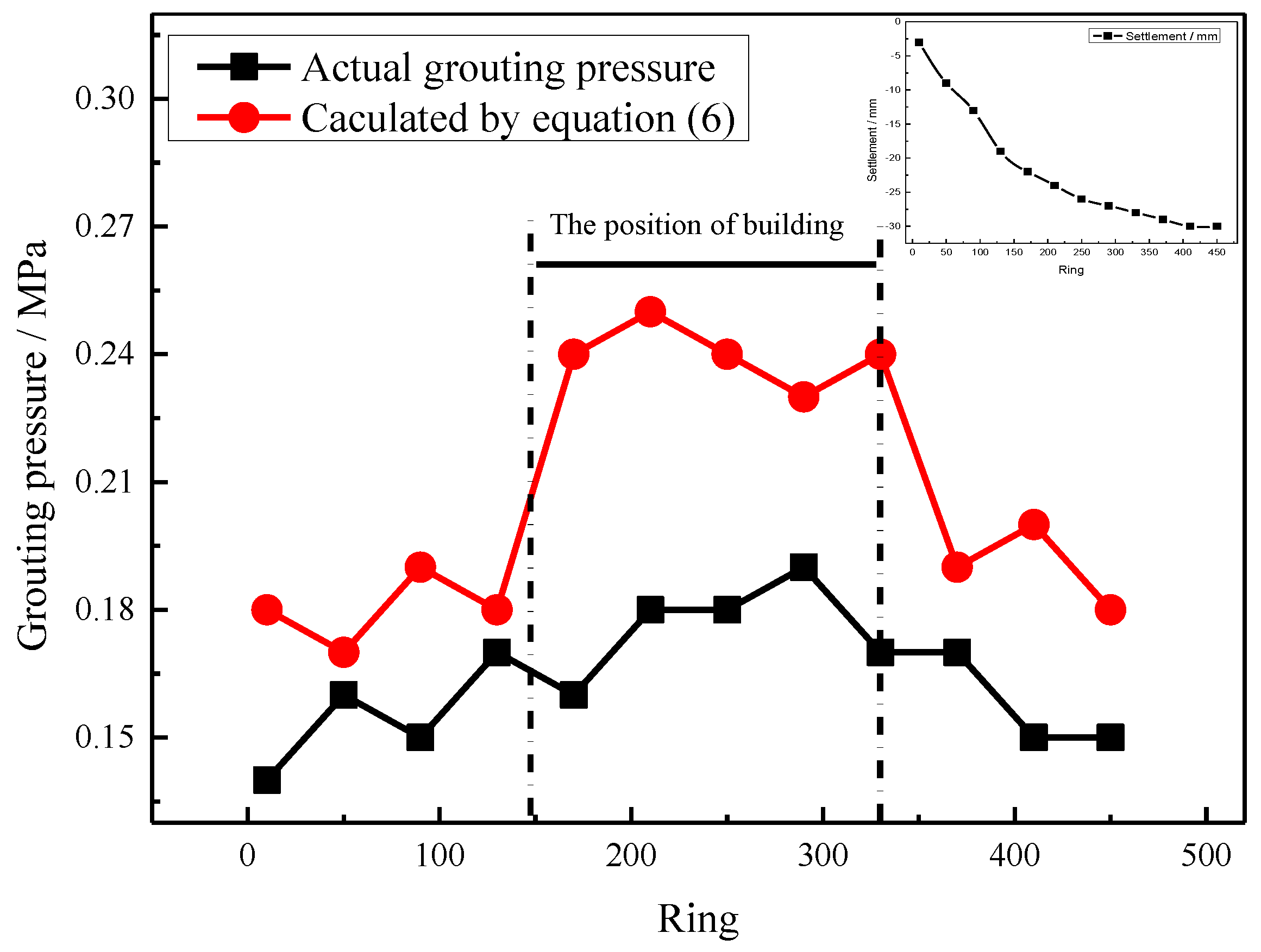
When the shield tunnel is beneath the surface building, grouting pressure should be increased to compensate the additional load from the building. If the grouting pressure is insufficient, the secondary grouting should be carried out in time. Results in the Jurong metro shield tunnel show that by maintaining the secondary grouting pressure as 0.4–0.6 MPa for more than half an hour, the uneven settlement of the building caused by the shield construction was effectively controlled.

Author Contributions

Methodology, M.W.; Software, S.Y. and J.X.; Validation, C.Z.; Resources, M.W.; Data curation, C.Z. and S.Y.; Writing—original draft, C.Z.; Visualization, J.X. All authors have read and agreed to the published version of the manuscript.

Funding

This work was funded by the National Natural Science Foundation of China (Grant No. 52108364), and Shanxi Natural Science Foundation Project (Grant No. 20210302123124).

Data Availability Statement

The original contributions presented in the study are included in the article, further inquiries can be directed to the corresponding author.

Conflicts of Interest

The authors declare no conflict of interest.

References

  1. Xu, J.M.; Franza, A.; Marshall, A.M. Tunnel-framed building interaction: Comparison between raft and separate footing foundations. Géotechnique 2021, 71, 631–644. [Google Scholar] [CrossRef]
  2. Xu, J.M.; Franza, A.; Marshall, A.M. Response of Framed Buildings on Raft Foundations to Tunneling. J. Geotech. Geoenvironmental Eng. 2020, 146, 04020120. [Google Scholar] [CrossRef]
  3. Xie, X.; Wang, Q.; Shahrour, I.; Li, J.; Zhou, B. A real-time interaction platform for settlement control during shield tunnelling construction. Autom. Constr. 2018, 94, 154–167. [Google Scholar] [CrossRef]
  4. Jiang, X.; Zhu, H.; Yan, Z.; Zhang, F.; Huang, X.; Leng, Z.; Xiao, R. Fire-retarding asphalt pavement for urban road tunnels: A state-of-the-art review and beyond. In Fire Technology; Springer: Berlin/Heidelberg, Germany, 2024; pp. 1–41. [Google Scholar]
  5. Yu, C.; Zhou, A.; Chen, J.; Arulrajah, A.; Horpibulsuk, S. Analysis of a tunnel failure caused by leakage of the shield tail seal system. Undergr. Space 2020, 5, 105–114. [Google Scholar] [CrossRef]
  6. Jiang, X.; Zhang, X.; Zhang, X.; Long, L.; Bai, Y.; Huang, B. Advancing Shallow Tunnel Construction in Soft Ground: The Pipe-Umbrella Box Jacking Method. Transp. Res. Rec. 2024, 03611981231225430. [Google Scholar] [CrossRef]
  7. Li, P.; Dai, Z.; Huang, D.; Cai, W.; Fang, T. Impact analysis for safety prevention and control of special-shaped shield construction closely crossing multiple operational metro tunnels in shallow overburden. Geotech. Geol. Eng. 2021, 40, 2127–2144. [Google Scholar] [CrossRef]
  8. Zheng, D.; Bezuijen, A.; Thewes, M. An experimental study on foam infiltration into saturated sand and its consequence for EPB shield tunneling. Tunn. Undergr. Space Technol. 2021, 111, 103878. [Google Scholar] [CrossRef]
  9. Shi, F. Settlement Deformation Analysis and Protection Technology Research of Existing Structures under the Subway Shield Tunneling; Lanzhou University: Lanzhou, China, 2020. (In Chinese) [Google Scholar]
  10. Liu, Y.Z. Study on the Influence of Subway Shield Tunneling on the Settlement of Existing Buildings; Dalian Maritime University: Dalian, China, 2019. (In Chinese) [Google Scholar]
  11. Liao, S.M.; Liu, J.H.; Wang, R.L.; Li, Z.M. Shield tunneling and environment protection in Shanghai soft ground. Tunn. Undergr. Space Technol. 2009, 24, 454–465. [Google Scholar] [CrossRef]
  12. Ye, F.; Qin, N.; Han, X.; Liang, X.; Gao, X.; Ying, K. Displacement infiltration diffusion model of power-law grout as backfill grouting of a shield tunnel. Eur. J. Environ. Civ. Eng. 2022, 26, 1820–1833. [Google Scholar] [CrossRef]
  13. Li, C. Simplified algorithm for grouting pressure and grouting quantity in shield construction. Int. J. Civ. Eng. 2020, 18, 419–428. [Google Scholar] [CrossRef]
  14. Jiang, X.; Zhu, H.; Yan, Z.; Zhang, F.; Ye, F.; Li, P.; Huang, B. A state-of-art review on development and progress of backfill grouting materials for shield tunneling. Dev. Built Environ. 2023, 16, 100250. [Google Scholar] [CrossRef]
  15. Gou, C. Research on Grout Diffusion Mechanism behind the Shield Tunnel Wall; Chang’an University: Xi’an, China, 2013; (In Chinese). [Google Scholar] [CrossRef]
  16. Xu, J.; Zheng, L.; Song, G.; Zhang, D.; Sheil, B.; Marshall, A. Effects of embedded walls on tunnelling-induced sandy ground displacements: A numerical investigation. Géotechnique, 2024; in press. [Google Scholar] [CrossRef]
  17. Xu, J.; Gui, J.; Sheil, B. A numerical investigation of the role of basements on tunnel-frame interaction in sandy soil. Comput. Geotech. 2024, 169, 106197. [Google Scholar] [CrossRef]
  18. Xie, X.Y.; Zhai, J.L.; Biao, Z. Back-fill grouting quality evaluation of the shield tunnel using ground penetrating radar with bi-frequency back projection method. Autom. Constr. 2021, 121, 103435. [Google Scholar] [CrossRef]
  19. Liu, X.X.; Shen, S.L.; Zhou, A.; Xu, Y.S. Evaluation of foam conditioning effect on groundwater inflow at tunnel cutting face. Int. J. Numer. Anal. Methods Geomech. 2019, 43, 463–481. [Google Scholar] [CrossRef]
  20. Fang, Y.; He, C.; Nazem, A.; Yao, Z.; Grasmick, J. Surface settlement prediction for EPB shield tunneling in sandy ground. KSCE J. Civ. Eng. 2017, 21, 2908–2918. [Google Scholar] [CrossRef]
  21. Hai, L.; Xie, X.Y.; Sato, M. Accurate thickness estimation of a backfill grouting layer behind shield tunnel lining by CMP measurement using GPR. In Proceedings of the 14th International Conference on Ground Penetrating Radar, Shanghai, China, 4–8 June 2012; pp. 137–142. [Google Scholar] [CrossRef]
  22. Sun, Y.; Liu, D.; Wang, G. Experimental Study on the Effects of New Foam on the Improvement of Sandy Soil for Earth Pressure Balance Shield. Buildings 2023, 13, 682. [Google Scholar] [CrossRef]
  23. Li, J.K.; Hou, Q.H.; Liang, W.J. Analysis of Dalian Subway Tunnel Shield Construction Impact with Engineering Materials and Engineering Mechanics on Existing Bridge Pier. Adv. Mater. Res. 2014, 848, 96–99. [Google Scholar] [CrossRef]
  24. Li, Z.P.; Li, S.C.; Liu, H.J. Experimental Study on the Reinforcement Mechanism of Segmented Split Grouting in a Soft Filling Medium. Processes 2018, 6, 131. [Google Scholar] [CrossRef]
  25. Rafi, J.Y.; Stille, H. Basic mechanism of elastic jacking and impact of fracture aperture change on grout spread, transmissivity and penetrability. Tunn. Undergr. Space Technol. 2015, 49, 174–187. [Google Scholar] [CrossRef]
  26. Zhang, N.; Shen, S.L.; Zhou, A.N.; Lyu, H.M. Challenges of earth pressure balance tunnelling in weathered granite with boulders. Proc. Inst. Civ. Eng.-Geotech. Eng. 2021, 174, 372–389. [Google Scholar] [CrossRef]
  27. Ye, F.; Yang, T.; Mao, J.H. Half-spherical surface diffusion model of shield tunnel back-fill grouting based on infiltration effect. Tunn. Undergr. Space Technol. 2019, 83, 274–281. [Google Scholar] [CrossRef]
  28. Bezuijen, A.; Talmon, A.M.; Kaalberg, F.J. Field measurements of grout pressures during tunnelling of the sophia rail tunnel. J. Jpn. Geotech. Soc. 2008, 44, 39–48. [Google Scholar] [CrossRef]
Figure 1. House cracking caused by shield tunnel.
Buildings 14 02799 g001
Figure 2. The relationship between the locations of the tunnel and the Jurong River.
Buildings 14 02799 g002aBuildings 14 02799 g002b
Figure 3. Schematic diagram of shield tunnel grouting.
Buildings 14 02799 g003
Figure 4. Slurry diffusion model.
Buildings 14 02799 g004
Figure 5. The grouting pressure curve of actual measurement and theoretical calculation.
Buildings 14 02799 g005
Figure 6. Relationship between grouting pressure and grouting volume.
Buildings 14 02799 g006
Figure 7. Fitting diagram of grouting volume and grouting pressure.
Buildings 14 02799 g007
Figure 8. Comparison curve between calculated grouting amount and measured grouting amount.
Buildings 14 02799 g008
Figure 9. Schematic diagram of house monitoring points.
Buildings 14 02799 g009
Figure 10. Cumulative settlement curves at building monitoring points.
Buildings 14 02799 g010aBuildings 14 02799 g010b
Figure 11. Face pressure and grouting pressure.
Buildings 14 02799 g011
Figure 12. Secondary compensation grouting pressure diagram.
Buildings 14 02799 g012
Figure 13. Grouting pressure and face pressure.
Buildings 14 02799 g013
Figure 14. Maximum surface settlement per ring.
Buildings 14 02799 g014
Figure 15. Maximum surface settlement per ring [11].
Buildings 14 02799 g015
Table 1. Grouting volume in the interval section under the river.
Measured Grouting Volume/m3Equation (9)/m3Fitting Equation (10)/m3
Left line562.7583.3574.7
Right line588624601.3
Disclaimer/Publisher’s Note: The statements, opinions and data contained in all publications are solely those of the individual author(s) and contributor(s) and not of MDPI and/or the editor(s). MDPI and/or the editor(s) disclaim responsibility for any injury to people or property resulting from any ideas, methods, instructions or products referred to in the content.

