Article

Experimental Study on the Failure Mechanism of Finned Pile Foundation under Horizontal Cyclic Loads

by
Lunliang Duan
1,2,3,
Meiling Fan
3,
Bolin Zhan
3,
Haicui Wang
1,
Haiming Liu
1,
Guangwu Tang
1 and
Bo Geng
1,*
1
State Key Laboratory of Bridge Engineering Structural Dynamics, China Merchants Chongqing Communications Technology Research and Design Institute Co., Ltd., Chongqing 400067, China
2
Key Laboratory of Bridge Earthquake Resistance Technology, Ministry of Communications, Chongqing 400067, China
3
College of River and Ocean Engineering, Chongqing Jiaotong Univeristy, Chongqing 400067, China
*
Author to whom correspondence should be addressed.
Buildings 2024, 14(9), 2814; https://doi.org/10.3390/buildings14092814 (registering DOI)
Submission received: 2 August 2024 / Revised: 28 August 2024 / Accepted: 4 September 2024 / Published: 7 September 2024
(This article belongs to the Special Issue Engineering Disaster Prevention and Performance Improvement)

Abstract

:
In order to study the failure mechanism of a finned pile foundation under horizontal cyclic loads, a physical model test of the pile–soil interaction of finned pile is designed in this paper. Based on the model tests, the pile top displacement, the cyclic stiffness of the pile foundation, and the response of pore water pressure within the soil around the pile were fully studied for the finned pile foundation under horizontal cyclic loads. It is found that the cyclic stiffness attenuation of the finned pile foundation is more severe than that of a regular single pile foundation, but the final stiffness at equilibrium is still greater than that of a regular single pile foundation. The accumulation of horizontal displacement at the pile top and pore water pressure within the soil around the pile mainly occurs in the first 1000 loading cycles, and an increase in fin plate size will reduce the magnitude of pore water pressure and pile top displacement. This study can not only deepen the understanding of the failure mechanism of finned pile foundation under horizontal cyclic loads, but also provide guidance for the design of the finned pile foundation.

1. Introduction

With the continuous consumption of non-renewable energy worldwide and the increasing emphasis on the natural environment in various countries, the renewable energy is gradually receiving attention from the energy industry. Among numerous renewable energies, wind energy occupies a high position, and the development of offshore wind power has been booming in recent years. By the end of 2023, the global cumulative installed capacity of offshore wind power reached 75.2 GW, an increase of about 17.2%, accounting for about 7.3% of the global cumulative installed capacity of wind power. At present, more and more countries are increasing their investment and development of offshore wind power, among which the offshore wind power in Europe, North America, Latin America, and some countries in Asia is developing rapidly. Now, China’s newly added offshore wind power installed capacity in 2021 was 16.9 GW, accounting for 87% of the world’s newly added production scale. Its total installed capacity reached 25.89 GW, making it the world’s largest offshore wind power market. On a global scale, offshore wind power accounts for approximately 0.3% of the world’s energy supply. According to traditional predictions, the proportion of offshore wind power generation in global energy supply is expected to reach 6–9% by 2050, with a significant impact on the world’s energy composition [1,2], and the cumulative installed capacity of global offshore wind power will reach 380 GW in 2030. In fact, traditional wind energy prediction methods are mainly based on statistical and physical models, which have certain limitations in dealing with uncertainty problems. Artificial intelligence methods have brought new possibilities for wind power prediction, and the advantages are mainly reflected in three aspects: firstly, artificial intelligence methods can process large amounts of complex data and discover hidden patterns; secondly, artificial intelligence methods can flexibly adapt to uncertainty and changes, and have good adaptability to sudden changes in wind speed; finally, artificial intelligence methods have strong adaptive and learning abilities, which can improve the accuracy of wind energy prediction models through continuous learning and optimization.
The site selection of an offshore wind farm can significantly affect the choice of its foundation type. Generally, an offshore wind farm site should be located in areas with abundant wind resources, suitable marine environments, and minimal impact on the surrounding environment. The offshore wind turbine foundations include fixed foundations and floating foundations. The fixed foundations mainly include gravity-based foundations, single pile foundations, etc., and the floating foundations mainly include tension leg platforms, semi-submersible platforms, etc. The choice of offshore wind turbine foundation mainly depends on factors such as water depth, geological conditions, economy, and technical feasibility. Gravity-based foundations are often used in the area with a water depth below 5 m, and single pile foundations are mainly used in the areas with a water depth of 5–40 m. As for areas with a water depth greater than 100 m, floating foundations are mainly used.
Currently, single pile foundations have been widely used in the construction of onshore and offshore wind turbines. Unlike onshore pile foundations, offshore wind turbine foundations mainly bear horizontal loads caused by waves, wind, and rotating blades, and are often applied to the pile foundation in the form of sustained cyclic loads. Offshore wind turbines may experience horizontal loads exceeding 106–108 times throughout the entire lifecycle [3]. Under the long-term loads, the characteristics of the soil around the pile will change, leading to increased structural displacement and, in severe cases, reduced efficiency or even failure of the wind turbine [4,5,6,7,8,9,10]. In order to maximize the advantages of large-diameter single pile foundations and enhance their ability to resist horizontal external loads, the concept of composite single piles have been proposed, which mainly involves adding substructures to the single pile foundation to optimize its horizontal bearing performance. Finned pile is a new type of large-diameter single pile foundation that sets the fin plates on the pile body under the mud surface. It can fully mobilize the resistance of shallow soil and effectively improve the horizontal bearing capacity of the pile foundation. Meanwhile, the finned pile can reduce the pile diameter and lower the construction difficulty while ensuring the horizontal bearing capacity of the pile foundation. There are various types of finned pile foundations, such as friction-wheel pile foundation, multi-fin sheet pile foundation, and foundations of two and four fin sheet pile, and four fin sheet piles. When the water depth exceeds 40 m, the stability of the finned pile foundation is better and the construction cost is lower than that of the single pile foundation.
In recent years, Extensive research have been conducted on the finned pile foundation. Among these, Li Wei et al. [11,12] conducted numerical simulations and model tests on finned piles, and found that finned single piles have a higher horizontal bearing capacity compared to traditional single piles. As the length (L) and width (W) of the fin plate increase, the displacement of the pile body gradually decreases. However, considering the possible problems and economic benefits in actual construction, the fin plate size cannot be too large. It is recommended that the optimal values be D ≤ L ≤ 3 D, D/2 ≤ W ≤ D (D is the pile diameter). In addition, it was found that the presence of fin plates can fully exert the soil resistance of shallow soil. When the depth of the fin plate increases, its ability to improve the horizontal bearing capacity will weaken. Due to the presence of fin plates, the impact of loading in different directions on the pile will vary. The model tests have shown that when the loading direction is at 45° angle to the fin plate, the effect of increasing the bearing capacity is poor. It is also found that both finned single piles and traditional single piles have the same rotation center under horizontal load, located at 0.75 times the burial depth. Chen Canming et al. [13] used the finite element method to study the effects of the shape, size, quantity, burial depth, stiffness, and loading direction of fin plates in clay on the horizontal displacement, bending moment, and soil pressure distribution of fin-added single piles, and proposed an empirical formula for calculating the ultimate bearing capacity. Nasr [14] used laboratory experiments and finite element methods to study the bearing capacity of a finned pile in sandy soil, and analyzed the contributions of two types of fin plates to the bearing performance. It was found that both types of fin plates could increase the horizontal bearing performance of the single pile, but rectangular fin plates had a higher cost-effectiveness. Abongo et al. [15] added three fin plates on the basis of two and four fin plates, and studied the stress laws of several working conditions in sandy soil. Unlike Nasr’s symmetrical arrangement of two fin plates [14], this study also involved the situation where the two fin plates were arranged at 90° angle. In addition, the three fin panels also come in two types: 90° and 120°. Several types of fin plates can improve the bearing capacity of a single pile foundation. Under the same ultimate load, the three types of piles can reduce the pile length by 30–40%. However, due to differences in the effective bearing area corresponding to different loading directions, the bearing effect in different directions is not the same. The pile with two fin plates is particularly sensitive to the load direction, and the lowest is similar to a regular single pile. On the other hand, the pile with three fin plates and four fin plates has less sensitivity to the loading direction. Overall, the bearing capacity of four fin plates is higher than that of three fin plates. For the case of four fin plates, the bearing capacity when the loading direction is 45° to the fin plate is slightly lower than that of 0°. Pei et al. [16] used subroutines to modify the Mohr Coulomb constitutive model of ABAQUS under existing constitutive conditions, enabling it to relatively accurately reflect the softening and hardening behavior of soil. It is found that the improvement of bearing capacity by fin plates weakens with the increase in the relative density of sand, which is particularly evident on rigid short piles. Sakr et al. [17] used model tests to study the bearing performance of finned piles in clay foundations. Their fin plate settings were similar to those of Nasr and Abongo [14,15], and the effects of fin plate length, width, shape, quantity, loading direction, and soil shear strength on the performance of finned piles were investigated. Hu et al. [18] studied the stress characteristics of large-diameter single piles and large-diameter fin piles in soft clay, and found that the two have similar displacement and soil resistance distributions, indicating that by correcting relevant parameters, the current single pile p-y curve can be made applicable to large-diameter finned piles, and relevant correction ideas are proposed.
As for the dynamic response of offshore wind turbine foundations under long-term cyclic loads, Bienen et al. [19] conducted 1 g and 200 g model experiments to study the effects of unidirectional and cyclic loads on finned single piles in sandy soil foundations, and compared their performance with traditional single piles. It is found that installing fin plates at the top of the pile could significantly reduce its horizontal displacement. Under continuous cyclic loads, the ratio (f_N) of the cumulative displacement of the Nth cycle to the displacement of the first cycle does not decrease due to the presence of the fin plate. However, since the fin plate can significantly reduce the displacement of the first cycle, its total cumulative displacement is smaller than that of traditional single piles. This study obtained a prediction model for (f_N) by fitting experimental curves, and introduced it into the prediction model for pile top displacement under general unidirectional loads, resulting in a prediction model for pile top displacement under cyclic loads.
The existing research has deepened the understanding of the bearing performance of finned pile foundations [20,21,22,23]. However, the structural form of single pile foundations on the side fins is relatively complex and novel, and the failure characteristics of finned pile foundations under horizontal cyclic loads are still not clear enough. Therefore, this paper analyzes the response laws of the finned pile foundation and the soil under horizontal cyclic loads by designing a model test of the pile–soil interaction. Furthermore, the failure mechanism of the finned pile foundation under horizontal cyclic loads is revealed. This study can not only deepen the understanding of the failure mechanism of finned pile foundations under horizontal cyclic loads, but also provide guidance for the design of finned pile foundations.

2. Physical Model Test

In this section, the sketch of the physical model test is illustrated. The general process of model experiments is as follows:
(1)
Design the horizontal cyclic loading system according to the research needs.
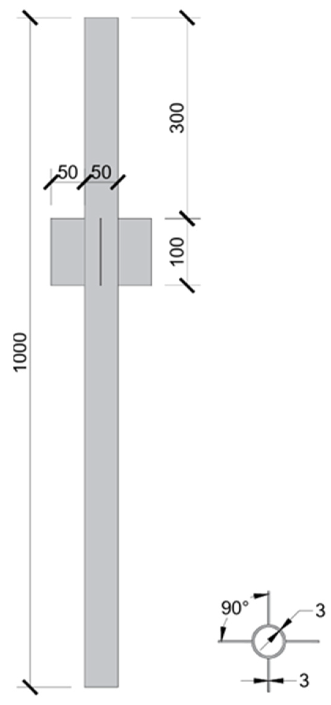
(2)
Make the model pile according to the requirements of scale and material, and prepare the model soil in combination with the soil characteristics in the wind farm.
(3)
Arrange the sensors and fix the model pile.
(4)
Fill the model soil in layers to the test tank. Before filling the model soil, it is necessary to soak the soil with water to make it completely saturated.
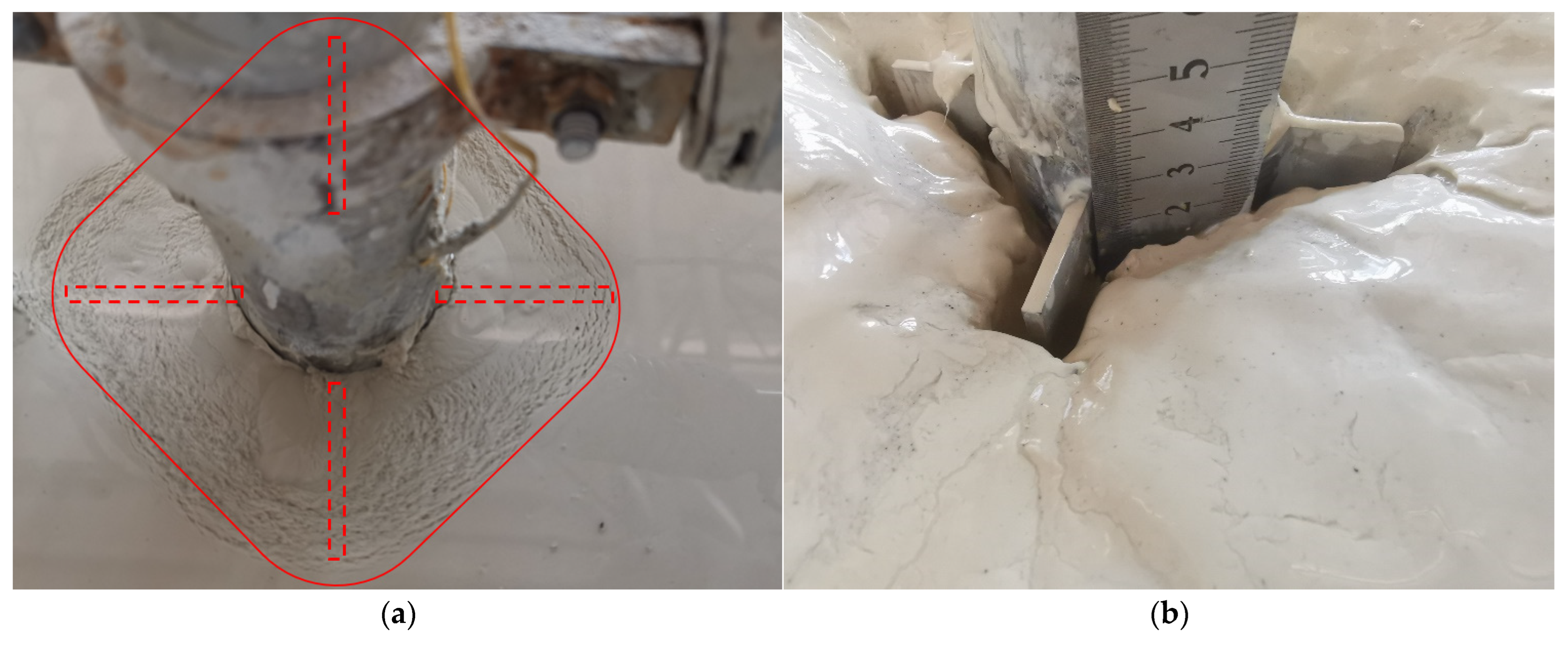
(5)
Start the motor to apply horizontal cyclic load to the finned pile, and record the readings of each sensor.
During the physical model experiment, a steel pipe pile foundation with a diameter of 5 m and a length of 70 m in actual engineering was used as the engineering background, and the pile foundation was scaled down at a ratio of 1:100. The model pile is made of aluminum alloy material with an elastic modulus of 71 GPa. The main body is a hollow structure, as shown in Figure 1. The outer diameter of the model pile is 50 mm, the wall thickness is 3 mm, and the total length is 1000 mm. Four side fin plates with a length of 100 mm and a width of 50 mm are welded below 300 mm, and the angle between the fin plates is 90°. The model pile with strain gauges attached needs to be coated with insulation glue and epoxy resin at the interface between the strain gauges and the wires to prevent the influence of pore water inside the soil on the measurement results during the test process. During the experiment, 700 mm below the fin plate was embedded in the soil, and 300 mm above it was exposed.
In this study, the choice of the soil type refers to the seabed condition of a wind farm project in Jiangsu province, China. The grading curve of kaolin soil used in the experiment is shown in Figure 2 and the soil properties are shown in Table 1. The liquid limit and plastic limit joint determination method was used to determine the liquid limit and plastic limit of the model soil, which was used to calculate the plasticity index. Meanwhile, the water content of the model soil was evaluated based on the oven drying method and the other soil properties are sourced from soil sellers.
In order to obtain the stress and deformation status of the soil and piles during the loading process, data such as pore water pressure inside the soil, pile strain, and pile top displacement were measured in this experiment. The sensors used include 7 corresponding transformers, 1 displacement sensor, 5 pore water pressure sensors, and 1 tension pressure sensor. The layout scheme of each sensor is shown in Figure 3. The displacement sensor is set at the top of the pile, the tension and pressure sensor is set at 2 D above the ground, the pore water pressure sensor P1 is set at 1 D below the mud surface, and the other four sensors are spaced 3 D downwards. Strain gauges are attached to both sides of the pile, spaced 2 D apart, and the top pair is attached to the mud surface.
This experiment was conducted in a model box composed of tempered glass, steel plates, and concrete. The dimensions of the soil groove were 1.2 m × 1.35 m × 0.9 m, with a soil depth of 0.9 m and a pile foundation depth of 0.7 m. The cyclic loading device, as shown in Figure 4, uses a motor as the loading power, an eccentric wheel to control the load output size, a frequency modulator to control the loading frequency, and a fixed ring to fix the pile and loading device together. Considering the frequency of wave and wind loads in actual marine environments, Naggar and Bentley [24] suggested a loading frequency of 0–1 Hz for the model test. Therefore, the loading frequency for this model test was set to 1 Hz.
In the course of the experiment, the motor is used to drive the eccentric wheel to drive the coupling to realize the horizontal cyclic loads of the pile foundation, and the eccentric wheel with different eccentricities is replaced as needed. The horizontal cyclic load can be detected in real time by the tension pressure sensor fixed on the coupling during the installation of the eccentric wheel. When the number of cyclic loads reaches 5000 times or the displacement of the pile foundation at the mud surface exceeds 10 mm, the loading tests are terminated. In this study, one set of ordinary single pile and six sets of fin pile load tests were set up. The fin pile load tests included five sets of cyclic load tests and one set of static load tests. The specific operating conditions are shown in Table 2.

3. Results and Discussions

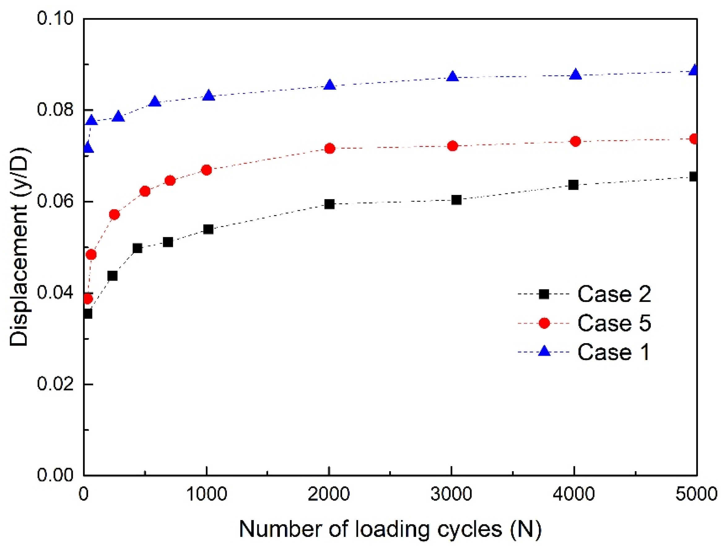
3.1. Pile Top Displacement

As for finned pile 2, Figure 5 shows the mud surface around the pile after eccentric wheel loading with an eccentricity of 5 mm. According to Figure 5, after loading with a 5 mm eccentric wheel, the mud surface around the pile suffered significant damage; after a few hours of rest after loading, the pile is covered with mud and distributed in a square shape with the fin plate as the diagonal. After removing the mud, it was found that much of the soil around the pile had been eroded, and the fin plate exposed about 28 mm of the soil, accounting for 28% of the fin length. In addition, there is a relatively uniform gap between the pile and soil, about 5 mm.
In this study, the software named MATLAB (Verison: 2022) was used to process the experimental results. MATLAB has the advantages of simple, easy-to-use, powerful numerical computing capabilities, rich graphics and visualization, and a wide range of application fields. Figure 6 shows the cumulative displacement changes at the pile top during the cyclic loading of a single pile and a finned pile, where y is the actual pile top displacement, D is the pile diameter, W is the width of the fin plate and N is the number of loading cycles. It can be observed from Figure 6 that under cyclic loading, the pile top displacement gradually increases for three types, and the pile top displacement of a single pile foundation is always greater than that of a finned pile foundation. The pile top displacement of finned pile 1 and finned pile 2 is relatively close in the initial loading stage, but as the number of cycles increases, the difference in pile top displacement between the two pile types gradually becomes apparent, that is, the pile with a smaller fin plate width has a relatively larger displacement. Therefore, it can be concluded that increasing the size of the fin plate can reduce the horizontal displacement of the pile foundation.
In order to quantify the variation in pile top displacement with the number of loading cycles, a mathematical model was obtained through regression analysis of the experimental results in Figure 6, which can be expressed as follows:
y D = A l n N + c
where A and c are the coefficients. The values of A and c for three different kinds of pile foundations in Figure 6 are shown in Table 3.

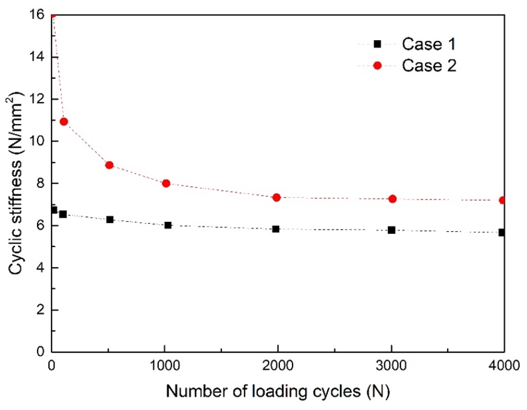
3.2. Cyclic Stiffness of Pile

Figure 7 shows the displacement load hysteresis curves of pile foundations under different load conditions. According to Figure 7, as the load increases, the amplitude of the hysteresis curve changes and the occupied area increases. When the load is small, the distribution of hysteresis curve tends to be vertical, while when the load is large, it tends to be horizontal. As the number of cycles increases, the hysteresis curve rotates clockwise, and this rotation phenomenon becomes more pronounced for operating conditions with larger loads.
Figure 8 shows the comparison results of the cyclic stiffness between finned pile 1 and a traditional single pile foundation, where the calculation method for cyclic stiffness is shown in Equation (2). As shown in Figure 8, the cyclic stiffness of the finned pile decreases significantly with the increase in the number of cycles, while the cyclic stiffness of the single pile foundation decreases very little. However, the cyclic stiffness of the finned pile is still higher than that of the ordinary single pile foundation in the end. This also proves that a finned pile foundation can improve the horizontal bearing capacity of piles to a certain extent compared to a traditional single pile foundation. In addition, the fewer the number of cycles, the greater the stiffness of the finned pile relative to the traditional single pile foundation.
K = F N , m a x F N , m i n ( y N , m a x y N , m i n ) D
where F N , m a x and F N , m i n are the maximum and minimum loads in the Nth cycle, respectively; y N , m a x and y N , m i n are the maximum and minimum displacements in the Nth cycle, respectively.
Based on the measured strains on both sides of the pile foundation, calculate the bending moment of the pile body at the corresponding depth using Equations (3)–(5).
Φ = ε t ε c D
M = E I Φ
I = π D 4 64 [ 1 d D 4 ]
where ε t ,     ε c are the tensile and compressive strains, respectively, on both sides of the pile in the loading direction, d is the pile diameter, E is the elastic modulus of the pile, and I is the section moment of inertia.
To better reflect the variation in cyclic stiffness (Ep) with the number of loading cycles (N), a mathematical model was fitted through a regression analysis of the experimental results in Figure 8, which can be expressed as follows:
E p = B l n N + j
where B and j are the coefficients. The values of B and j for case 1 and case 2 in Figure 8 are shown in Table 4.

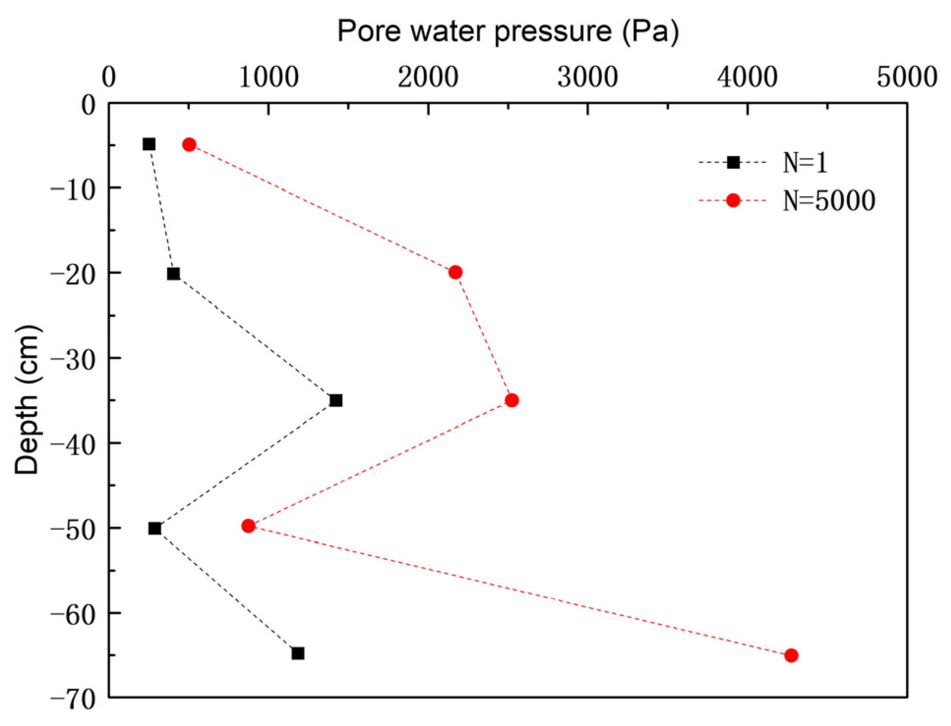
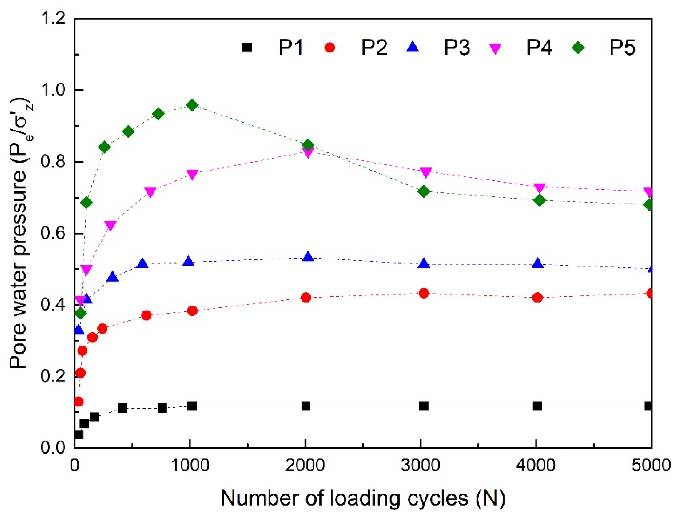
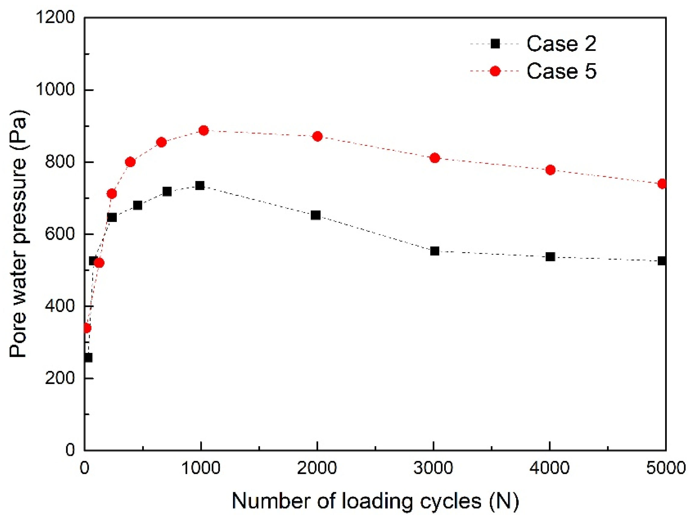
3.3. Pore Water Pressure Response around the Pile

Figure 9 shows the distribution of excess pore water pressure along the soil depth around the pile during the initial loading and 5000th loading. According to Figure 9, as the depth of the soil increases, the magnitude of the excess pore water pressure shows an S-shaped trend of first increasing, then decreasing, and then increasing again. Although the upper soil layer experiences the greatest disturbance, the excess pore water pressure is not the highest. In addition, the pore pressure is relatively small at a depth of 50 cm. This is because when the pile foundation undergoes displacement under horizontal load, the entire pile does not move in the same direction. The movement directions of the pile top and bottom are opposite, and there is a rotation center point with zero displacement in the pile body. The soil disturbance in this area is minimal, resulting in a small change in pore pressure. From the analysis of the variation law of pore pressure along the depth, the rotation center point of the above working conditions should be located at a depth of about 50 cm. After experiencing cyclic loading, the pore pressure along the depth direction of the soil has increased, but the overall distribution pattern has not changed. From the perspective of the amplitude of pore pressure changes before and after cyclic loading, the pore pressure change at the maximum depth position (depth 65 cm) is the most significant, exceeding 3000 Pa.
Figure 10 shows the variation in pore water pressure (expressed by p e / σ z ) at different depths with the number of cycles before and after cyclic loading. From Figure 10, it can be seen that the pore pressure at all depths has a cumulative trend, with P5 at a depth of 65 cm accumulating the most significantly. Its initial value is small, but the final value is the largest, while P1 at the shallowest 5 cm has the smallest cumulative amount and a smaller pore pressure value. In addition. It can be seen that the upper layer areas with larger disturbances, such as P1 and P2, have more obvious changes, followed by P3 and P5, while the smallest change is in P4. From the perspective of cumulative changes in pore pressure, it can be concluded that the soil disturbance in P4 area should be the smallest, and the rotation center of the pile should be located near this area. By analyzing P1 separately, it was found that after 1000 cycles, there was a significant decrease in the value. At N = 1000, the ratio of pore pressure to overlying soil pressure in this area was close to 1, indicating that this phenomenon may be caused by soil liquefaction.
To analyze the influence of pile type on the development of pore pressure, Figure 11 shows the variation in P1 pore pressure at 5 cm below the mud surface with different fin plate widths as a function of the number of cycles. It can be observed from Figure 11 that the pore pressure of finned pile 1 is generally smaller than that of finned pile 2. In the initial loading stage, the difference in pore pressure between the two is small. As the number of cycles increases, the difference in pore pressure gradually increases, and both show a decreasing trend after N = 1000. The maximum pore pressure value of finned pile 1 is 19% smaller than that of finned pile 2. Therefore, increasing the size of the fin plate can reduce the development of pore pressure inside the soil and further reduce the impact of pore water pressure on the bearing capacity of the soil.

4. Conclusions

This paper analyzes the failure mechanism of a finned pile foundation under horizontal cyclic loads by designing model tests of the pile–soil interaction. Based on the experimental results, the following conclusions are drawn:
(1)
Under cyclic loads, the presence of fin plates can reduce the horizontal displacement of the finned pile foundation, and when the width of the fin plate is reduced, the cumulative displacement of the finned pile foundation will increase. Therefore, in the design process, the horizontal displacement of the finned pile foundation can be reduced by increasing the width of the fin plate.
(2)
Compared with traditional single pile foundations, the cyclic stiffness attenuation of finned pile foundations is more severe, but the final equilibrium stiffness is still greater than that of traditional single pile foundations.
(3)
Increasing the size of the fin plate can reduce the response of pore water pressure in the soil of the finned pile foundation, and the pore pressure follows an S-shaped distribution along the soil depth, reaching its minimum value at the rotation center of the pile body and then increasing again.
(4)
The finned pile foundation has broad application prospects in future offshore wind turbine construction. This paper only explores the failure law of finned pile foundation under horizontal cyclic load through experimental methods. In the future, the artificial intelligence method should be combined to further analyze the bearing performance and design standards of finned pile foundation.
It should be noted that this study is only a preliminary study on the failure mechanism of a finned pile foundation under a horizontal cyclic load, and the influence of initial parameters of the tubular pile on the horizontal bearing performance of the finned pile foundation has not been considered. Further study is needed to assess the aforementioned influences.

Author Contributions

Conceptualization, L.D.; Investigation, L.D., M.F., B.Z., H.W., H.L., G.T. and B.G.; Writing—original draft, L.D.; Writing—review & editing, B.Z.; Supervision, B.G. All authors have read and agreed to the published version of the manuscript.

Funding

This research was funded by State Key Laboratory of Bridge Engineering Structural Dynamics and Key Laboratory of Bridge Earthquake Resistance Technology, Ministry of Communications. Also, this research was supported by the Fund of National Natural Science Foundation of China (Grant No: 52108268).

Data Availability Statement

All data, models, and code generated or used during the study appear in the submitted article.

Conflicts of Interest

Authors Lunliang Duan, Haiming Liu, Guangwu Tang, Haicui Wang and Bo Geng were employed by the company China Merchants Chongqing Communications Technology Research and Design Institute Co., Ltd. The remaining authors declare that the research was conducted in the absence of any commercial or financial relationships that could be construed as a potential conflict of interest.

References

  1. Dennis, Y.C.L.; Yuan, Y. Wind energy development and its environmental impact: A review. Renew. Sustain. Energy Rev. 2012, 16, 1031–1039. [Google Scholar]
  2. International Energy Agency (IEA). Offshore Wind Outlook 2019: Offshore wind Outlook to 2040; International Energy Agency (IEA): Paris, France, 2020. [Google Scholar]
  3. Cerfontaine, B.; White, D.; Kwa, K.; Gourvenec, S.; Knappett, J.; Brown, M. Anchor geotechnics for floating offshore wind: Current technologies and future innovations. Ocean Eng. 2023, 279, 114327. [Google Scholar] [CrossRef]
  4. Chen, J.; Gilbert, R.B.; Choo, Y.S.; Marshall, P.W.; Murff, J.D. Two-dimensional lower bound analysis of offshore pile foundation systems. Int. J. Numer. Anal. Methods Geomech. 2016, 40, 1321–1338. [Google Scholar] [CrossRef]
  5. He, R.; Zhang, J.; Zheng, J. Vertical dynamic interaction factors for offshore thin-walled pipe piles. Comput. Geotech. 2022, 145, 104656. [Google Scholar] [CrossRef]
  6. Zheng, C.; Lin, H.; Cao, G.; Luan, L. Horizontal dynamic response of offshore large-diameter pipe piles. Ocean Eng. 2023, 272, 113797. [Google Scholar] [CrossRef]
  7. Xu, D.S.; Xu, X.Y.; Li, W.; Fatahi, B. Field experiments on laterally loaded piles for an offshore wind farm. Mar. Struct. 2020, 69, 102684. [Google Scholar] [CrossRef]
  8. Chen, L.; Li, J.; Wu, W.; Liu, H.; Yao, Y.; Zhang, P. New method to calculate the kinematic response of offshore pipe piles under seismic S-waves. Soil Dyn. Earthq. Eng. 2023, 165, 107651. [Google Scholar] [CrossRef]
  9. Hu, T.; Dai, G.; Wan, Z.; Fang, B.; Chen, X. Full-scale tests on the grouting effectiveness of offshore bored piles with various bearing strata. Appl. Ocean Res. 2023, 141, 103791. [Google Scholar] [CrossRef]
  10. Xiao, S.; Lin, K.; Liu, H.; Zhou, A. Performance analysis of monopile-supported wind turbines subjected to wind and operation loads. Renew. Energy 2021, 179, 842–858. [Google Scholar] [CrossRef]
  11. Li, W.; Zhao, S.J.; Zhou, Y.; Xu, X.Y. 1g-model test of large diameter monopile with wings for offshore wind turbine. China Civ. Eng. J. 2013, 46, 124–132. [Google Scholar]
  12. Li, W.; Hu, B.; Li, B.; Xu, X.Y.; Xiong, G.; Zhao, S.J. Centrifuge model tests on horizontal bearing capacity of a large diameter pile with wings. Chin. J. Rock Mech. Eng. 2015, 34, 831–837. [Google Scholar]
  13. Chen, C.M.; He, J.X.; Su, X.D.; Wang, X.P.; Huang, W.L. Analysis of calculation method for horizontal bearing capacity of wing-monopile. Hydro-Sci. Eng. 2018, 4, 1–8. [Google Scholar]
  14. Nasr, A.M. Experimental and theoretical studies of laterally loaded finned piles in sand. Can. Geotech. J. 2014, 51, 381–393. [Google Scholar] [CrossRef]
  15. Abongo, K.; Gu, J.; Pervizpour, M.; Quiel, S.; Pamukcu, S. Parametric lab-scale testing and numerical simulation of finned monopiles under directional loading. Ocean Eng. 2022, 259, 111871. [Google Scholar] [CrossRef]
  16. Pei, T.; Qiu, T. A Numerical Investigation of Laterally Loaded Steel Fin Pile Foundation in Sand. Int. J. Geomech. 2022, 22, 04022102. [Google Scholar] [CrossRef]
  17. Sakr, M.A.; Azzam, W.R.; Wahba, M.A. Model study on the performance of single-finned piles in clay under lateral load. Arab. J. Geosci. 2020, 13, 172. [Google Scholar] [CrossRef]
  18. Hu, Y.Z.; Lu, Z.A.; Zhai, Q.; Zhang, Y.Q. Discussion on p-y curve of large diameter winged pile in soft clay. Water Resour. Hydro-Power Eng. 2018, 49, 143–152. [Google Scholar]
  19. Bienen, B.; Dührkop, J.; Grabe, J.; Randolph, M.F.; White, D.J. Response of Piles with Wings to Monotonic and Cyclic Lateral Loading in Sand. J. Geotech. Geoenviron. Eng. 2012, 138, 364–375. [Google Scholar] [CrossRef]
  20. Peng, J.R.; Rouainia, M.; Clarke, B.G. Finite element analysis of laterally loaded fin piles. Comput. Struct. 2010, 88, 1239–1247. [Google Scholar] [CrossRef]
  21. Albusoda, B.S.; Al-Saadi, A.F.; Jasim, A.F. An experimental study and numerical modeling of laterally loaded regular and finned pile foundations in sandy soils. Comput. Geotech. 2018, 102, 102–110. [Google Scholar] [CrossRef]
  22. Moein, K.; Mir, A.H.; Alireza, S.A. Performance of finned piles as a protection for a 2*2 group pile subjected to liquefaction-induced lateral spreading: A shake table investigation. Soil Dyn. Earthq. Eng. 2023, 170, 107915. [Google Scholar]
  23. Qin, H.Y.; Hung, C.Y.; Wang, H.; Zhang, J. Response of laterally loaded finned piles in sand. Acta Geotech. 2023, 19, 1765–1786. [Google Scholar] [CrossRef]
  24. Naggar, M.H.E.; Bentley, K.J. Dynamic analysis for laterally loaded piles and dynamic p-y curves. Can. Geotech. J. 2000, 37, 1166–1183. [Google Scholar] [CrossRef]
Figure 1. The size of model pile (Unit: mm).
Buildings 14 02814 g001
Figure 2. The grading curve of kaolin soil.
Buildings 14 02814 g002
Figure 3. Sketch of sensor layout.
Buildings 14 02814 g003
Figure 4. Sketch of loading device.
Buildings 14 02814 g004
Figure 5. Damage of mud surface around the pile after loading with an eccentricity of 10 mm (Finned pile 2): (a) mud around the pile after loading; (b) exposure depth of side fins after removing mud.
Buildings 14 02814 g005
Figure 6. Comparison of pile top displacement (Eccentricity is 5 mm).
Buildings 14 02814 g006
Figure 7. Comparison of pile top displacement: (a) case 2; (b) case 3; (c) case 4.
Buildings 14 02814 g007
Figure 8. Comparison of cyclic stiffness between finned piles and single piles.
Buildings 14 02814 g008
Figure 9. The variation in pore pressure with depth before and after cyclic loading (case 2).
Buildings 14 02814 g009
Figure 10. The variation of pore pressure at different depths with the number of cyclic loading (case 2).
Buildings 14 02814 g010
Figure 11. Comparison of pore water pressure development process for different pile types.
Buildings 14 02814 g011
Table 1. The properties of model soil.
ParametersValuesUnits
Median size (d50)0.0046mm
Relative density (Gs)2.57-
Poisson’s ratio (us)0.47-
Liquid limit (wI)43.07-
Plastic limit (wp)24.70-
Plasticity index (Ip)18.37-
Moisture content (w)35-
Volume-weight (r)17.3kN/m3
Cohesive force (c)15kPa
Internal friction angle (α)20°
Table 2. Information of test cases.
CasePile TypeFin WidthFin LengthLoad TypeLoading Eccentricity
Case 1Single pile--Cyclic loads5 mm
Case 2Fined Pile 11 D2 DCyclic loads5 mm
Case 3Fined Pile 11 D2 DCyclic loads10 mm
Case 4Fined Pile 11 D2 DCyclic loads17 mm
Case 5Fined Pile 20.5 D2 DCyclic loads5 mm
Case 6Fined Pile 20.5 D2 DCyclic loads10 mm
Case 7Fined Pile 20.5 D2 DStatic loads-
Table 3. The values of coefficients A and c.
Type of Pile FoundationAc
Finned pile foundation (W = 1 D)0.00610.0131
Finned pile foundation (W = 0.5 D)0.00670.0193
Monopile foundation0.00310.0625
Table 4. The values of coefficients B and j.
CaseBj
Case 10.27.4
Case 21.519.0
Disclaimer/Publisher’s Note: The statements, opinions and data contained in all publications are solely those of the individual author(s) and contributor(s) and not of MDPI and/or the editor(s). MDPI and/or the editor(s) disclaim responsibility for any injury to people or property resulting from any ideas, methods, instructions or products referred to in the content.

