Abstract
This paper investigates the structural performance of flat double-layer grids with various constitutive units, addressing a notable gap in the literature on diverse geometries. Six common types of flat double-layer grids are selected to provide a comprehensive comparison to understand their structural performance. Parametric models are built using Rhino and Grasshopper plugins. Single- and multi-objective optimization processes are conducted on the considered models to evaluate structural mass and maximum deflection. The number of constitutive units, the structural depth, and the cross-section diameter of the members are selected as design variables. The analysis reveals that the semi-octahedron upon square-grid configuration excels in minimizing structural mass and deflection. Furthermore, models lacking a full pyramid form exhibit higher deflections. Sensitivity analyses disclose the critical influence of the design variables, particularly highlighting the sensitivity of structural mass to the number of constitutive units and cross-section diameter. These findings offer valuable insights and practical design considerations for optimizing double-layer grid space structures.
1. Introduction
The increasing demand for constructing complex structures has driven the adoption of space structures, which are renowned for their innovative architectural forms and structural efficiency [1]. These structures are truss-like constructions composed of interlocking lightweight elements arranged in specific geometric patterns, typically used to span large areas with minimal supporting columns. Space structures are particularly favored in architectural applications due to their excellent structural performance and esthetic appeal, especially in free-form configurations [2,3,4,5]. Despite extensive research on specific aspects of double-layer grids, the literature lacks comprehensive comparisons that evaluate the structural performance of these grids across various constitutive units, structural depths, and cross-section diameters. This study aims to fill this gap by conducting a detailed comparative analysis and sensitivity assessment of six common types of flat double-layer grid space structures to enhance understanding of their structural behavior.
The selection of appropriate materials is critical in structural design, as materials must provide sufficient strength to withstand both tensile and compressive forces [6]. Common materials used in space structures include steel, aluminum, and timber. Space structures can be categorized into single-, double-, or triple-layer flat grids, as well as braced-barrel vaults and domes, with double-layer grids being the most prevalent in applications such as terminals, sports complexes, domes, and hangars [7]. Over the past few decades, extensive research has been conducted on the performance of double-layer grid structures, focusing either on specific components of the system [8,9] or the overall structural behavior [10,11]. For instance, composite double-layer grids have been shown to improve structural reliability and reduce the probability of progressive collapse in bridge decks compared to conventional reinforced concrete slabs [10]. Additionally, the use of double-layer space structures as vertical load-resisting elements in super-tall buildings has been explored, highlighting their potential advantages [11].
Proper connections between elements are essential for achieving reliable performance in double-layer grid structures. Previous studies have evaluated the effects of different joints, such as spherical joints [12], plate joints [13], and hollow section joints [14], and reported their successful load-transferring behavior. However, the probability of failure in joints containing multiple members under accidental loads remains high, as demonstrated by Tian et al. [15,16]. Furthermore, the work of Lee and Makowski [17] highlighted the key roles of structural depth, element size, and the number of supports in stress distribution and overall cost, providing essential insights for optimization strategies.
Structural optimization is another critical area of study, as it aims to achieve economic designs by minimizing weight and cost [18,19]. Previous research has focused on optimizing various parameters, such as the number of elements and nodes, to facilitate mass production of repeated components [20,21]. Salajegheh et al. [22] used a genetic algorithm to determine the optimal shape for space structures by selecting joint locations and cross-sectional areas as design variables, considering structural weight as the cost function. Other studies have explored different optimization strategies, emphasizing the importance of factors like structural depth, element size, and the number of supports on stress distribution and total cost [23,24,25,26].
Several research studies have been conducted on the effectiveness of double-layer grids’ parameters during the last decades. Lee and Makowski [17] and Agerskov [27] performed comparative studies to assess the stress distribution in structural elements of different configurations of flat double-layer grids. The results indicated that the optimum stress distribution results in lower material consumption depending on the number of nodes and the position of the supports. Grigorian [28] investigated the usefulness of truss elements in a simple space structure based on two main criteria of maximum structural deflection and failure mechanism. In 2017, Surzhan et al. [29] evaluated the material consumption for different structural depth-to-span under service and ultimate limit states. They showed that the structural depth is inversely proportional to the material consumption. The space structure in their studies was formed based on a semi-octahedron upon a square-grid pattern. A similar investigation was conducted in 2020 by Alpatov [30] to highlight the effects of structural depth and the number of nodes in material consumption. In another study, Alpatov [31] investigated the influence of rod numbers attaching in a joint on their performance and manufacturing cost.
Despite these significant contributions to evaluating the influencing parameters of each double-layer grid, limited investigations have been conducted on the comparison of different forms of these structures, and a comparative analysis of different configurations seems to be necessary. To address this critical gap, this paper presents a comprehensive analysis of six widely used flat double-layer grid configurations, each varying in constitutive units. Advanced parametric modeling is employed using Rhino environment and Grasshopper plugins, and both single and multi-objective optimization processes are conducted to evaluate structural mass and maximum deflection. A detailed sensitivity analysis is also performed to examine the influence of design variables such as the number of constitutive units, structural depth, and cross-section diameter on structural performance. The findings from this study offer practical guidelines for the optimal design of double-layer grid space structures. This paper is organized as follows: Section 2 outlines the methodology, Section 3 describes the simulation and modeling processes, and Section 4 and Section 5 present the results and conclusions, respectively.
2. Methodology
2.1. Double-Layer Space Structure
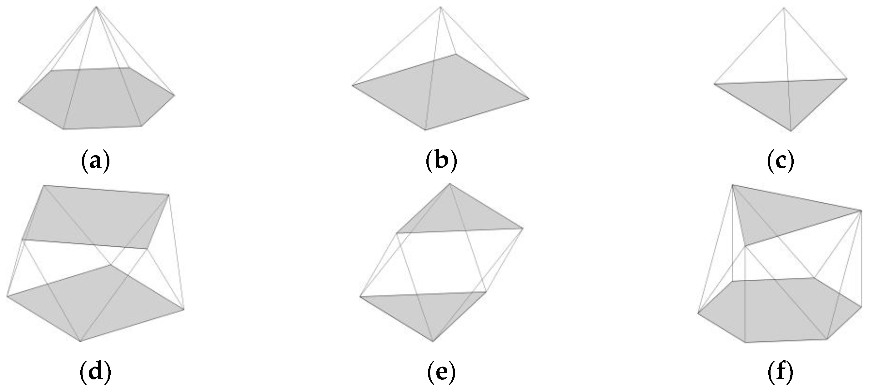
Double-layer space structures consist of two parallel layers of chord members interconnected through diagonal elements. These structures are generally divided into planar and curved grids. The planar double-layer space structures, also known as space frames, are the most common type due to their adaptability and simpler erection process compared to curved types. Over the past few decades, various space frames with different geometrical forms of constitutive units have been investigated, and their performance has been evaluated [32,33,34,35]. Figure 1 shows the constitutive units of six popular types of flat double-layer space structures [36], whose structural performance will be evaluated in this paper.
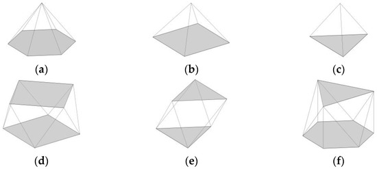
Figure 1.
Various geometrical forms of constitutive units for planar double-layer space structures: (a) hexagonal pyramid upon a honeycomb grid; (b) semi-octahedron upon a square grid; (c) tetrahedron upon a triangular grid; (d) two square grids at a 45° rotational angle; (e) two counter-running triangular grids; (f) triangular grid above the hexagonal grid.
2.2. Optimization Process
The optimization process is defined as a procedure for identifying the best possible solution among all available alternatives. This process is typically carried out by minimizing a cost function f(x) while considering constraints relevant to the optimization problem.
2.2.1. Cost Function
Total cost and the assurance of structural stability are the main features affecting the choice of space structures in a project. Structural mass directly influences the overall cost, while deflection control ensures confidence in the structural stability. This paper adopts two approaches to achieve these objectives. The first approach treats both structural mass and deflection as cost functions, allowing for a balanced optimization between cost and stability. The second approach selects structural mass as the sole cost function, with deflection constraints adhering to the recommended limitations from design codes, ensuring that stability is maintained within acceptable limits.
2.2.2. Constraints
The constraints governing the optimization process can be divided into two types: inequality constraints and equality constraints . The general forms of these constraints are given as follows:
where X is the optimization variable, and L and U are the boundary conditions. These constraints can be either behavioral or geometric. Behavioral constraints assess the structural capacity concerning the required demand recommended by the provision [37], while geometric constraints provide a reasonable range for each design variable. In this study, the axial capacity of the structural members, as well as their buckling capacity, are defined as behavioral constraints. The geometric constraints considered are listed in Table 1. These geometric constraints are applied to the design variables, including the rod diameter as the cross-sectional characteristic of the elements, the number of constitutive units in the entire space structure, and the structural depth (the distance between the lower and upper layers).

Table 1.
Geometric constraints of the considered design variables of this study.
2.2.3. Genetic Algorithm
The genetic algorithm (GA) is a metaheuristic optimization technique that follows the natural selection process. The developed form of the algorithm was presented by David E. Goldberg [38].
During the optimization process, an initial population with specific properties is generated and randomly distributed within the search space of the variables. This initial population is referred to as phenotypes, and each individual within the population is called a chromosome. In each iteration, the cost function of every chromosome is evaluated, and those with lower cost functions are retained for the next iteration. Their properties are revised based on recombination or random mutation to generate subsequent generations. The remaining chromosomes are replaced by new ones. This iterative process continues until the desired number of iterations is reached.
3. Numerical Simulations
To assess the structural performance of flat double-layer grids, six types of structures with different constitutive units are considered in this study. These include a hexagonal pyramid upon a honeycomb grid, a semi-octahedron upon a square grid, a tetrahedron upon a triangular grid, two square grids at a 45° rotational angle, two counter-running triangular grids, and a triangular grid above a hexagonal grid. For simplicity, these structures are referred to as M1 to M6, respectively. Plan and perspective views of the considered models are shown in Figure 2.
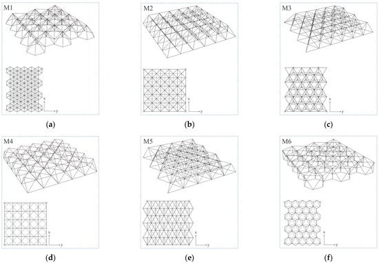
Figure 2.
Plan and perspective view for (a) M1, hexagonal pyramid upon honeycomb grid; (b) M2, semi-octahedron upon square grid; (c) M3, tetrahedron upon triangular grid; (d) M4, two square grids in 45° rotational angle; (e) M5, two counter-running triangular grids; and (f) M6, triangular grid above the hexagonal grid.
Parametric modeling for these structures is developed using Rhino 7.0 software and the Grasshopper plugin. The 3D models are created with a length of 10 m in the x-direction. Due to the geometric forms of the constitutive units, the structural length in the y-direction cannot be fixed at 10 m for all models. Therefore, the models are created twice: once with the maximum possible units in the y-direction to provide a corresponding length less than 10 m, and once with the minimum possible units in the y-direction to achieve a length greater than 10 m. This approach covers both possibilities for creating a plan dimension of 10 m × 10 m. After finalizing the modeling phase, the Karamba3D plugin is utilized for defining structural characteristics and conducting static analyses. For this purpose, four simple supports are assumed at each corner of the plan to prevent structural movements, as indicated by the circles in the plan view in Figure 2. The structural members are defined using the Line to Beam command in the software, and both ends are released to provide a pinned connection. A rod cross-section is assigned to the members using the cross-section option. For industrialization purposes, the rod diameter is kept the same for all elements. S355 steel material, with an elastic modulus of 210 GPa and yield strength of 355 MPa, is used for the rods. The depth, number of units in the x-direction, and the cross-section of the members are selected as variables.
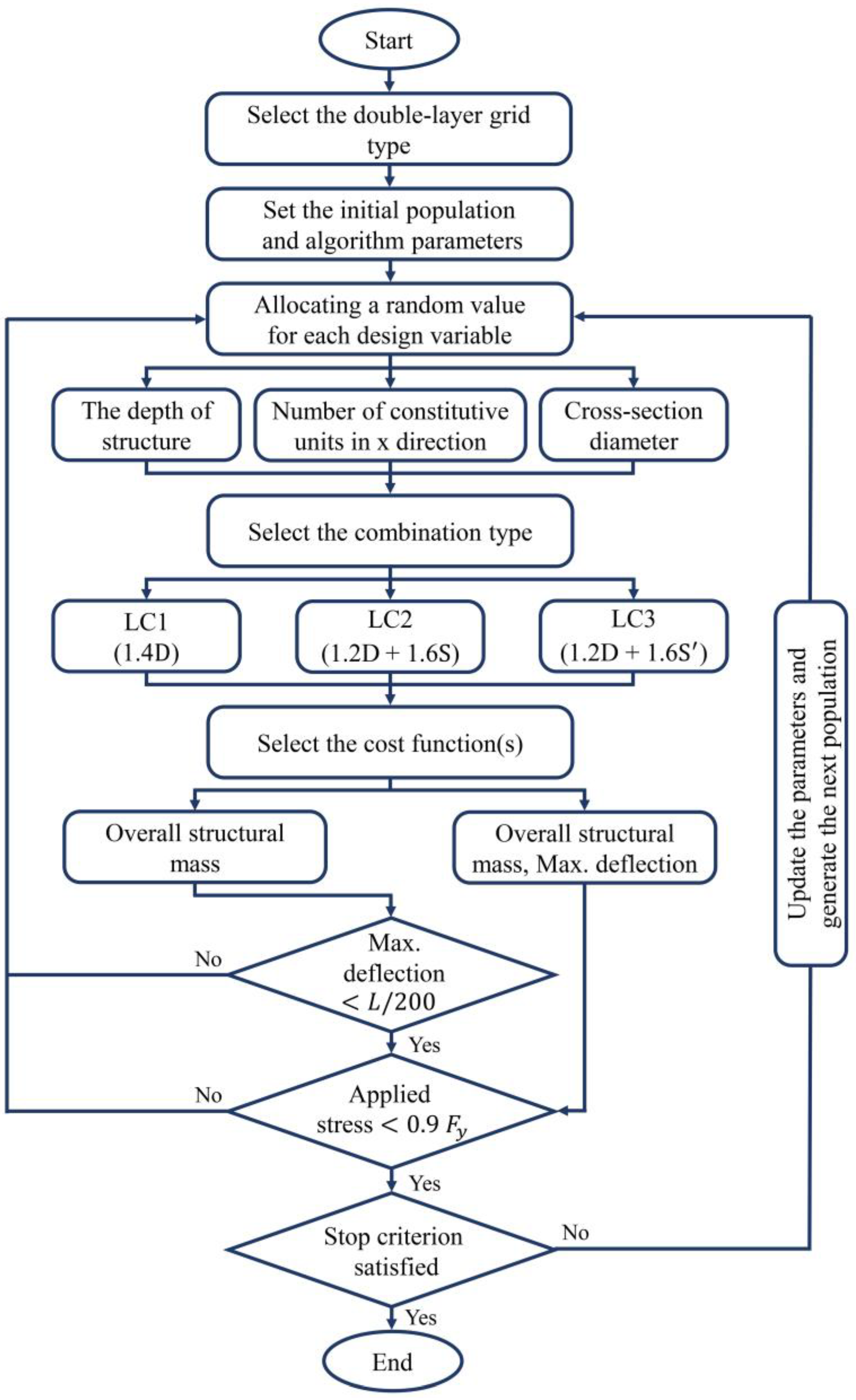
Three load combinations, including dead load (D), balanced snow load (S), and unbalanced snow load (S’), are considered based on the Iranian national code, part 6 [39], as depicted in the flowchart in Figure 3. An unfactored extra dead load for the covering is assumed to be 0.5 kN/m2, which is added to the structural weight, and the unfactored snow load is 1.2 kN/m2.
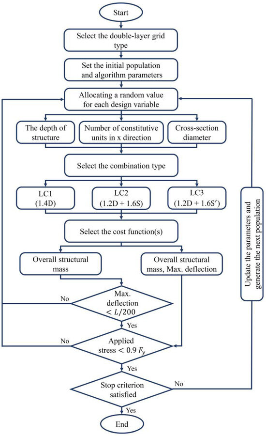
Figure 3.
The simulation and optimization process.
The optimization process of the models is conducted using the Octopus plugin and Galapagos components for multi- and single-objective optimizations. The considered design variables, along with their lower- and upper-bound limits, are provided in Table 1. The cost functions for multi-objective optimization are the overall mass and maximum deflection of the structure, while for single-objective optimization, the cost function is the structural mass, with the maximum deflection defined as a constraint limited to L/200 [40] (where L is the span of the structure). For both the single- and multi-objective optimizations, the population number is set to 100. The maximum number of iterations is set to 50 for the multi-objective optimization and 5 for the single-objective optimization, which serves as the termination criterion. Through trial and error, it was determined that higher iterations had minimal impact on the optimal results.
The optimization process is illustrated in the flowchart in Figure 3. The process begins with selecting the double-layer grid type and setting the optimization algorithm parameters. The values of each design variable are allocated randomly according to the algorithm’s specific procedure. The chosen load combination is then applied to the structure, and a static analysis is conducted using the software. Depending on the optimization type, either single- or multi-objective, the cost function(s) is (are) evaluated, and the relevant constraints are assessed. Finally, the stop criterion is checked by the software; if the iteration reaches its maximum value, the optimal parameters of the variables, as well as the corresponding cost function(s), are displayed.
4. Results and Discussion
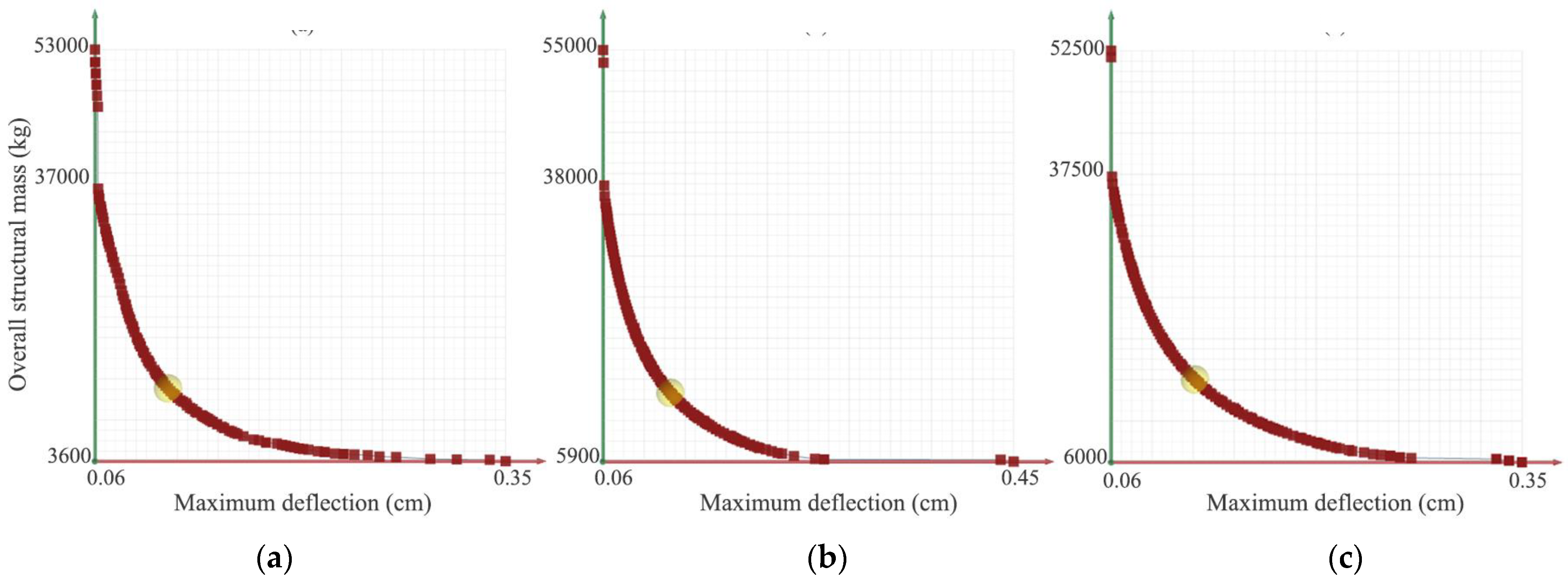
In this section, the optimal design parameters for double-layer grids with various constitutive units, based on multi-objective optimization and the design variable boundaries outlined in Table 1, are computed and presented. Figure 4 illustrates the Pareto front of optimal solutions for the M2 model within the defined search space. The vertical axis represents the overall structural mass, while the horizontal axis corresponds to the maximum deflection. The points on the Pareto front denote a set of superior solutions compared to the other available options. Solutions located on the hypothetical bisector represent choices with balanced weights for both cost functions. As each axis is approached, the corresponding cost function’s weight increases, concentrating the optimization process on minimizing that cost function.
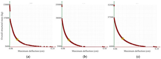
Figure 4.
The Pareto front of optimal solutions in the M2 model under (a) LC1, (b) LC2, and (c) LC3 load combinations.
Similar results were obtained for the other models considered in this study, though they are not included here to limit the number of charts. For a more effective comparison, solutions situated on the hypothetical bisector have been selected for all considered models, and their results are presented in Table 2. This Table lists the optimum values of the variables as well as their corresponding cost functions for the different models. For the M1, M3, M5, and M6 models, where the spans in the y-direction could not be fixed at 10 m, both cases—where the span is either less than or greater than 10 m—are provided, as previously discussed in Section 3.
Table 2.
Multi-objective optimization results for all considered models.
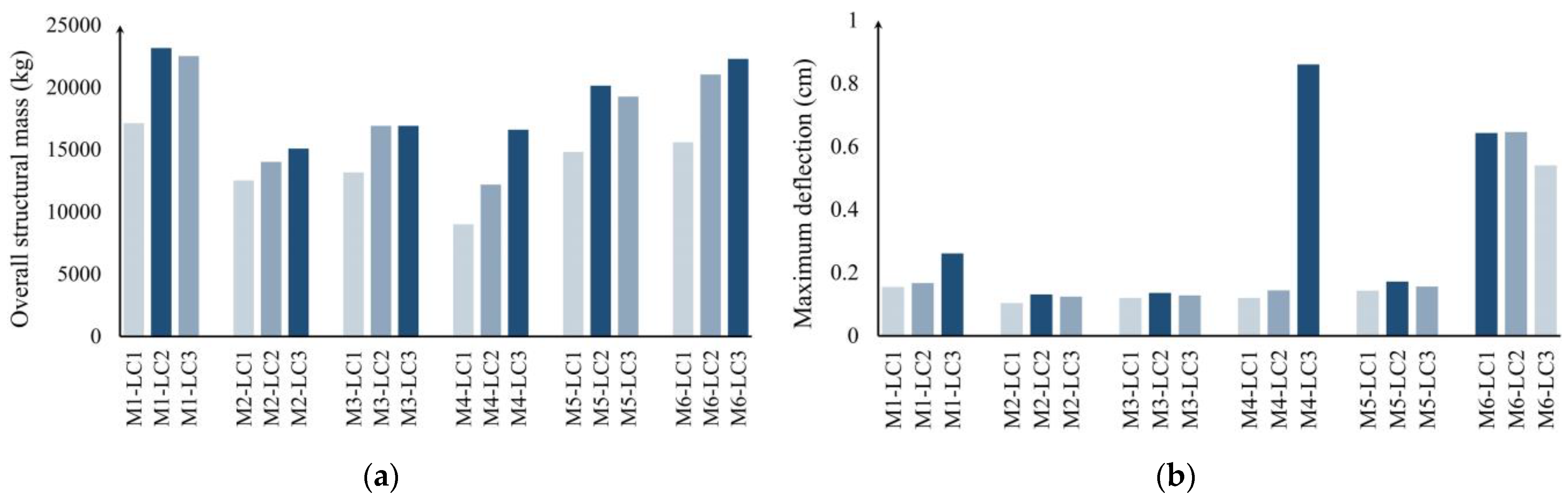
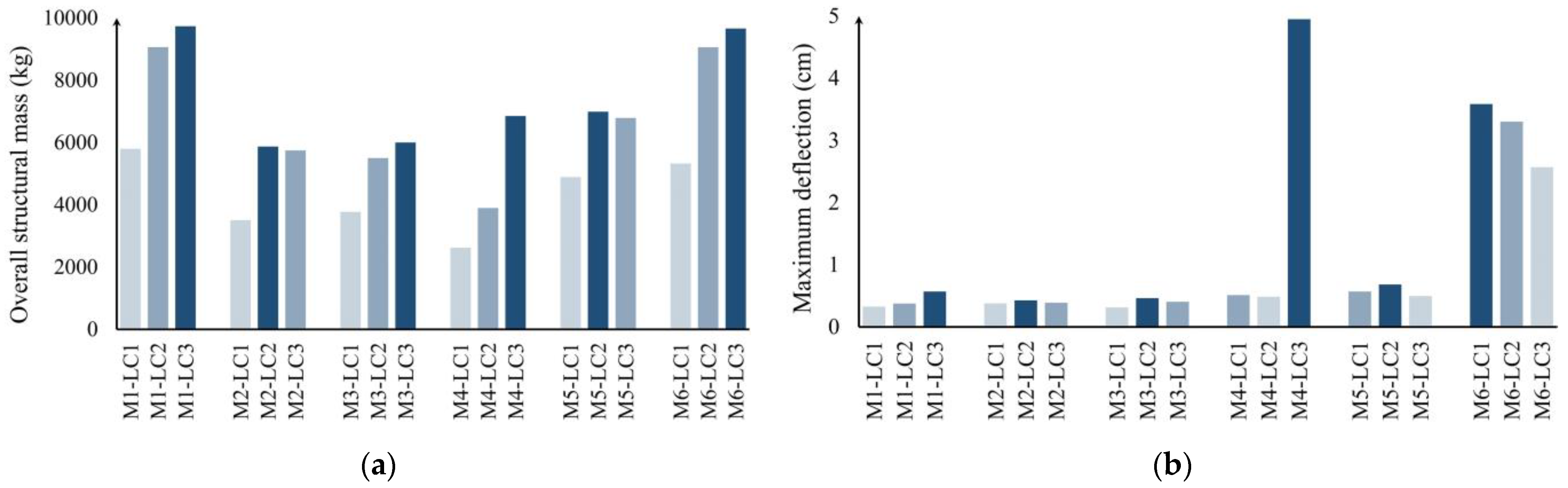
According to the results presented in Table 2, the dominant load combination varies with changes in the pattern of constitutive units. Specifically, LC2 is critical for models M1, M3, and M5, whereas LC3 is dominant in models M2, M4, and M6. It is evident that the cost functions increase when the number of constitutive units is adjusted to provide a span greater than 10 m. For a clearer comparison, the results from Table 2 are visualized in Figure 5. However, due to the unreasonable values observed in models with spans less than 10 m, their results are excluded from Figure 5. The critical load combinations for different models are highlighted in dark blue within Figure 5.
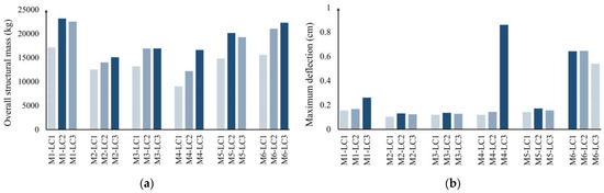
Figure 5.
The optimum: (a) overall structural mass and (b) maximum deflection for all the studied models under different load combinations.
As shown in Figure 5a, the minimum overall structural mass is associated with the M2 model, with a value of 15,093.9 kg, while the M1 model has the maximum structural mass. Figure 5b compares the maximum deflection across different models; here, the M1 model exhibits the lowest deflection. It is also noted that the deflections in the M3 and M6 models are larger than in the other models studied. This is due to the fact that the constitutive units in these models do not form a pyramid, a geometric shape known for its stability. This aspect will be further discussed later in this section.
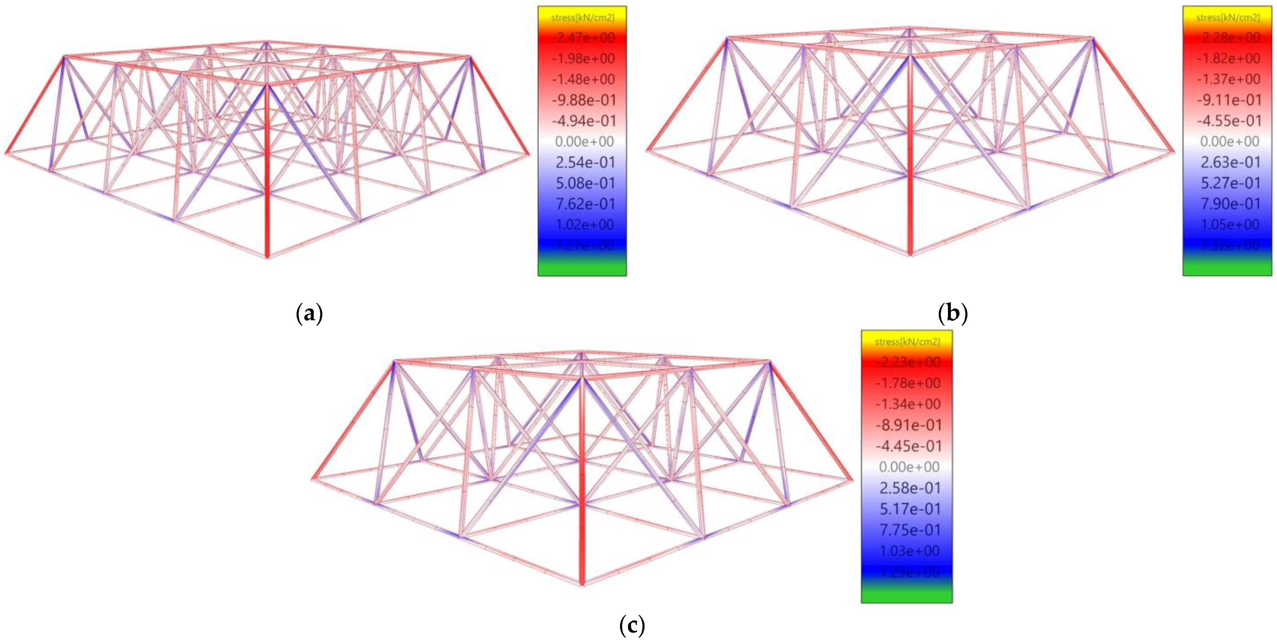
Figure 6 illustrates the axial stress distributions of the M2 model under the three considered load combinations. The contour beside each model is colored from dark blue to dark red, representing tension and compression axial stresses, respectively. As observed, the distribution is nearly identical under different load combinations, with higher stress concentrations near the support positions.
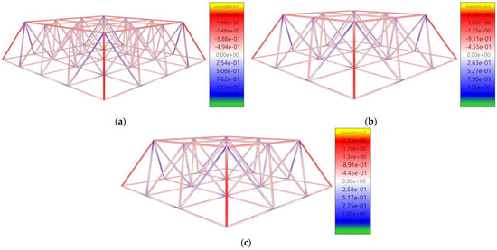
Figure 6.
Axial stress distribution in model M2 under (a) LC1, (b) LC2, and (c) LC3 load combinations.
To better understand the effects of the variables, the considered models were re-optimized based on a single-cost function focused on overall structural mass, which is more significant from an economic perspective. Unlike the previous process, deflection was excluded as a cost function and instead constrained to L/200, a more practical limit. The results of this optimization are presented in Table 3.
Table 3.
Single-objective optimization results for all considered models (L/200 equals 5 cm).
According to Table 3, the overall structural mass is reduced compared to the corresponding results in Table 2. Similar to the earlier findings, the critical load combination varies across different models. The results from Table 3 are also visualized in Figure 7 for ease of comparison. As before, the critical load combinations are highlighted in dark blue. Analysis of these results underscores the superiority of the M2 model compared to the other five models. Notably, the maximum deflection values in models M4 and M6 are higher than in the other models, likely due to the absence of a full pyramid form in their constitutive units. In summary, the M2 model appears to excel in both overall structural mass and maximum deflection.

Figure 7.
Single-objective optimization outcomes: (a) the optimum overall structural mass, (b) the corresponding maximum deflection for all the studied models under different load combinations.
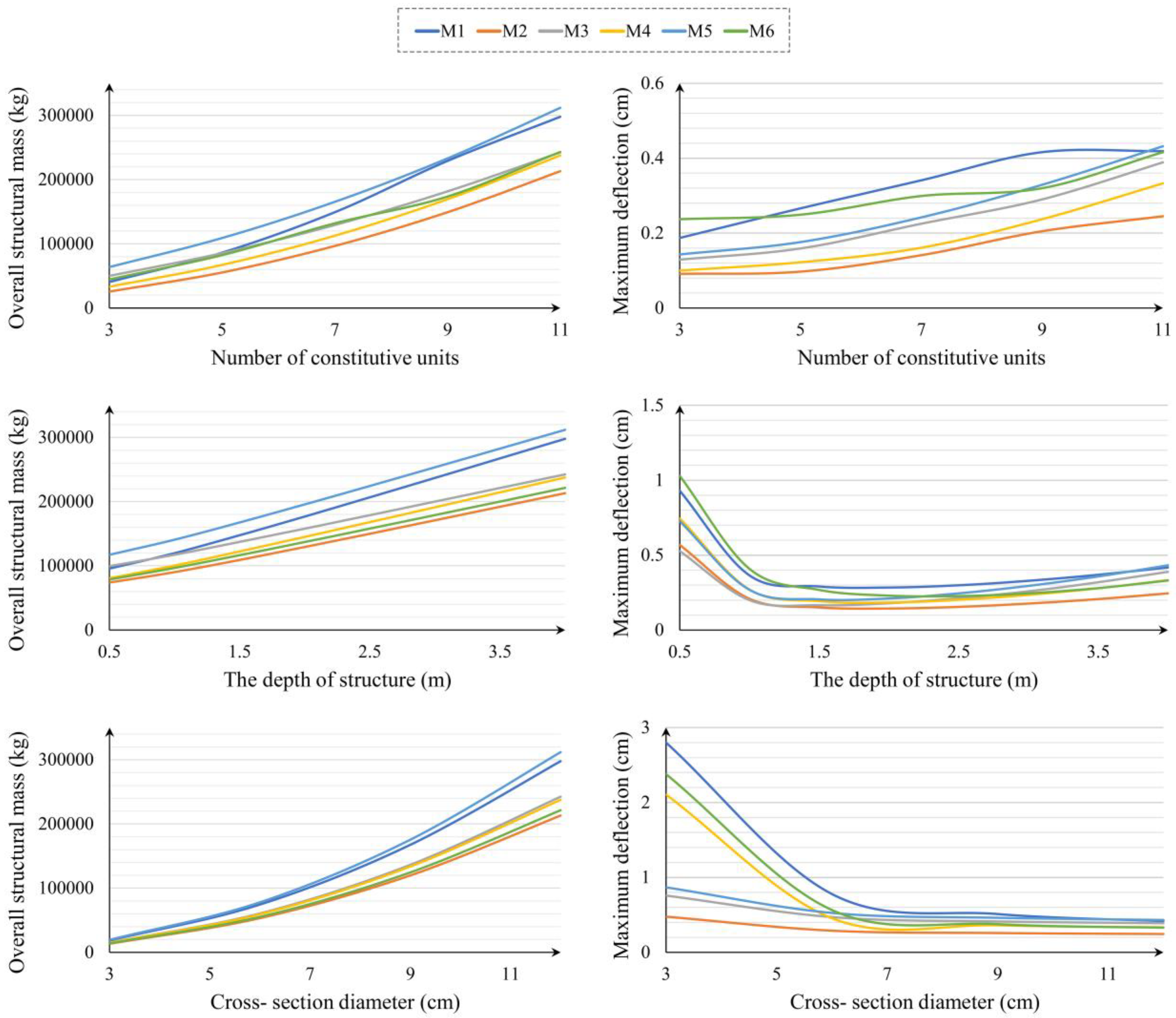
A sensitivity analysis was conducted to investigate the impact of each variable on the cost functions. For this analysis, each variable’s value was independently altered while keeping the other parameters constant, allowing us to observe its influence on overall structural mass and maximum deflection. To avoid unstable conditions across different models, the constant variables were set to their upper limits (i.e., structural depth, cross-section diameter, and the number of constitutive units were assumed to be 4 m, 15 cm, and 11, respectively). The ranges of alteration for structural depth, cross-section diameter, and the number of constitutive units were within the intervals of [0.5 m–4 m], [3 cm–12 cm], and [3–11], respectively. The goal of this analysis was to clearly understand the role each variable plays in structural performance.
The results of this analysis are presented in Figure 8. As shown, increasing the number of constitutive units, structural depth, and cross-section diameter leads to an increase in structural mass. However, the rate of increase varies, with structural mass being more sensitive to the number of constitutive units and cross-section diameter than to structural depth. Unlike the other variables, the effect of cross-section diameter on mass is non-linear, with a significantly greater impact at larger diameters. This trend is consistent across all models. This observation is also reflected in the results of Table 2, where the optimization process tends to minimize the number of constitutive units, utilize intermediate diameters, and meet additional requirements by increasing the structural depth.
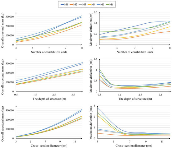
Figure 8.
The sensitivity analysis result for the considered variables of this study.
The influence of each variable on maximum structural deflection is also illustrated in Figure 8. As shown, an increase in the number of constitutive units proportionally increases deflection. In contrast, the effects of depth and cross-section diameter exhibit an inverse trend, where increases in these variables lead to a reduction in deflection. The beneficial impact of these two variables on structural deflection is more pronounced at lower values, with diminishing returns as their values continue to increase. The effects of the number of constitutive units and cross-section diameter on structural deflection are highly dependent on the selected type of double-layer grid, whereas the impact of depth remains relatively consistent across different grid types.
5. Conclusions
This paper investigates the performance of flat double-layer space structures, focusing on two key factors: overall structural mass and deflection. To address a significant gap in the comparative analysis of different types of double-layer grids, six diverse configurations were parametrically simulated, varying in constitutive units, structural depth, and cross-section diameters. Both the single- and multi-objective optimization processes were performed to assess structural mass and deflection. Additionally, a sensitivity analysis was conducted to understand the impact of each variable on structural mass and maximum deflection. The main findings are summarized as follows:
- The superiority of the semi-octahedron configuration over the square grid configuration in minimizing both structural mass and maximum deflection is clearly demonstrated. Specifically, the multi-objective optimization results show that the semi-octahedron configuration achieves an overall structural mass of approximately 15,093 kg and a maximum deflection of 0.124 cm. In contrast, under the single-objective optimization process, the overall structural mass is reduced to 5873 kg, with a corresponding maximum deflection of 0.428 cm.
- The critical load combination affecting optimization results varies depending on the pattern of constitutive units.
- Increasing the number of constitutive units, structural depth, and cross-section diameter leads to an increase in structural mass. However, the rate of increase is more sensitive to the number of constitutive units and cross-section diameter than to structural depth.
- Unlike structural depth and cross-section diameter, an increase in the number of constitutive units results in higher maximum deflection.
- The effects of the number of constitutive units and cross-section diameter on structural deflection are highly dependent on the selected type of double-layer grid.
- Based on the analysis of all models, it was found that selecting a structural depth within the range of 1 m to 1.5 m and choosing a cross-section diameter between 6 cm and 7 cm result in optimal structural deflection. These quantitative insights provide a clear direction for designers in selecting the most effective configuration and design parameters.
The comparative assessment and sensitivity analyses conducted in this study enhance the understanding of the structural performance of flat double-layer grids and offer practical design considerations for achieving optimal configurations. In addition to the contributions presented, future studies should include complementary analyses, such as the effects of structural span and lateral loads on structural behavior.
Author Contributions
Y.S. and M.A.: conceptualization, software, data curation, validation, methodology, investigation, writing—original draft. F.A. and M.M.K.: administration, conceptualization, resources, data curation, methodology analysis, formal analysis, writing—original draft. M.F. and S.P.: administration, conceptualization, supervision, methodology analysis, writing—review and editing. All authors have read and agreed to the published version of the manuscript.
Funding
This research received no external funding.
Data Availability Statement
Data will be made available on request.
Conflicts of Interest
The authors declare that they have no known competing financial interests or personal relationships that could have appeared to influence the work reported in this paper.
References
- Chilton, J. Space Grid Structures, 1st ed.; Routledge: London, England, 2007. [Google Scholar]
- Austern, G.; Capeluto, I.G.; Grobman, Y.J. Rationalization methods in computer aided fabrication: A critical review. Autom. Constr. 2018, 90, 281–293. [Google Scholar] [CrossRef]
- Fujita, S.; Ohsaki, M. Shape optimization of free-form shells using invariants of parametric surface. Int. J. Space Struct. 2010, 25, 143–157. [Google Scholar] [CrossRef]
- Wang, H.; Pellis, D.; Rist, F.; Pottmann, H.; Müller, C. Discrete geodesic parallel coordinates. ACM Trans. Graph. 2019, 38, 1–13. [Google Scholar] [CrossRef]
- Shahbazi, Y.; Ghofrani, M.; Pedrammehr, S. Aesthetic Assessment of Free-Form Space Structures Using Machine Learning Based on the Expert’s Experiences. Buildings 2023, 13, 2508. [Google Scholar] [CrossRef]
- Gasii, G.M. The flat double-layer grid-cable steel-concrete composite structure. In Proceedings of the METNET Annual Seminar, Castellon, Spain, 11–12 October 2016. [Google Scholar]
- Behnejad, S.A.; Parke, G.A. Half a century with the Space Structures Research Centre of the University of Surrey. Int. J. Space Struct. 2019, 29, 205–214. [Google Scholar] [CrossRef]
- Mostafavian, S.A.; Davoodi, M.R.; Amiri, J.V. Ball joint behavior in a double layer grid by dynamic model updating. J. Constr. Steel Res. 2012, 76, 28–38. [Google Scholar] [CrossRef]
- Arekar, V.A.; Patil, Y.D.; Patil, H.S. Development of a new connector for double layer space grids. J. Sci. Perspect. 2016, 8, 525–528. [Google Scholar] [CrossRef]
- Maalek, S.; Maalek, R.; Maalek, B. Intrinsic properties of composite double layer grid superstructures. Infrastructures 2023, 8, 129. [Google Scholar] [CrossRef]
- Sutjiadi, H.Y.; Charleson, A.W. Structural design and analysis of vertical double-layer space structures in super-tall buildings. Struct. Des. Tall Build. 2014, 23, 512–525. [Google Scholar] [CrossRef]
- Liu, H.; Gao, H.; Chen, Z. Research on reinforcing method for welded hollow spherical joints. J. Constr. Steel Res. 2021, 182, 106685. [Google Scholar] [CrossRef]
- Kozich, M.; Wald, F. Resistance of circular hollow section branch plate joints made from high strength steel. Thin-Walled Struct. 2022, 176, 109345. [Google Scholar] [CrossRef]
- Zuo, W.; Chang, H.; Li, Z.; An, A.; Xia, J.; Yu, T. Experimental investigation on compressive behavior of corroded thin-walled CHS T-joints with grout-filled GFRP tube repairing. Thin-Walled Struct. 2022, 175, 109222. [Google Scholar] [CrossRef]
- Tian, L.M.; Jin, B.B.; Li, L. Axial compressive mechanical behaviors of a double-layer member. J. Struct. Eng. 2023, 149, 04023110. [Google Scholar] [CrossRef]
- Tian, L.M.; Wei, J.P.; Huang, Q.X.; Ju, J.W. Collapse-resistant performance of long-span single-layer spatial grid structures subjected to equivalent sudden joint loads. J. Struct. Eng. 2021, 147, 04020309. [Google Scholar] [CrossRef]
- Lee, H.G.; Makowski, Z.S. Study of Factors Affecting Stress Distribution in Double-Layer Grids of The Souare-And-Diagonal Type. Archit. Sci. Rev. 1977, 20, 90–102. [Google Scholar] [CrossRef]
- Stefańska, A.; Rokicki, W. Architectural Design Optimisation in Reticulated Free-Form Canopies. Buildings 2022, 12, 1068. [Google Scholar] [CrossRef]
- Yavan, F.; Maalek, R.; Toğan, V. Structural Optimization of Trusses in Building Information Modeling (BIM) Projects Using Visual Programming, Evolutionary Algorithms, and Life Cycle Assessment (LCA) Tools. Buildings 2024, 14, 1532. [Google Scholar] [CrossRef]
- Schling, E.; Barthel, R. Repetitive structures. In Impact: Design With All Senses. In Proceedings of the Design Modelling Symposium, Berlin, Germany, 29 August 2020. [Google Scholar]
- Li, P.; Zhao, X.; Ding, D.; Li, X.; Zhao, Y.; Ke, L.; Zhang, X.; Jian, B. Optimization Design for Steel Trusses Based on a Genetic Algorithm. Buildings 2023, 13, 1496. [Google Scholar] [CrossRef]
- Salajegheh, E.; Mashayekhi, M.; Khatibinia, M.; Kaykha, M. Optimum shape design of space structures by genetic algorithm. Int. J. Space Struct. 2009, 24, 45–57. [Google Scholar] [CrossRef]
- Lee, T.U.; Liu, Y.; Xie, Y.M. Dividing a sphere hierarchically into a large number of spherical pentagons using equal area or equal length optimization. Comput. Aided Des. 2022, 148, 103259. [Google Scholar] [CrossRef]
- Liu, Y.; Lee, T.U.; Rezaee Javan, A.; Xie, Y.M. Extending Goldberg’s method to parametrize and control the geometry of Goldberg polyhedra. R. Soc. Open Sci. 2022, 9, 220675. [Google Scholar] [CrossRef] [PubMed]
- Lu, H.; Xie, Y.M. Reducing the number of different members in truss layout optimization. Struct. Multidiscip. Optim. 2023, 66, 52. [Google Scholar] [CrossRef]
- Liu, Y.; Lee, T.U.; Koronaki, A.; Pietroni, N.; Xie, Y.M. Reducing the number of different nodes in space frame structures through clustering and optimization. Eng. Struct. 2023, 284, 116016. [Google Scholar] [CrossRef]
- Agerskov, H. Optimum geometry design of double-layer space trusses. J. Struct. Eng. 1986, 112, 1454–1463. [Google Scholar] [CrossRef]
- Grigorian, M. Performance control for efficient design of double-layer grids under uniform loading. Int. J. Adv. Struct. 2014, 6, 52. [Google Scholar] [CrossRef]
- Surzhan, Y.; Rapina, K.; Rapina, T. Parameters rationalization for flat double-layer grid spatial structure (STiSK system). In Proceedings of the MATEC Web of Conferences, Sibiu, Romania, 7–9 June 2017; EDP Sciences: Lisses, Franch, 2017; Volume 116, p. 02033. [Google Scholar] [CrossRef]
- Alpatov, V. Search for the Optimal Shape of Metal Spatial (space) Structures. In IOP Conference Series: Materials Science and Engineering; IOP Publishing: Bristol, UK, 2020; Volume 753, p. 022050. [Google Scholar] [CrossRef]
- Alpatov, V. Numerical studies of the nodal connections of metal spatial frames. In IOP Conference Series: Materials Science and Engineering; IOP Publishing: Bristol, UK, 2018; Volume 463, p. 032103. [Google Scholar] [CrossRef]
- Botsch, M.; Kobbelt, L.; Pauly, M.; Alliez, P.; Lévy, B. Polygon Mesh Processing, 1st ed.; CRC Press: Delhi, India, 2010. [Google Scholar]
- Liu, Y.; Xu, W.; Wang, J.; Zhu, L.; Guo, B.; Chen, F.; Wang, G. General planar quadrilateral mesh design using conjugate direction field. ACM Trans. Graph. 2011, 30, 1–10. [Google Scholar] [CrossRef]
- Pluta, K.; Edelstein, M.; Vaxman, A.; Ben-Chen, M. PH-CPF: Planar hexagonal meshing using coordinate power fields. ACM Trans. Graph. 2021, 40, 156. [Google Scholar] [CrossRef]
- Jiang, C.; Tang, C.; Vaxman, A.; Wonka, P.; Pottmann, H. Polyhedral patterns. ACM Trans. Graph. 2015, 34, 1–12. [Google Scholar] [CrossRef]
- Engel, H. Structure Systems, 4th ed.; Deutsche Verlags-Anstalt: Munich, Germany, 1977. [Google Scholar]
- Iranian National Building Codes Compilation Office. Iranian National Building Codes Compilation Office. Iranian National Building Code, Part 10. In Steel Building Design; Ministry of Housing and Urban Development (MHUD): Tehran, Iran, 2022. [Google Scholar]
- Goldberg, D.E. Genetic Algorithm in Search, Optimization and Machine Learning, 1st ed.; Addition-Wesley Professional: Boston, MA, USA, 2010. [Google Scholar]
- Iranian National Building Codes Compilation Office. Iranian National Building Codes Compilation Office. Iranian National Building Code, Part 6. In Minimum Design Loads for Buildings and Other Structures; Ministry of Housing and Urban Development (MHUD): Tehran, Iran, 2019. [Google Scholar]
- Maalek, S.; Nooshin, H.; Dianat, N.; Abedi, K.; Heristchian, M.; Chenaghlou, M.R. Code of Practice for Skeletal Steel Space Structures; Management and Planning Organization of Iran: Tehran, Iran, 2011. [Google Scholar]

Disclaimer/Publisher’s Note: The statements, opinions and data contained in all publications are solely those of the individual author(s) and contributor(s) and not of MDPI and/or the editor(s). MDPI and/or the editor(s) disclaim responsibility for any injury to people or property resulting from any ideas, methods, instructions or products referred to in the content. |
© 2024 by the authors. Licensee MDPI, Basel, Switzerland. This article is an open access article distributed under the terms and conditions of the Creative Commons Attribution (CC BY) license (https://creativecommons.org/licenses/by/4.0/).