Abstract
Assessing the seismic vulnerability of existing buildings at the territorial scale is a crucial aspect for seismic-prone regions to properly plan effective strategies for disaster risk management. This paper presents a simplified methodology for the seismic vulnerability assessment of existing masonry and reinforced concrete buildings. The main purpose is to provide a tool able to evaluate the vulnerability of large building stocks, with the aim of defining priorities for further investigations or interventions. The procedure, inspired by methods in the literature devoted to the large-scale evaluation of structural vulnerability, allows defining the collapse peak ground acceleration (PGAc) through the evaluation of the resisting shear force, the latter being estimated by mechanical considerations and by taking expert judgment into account to consider the real structural complexities involved. A classification is proposed, which aims to categorize buildings within homogenous groups characterized by a level of seismic vulnerability belonging to given intervals. The method was calibrated with reference to several case studies in order to reach a sufficient level of reliability in the vulnerability estimate and was then applied to a significant number of school buildings in the province of Ravenna, Italy. For some of them, the simplified methodology was validated through comparisons with results obtained by means of vulnerability assessment procedures based on finite element analyses.
1. Introduction
Seismic-prone countries throughout the world face the problem of assessing seismic risk, especially in urban environments, to implement efficient managing strategies for disaster risk reduction [1,2,3]. The seismic vulnerability of existing masonry and reinforced concrete (RC) structures is evident from the damage observed in the aftermath of severe earthquakes that have occurred in the last few decades [4,5,6], which also involved relevant buildings such as schools [7,8]. To reduce the devastating effects of seismic events, it is urgent to evaluate the vulnerability of building stocks with the aim of planning mitigation policies and structural strengthening interventions [9].
In the literature, several procedures for the seismic vulnerability assessment of existing buildings can be found, which can be classified as empirical, analytical, or hybrid methods, the latter being a combination of the former two [10]. Empirical methods are mainly based on visual inspections and on observational damage data obtained in post-earthquake surveys [11,12,13,14], while analytical methods generally require an accurate assessment through numerical analyses [15,16,17,18,19,20]. According to a recent classification, analytical methodologies can be further subdivided into detailed and simplified approaches [21]. The main outcome of these methodologies, applicable at the regional scale, is the evaluation of fragility functions, which are able to describe the probability of specific building typologies experiencing a given damage level for an assumed earthquake scenario. In these procedures, it is essential to account for different sources of uncertainties, mainly related to the seismic input, the variability of geometrical and mechanical parameters for buildings pertaining to a specific typology, and the definition of damage states [22]. It should be highlighted that the choice between an empirical, analytical, or hybrid methodology should be based on a balance between the accuracy of the obtainable results, the computational effort required, and the amount of information and resources necessary to achieve the objective of the seismic risk assessment [10].
For large building stocks, simplified methodologies must be applied due to time and economic constraints, which give information about the safety of existing buildings but with limited effort. With this purpose in mind, a multi-level approach can be applied [23,24]: a first-level assessment is aimed at identifying the most vulnerable buildings, on which second- and third-level assessments can be applied with increasing levels of accuracy. First-level assessments, such as rapid visual screening (RSV) empirical methodologies are mainly based on the collection of qualitative information about the investigated buildings, achievable through on-site surveys and visual inspections [25,26]. Different predefined forms are available for the collection of this information, being that these methodologies are applied throughout the world [27]. The most important information to be gathered during inspections concerns topological aspects, structural configuration in plan and in elevation, the state of damage, typological structural details, etc. The expected outcome of a first-level assessment is the categorization of buildings into vulnerability classes, for which priorities for further in-depth analyses can be defined. While the main advantage of RSV methods is their fast and quite easy implementation, the main disadvantage is the lack of a quantitative evaluation of the capacity of the investigated buildings.
The objective of the present research is to propose a simplified vulnerability assessment methodology, classifiable as a first-level hybrid approach, applicable to both masonry and RC buildings, with the aim of obtaining a homogeneous vulnerability classification between the two typologies. The methodology makes it possible to combine the qualitative information obtainable through on-site inspections with a quantitative assessment of the building collapse peak ground acceleration (PGAc), making use of simplified mechanical considerations without considering nonlinear models [28], which may be arbitrary when information about collapse mechanisms or materials is not complete and may be applicable only to simple structural schemes. The transition from the theoretical calculation scheme to the real conditions of the building, which can highlight possible structural critical issues not specifically considered in the capacity calculation, is implemented through expert judgment following the on-site survey, according to well-established methodologies [29]. The preferential subject of the proposed method is represented by buildings belonging to large stocks, for which an indicative but uniform seismic vulnerability level is to be assessed in order to define a priority ranking for subsequent actions, i.e., more accurate assessments or interventions.
2. Description of the Proposed Methodology
The simplified methodology proposed for the vulnerability assessment of existing masonry and RC buildings is organized in the following steps (Figure 1): (i) the collection of technical information with the aim of improving the structural knowledge about the construction; (ii) the estimation of the capacity of the structural system in terms of PGAc corresponding to the life safety (LS) limit state; and (iii) the identification of a vulnerability class for the building under investigation based on the capacity-to-demand ratio. Even though there is no consensus about the intensity measure (IM) that is better correlated to damage or to the collapse risk of various types of buildings (e.g., spectral accelerations according to [30,31] or, on the contrary, PGVs according to [32]), in the present study, the choice of acceleration as the IM is mandatory because a mechanical model to assess the vulnerability of the structure is adopted, which requires forces (and then, accelerations).
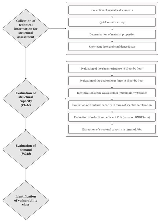
Figure 1.
Scheme of the proposed methodology.
2.1. Collection of Information for Structural Assessment
When dealing with the seismic vulnerability assessment of existing structures, an essential requirement is the achievement of a sufficient knowledge level of the building under investigation, as prescribed by national and international standards [33,34,35]. The knowledge of the building represents, indeed, the base for any type of structural analysis and consequently, the safety assessment and the design of efficient strengthening interventions, if needed. It can be achieved by means of historical analysis, considering a variety of sources including available documentation, relevant data sources (e.g., codes and standards of the time of construction), in situ investigations, and when applicable, in situ testing.
During field investigations, it is recommended to carry out a general survey of the building to verify the correspondence of the current state of the construction with the one deduced from documents previously collected (e.g., drawings, historical documents, and original design, when available), including modifications occurred over time. Besides a geometric and a photographic survey, it is fundamental to identify the structural system and the relevant characteristics for a seismic assessment, namely the type of foundations, the geometry and details of the structural elements (e.g., walls, beams, columns, etc.), slab and roof typologies, non-structural elements, the pre-existing damage state, and the quality of the constituent materials.
In the framework of the simplified method proposed here, a specific procedure has been defined, depending on the structural typology, where the following field investigations should be at least carried out:
- Masonry buildings: (i) the identification of the masonry typologies and corresponding bond pattern and (ii) the evaluation of the quality of the connections between masonry walls and between horizontal and vertical structural elements. These operations can be performed in situ by removing a portion of plaster, if present, on at least two masonry walls to be selected as representative of the construction, according to the knowledge procedure previously carried out.
- Reinforced concrete buildings: (i) the identification of the type of reinforcement (i.e., number, diameter, and position of rebars, as well as concrete cover thickness) in some representative columns of the building, at least one column per floor and (ii) an estimate of the concrete quality. These investigations can be done using pacometer tests, visual inspections, or sclerometer tests on the columns considered to be representative of the resisting elements on each floor. The column strength for horizontal actions is mostly related to its flexural behavior and thus to the amount of steel rebars rather than to the concrete strength.
The mechanical properties of the materials can also be determined considering original design specifications, if available, or default values in accordance with standards at the time of construction or with the literature indications. For masonry structures, it is possible to refer to the strength values reported in the Italian Building Code [34,35] for the specific masonry typologies, as well as to recommendations of regional authorities following specific typological studies [36]. Appropriate safety factors, depending on the investigated materials, and confidence factors, to consider the level of knowledge attained during the investigation, should be used for the definition of design values for the verifications [33,34,35]. In the absence of more detailed indications, to properly account for uncertainties in the evaluation of the material properties, the maximum confidence factor, equal to 1.35 according to Eurocodes and the Italian Building Code, should be used.
2.2. Evaluation of Structural Capacity (PGAc)
Being masonry and RC structures characterized by different collapse mechanisms in the event of an earthquake, two different simplified models will be described in the following sections for the evaluation of their structural capacity.
2.2.1. Masonry Buildings
The evaluation of the collapse PGAc for masonry buildings is carried out floor-by-floor under the assumption of having rigid floors adequately connected with vertical elements and spandrels able to provide a good coupling between the vertical masonry piers, i.e., the condition of strong spandrels–weak piers [37]. Accordingly, the shear capacity of the building can be calculated by considering the in-plane shear capacity of the resisting masonry piers on each floor, taking into account the possible failure modes for a masonry panel subject to a horizontal load, i.e., diagonal cracking, sliding and rocking, and the corresponding failure criterion.
In more detail, the shear resistance for the generic i-th floor of a masonry building is evaluated by identifying two principal directions (x and y) and by quantifying the resisting areas of the masonry piers (Ax,i and Ay,i), as follows:
where Ax,i,n and Ay,i,n are the resisting areas of the n-th masonry pier belonging to the i-th floor in the x and y direction, respectively, while Nwx,i and Nwy,i indicate the number of masonry piers, i.e., resisting elements, on the i-th floor along the x and y direction, respectively. Resisting elements can be identified as the walls continuous from the foundation to the roof with a minimum width of one meter [34,35].
Irrespective of the failure criterion considered, the in-plane shear strength of masonry elements depends on the acting compressive stress σ0,i, which can be calculated, in simplified form, as the weight of the upper floors divided by the total resisting area.
If Wk is evaluated on the i-th floor, the following expression holds:
In the previous equations, qi is the load per unit surface corresponding to the i-th floor, Atot,i is the overall surface of the floor, hi is the height of the i-th floor, pm,i is the weight density of the masonry, ps,i is the load per unit surface given by the dead and live loads in the characteristic combination (i.e., seismic combination), and N is the total number of floors. It should be noted that in the evaluation of the acting compressive stress, the vertical loads are uniformly distributed across all the masonry piers and the stress variation due to seismic action is not taken into account.
The resisting shear Vr,i for the i-th floor can then be computed by considering the weakest direction among x and y, according to the Turnšek and Čačovič (TC) criterion [38] or, alternatively, to the Mann and Müller (MM) failure criterion [39], as follows:
where Amin,i is the minimum area between Ax,i and Ay,i, b is a coefficient depending on the slenderness of the masonry piers, ranging from 1 (squat elements) to 1.5 (slender elements) [35], and σ0,i is the average compressive stress on the masonry elements on the i-th floor—see Equation (2). For the TC criterion (Equation (4)), τ0d represents the design values of the masonry shear strength according to a diagonal cracking failure mode. For the MM criterion (Equation (5)), fv0d is the design shear strength for a sliding failure mode, μ is the local friction coefficient, and φ is a parameter related to the masonry pattern, which can be calculated as ϕ = 2h/l, h and l being the height and the length of the bricks, respectively. The choice between the TC and MM failure criteria can be made by considering the masonry typology under investigation. Typically, the TC criterion can be adopted for irregular masonry typologies (e.g., irregular stone masonry), while the MM failure criterion can be considered for regular masonry typologies (e.g., regular stone or clay brick masonry) for which the diagonal cracking mechanism occurs with a stair-stepped path through the masonry joints [35].
In terms of failure mode, in order to take into account the flexural resistance of the masonry piers, which can limit the overall resistance in the case of slender elements, both slenderness and vertical stresses on the masonry piers should be considered and, as a consequence, the analysis should not be performed floor-by-floor as in the proposed method. Nevertheless, for the simplified and fast methodology proposed here, it might be impractical to collect this information and carry out specific load analyses for every single pier. At the same time, it should also be highlighted that slender piers are characterized by a high flexibility, so they carry a lower amount of shear force compared to squat panels, and observed damage after past seismic events indicate that even with the occurrence of flexural cracks, slender panels maintain their ability to transfer vertical stresses and eventually fail due to diagonal cracking [5,40,41]. For these reasons, the flexural criterion is not further discussed here. However, in case of the availability of the mentioned information and data, the shear resistance corresponding to the flexural failure can be evaluated according to the analytical formulations reported in the standards [34,35] or according to simplified procedures proposed in the literature [42,43].
The evaluation of the acting shear force on the masonry piers to be compared with the capacity is carried out by considering a linear static seismic analysis and a distribution of equivalent static forces (Fi) along the height of the building (one per floor), obtained by imposing a reference acceleration equal to 1g [44].
where zi is the height of the i-th floor above the foundations and Wi is the weight of a single i-th floor, while W is the total weight of the building and g is the acceleration of gravity.
The reference acting shear Vs,i on the i-th floor is then computed as the sum of the shear forces acting on the floors above the i-th one, as
The ratios between the resisting and reference acting shear Vr,i/Vs,i allow evaluating the structural performance for each floor of the masonry piers to identify the weakest floor, which corresponds to the minimum value of that ratio, and consequently, to the definition of the resistance of the building in terms of the spectral acceleration (Sa), which corresponds to the attainment of the failure of the weakest floor. Indeed, since the reference acting shear Vs,i is computed considering a unitary acceleration, the ratio Vr,i/Vs,i corresponds to an acceleration on the structural masses, expressed as a fraction of the gravitational acceleration g [43].
The spectral acceleration Sa, obtained as previously described, is a conventional value of the capacity of the building and should be corrected to account for real structural complexity. With this purpose, several parameters related to structural components and characteristics of the buildings are introduced for the evaluation of a reduction coefficient (Crid), which multiplies the conventional capacity Sa previously obtained, making it more realistic. These parameters, listed in Table 1, were firstly proposed in the II-level seismic vulnerability assessment form of the Italian Group for Protection against Earthquakes (GNDT), denoted as the GNDT form in the following [29]. Among the eleven parameters of the GNDT form, parameter no. 3, related to the estimation of the conventional capacity of the building, is not considered in this procedure because that parameter is quantitatively evaluated as previously described. For each of the ten remaining parameters, a vulnerability class from A (best class) to D (worst class) and a corresponding score are associated with them [45], together with a relative weight of that parameter to take the different relevancies of the various parameters into account—see Appendix A for further information. Scores and weights, whose product can be used in vulnerability index methods [10] to evaluate a global vulnerability index for a building, were determined according to observed damage in post-earthquake surveys [45]. The weights are constant for most parameters, with the exception of parameters no. 5, 7, and 9, whose variable weights should be calculated for the specific building under investigation. In more detail, the weight of parameter no. 5 (w5—horizontal structural element) can be calculated as
where α0 is the percentage of the rigid slabs well connected to the masonry walls. The weight of parameter no. 7 (w7—configuration in elevation) is equal to 0.5 in the presence of plan irregularities determined only by the presence of porticos on the ground floor; otherwise, it is equal to 1. The weight of parameter no. 9 (w9—roof typology) is given by the following equation:
where α1 is equal to 0.25 in the case of reinforced concrete and heavy roofs, i.e., with a self-weight equal to or greater than 2 kN/m2; otherwise, it is equal to zero; and α2 is equal to 0.25 if the ratio between the roof perimeter and the overall support length is greater than or equal to 2.0; otherwise, it will be assumed to be equal to zero.

Table 1.
Parameters, vulnerability classes, scores, and weights of the GNDT form for masonry buildings.
After the identification of the vulnerability class for each parameter, following the indications reported in [45], the reduction coefficient Crid can be computed according to the following expression:
where pk and wk are the score and the weight associated with the k-th parameter, pk,D and wk,D are the score and the weight assuming the worst vulnerability class (D) for all the k-th parameters, and α is a coefficient used for the calibration of the methodology. An interval for the reduction coefficient Crid can be defined as follows: the minimum value (Crid,min) corresponds to the condition in which all the parameters are classified with a vulnerability class D, while the maximum value (Crid,max) is fixed and equal to 1, corresponding to the condition in which vulnerability class A is considered for all the parameters. In this work, the minimum value Crid,min was determined by applying the proposed methodology to four school buildings, on which pushover analyses were also carried out considering an equivalent frame modeling approach [46]. With a parametric analysis carried out on Crid,min, the optimal value was found as the one minimizing differences between the results of the two methodologies in terms of resisting base shear on the investigated buildings, leading to a value of Crid,min equal to 0.6.
The spectral acceleration defining the vulnerability of a building, accounting for its real complexity, is therefore equal to
Finally, to define the seismic intensity corresponding to the life safety limit state, the value of the spectral acceleration Sa,c should be converted into the corresponding peak ground acceleration (PGAc) through the following relationship [44]:
where
- αPM is the modal participation factor, equal to 1 for buildings having one floor above ground only; otherwise, it is equal to 0.8;
- αAD is the spectral amplification factor, considered to be equal to 2.5;
- αDT is a parameter accounting for the dissipative behavior of the structure; for masonry buildings, it is assigned a value of 0.8 or 1 if the dissipative contribution of non-structural elements is relevant or not, respectively;
- αDUC is a ductility factor accounting for the ductile resources of the structure, here assumed to be equal to 2 (see the following considerations).
In order to set the value to be assigned to the ductility factor αDUC, a comparison between the results of the simplified methodology and of a nonlinear static analysis was performed, considering a simple masonry building with a regular configuration both in plan and in elevation (Figure 2a). The characteristics of the building were chosen so as to have a unitary value of the reduction coefficient Crid, i.e., all the parameters of the GNDT form belong to vulnerability class A. To facilitate the comparison, the masonry walls along the x direction were considered as the only resisting elements; therefore, the walls along the y direction were given negligible thickness and stiffness. The mechanical parameters assigned to the masonry are reported in Table 2, with confidence and safety factors set to 1. A rigid reinforced concrete slab was considered, oriented so as to transfer the vertical load to the walls along the x direction only.
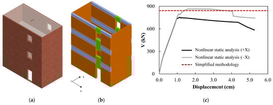
Figure 2.
Comparison between results obtained using the simplified methodology and nonlinear static analysis. (a) Considered masonry building, (b) equivalent frame model, and (c) pushover curves vs. resisting shear Vr.
Table 2.
Mechanical parameters of selected masonry.
For the nonlinear static analysis, the building was modeled according to the equivalent frame method using the software 3Muri v.13 [46] (Figure 2b). With reference to the life safety limit state, two capacity curves were selected for the comparison, obtained with a force distribution proportional to the shape of the first mode of vibration applied along the two +x and −x directions. The capacity curves are reported in Figure 2c and compared with the value of the resisting shear Vr obtained by applying the simplified methodology previously described, showing a good agreement. It should be mentioned that the failure mode of the masonry panels on the ground floor (i.e., the weakest floor) was a diagonal cracking failure mode.
In order to compare the results, the value of the PGAc, that is, the peak ground acceleration causing the structure to reach the life safety limit state, was also determined after the execution of the nonlinear analysis using the N2 method [47]. The values obtained for the two analyses were PGAc = 3.41 m/s2 (+x) and PGAc = 4.03 m/s2 (−x). For the simplified methodology, Equation (12) was used. The equivalence between the average PGAc values computed using the N2 method and the PGAc evaluated with the simplified methodology was obtained for a ductility factor equal to 2.62. Considering the uncertainties about the determination, during the on-site inspections, of the effective ductile capacity of the masonry buildings, which could also be significantly affected by the presence of irregularities, it was decided that for the application of the method on a large scale, a lower value for the ductility factor would be used, i.e., αDUC = 2.
2.2.2. Reinforced Concrete (RC) Buildings
The evaluation of the collapse PGAc for RC buildings follows a procedure similar to that used for masonry buildings. It is carried out floor-by-floor, considering the presence of rigid floors and a shear-type behavior. In general, the shear resistance of the n-th column on the i-th floor (Vcol,n,i) must be calculated by knowing its resisting shear and bending moment. In the framework of the simplified methodology presented here, it is not possible to prescribe the survey of the relevant sections for each column of the building. Therefore, it is recommended to investigate the section of at least one typical column per floor, which should be representative of the columns of the entire floor, e.g., one column belonging to a recurring frame. In more detail, for that column, it is necessary to gather information about (i) the section geometry, (ii) the longitudinal rebars and the shear reinforcements, and (iii) the mechanical properties of the materials in terms of concrete compressive strength and steel tensile strength.
The resisting shear force for a typical column on the i-th floor for the two main directions of the investigated building (x and y) can be determined as
where Vflex,typ,i and Vshear,typ,i are the resisting shear forces associated with a flexural or a shear failure of the column, respectively, both calculated with respect to the x and y direction.
With reference to the flexural failure mode of the column, on the basis of the mechanical properties of the materials and the percentage of steel reinforcement, it is possible to calculate the resisting bending moment (Mcol,typ,i) of the section, obtained from the interaction M–N diagram in correspondence with the value of the axial load at the base of the column (Ncol,typ,i). The latter is calculated through a load analysis, considering the actions given by the dead and live loads in the characteristic combination (i.e., seismic combination). The calculation of the resisting bending moment should be carried out along both the principal directions of the building.
For RC-framed structures entirely cast on-site, assuming a shear-type behavior, the resisting shear forces associated with a flexural failure along the x and y directions, can be calculated as
where and are the resisting bending moments of a typical column in the x and y directions, respectively and hi is the height of the i-th floor. In the case of columns not rigidly connected with the beams on the upper floors but with a hinge connection, as is the case with some typologies of prefabricated structures, the resisting shear forces can be calculated according to a cantilever scheme with Equation (14), removing the “2” coefficient, where resisting bending moments are those of the column base sections. The evaluation of the resisting shear must clearly be made for all the floors of the building.
For RC precast structures, in which beams are simply supported on the column top, it is sufficient to evaluate the resisting shear with reference to the column basis, considering that a cantilever static scheme can be associated to columns.
The resisting shear force for a typical column on the i-th floor, in the x and y directions, is given by
where VRcd and VRsd are the shear resistances corresponding to the compressive concrete failure or to the yielding of the transverse reinforcements, respectively. They can be determined according to the formulations reported in building codes [34,48], referring to a strut-and-tie model with variable inclination of the concrete strut.
By knowing the resisting shear forces for the typical column and in a given cross-section, the resistance of all the columns (with different cross-sections) of a specific floor is determined by using, alternatively, two different simplifying assumptions based on correlation studies performed on a set of buildings (see Section 3) for which information on more than one column was available. In the case of flexural failure, the resisting shear forces can be assumed to be directly proportional to the inertia moment of the columns’ cross-section. This approach seems to be reasonable and reliable, even if it neglects the variability related to the contribution given by the actual amount of reinforcements within the section. From a practical point of view, the resisting shear forces for a generic n-th column on the i-th floor along the x and y directions are given by
where Jx,n,i and Jy,n,i are the inertia moments of the section of the generic n-th column around the x and y axis, respectively; Jx,typ,i and Jy,typ,i are the inertia moments of the section of the typical column around the x- and y-axis, respectively. In the case of shear failure, a direct proportionality is instead assumed between the resisting shear force and the dimension of the cross-section of the column in the considered direction, thus leading to the following expressions:
where dxn,i and dyn,i are the dimensions of the section of the generic n-th column along the x- and y-axis, respectively; and dxtyp,i and dytyp,i are the dimensions of the section of the typical column along the x- and y-axis, respectively.
Finally, the total resisting shear forces of the building for the i-th floor, in the x and y directions, are obtained as the sum of the resistances of all the columns (Ncol) belonging to the specific i-th floor as follows:
Eventually, the resisting shear force for the generic i-th floor is the minimum between the ones along the x and y directions as follows:
The presence of shear walls can be taken into account, considering the prevailing direction of the wall as performed for the walls in masonry buildings. In the case of shear walls in directions different than x and y, the contributions can be computed using simple projections in the two principal directions. Nevertheless, since the structural model is a shear-type model, where the individual elements at a given floor level are considered with no rotations at the end, the lateral stiffness of the walls decreases on the upper floors due to the wall rotations, a circumstance which can be taken into account by defining proper reduction coefficients.
As already performed for the masonry buildings, the intensity of the acting shear force on the columns, to be compared with the capacity, is obtained by considering a linear static seismic analysis and a distribution of equivalent static forces along the height of the building, obtained by imposing an acceleration equal to 1 g. Equations (6) and (7) can be used for the evaluation of the reference acting shear Vs,i on the i-th floor. The ratios between the resisting and reference acting shear Vr,i/Vs,i allow evaluating the structural performance for each floor, identifying the weakest one corresponding to the minimum value of that ratio, and consequently, to the definition of the resistance of the building in terms of spectral acceleration (Sa). Indeed, since the reference acting shear is computed considering a unitary acceleration, the ratio Vr,i/Vs,i corresponds to an acceleration on the structural masses, expressed as a fraction of the gravitational acceleration g [43]. As already discussed for masonry buildings, the obtained Sa value is conventional information about the capacity of the building and should be corrected to account for real structural complexity.
A procedure similar to the one presented for masonry buildings is proposed here for the evaluation of the reduction coefficient Crid. Ten parameters are considered for RC buildings, based on the GNDT form [29], with specific definitions in terms of vulnerability classes, scores, and weights, as reported in Table 3. After the identification of the vulnerability class, following the indications reported in [49] (see Appendix B for further information), a unique score pk and a unitary weight are associated with each parameter. The reduction coefficient Crid can then be computed according to Equation (10). In this case, the calibration procedure allowed obtaining a minimum value of Crid,min equal to 0.5, corresponding to the condition in which the worst vulnerability class is considered for all the parameters. The maximum value of the reduction coefficient Crid,max is fixed and equal to 1, corresponding to the condition in which all the parameters are classified as vulnerability class A.
Table 3.
Parameters, vulnerability classes, scores, and weights of the GNDT form for RC buildings.
The collapse pseudo-acceleration, accounting for the real complexity of the building, is computed using Equation (11). Finally, to define the seismic intensity which the building is able to withstand without collapse, the value of the spectral acceleration should be converted into the corresponding peak ground acceleration (PGAc) according to Equation (12). The only differences with respect to the case of masonry buildings are the definitions of the following parameters:
- αDT is assumed to be equal to 1 if the resistant contribution of the non-structural elements is significant compared to that of the main resisting system and considered in the analysis; otherwise, it is assumed to be equal to 0.8;
- αDUC is a ductility factor which can assume values between 2 and 3; in more detail, a lower value is associated with fragile mechanisms (shear failure), while a higher value is used for ductile mechanisms (flexural failure).
2.3. Safety Evaluation and Classification
After evaluating the structural capacity, the seismic vulnerability of existing masonry and RC buildings is assessed through a comparison, referring to the life safety limit state, between capacity and demand, expressed in terms of PGA, the latter being evaluated with reference to the elastic response spectrum. In order to take the described simplifications into account and to produce a more easily readable result about the seismic safety of the construction, a simple classification is proposed, inspired by other classifications proposed in the literature [9], according to which buildings can be categorized in five homogeneous vulnerability classes depending on the ratio between the capacity (PGAc) and the demand (PGAd). The intervals for the definition of these classes are reported in Table 4.
Table 4.
Identification of vulnerability classes on the basis of the capacity-to-demand ratio.
At this stage, any potential local vulnerability or critical issue detected from the inspections that was not adequately considered in the calculations but which may represent a weak spot in the structural behavior in the event of an earthquake, come into play. Indeed, if a significant number of critical elements is identified in a building, this must be given a higher class with respect to the one resulting from the ratio between PGA values alone. This allows, although in a simplified way, taking relevant local phenomena into account, such as an out-of-plane collapse of masonry walls, insufficient shear reinforcement in RC columns, serious geometric or structural irregularities, etc.
Based on the proposed procedure and classification, it is possible to quickly assess a large number of buildings and define priorities for successive, more complex analyses and interventions. As an example, buildings belonging to Class V should be given top priority, and they will be the first ones to undergo more accurate seismic vulnerability assessment procedures as reported in building codes [33,34,35]. On the basis of the obtained results, local or global interventions may then be designed. The same procedure should then be applied for all the vulnerability classes, in descending order.
3. Application and Validation of the Methodology
The possibility of applying a simplified assessment method is crucial in situations where a quick evaluation is needed to plan further actions. This is especially valid for public and high-priority buildings, such as schools, for which an allocation of resources for interventions or further analyses should be properly planned. Moreover, at the municipal or regional level, these building typologies might be among the first ones in which first-level assessments can be performed.
The methodology proposed in this research was applied to 140 masonry and RC school buildings located in the province of Ravenna, Italy. They were characterized by different numbers of floors and ages of construction—see Table 5 and Table 6.
Table 5.
Distribution of masonry and RC buildings according to the number of floors above ground.
Table 6.
Distribution of masonry and RC buildings according to the age of construction.
The obtained ratios between the capacity and demand, in terms of PGA, are reported in ascending order in Figure 3 and Figure 4 for masonry and RC buildings, respectively. Vulnerability classes associated with the various buildings are indicated with different colors in the histograms. After the evaluation of local vulnerabilities, for some of the buildings, a higher vulnerability class was selected (e.g., see some red bars among orange ones in the graphs), leading to the safety classification reported in Figure 5 for the various typologies and for the entire building dataset. It can be observed that none of the masonry buildings exhibited a structural capacity greater than the demand currently requested by the Italian Building Code and that, in general, masonry buildings are more vulnerable that RC buildings.
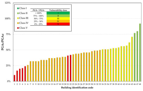
Figure 3.
Capacity-to-demand ratios (PGAc/PGAd, in percentage) and identification of the vulnerability class for masonry buildings.
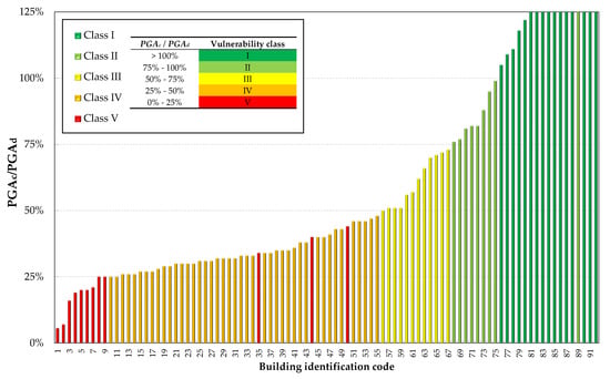
Figure 4.
Capacity-to-demand ratios (PGAc/PGAd, in percentage) and identification of the vulnerability class for RC buildings.
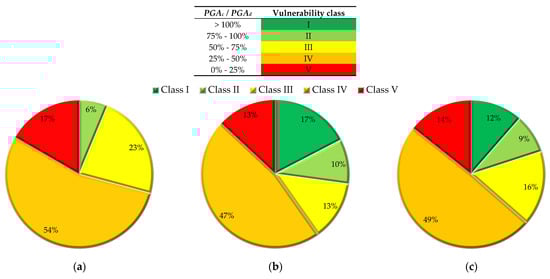
Figure 5.
Percentage of buildings belonging to each vulnerability class. (a) Masonry buildings; (b) RC buildings; and (c) entire dataset.
It should be highlighted that besides the importance of assessing single building typologies, there is a need to aggregate the obtained results for the entire building stock to easily identify priorities for further in-depth analyses.
To validate the methodology and to determine if it is reliable to define the vulnerability of buildings not only in terms of relative results at the territorial scale but also in absolute terms, vulnerability assessments were performed according to prescriptions from codes [33,34,35] on 14 masonry and 4 RC buildings selected as representatives from the building stock. In more detail, after the attainment of a specific knowledge level (usually LC1), nonlinear static analyses were performed, considering both main building directions. For masonry buildings, numerical simulations were performed by modeling the structures according to an equivalent frame method; for RC buildings, the effect of infills was not considered. For all buildings, only global analyses were performed because the simplified methodology does not explicitly consider local mechanisms. A safety assessment was then performed in terms of the PGAc/PGAd ratio. The results obtained for the weakest direction were compared to the ones obtained with the simplified methodology proposed here for masonry and RC buildings—see Figure 6a,b. In general, the simplified methodology provided vulnerability estimates in line with the results obtained from the finite element (FE) analyses, with an average error, in terms of differences in the PGAc values, lower than 20%. It can be noticed that for masonry buildings, the PGAc/PGAd ratio was sometimes higher than the one obtained from the FE analyses. This can be explained by considering several aspects: firstly, the simplified methodology implies the attainment of failure for all the vertical structural elements, while not all the elements reached failure in the nonlinear static analyses; and secondly, the vertical stress variation due to the seismic action, which might affect the activation of a different failure mechanism, is not considered in the simplified methodology. However, the correlation between the results of the FE analyses and those obtained with the simplified methodology (Figure 7), considering the whole dataset of results for masonry and RC buildings, shows a very good agreement, i.e., the interpolation line (black line) is almost coincident with the bisector (red dashed line).
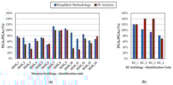
Figure 6.
Comparison between FE analysis and simplified methodology. (a) Masonry buildings and (b) RC buildings.
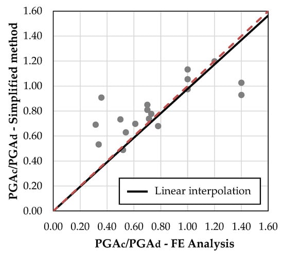
Figure 7.
Correlation between the results of the FE analyses and the simplified methodology.
To provide further validation, vulnerability classes were also assigned based on the results obtained from the numerical analyses and compared with the ones obtained from the simplified procedure (Figure 8). It should be noted that the same vulnerability class was obtained in 61% of the cases, while a higher vulnerability class was obtained from the simplified methodology in 17% of the cases; for the remaining 22% of the buildings, the vulnerability class was lower. These results confirm that the simplified methodology can be considered reliable in its application on large building stocks.
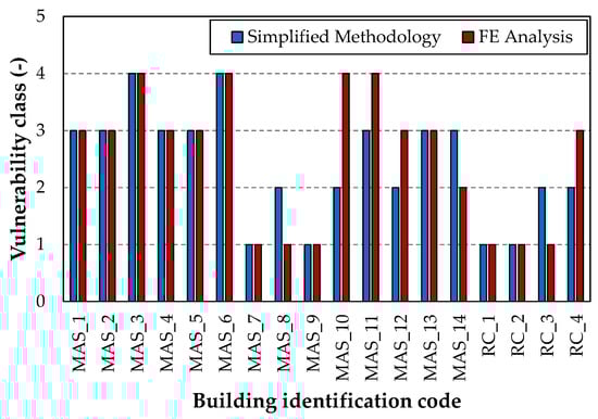
Figure 8.
Comparison between FE analysis and simplified methodology in terms of vulnerability class.
4. Conclusions
In this paper, a methodology is proposed for the comparative assessment of the seismic vulnerability of existing building stocks. The methodology makes use of both quantitative and qualitative inputs and is intended to assess the global behavior of masonry and RC buildings subject to seismic actions by accounting for the structural complexity in a simplified and expeditious way.
- The proposed method can be considered as a simplified analytical method—analytical because the basic shear resistance of the building is calculated analytically starting with a few geometrical and mechanical characteristics of the construction and simplified because as few parameters as possible, easily available after a short survey, are used. PGA is used as an intensity measure, and spectral acceleration is directly obtained from the PGA through a spectral amplification factor set equal to 2.5. The method differs from other mechanical models for masonry buildings (see, e.g., [50]) and RC buildings (see, e.g., [28]), which are based on simplified nonlinear analyses of the most representative parts of the structure. The most relevant advantage is that the proposed approach requires a smaller number of mechanical parameters and a priori assumptions on the mechanical behavior of the structure; this is very important because very limited surveys are possible. One disadvantage is that only the life safety limit state is considered because other damage states require displacements to be estimated and thus, nonlinear analyses.
The proposed methodology was calibrated and subsequently validated through comparisons with results obtained from refined FE analyses, showing a good agreement. It was also applied to 140 school buildings to demonstrate its suitability for large-scale studies, oriented to define priorities for interventions in the framework of decision making at the territorial level for seismic risk reduction. Seeing as the results presented are promising, further studies are needed to confirm that the methodology can also be used for the assessment of single buildings or for the derivation of typological fragility curves for seismic risk assessment at the territorial scale. Indeed, some developments of the methodology are currently under way, such as the calibration of the reduction coefficients for more specific structural typologies or the inclusion of aspects, currently not specifically considered (e.g., strong building irregularities) but capable of significantly influencing the seismic behavior of a building.
Author Contributions
Conceptualization, C.M. and M.S.; data curation, C.M.; funding acquisition, M.S.; methodology, C.M. and M.S.; software, F.F.; validation, F.F.; writing—original draft, F.F.; writing—review and editing, F.F., C.M. and M.S. All authors have read and agreed to the published version of the manuscript.
Funding
This study received funding from the European Union NextGenerationEU and was carried out in the framework of the project PNRR RETURN (National Recovery and Resilience Plan—NRRP, Mission 4, Component 2, Investment 1.3—D.D. 1243 2/8/2022, PE0000005). The views and opinions expressed are solely those of the authors and do not necessarily reflect those of the European Union, nor can the European Union be held responsible for them. The research was also financially supported by the Italian Department of Civil Protection (ReLUIS 2024-2026 Grant—WP4).
Data Availability Statement
The data presented in this study are available in the article. Further inquiries are available on request from the corresponding author.
Acknowledgments
The authors would like to thank the engineer Gianluca Perri for the fruitful discussions about the application of the methodology.
Conflicts of Interest
The authors declare that this study received funding from the European Union NextGenerationEU. The funder was not involved in the study design, collection, analysis, interpretation of data, the writing of this article, or the decision to submit it for publication.
Appendix A. GNDT form Parameters for Masonry Buildings
With reference to masonry buildings, indications are provided here about the main criteria to be followed for the choice of the class (A, B, C, or D) for the ten parameters reported in the II-level seismic vulnerability assessment form of the Italian Group for Protection against Earthquakes (GNDT form). Further details can be found in [45].
- N° 1—Typology and organization of the resisting system
The parameter is aimed at evaluating the box-like behavior of a masonry building. The organization of the vertical structural elements is considered, regardless of the materials and specific characteristics of the single masonry panels; the most important factor to be evaluated is the presence and the efficiency of the connections between orthogonal walls along the height of the building.
To assess the degree of connection between orthogonal walls, it is necessary to investigate the quality and workmanship of the stones/bricks at the corners with inspections, verifying if the connection involves the entire thickness of the wall or just part of it. Additionally, the presence and efficiency of steel ties or reinforced concrete ring beams at the floor level should be investigated.
- N° 2—Quality of the resisting system
The quality of the resisting system is assessed based on the following:
- The type and homogeneity of the materials, i.e., the type and quality of the blocks, the type and state of conservation of the mortar;
- The bond pattern, with reference to the dimensions of the blocks and their regular or irregular disposition;
- The presence of a transversal connection between wall leaves.
Classes from A to D are defined in the GNDT manual [45] based on specific combinations of the characteristics listed above. Pictures are also provided to facilitate the classification.
- N° 3—Conventional resistance
The parameter, as defined in the GNDT manual [45], is not considered in this work.
- N° 4—Building location and foundations
The aim of this parameter is to evaluate, as much as possible through visual inspections, the influence of the soil and of the foundations on the seismic response of a structure. In particular, the following aspects should be considered:
- The consistency and slope of the soil;
- The presence of foundations;
- The presence of foundations at different heights;
- The unbalanced pressures of the embankments.
Classes from A to D are defined with an abacus in the GNDT manual [45] based on specific combinations of the characteristics listed above.
- N° 5—Horizontal structural elements
This parameter expresses the role of the horizontal elements in ensuring a good box-like behavior of a building. For the choice of class, good connections with the vertical walls and the in-plane stiffness are considered. In the GNDT manual [45], schemes and pictures are provided to facilitate the distinction between rigid and deformable floor typologies and between effective and not effective connections with the vertical structural elements.
- N° 6—Plan configuration
To assess the regularity of the plan configuration, the ratio between the two dimensions in plan is evaluated for rectangular plan buildings. For buildings not characterized by a rectangular plan, it is necessary to determine the entity of the deviation from the rectangular shape. Based on the quantitative evaluation of these parameters, classes are defined considering the most unfavorable one.
- N° 7—Configuration in elevation
For masonry buildings, especially the oldest ones, the irregularities in elevations are mainly due to the presence of towers or porticos. The relevance of porticos is considered by evaluating the ratio between the plan surface covered by the porticos over the total plan surface. In the presence of towers having significant height and mass, the ratio between the height of the tower and the total height of the building should be evaluated and, more generally, variations in terms of mass along the height of the building should be assessed as well. Also in this case, schemes are provided in the GNDT manual [45] to facilitate classification, according to the mentioned aspects.
- N° 8—Maximum distance between masonry walls
This parameter takes into account the presence of walls effectively connected with transversal (orthogonal) walls, which may prevent the activation and development of out-of-plane failure mechanisms. If a good connection between these walls exists, the classes are defined in function of the ratio between the distance within the transversal walls and the thickness of the wall connected to them.
- N° 9—Roof typology
The roof typology can influence the seismic behavior of masonry buildings, mainly depending on the following:
- The thrusting action of the roof on the perimetral walls;
- The connection of the roof structural elements to the masonry walls (e.g., the presence of ring beams or steel ties, etc.);
- The roof weight;
- The difference in terms of stiffness and resistance with respect to the masonry;
- The support length of the roof.
The evaluation of all these elements by visual inspections will lead to the definition of a specific class according to the GNDT manual [45].
- N° 10—Non-structural elements
The presence of elements that can cause damage to people or things, such as cornices and window frames, should be identified even if they are secondary elements in the vulnerability assessment of the building.
- N° 11—State of damage
The class is defined according to the state of conservation of the building, considering the diffusion of damage throughout the structures and the width of cracks.
Appendix B. GNDT form Parameters for RC Buildings
With reference to reinforced concrete (RC) buildings, indications are provided here about the main criteria to be followed for the choice of the class (A, B, C, or D) for the ten parameters reported in the II-level seismic vulnerability assessment form of the Italian Group for Protection against Earthquakes (GNDT form). Further details can be found in [49].
- N° 1—Typology and organization of the resisting system
For the evaluation of this parameter, the main resisting system to lateral loads should be identified as the one capable of carrying at least 70% of the design’s horizontal actions. With reference to an RC frame building, the structural behavior can be classified considering the stiffness (e.g., accounting for the presence of RC walls or good-quality masonry infills) and the expected failure mode in the event of an earthquake (i.e., brittle or ductile).
- N° 2—Quality of the resisting system
The quality of the resisting system is assessed based on the following:
- The type and quality of the materials;
- The adopted design criteria;
- The adopted construction practices.
Information about the age of construction and about codes or standards in force at the time will help, together with information about the construction practices in the specific territory in which the building is located. The state of conservation of the building and the quality of the materials should also be assessed through visual inspections, at least.
- N° 3—Conventional resistance
The parameter, as defined in the GNDT manual [49], is not considered in this work.
- N° 4—Building location and foundations
The aim of this parameter is to evaluate, as much as possible through visual inspections, the influence of the soil and of the foundations on the seismic response of a structure. In particular, the following aspects should be considered:
- The consistency and slope of the soil;
- The presence of foundations;
- The foundation typology.
- N° 5—Horizontal structural elements
This parameter takes into account the in-plane stiffness of the slabs and their effective connection to the RC vertical structural elements. For the choice of the class, depending on the slab typology, it is essential to evaluate either the presence of a reinforced concrete slab, the presence of structural elements resistant to tension and compression (slab joists) with a horizontal bracing system, or the presence of efficient connections between precast elements.
- N° 6—Plan configuration
To assess the regularity of the plan configuration, the plan shape, together with the mass and the lateral stiffness distributions, should be considered. In more detail, the ratio between the two dimensions in plan should be evaluated for rectangular plan buildings, while for buildings not characterized by a rectangular plan, plan setbacks should be quantified, also evaluating if structural elements are distributed along the perimeter or if they are displaced inward. Moreover, the eccentricity between the center of mass and the center of stiffness should be calculated.
- N° 7—Configuration in elevation
The regularity in elevation is assessed with reference both to the continuity of the resisting system along the height of the building and to possible variations in lateral stiffness and mass from the base to the top of the building. Schemes are provided in the GNDT manual [46] to facilitate classification.
- N° 8—Connections and critical elements
The parameter considers the quality of the connections between the structural elements, such as beam–column joints, connections between slabs and beams, between columns and foundations, etc. Critical elements are the ones intended to be of primary importance for the resistance against horizontal actions, e.g., connections, squat elements, etc. Specific criteria, both qualitative and quantitative, are defined in the GNDT manual [46] for classification.
- N° 9—Low-ductility elements
The parameter accounts for the cases in which the behavior of the building or part of it is critical due to the presence of fragile elements or very rigid, low-ductile elements. The presence of short columns is taken into account by means of this parameter. For classification, the free height of the resisting elements is the main parameter to be evaluated.
- N° 10—Non-structural elements
Non-structural elements may be subdivided into two groups: elements which may fall outside the building (e.g., infills, parapets, cornices, chimneys) and elements which may fall inside the building (internal walls, furniture, etc.). The stability of these elements in the event of an earthquake, considering the potential presence of connections, should be evaluated.
- N° 11—State of damage
The class is defined according to the state of conservation of the building, considering the integrity of vertical structural elements, foundations, and non-structural elements (in order of importance). For these elements, the presence of cracks, their entity, and the presence of damage associable to specific failure modes should be assessed.
References and Notes
- Tesfamariam, S.; Liu, Z. Earthquake Induced Damage Classification for Reinforced Concrete Buildings. Struct. Saf. 2010, 32, 154–164. [Google Scholar] [CrossRef]
- Peek, L.; Ryder, S.S.; Moresco, J.; Tucker, B. Disaster Risk Reduction Strategies in Earthquake-Prone Cities. In Multi-Hazard Approaches to Civil Infrastructure Engineering; Springer International Publishing: Cham, Switzerland, 2016; pp. 507–532. [Google Scholar]
- Freddi, F.; Galasso, C.; Cremen, G.; Dall’Asta, A.; Di Sarno, L.; Giaralis, A.; Gutiérrez-Urzúa, F.; Málaga-Chuquitaype, C.; Mitoulis, S.A.; Petrone, C.; et al. Innovations in Earthquake Risk Reduction for Resilience: Recent Advances and Challenges. Int. J. Disaster Risk Reduct. 2021, 60, 102267. [Google Scholar] [CrossRef]
- D’Ayala, D.F.; Paganoni, S. Assessment and Analysis of Damage in L’Aquila Historic City Centre after 6th April 2009. Bull. Earthq. Eng. 2011, 9, 81–104. [Google Scholar] [CrossRef]
- Penna, A.; Morandi, P.; Rota, M.; Manzini, C.F.; da Porto, F.; Magenes, G. Performance of Masonry Buildings during the Emilia 2012 Earthquake. Bull. Earthq. Eng. 2014, 12, 2255–2273. [Google Scholar] [CrossRef]
- Ozturk, M.; Arslan, M.H.; Korkmaz, H.H. Effect on RC Buildings of 6 February 2023 Turkey Earthquake Doublets and New Doctrines for Seismic Design. Eng. Fail. Anal. 2023, 153, 107521. [Google Scholar] [CrossRef]
- Di Ludovico, M.; Digrisolo, A.; Graziotti, F.; Moroni, C.; Belleri, A.; Caprili, S.; Carocci, C.; Dall, A.; De Martino, G.; De Santis, S.; et al. The Contribution of ReLUIS to the Usability Assessment of School Buildings Following the 2016 Central Italy Earthquake. Boll. Di Geofis. Teor. E Appl. 2017, 58, 353–376. [Google Scholar] [CrossRef]
- Di Ludovico, M.; Del Gaudio, C.; Del Zoppo, M.; Gaetani d, M.; Baltzopoulos, G.; Apuzzo, R.; Giulivo, M.; Manfredi, V.; Sisti, R.; Grella, A.; et al. Italian Joint Reconnaissance Mission—Türkiye; Italian Department of Civil Protection: Rome, Italy, 2023. [Google Scholar]
- Cosenza, E.; Del Vecchio, C.; Di Ludovico, M.; Dolce, M.; Moroni, C.; Prota, A.; Renzi, E. The Italian Guidelines for Seismic Risk Classification of Constructions: Technical Principles and Validation. Bull. Earthq. Eng. 2018, 16, 5905–5935. [Google Scholar] [CrossRef]
- Calvi, G.M.; Pinho, R.; Magenes, G.; Bommer, J.J.; Restrepo-Velez, L.F.; Crowley, H. Development of Seismic Vulnerability Assessment Methodologies Over the Past 30 Years. ISET J. Earthq. Technol. 2006, 43, 75–104. [Google Scholar]
- Rota, M.; Penna, A.; Strobbia, C.L. Processing Italian Damage Data to Derive Typological Fragility Curves. Soil Dyn. Earthq. Eng. 2008, 28, 933–947. [Google Scholar] [CrossRef]
- Ioannou, I.; Bertelli, S.; Verrucci, E.; Arcidiacono, V.; Rossetto, T. Empirical Fragility Assessment of Residential Buildings Using Data from the Emilia 2012 Sequence of Earthquakes. Bull. Earthq. Eng. 2021, 19, 1765–1795. [Google Scholar] [CrossRef]
- De Martino, G.; Di Ludovico, M.; Prota, A.; Moroni, C.; Manfredi, G.; Dolce, M. Estimation of Repair Costs for RC and Masonry Residential Buildings Based on Damage Data Collected by Post-Earthquake Visual Inspection. Bull. Earthq. Eng. 2017, 15, 1681–1706. [Google Scholar] [CrossRef]
- Autiero, F.; De Martino, G.; Di Ludovico, M.; Prota, A. Structural Assessment of Ancient Masonry Structures: An Experimental Investigation on Rubble Stone Masonry. Int. J. Archit. Herit. 2023, 17, 815–828. [Google Scholar] [CrossRef]
- Rota, M.; Penna, A.; Magenes, G. A Framework for the Seismic Assessment of Existing Masonry Buildings Accounting for Different Sources of Uncertainty. Earthq. Eng. Struct. Dyn. 2014, 43, 1045–1066. [Google Scholar] [CrossRef]
- Simões, A.; Milošević, J.; Meireles, H.; Bento, R.; Cattari, S.; Lagomarsino, S. Fragility Curves for Old Masonry Building Types in Lisbon. Bull. Earthq. Eng. 2015, 13, 3083–3105. [Google Scholar] [CrossRef]
- Milosevic, J.; Cattari, S.; Bento, R. Definition of Fragility Curves through Nonlinear Static Analyses: Procedure and Application to a Mixed Masonry-RC Building Stock. Bull. Earthq. Eng. 2020, 18, 513–545. [Google Scholar] [CrossRef]
- Battaglia, L.; Ferreira, T.M.; Lourenço, P.B. Seismic Fragility Assessment of Masonry Building Aggregates: A Case Study in the Old City Centre of Seixal, Portugal. Earthq. Eng. Struct. Dyn. 2021, 50, 1358–1377. [Google Scholar] [CrossRef]
- Ferretti, F.; Simoni, E.; Buratti, N.; Mazzotti, C. Typological Fragility Analysis of Masonry Buildings in Emilia Romagna Region (Italy). Bull. Earthq. Eng. 2023, 21, 3321–3356. [Google Scholar] [CrossRef]
- Salamida, G.; Buratti, N. Fragility Models for RC Frames with Masonry Infills and Analysis of the Efficiency of Different IMs. Procedia Struct. Integr. 2023, 44, 139–146. [Google Scholar] [CrossRef]
- Shabani, A.; Kioumarsi, M.; Zucconi, M. State of the Art of Simplified Analytical Methods for Seismic Vulnerability Assessment of Unreinforced Masonry Buildings. Eng. Struct. 2021, 239, 112280. [Google Scholar] [CrossRef]
- Silva, V.; Akkar, S.; Baker, J.; Bazzurro, P.; Castro, J.M.; Crowley, H.; Dolsek, M.; Galasso, C.; Lagomarsino, S.; Monteiro, R.; et al. Current Challenges and Future Trends in Analytical Fragility and Vulnerability Modeling. Earthq. Spectra 2019, 35, 1927–1952. [Google Scholar] [CrossRef]
- Ferreira, T.M.; Mendes, N.; Silva, R. Multiscale Seismic Vulnerability Assessment and Retrofit of Existing Masonry Buildings. Buildings 2019, 9, 91. [Google Scholar] [CrossRef]
- Mazumder, R.K.; Rana, S.; Salman, A.M. First Level Seismic Risk Assessment of Old Unreinforced Masonry (URM) Using Fuzzy Synthetic Evaluation. J. Build. Eng. 2021, 44, 103162. [Google Scholar] [CrossRef]
- Achs, G.; Adam, C. Rapid Seismic Evaluation of Historic Brick-Masonry Buildings in Vienna (Austria) Based on Visual Screening. Bull. Earthq. Eng. 2012, 10, 1833–1856. [Google Scholar] [CrossRef]
- FEMA P-155; Rapid Visual Screening of Buildings for Potential Seismic Hazards: Supporting Documentation—Third Edition. Applied Technology Council for the Federal Emergency Management Agency: Washington, DC, USA, 2015.
- Aggarwal, Y.; Saha, S.K. An Improved Rapid Visual Screening Method for Seismic Vulnerability Assessment of Reinforced Concrete Buildings in Indian Himalayan Region. Bull. Earthq. Eng. 2023, 21, 319–347. [Google Scholar] [CrossRef]
- Del Vecchio, C.; Gentile, R.; Di Ludovico, M.; Uva, G.; Pampanin, S. Implementation and Validation of the Simple Lateral Mechanism Analysis (SLaMA) for the Seismic Performance Assessment of a Damaged Case Study Building. J. Earthq. Eng. 2020, 24, 1771–1802. [Google Scholar] [CrossRef]
- Gruppo Nazionale per la Difesa dai Terremoti. Censimento di Vulnerabilità Degli Edifici Pubblici, Strategici e Speciali Nelle Regioni Abruzzo, Basilicata, Calabria, Campania, Molise, Puglia e Sicilia-Schede Di 1° e 2° Livello Di Vulnerabilità e Di Rilevamento Del Danno Per Edifici in c.a. e Muratura; Dipartimento della Protezione Civile: Roma, Italy, 1999. (In Italian) [Google Scholar]
- Luco, N.; Cornell, C.A. Structure-Specific Scalar Intensity Measures for Near-Source and Ordinary Earthquake Ground Motions. Earthq. Spectra 2007, 23, 357–392. [Google Scholar] [CrossRef]
- Eads, L.; Miranda, E.; Lignos, D.G. Average Spectral Acceleration as an Intensity Measure for Collapse Risk Assessment. Earthq. Eng. Struct. Dyn. 2015, 44, 2057–2073. [Google Scholar] [CrossRef]
- Yakut, A.; Sucuoğlu, H.; Akkar, S. Seismic Risk Prioritization of Residential Buildings in Istanbul. Earthq. Eng. Struct. Dyn. 2012, 41, 1533–1547. [Google Scholar] [CrossRef]
- CEN EN 1998-1; Eurocode 8: Design of Structures for Earthquake Resistance—Part 1: General Rules, Seismic Actions and Rules for Buildings. European Committee for Standardization: Brussels, Belgium, 1998.
- Ministero delle Infrastrutture e dei Trasporti Aggiornamento Delle «Norme Tecniche per Le Costruzioni» (in Italian). Gazz. Uff. della Repubb. Ital. 2018, 42, 1–372.
- Ministero delle Infrastrutture e dei Trasporti Circolare 21 Gennaio 2019—Istruzioni per l’applicazione Dell’«Aggiornamento Delle “Norme Tecniche per Le Costruzioni”». Gazz. Uff. della Repubb. Ital. 2019, 1–337. Available online: https://sttan.it/norme/NTC2018/NTC2018_Circ_21_01_2019_n7-CS_LL_PP.pdf (accessed on 10 June 2024). (In Italian).
- Ferretti, F.; Ferracuti, B.; Mazzotti, C.; Savoia, M. Destructive and Minor Destructive Tests on Masonry Buildings: Experimental Results and Comparison between Shear Failure Criteria. Constr. Build. Mater. 2019, 199, 12–29. [Google Scholar] [CrossRef]
- FEMA 365; Prestandard and Commentary for the Seismic Rehabilitation of Buildings. Federal Emergency Management Agency: Washington, DC, USA, 2000.
- Turnsek, V.; Cacovic, F. Some Experimental Results on the Strength of Brick Masonry Walls. In Proceedings of the 2nd International Brick Masonry Conference, Stoke-on-Trent, UK, 12–15 April 1971. [Google Scholar]
- Mann, W.; Muller, H. Failure of Shear-Stressed Masonry—An Enlarged Theory, Tests and Application to Shear Walls. Proc. Br. Ceram. Soc. 1982, 30, 223–235. [Google Scholar]
- Parisi, F.; Augenti, N. Earthquake Damages to Cultural Heritage Constructions and Simplified Assessment of Artworks. Eng. Fail. Anal. 2013, 34, 735–760. [Google Scholar] [CrossRef]
- Indirli, M.; Kouris, S.L.A.; Formisano, A.; Borg, R.P.; Mazzolani, F.M. Seismic Damage Assessment of Unreinforced Masonry Structures After The Abruzzo 2009 Earthquake: The Case Study of the Historical Centers of L’Aquila and Castelvecchio Subequo. Int. J. Archit. Herit. 2013, 7, 536–578. [Google Scholar] [CrossRef]
- Dolce, M. Schematizzazione e Modellazione Degli Edifici in Muratura Soggetti Ad Azioni Sismiche. L’industria Delle Costr. 1991, 25, 44–57. [Google Scholar]
- Dolce, M.; Moroni, C. La Valutazione Della Vulnerabilità e Del Rischio Sismico Degli Edifici Pubblici Mediante Le Procedure VC e VM; Dipartimento della Protezione Civile: Rome, Italy, 2005. [Google Scholar]
- Dolce, M.; Masi, A.; Moroni, C.; Liberatore, D.; Laterza, M.; Ponzo, F.; Cacosso, A.; D’alessandro, G.; Faggella, M.; Gigliotti, R.; et al. Valutazione Della Vulnerabilità Sismica Di Edifici Scolastici Della Provincia Di Potenza. In Proceedings of the XI Congresso Nazionale “L’ingegneria Sismica in Italia”, Genova, Italy, 25–29 January 2004. [Google Scholar]
- Regione Toscana, Manuale per La Compilazione Della Scheda GNDT/CNR Di II Livello—Versione Modificata Della Regione Toscana, Direzione Generale Delle Politiche Territoriali Ad Ambientali, Settore: Servizio Sismico Regionale 2003. (In Italian)
- Lagomarsino, S.; Penna, A.; Galasco, A.; Cattari, S. TREMURI Program: An Equivalent Frame Model for the Nonlinear Seismic Analysis of Masonry Buildings. Eng. Struct. 2013, 56, 1787–1799. [Google Scholar] [CrossRef]
- Fajfar, P. A Nonlinear Analysis Method for Performance-Based Seismic Design. Earthq. Spectra 2000, 16, 573–592. [Google Scholar] [CrossRef]
- EN1992-1-1:2004+A1:2014; Eurocode 2: Design of Concrete Structures—Part 1-1: General Rules and Rules for Buildings. European Committee for Standardization: Brussels, Belgium, 2014.
- Regione Marche Manuale per La Compilazione Della Scheda GNDT/CNR Di II Livello per Edifici in Calcestruzzo Armato 2004. (In Italian)
- Lagomarsino, S.; Cattari, S. Fragility Functions of Masonry Buildings; Pitilakis, K., Crowley, H., Kaynia, A., Eds.; Springer: Berlin/Heidelberg, Germany, 2014; pp. 111–156. [Google Scholar]
Disclaimer/Publisher’s Note: The statements, opinions and data contained in all publications are solely those of the individual author(s) and contributor(s) and not of MDPI and/or the editor(s). MDPI and/or the editor(s) disclaim responsibility for any injury to people or property resulting from any ideas, methods, instructions or products referred to in the content. |
© 2024 by the authors. Licensee MDPI, Basel, Switzerland. This article is an open access article distributed under the terms and conditions of the Creative Commons Attribution (CC BY) license (https://creativecommons.org/licenses/by/4.0/).